CN110880947B - Coupling device, surface wave coupling method, and open-line surface wave wireless coverage system - Google Patents
Coupling device, surface wave coupling method, and open-line surface wave wireless coverage systemDownload PDFInfo
- Publication number
- CN110880947B CN110880947BCN201811033366.3ACN201811033366ACN110880947BCN 110880947 BCN110880947 BCN 110880947BCN 201811033366 ACN201811033366 ACN 201811033366ACN 110880947 BCN110880947 BCN 110880947B
- Authority
- CN
- China
- Prior art keywords
- mode
- wave
- waveguide
- guided wave
- electromagnetic wave
- Prior art date
- Legal status (The legal status is an assumption and is not a legal conclusion. Google has not performed a legal analysis and makes no representation as to the accuracy of the status listed.)
- Active
Links
- 238000010168coupling processMethods0.000titleclaimsabstractdescription209
- 238000005859coupling reactionMethods0.000titleclaimsabstractdescription188
- 230000008878couplingEffects0.000titleclaimsabstractdescription187
- 230000001902propagating effectEffects0.000claimsabstractdescription59
- 238000001914filtrationMethods0.000claimsabstractdescription36
- 238000006243chemical reactionMethods0.000claimsabstractdescription23
- 229910052751metalInorganic materials0.000claimsdescription108
- 239000002184metalSubstances0.000claimsdescription108
- 238000004891communicationMethods0.000claimsdescription11
- 238000002834transmittanceMethods0.000claimsdescription3
- 230000005540biological transmissionEffects0.000abstractdescription35
- -1polyethylenePolymers0.000description52
- 239000004698PolyethyleneSubstances0.000description51
- 229920000573polyethylenePolymers0.000description51
- 238000000034methodMethods0.000description29
- 239000000463materialSubstances0.000description27
- 230000008569processEffects0.000description19
- 238000010586diagramMethods0.000description16
- 238000009826distributionMethods0.000description14
- 230000001808coupling effectEffects0.000description10
- RYGMFSIKBFXOCR-UHFFFAOYSA-NCopperChemical compound[Cu]RYGMFSIKBFXOCR-UHFFFAOYSA-N0.000description9
- 238000005516engineering processMethods0.000description9
- 238000012545processingMethods0.000description9
- 230000008901benefitEffects0.000description7
- 239000011889copper foilSubstances0.000description7
- 238000003860storageMethods0.000description7
- 230000000694effectsEffects0.000description6
- 230000005684electric fieldEffects0.000description6
- 239000006260foamSubstances0.000description6
- 239000000284extractSubstances0.000description5
- 230000000737periodic effectEffects0.000description5
- 239000004809TeflonSubstances0.000description4
- 229920006362Teflon®Polymers0.000description4
- 229920000840ethylene tetrafluoroethylene copolymerPolymers0.000description4
- 230000005284excitationEffects0.000description4
- 230000014759maintenance of locationEffects0.000description4
- 229920001343polytetrafluoroethylenePolymers0.000description4
- 239000004810polytetrafluoroethyleneSubstances0.000description4
- 230000005855radiationEffects0.000description4
- 238000000926separation methodMethods0.000description4
- 230000003321amplificationEffects0.000description3
- 239000003989dielectric materialSubstances0.000description3
- 230000006870functionEffects0.000description3
- 238000003199nucleic acid amplification methodMethods0.000description3
- 230000009467reductionEffects0.000description3
- PEVRKKOYEFPFMN-UHFFFAOYSA-N1,1,2,3,3,3-hexafluoroprop-1-ene;1,1,2,2-tetrafluoroetheneChemical compoundFC(F)=C(F)F.FC(F)=C(F)C(F)(F)FPEVRKKOYEFPFMN-UHFFFAOYSA-N0.000description2
- BQCADISMDOOEFD-UHFFFAOYSA-NSilverChemical compound[Ag]BQCADISMDOOEFD-UHFFFAOYSA-N0.000description2
- 229910052782aluminiumInorganic materials0.000description2
- XAGFODPZIPBFFR-UHFFFAOYSA-NaluminiumChemical compound[Al]XAGFODPZIPBFFR-UHFFFAOYSA-N0.000description2
- 230000001413cellular effectEffects0.000description2
- 239000000919ceramicSubstances0.000description2
- 229910052802copperInorganic materials0.000description2
- 239000010949copperSubstances0.000description2
- 239000006185dispersionSubstances0.000description2
- 239000011888foilSubstances0.000description2
- PCHJSUWPFVWCPO-UHFFFAOYSA-NgoldChemical compound[Au]PCHJSUWPFVWCPO-UHFFFAOYSA-N0.000description2
- 239000011810insulating materialSubstances0.000description2
- 238000002955isolationMethods0.000description2
- 238000012986modificationMethods0.000description2
- 230000004048modificationEffects0.000description2
- 238000012546transferMethods0.000description2
- 239000002699waste materialSubstances0.000description2
- UIAFKZKHHVMJGS-UHFFFAOYSA-N2,4-dihydroxybenzoic acidChemical compoundOC(=O)C1=CC=C(O)C=C1OUIAFKZKHHVMJGS-UHFFFAOYSA-N0.000description1
- 230000002238attenuated effectEffects0.000description1
- 230000000903blocking effectEffects0.000description1
- 230000008859changeEffects0.000description1
- 230000002860competitive effectEffects0.000description1
- 238000012937correctionMethods0.000description1
- 238000013461designMethods0.000description1
- 230000006866deteriorationEffects0.000description1
- 238000011161developmentMethods0.000description1
- 238000009792diffusion processMethods0.000description1
- 230000009977dual effectEffects0.000description1
- 239000006261foam materialSubstances0.000description1
- 230000006872improvementEffects0.000description1
- 238000009413insulationMethods0.000description1
- 239000012212insulatorSubstances0.000description1
- 230000001678irradiating effectEffects0.000description1
- 238000004519manufacturing processMethods0.000description1
- 230000003287optical effectEffects0.000description1
- 230000010355oscillationEffects0.000description1
- 238000003672processing methodMethods0.000description1
- 230000001737promoting effectEffects0.000description1
- 230000004044responseEffects0.000description1
- 230000008054signal transmissionEffects0.000description1
- 230000007723transport mechanismEffects0.000description1
Images


Classifications
- H—ELECTRICITY
- H01—ELECTRIC ELEMENTS
- H01P—WAVEGUIDES; RESONATORS, LINES, OR OTHER DEVICES OF THE WAVEGUIDE TYPE
- H01P5/00—Coupling devices of the waveguide type
- H01P5/08—Coupling devices of the waveguide type for linking dissimilar lines or devices
- H—ELECTRICITY
- H01—ELECTRIC ELEMENTS
- H01P—WAVEGUIDES; RESONATORS, LINES, OR OTHER DEVICES OF THE WAVEGUIDE TYPE
- H01P3/00—Waveguides; Transmission lines of the waveguide type
- H01P3/10—Wire waveguides, i.e. with a single solid longitudinal conductor
- H—ELECTRICITY
- H04—ELECTRIC COMMUNICATION TECHNIQUE
- H04B—TRANSMISSION
- H04B3/00—Line transmission systems
- H04B3/52—Systems for transmission between fixed stations via waveguides
- H—ELECTRICITY
- H04—ELECTRIC COMMUNICATION TECHNIQUE
- H04B—TRANSMISSION
- H04B3/00—Line transmission systems
- H04B3/54—Systems for transmission via power distribution lines
- H04B3/56—Circuits for coupling, blocking, or by-passing of signals
- H—ELECTRICITY
- H04—ELECTRIC COMMUNICATION TECHNIQUE
- H04B—TRANSMISSION
- H04B3/00—Line transmission systems
- H04B3/54—Systems for transmission via power distribution lines
- H04B3/58—Repeater circuits
- H—ELECTRICITY
- H04—ELECTRIC COMMUNICATION TECHNIQUE
- H04B—TRANSMISSION
- H04B2203/00—Indexing scheme relating to line transmission systems
- H04B2203/54—Aspects of powerline communications not already covered by H04B3/54 and its subgroups
- H04B2203/5429—Applications for powerline communications
- H04B2203/5441—Wireless systems or telephone
- H—ELECTRICITY
- H04—ELECTRIC COMMUNICATION TECHNIQUE
- H04B—TRANSMISSION
- H04B2203/00—Indexing scheme relating to line transmission systems
- H04B2203/54—Aspects of powerline communications not already covered by H04B3/54 and its subgroups
- H04B2203/5462—Systems for power line communications
- H04B2203/5483—Systems for power line communications using coupling circuits
- H—ELECTRICITY
- H04—ELECTRIC COMMUNICATION TECHNIQUE
- H04B—TRANSMISSION
- H04B2203/00—Indexing scheme relating to line transmission systems
- H04B2203/54—Aspects of powerline communications not already covered by H04B3/54 and its subgroups
- H04B2203/5462—Systems for power line communications
- H04B2203/5491—Systems for power line communications using filtering and bypassing
Landscapes
- Engineering & Computer Science (AREA)
- Computer Networks & Wireless Communication (AREA)
- Signal Processing (AREA)
- Power Engineering (AREA)
- Cable Transmission Systems, Equalization Of Radio And Reduction Of Echo (AREA)
- Aerials With Secondary Devices (AREA)
- Waveguides (AREA)
- Near-Field Transmission Systems (AREA)
Abstract
Translated fromChinese
Description
Translated fromChinese技术领域technical field
本发明实施例涉及但不限于一种耦合装置、表面波耦合方法及明线表面波无线覆盖系统。Embodiments of the present invention relate to, but are not limited to, a coupling device, a surface wave coupling method, and an open-line surface wave wireless coverage system.
背景技术Background technique
随着人们对更高质量、更高清晰度和更快响应速度内容需求的提升,第五代(5th-Generation,5G)通信技术应运而生,它包含了多项新技术,其中包括多输入多输出(Multiple Input Multiple Output,MIMO),波束赋形(Beam forming)、毫米波通信等重要技术。其中毫米波通信技术主要指的是利用波长在毫米量级的电磁波(频率为30GHz~300GHz)作为基站接入网络载体的通信技术,该技术主要利用了高主频带来的大带宽资源来提升数据传输率。With the increasing demand for higher quality, higher definition and faster response content, the fifth generation (5th-Generation, 5G) communication technology has emerged, which includes a number of new technologies, including multiple input Multiple output (Multiple Input Multiple Output, MIMO), beam forming (Beam forming), millimeter wave communication and other important technologies. Among them, the millimeter wave communication technology mainly refers to the communication technology that uses electromagnetic waves with a wavelength in the order of millimeters (frequency of 30GHz to 300GHz) as the base station access network carrier. This technology mainly uses the large bandwidth resources from the high main frequency band to improve data transfer rate.
相关技术中,提供一种使用明线进行信号传输的方案,其中,包括电力线等的架空线缆可称作明线(Open wire)。利用电力线等表面传输的表面波(即明线表面波)携带信号的方案称为明线表面波无线覆盖方案。明线表面波无线覆盖方案核心是微波和毫米波信号从微基站到明线弱约束表面波的耦合。但对于明线横截面尺寸比较大的情况(比如直径D>λ,其中λ为设计波长),由于明线的表面波模式趋于简并且波导模式与这些模式之间的耦合作用极其微弱,电介质材料电性能参数的加工差异性已经接近于耦合系数,导致利用波导直接耦合的方式和利用几何光学进行端面耦合的方式,很难对这些模式进行有效的耦合。这种未能对明线上指定弱约束表面波模式进行有效耦合的情况会导致:1)有效传输能量的降低(在对裸金属线进行耦合时),2)有效传输能量的降低和因多种模式存在而产生的串音(在对有高保线进行耦合时)。对于大多数架空明线,横截面直径大于毫米波的波长,因此对于处于微波,特别是毫米波频段的电磁波,非常有必要提供一种方案,提高有效传输能量,减少串音。In the related art, a solution using open wires for signal transmission is provided, wherein the overhead cables including power lines and the like may be called open wires. A scheme that uses surface waves transmitted on surfaces such as power lines (ie, open-line surface waves) to carry signals is called an open-line surface wave wireless coverage scheme. The core of the open-line surface wave wireless coverage solution is the coupling of microwave and millimeter-wave signals from the micro base station to the open-line weakly confined surface wave. However, for the case where the cross-sectional size of the bright wire is relatively large (such as the diameter D>λ, where λ is the design wavelength), since the surface wave mode of the bright wire tends to be simple and the coupling between the waveguide mode and these modes is extremely weak, the dielectric material is electrically The processing difference of performance parameters is already close to the coupling coefficient, which makes it difficult to effectively couple these modes by the direct coupling of the waveguide and the end-face coupling by geometric optics. This failure to effectively couple the designated weakly confined surface wave mode on the open wire results in: 1) a reduction in the effective transmitted energy (when coupling bare metal wires), 2) a reduction in the effective transmitted energy and due to various Crosstalk due to the presence of modes (when coupled with high-resistance lines). For most overhead open wires, the cross-sectional diameter is larger than the wavelength of millimeter waves. Therefore, for electromagnetic waves in the microwave, especially the millimeter wave frequency band, it is necessary to provide a solution to improve the effective transmission energy and reduce crosstalk.
发明内容SUMMARY OF THE INVENTION
本发明至少一实施例提供了一种耦合装置、表面波耦合方法及明线表面波无线覆盖系统,提高有效传输能量,减少串音。At least one embodiment of the present invention provides a coupling device, a surface wave coupling method, and an open-line surface wave wireless coverage system, which can improve effective transmission energy and reduce crosstalk.
本发明一实施例提供一种耦合装置,包括:An embodiment of the present invention provides a coupling device, including:
高阶模直接耦合模块,用于将来自发射器的第一电磁波耦合形成以预设高阶导波模式进行传播的第二电磁波;a high-order mode direct coupling module for coupling the first electromagnetic wave from the transmitter to form a second electromagnetic wave propagating in a preset high-order guided wave mode;
模式转换和过滤模块,用于将所述第二电磁波转换为以叠加的多个导波模式传播的第三电磁波,所述多个导波模式包括预设低阶导波模式和至少一个高阶导波模式,对所述第三电磁波中的高阶导波模式进行过滤获得以所述预设低阶导波模式传播的所述第四电磁波;A mode conversion and filtering module for converting the second electromagnetic wave into a third electromagnetic wave propagating in a superimposed plurality of guided wave modes, the plurality of guided wave modes including a preset low-order guided wave mode and at least one high-order guided wave mode a guided wave mode, filtering a high-order guided wave mode in the third electromagnetic wave to obtain the fourth electromagnetic wave propagating in the preset low-order guided wave mode;
模式匹配模块,用于将所述第四电磁波转换为以目标导波模式沿明线表面传播的第五电磁波。The mode matching module is used for converting the fourth electromagnetic wave into a fifth electromagnetic wave propagating along the surface of the bright wire in the target guided wave mode.
本发明一实施例提供一种耦合装置,包括:An embodiment of the present invention provides a coupling device, including:
模式匹配模块,用于将以目标导波模式传播的第六电磁波转换为以所述预设低阶导波模式传播的第七电磁波;a mode matching module, configured to convert the sixth electromagnetic wave propagating in the target guided wave mode into the seventh electromagnetic wave propagating in the preset low-order guided wave mode;
模式转换和过滤模块,用于将所述第七电磁波转换为以叠加的多个导波模式传播的第八电磁波,所述多个导波模式包括预设高阶导波模式,以及,对反射到所述模式匹配模块方向的高阶导波模式进行过滤;a mode conversion and filtering module for converting the seventh electromagnetic wave into an eighth electromagnetic wave propagating in a superposed plurality of guided wave modes, the plurality of guided wave modes including a preset high-order guided wave mode, and, for reflection filtering high-order guided wave modes in the direction of the mode matching module;
高阶模直接耦合模块,用于将所述第八电磁波中以预设高阶导波模式传播的分量耦合到与接收器连接的波导。The high-order mode direct coupling module is used for coupling the component of the eighth electromagnetic wave propagating in the preset high-order guided wave mode to the waveguide connected to the receiver.
本发明一实施例提供一种表面波耦合方法,包括:An embodiment of the present invention provides a surface wave coupling method, including:
将来自发射器的第一电磁波耦合形成以预设高阶导波模式传播的第二电磁波;coupling the first electromagnetic wave from the transmitter to form a second electromagnetic wave propagating in a preset high-order guided wave mode;
将所述第二电磁波转换为以叠加的多个导波模式传播的第三电磁波,所述多个导波模式包括预设低阶导波模式和至少一个高阶导波模式,对所述第三电磁波中的高阶导波模式进行过滤获得以所述预设低阶导波模式传播的所述第四电磁波;Converting the second electromagnetic wave into a third electromagnetic wave propagating in a superimposed plurality of guided wave modes, the plurality of guided wave modes including a preset low-order guided wave mode and at least one high-order guided wave mode, for the first Filtering the high-order guided wave mode among the three electromagnetic waves to obtain the fourth electromagnetic wave propagating in the preset low-order guided wave mode;
将所述第四电磁波转换为以目标导波模式沿明线表面传播的第五电磁波。The fourth electromagnetic wave is converted into a fifth electromagnetic wave propagating along the surface of the bright line in the target guided wave mode.
本发明一实施例提供一种表面波耦合方法,包括:An embodiment of the present invention provides a surface wave coupling method, including:
将明线表面以目标导波模式传播的第六电磁波转换为以所述预设低阶导波模式传播的第七电磁波;converting the sixth electromagnetic wave propagating in the target guided wave mode on the surface of the bright wire into the seventh electromagnetic wave propagating in the preset low-order guided wave mode;
将所述第七电磁波转换为以包括叠加的多个导波模式传播的第八电磁波,所述多个波导模式包括预设高阶导波模式,以及,对反射到所述模式匹配模块的高阶导波模式进行过滤;Converting the seventh electromagnetic wave to an eighth electromagnetic wave propagating in a plurality of guided wave modes including a superposition, the plurality of waveguide modes including a preset high-order guided wave mode, and, for the high-order wave reflected to the mode matching module; order guided wave mode for filtering;
将所述第八电磁波中以预设高阶导波模式传播的分量耦合到与接收器连接的波导。A component of the eighth electromagnetic wave propagating in a predetermined high-order guided wave mode is coupled to a waveguide connected to a receiver.
本发明一实施例中提供一种明线表面波无线覆盖系统,包括至少一个微基站,多个任一所述的耦合装置,所述微基站通过波导连接至至少一个所述耦合装置,其中:An embodiment of the present invention provides an open-line surface wave wireless coverage system, including at least one micro base station, a plurality of any one of the coupling devices, the micro base station is connected to at least one of the coupling devices through a waveguide, wherein:
所述微基站用于,将载有信息的电磁波通过波导发送至与所述微基站相连的耦合装置,以及,从与所述微基站相连的耦合装置获取载有信息的电磁波;The micro base station is used for sending information-carrying electromagnetic waves to a coupling device connected to the micro base station through a waveguide, and acquiring information-carrying electromagnetic waves from the coupling device connected to the micro base station;
所述耦合装置用于,将与所述耦合装置连接的微基站发送的载有信息的电磁波耦合到明线上以目标导波模式沿所述明线的表面传播,以及,将沿所述明线表面传播的载有信息的电磁波耦合到与所述耦合装置相连的微基站。The coupling device is used to couple the electromagnetic waves carrying information sent by the micro base station connected to the coupling device to the open wire to propagate along the surface of the open wire in a target guided wave mode, and to propagate along the surface of the open wire The information-carrying electromagnetic waves are coupled to the micro base station connected to the coupling means.
与相关技术相比,本发明至少一实施例中,通过耦合到预设高阶模式再转换成预设低阶模式和多个高阶模式的叠加,并通过过滤获得预设低阶模式,模式纯净度较高,有效传输能量高,串音少,另外,耦合到预设高阶模式,相比相关技术中直接耦合或端面耦合的方式,波导的加工误差对耦合效果影响较小。Compared with the related art, in at least one embodiment of the present invention, by coupling to a preset high-order mode, it is converted into a preset low-order mode and a superposition of multiple high-order modes, and the preset low-order mode is obtained by filtering, and the mode The purity is high, the effective transmission energy is high, and the crosstalk is low. In addition, when coupled to the preset high-order mode, compared with the direct coupling or end-face coupling in the related art, the processing error of the waveguide has less influence on the coupling effect.
本发明的其它特征和优点将在随后的说明书中阐述,并且,部分地从说明书中变得显而易见,或者通过实施本发明而了解。本发明的目的和其他优点可通过在说明书、权利要求书以及附图中所特别指出的结构来实现和获得。Other features and advantages of the present invention will be set forth in the description which follows, and in part will be apparent from the description, or may be learned by practice of the invention. The objectives and other advantages of the invention may be realized and attained by the structure particularly pointed out in the description, claims and drawings.
附图说明Description of drawings
附图用来提供对本发明技术方案的进一步理解,并且构成说明书的一部分,与本申请的实施例一起用于解释本发明的技术方案,并不构成对本发明技术方案的限制。The accompanying drawings are used to provide a further understanding of the technical solutions of the present invention, and constitute a part of the specification. They are used to explain the technical solutions of the present invention together with the embodiments of the present application, and do not limit the technical solutions of the present invention.
图1A~图1B为明线表面波无线覆盖系统中的回传方法和传输环境的示意图;1A-1B are schematic diagrams of a backhaul method and a transmission environment in an open-line surface wave wireless coverage system;
图2A~图2C为明线中常见的几种表面波模式的示意图;2A-2C are schematic diagrams of several surface wave modes common in bright lines;
图3A~图3B为两种传统的表面波耦合装置;3A-3B are two conventional surface wave coupling devices;
图3C为串音现象示意图;3C is a schematic diagram of a crosstalk phenomenon;
图4A为本发明一实施例提供的耦合装置示意图(发射);FIG. 4A is a schematic diagram (transmission) of a coupling device provided by an embodiment of the present invention;
图4B为本发明一实施例提供的耦合装置示意图;4B is a schematic diagram of a coupling device provided by an embodiment of the present invention;
图4C为本发明一实施例提供的耦合装置示意图(接收);FIG. 4C is a schematic diagram of a coupling device (receiving) provided by an embodiment of the present invention;
图5A为本发明一实施例提供的表面波耦合方法流程图;5A is a flowchart of a surface wave coupling method provided by an embodiment of the present invention;
图5B为本发明另一实施例提供的表面波耦合方法流程图;5B is a flowchart of a surface wave coupling method provided by another embodiment of the present invention;
图6A~图6D为本发明应用实施例采用的几种耦合装置示意图;6A to 6D are schematic diagrams of several coupling devices used in application embodiments of the present invention;
图7为本发明一应用实施例采用的明线表面波无线覆盖系统示意图;7 is a schematic diagram of an open-line surface wave wireless coverage system adopted in an application embodiment of the present invention;
图8为本发明一应用实施例采用的铁路明线表面波无线覆盖系统示意图;8 is a schematic diagram of a railway open-wire surface wave wireless coverage system adopted in an application embodiment of the present invention;
图9为本发明一实施例提供的明线表面波无线覆盖系统框图;9 is a block diagram of an open-line surface wave wireless coverage system provided by an embodiment of the present invention;
图10为本发明另一实施例提供的明线表面波无线覆盖系统框图。FIG. 10 is a block diagram of an open-line surface wave wireless coverage system provided by another embodiment of the present invention.
具体实施方式Detailed ways
为使本发明的目的、技术方案和优点更加清楚明白,下文中将结合附图对本发明的实施例进行详细说明。需要说明的是,在不冲突的情况下,本申请中的实施例及实施例中的特征可以相互任意组合。In order to make the objectives, technical solutions and advantages of the present invention clearer, the embodiments of the present invention will be described in detail below with reference to the accompanying drawings. It should be noted that, the embodiments in the present application and the features in the embodiments may be arbitrarily combined with each other if there is no conflict.
需要说明的是,术语平行通常是在真实系统中常常无法确切的实现的几何构造,因此,当被用来描述本申请中所公开的实施例时,本申请中的术语平行表示近似而不是确切的配置,即本申请中提到的平行包括精确平行和近似平行。It should be noted that the term parallel is usually a geometric configuration that is often not exactly realized in real systems, so when used to describe the embodiments disclosed in this application, the term parallel in this application means approximate rather than exact The configuration of , that is, the parallel mentioned in this application includes both exact parallel and approximately parallel.
现在参考附图描述一个或多个实施例,在附图中相同的标记始终用来指相同的要素。在下面的描述中,阐述了许多具体细节,以便提供对各个实施例的透彻理解。One or more embodiments are now described with reference to the accompanying drawings, wherein like reference numerals are used to refer to like elements throughout. In the following description, numerous specific details are set forth in order to provide a thorough understanding of various embodiments.
在基站回传通信领域中,利用了现有的电力供电系统,将微型基站部署在电线杆上,相邻电线杆上的基站通过它们之间的电力线或者其它诸如电话线等线缆进行回传。回传信号的载体为在电力线(或其它线缆)表面进行传输的毫米波频段的表面波,该表面波具有低损耗、低色散、大带宽的特点,因此是一种比较经济有效的毫米波微基站部署方案。事实上不止是电力线,外层是绝缘体或者空气的线缆的表面在一些频段都存在低损、低色散的表面波,可将这种“开放”的线缆称为明线(Open wire),可将在该种线缆上的表面波称为明线表面波。在本文中,我们称这种利用明线表面波做回传的方案称为明线表面波无线覆盖方案。这种覆盖方案有着带宽大、覆盖广、易部署等优点,是毫米波部署方案中比较有竞争力的一种。In the field of base station backhaul communication, the existing power supply system is used to deploy micro base stations on utility poles, and base stations on adjacent utility poles perform backhaul through power lines or other cables such as telephone lines between them. . The carrier of the return signal is the surface wave in the millimeter wave frequency band transmitted on the surface of the power line (or other cables). The surface wave has the characteristics of low loss, low dispersion and large bandwidth, so it is a relatively economical and effective millimeter wave. Micro base station deployment scheme. In fact, not only power lines, but also the surface of cables whose outer layers are insulators or air have low-loss and low-dispersion surface waves in some frequency bands. Surface waves on such cables are called open-line surface waves. In this paper, we call this scheme using the open-line surface wave for backhaul as the open-line surface wave wireless coverage scheme. This coverage solution has the advantages of large bandwidth, wide coverage, and easy deployment. It is a relatively competitive millimeter-wave deployment solution.
明线中的弱约束表面波模式,比如对裸金属线来说的索末菲波,或者对有绝缘层的高保线来说的频率趋近于截止频率的TM01、EH11、TE01和HE11等低阶模式,具有低损耗特性,特别适合用于微基站之间建立连接。这是明线表面波无线覆盖方案的可实现基础。Weakly confined surface wave modes in open wires, such as Sommerfeld waves for bare metal wires, or lower orders such as TM01, EH11, TE01, and HE11 with frequencies approaching the cutoff frequency for insulated high-protection wires mode, with low loss characteristics, especially suitable for establishing connections between micro base stations. This is the achievable basis for open-line surface wave wireless coverage schemes.
相关技术中主要的实现方式是波导耦合和利用几何光学原理进行端面耦合两种方式。波导耦合指的是利用两个相互靠近的波导中模式耦合作用使电磁波从一个波导中的模式耦合到另一个波导中的模式。端面耦合则是直接将电磁波照射到波导端面上,从而将该电磁波耦合到端面上与之匹配的指定模式。The main implementation methods in the related art are waveguide coupling and end-face coupling using the principle of geometric optics. Waveguide coupling refers to the coupling of electromagnetic waves from a mode in one waveguide to a mode in another waveguide by utilizing the mode coupling effect in two waveguides that are close to each other. End coupling is to directly irradiate the electromagnetic wave on the end face of the waveguide, thereby coupling the electromagnetic wave to the specified mode matched with the end face.
现在参见图1,图1描述了微波和毫米波信号在明线表面波无线覆盖方案中的回传方法100和传输环境110和120的非限制性实施例。Referring now to FIG. 1, FIG. 1 depicts a non-limiting example of a
先参考图1A,100展示了在明线表面波无线覆盖方案中,微波和毫米波信号的回传方法的非限制性实施例。载有调制信息的微波和毫米波信号在明线101上以指定的弱约束表面波模式104进行传播,经过耦合装置102被耦合到微基站103上。微基站103被安装在明线101的支撑柱105(比如电线杆)上,作用是对从102进入的微波和毫米波信号进行处理,处理方式包括放大、滤波、解调、干扰修正等等。然后通过耦合装置102,微基站103把经过处理的微波和毫米波信号耦合到下一段明线101上。通过相似的过程,微波和毫米波信号可以沿着明线传输且借助支撑柱作为节点进行无线覆盖。Referring initially to FIG. 1A, 100 illustrates a non-limiting example of a method for backhauling microwave and millimeter wave signals in an open-line surface wave wireless coverage scheme. The microwave and millimeter wave signals carrying the modulation information propagate in the designated weakly confined
接着参考图1B,110和120展示了微波和毫米波传输环境,即明线的两种常见的非限制性实施例。明线横截面110指的是裸金属线的情况。这种线缆由裸金属线111和金属外的空气和组成。线缆横截面结构120指的是外层有绝缘层的情况,即高保线(Goubau line)。这种结构在裸金属线121和空气之间隔了一层绝缘材料122以防止漏电和减少辐射能量损失。上述两种线缆110和120分别应用于不同的场景,且对于这两种线缆,最适合的传输模式存在差异,因此需要考虑不同使用场景中的线缆的具体形式,来选择适合传输的模式。Referring next to FIGS. 1B , 110 and 120 illustrate microwave and millimeter wave transmission environments, two common non-limiting examples of open wire. The open
现在参见图2,图2展示了裸金属线和高保线中的模式。Referring now to Figure 2, Figure 2 shows the pattern in bare metal wire and high retention wire.
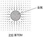
图2A中210表示的是当明线为裸金属线的情况下,低损耗约束表面波模式的横向电场在导线横截面上的强度和方向分布,其中箭头长度代表强度。该模式具有角向对称特性,且横截面上的电场方向沿着径向,垂直于金属表面,且强度沿着径向在靠近金属线的区域呈1/r的形式衰减,在远离金属线的区域则呈指数衰减。该模式最早由ArnoldSommerfeld提出,因此被称为索末菲波(Sommerfeld wave)。由于在金属线附近沿着径向呈1/r形式的衰减特性,类似于TEM模,索末菲波也可被称为准TEM模。索末菲波的等效折射率大于但非常接近于1,即传播波矢大于但非常接近于真空波矢k0,索末菲波在横截面上的衰减很慢,因此模式场很大,导致很小的传输损耗。作为一个例子,当金属线为材料为铜,半径为1cm时,索末菲波在10GHz和100GHz之间的欧姆损耗不超过-30dB/km,考虑到电线杆之间的距离通常为25m,因此该损耗可以忽略。210 in FIG. 2A represents the intensity and direction distribution of the transverse electric field of the low-loss confined surface wave mode on the cross section of the wire when the open wire is a bare metal wire, where the length of the arrow represents the intensity. This mode has angular symmetry, and the electric field direction on the cross section is along the radial direction, perpendicular to the metal surface, and the intensity decays along the radial direction in the form of 1/r in the area close to the metal wire, and in the area away from the metal wire The region decays exponentially. This mode was first proposed by Arnold Sommerfeld, so it is called the Sommerfeld wave. Similar to TEM modes, Sommerfeld waves may also be referred to as quasi-TEM modes due to the attenuation properties in the form of 1/r in the radial direction near the wire. The equivalent refractive index of the Sommerfeld wave is greater than but very close to 1, that is, the propagating wave vector is greater than but very close to the vacuum wave vector k0, the attenuation of the Sommerfeld wave in the cross section is very slow, so the mode field is large, resulting in small transmission loss. As an example, when the metal wire is made of copper and the radius is 1cm, the ohmic loss of the Sommerfeld wave between 10GHz and 100GHz does not exceed -30dB/km, considering that the distance between the poles is usually 25m, so This loss can be ignored.
裸金属线中的其他模式(比如HE10模式)的等效折射率小于1,属于辐射模式,这意味着,这些模式在沿着裸线传输的过程中将产生辐射而导致损耗。这种情况类似于电磁波在自由空间中传播,而这些辐射模式的发射和接收过程与通过天线发射和接收的过程相似,损耗取决于空间路损和天线增益。Other modes in the bare metal wire (such as the HE10 mode) have an equivalent refractive index less than 1 and belong to the radiation mode, which means that these modes will generate radiation and cause losses during transmission along the bare wire. This situation is analogous to electromagnetic waves propagating in free space, and the transmission and reception of these radiation patterns is similar to the process of transmission and reception through an antenna, the loss depends on the space path loss and antenna gain.
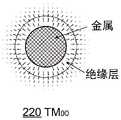
现在考虑当电力线为高保线120的情况。这种具有绝缘层的金属线缆由GeorgeJ.E.Goubau首先用于改善微波信号在金属线上的传输,因此称为高保线。Now consider the case when the power line is the
图2B表示的是TM00模式220的电场强度和方向分布,其中箭头的长度代表强度。TM00模式220与裸线中的索末菲波210的分布类似,具有角向对称特性,且电场方向沿径向,垂直于金属表面。Figure 2B shows the electric field strength and direction distribution of the
图2C表示的是HE10模式230的电场强度和方向分布,其中箭头的长度代表强度。HE10模式230与TM00模式220不同之处在于场分布沿着角向具有一个周期的振荡。除此之外,HE10模式230分布特性与TM00模式220基本相同,电场基本沿径向分布,且垂直于金属表面。Figure 2C shows the electric field strength and direction distribution of the
除了上述两种模式,高保线中还存在其它模式,在这里就不作赘述。In addition to the above two modes, there are other modes in the high security line, which will not be repeated here.
高保线的外绝缘层一般具有损耗,且在微波和毫米波频段,绝缘材料的介质损耗较大。作为一个非限定性实施例,明线为电力线,电线杆档距为25m,电力线常用的绝缘层材料聚乙烯的介电常数和损耗角正切分别为2和0.001。在30GHz,该材料本身的介质损耗为3.86dB/m。25m的损耗将接近-100dB。在绝缘层较厚,波长较短的情况下,高保线中的模式损耗将接近该数值。但是当载波频率接近高保线特定模式的截止频率时,模式场将逐渐脱离介质层而大量地分布在空气中(与索末菲波210具有相似的模式扩散特性),此时介质损耗对该近截止模式的传输影响变小。我们称这种表面波为弱约束表面波,这种频率接近截止频率的弱约束表面波具有很小的损耗,可用于信号在明线上的回传。比如当金属半径为1cm,聚乙烯绝缘层厚度为5mm时,频率处于17-20GHz时的TE01模式或者频率处于31-33GHz时的TM01模式就具有这种弱约束且低损特性。The outer insulating layer of the high-protection wire generally has loss, and in the microwave and millimeter-wave frequency bands, the dielectric loss of the insulating material is large. As a non-limiting example, the open wire is a power line, the pitch of the utility pole is 25m, and the dielectric constant and loss tangent of polyethylene, a commonly used insulating layer material for power lines, are 2 and 0.001, respectively. At 30GHz, the dielectric loss of the material itself is 3.86dB/m. The loss at 25m will be close to -100dB. In the case of thicker insulation and shorter wavelengths, the mode loss in high retention lines will be close to this value. However, when the carrier frequency is close to the cutoff frequency of the high-guaranteed specific mode, the mode field will gradually separate from the dielectric layer and distribute in the air in large quantities (similar to the mode diffusion characteristics of the Sommerfeld wave 210). The transmission effect of the cut-off mode becomes smaller. We call this kind of surface wave weakly confined surface wave, and the weakly confined surface wave whose frequency is close to the cutoff frequency has very little loss, and can be used for signal return on the open line. For example, when the metal radius is 1cm and the thickness of the polyethylene insulating layer is 5mm, the TE01 mode at a frequency of 17-20GHz or the TM01 mode at a frequency of 31-33GHz has such weak confinement and low loss characteristics.
具有多层绝缘层的明线中的模式与具有单层绝缘层的高保线中的模式类似,在接近截止频率时存在弱约束表面波。这些弱约束表面波模式的传输频率和场分布具有不确定性。对于不同的线缆,存在不同类型的弱约束表面波,因此把微波和毫米波信号从微基站耦合到电力线的耦合装置需要对特定明线中的特定弱约束表面波进行激励,即耦合装置需具有对待耦合模式的广泛适用性。Modes in open wires with multiple insulating layers are similar to those in high-retention wires with a single insulating layer, with weakly confined surface waves present near the cutoff frequency. The transmission frequencies and field distributions of these weakly confined surface wave modes are uncertain. For different cables, there are different types of weakly confined surface waves, so the coupling device that couples microwave and millimeter wave signals from the micro base station to the power line needs to excite the specific weakly confined surface wave in the specific open wire, that is, the coupling device needs to have Wide applicability of coupling modes to treat.
一般情况下,用于微基站间回传的弱约束表面波是低阶模式,比如裸金属线中的索末菲波210和高保线中的TM00模式220或者HE10模式230。当试图对这些低阶的弱约束表面波模式进行耦合,一个不可避免的问题是这些模式之间的模式简并效应,特别是当电力线尺寸较大的情况下(如半径D>λ)。明线中的模式简并指的是多种本征电磁模式的本征值和对应的传输常数很接近,在用传统的直接耦合方式进行激励时,会同时激励这些本征模式形成混合模式,而不能对其中指定的本征模式进行激励。图3A和B中展示的两种传统的表面波耦合方式将体现这种效应。In general, the weakly constrained surface waves used for backhaul between micro base stations are low-order modes, such as Sommerfeld waves 210 in bare metal wires and
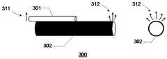
图3A示意图所示耦合器300采用的是波导直接耦合方式。波导直接耦合指的是利用两个相互靠近的波导中模式耦合作用使电磁波从一个波导中的模式耦合到另一个波导中的模式。在图3A中,来自主基站或微基站的微波或毫米波信号311通过介质波导301与明线302中的多种模式进行直接耦合结果激发出混合模式312。可以看出这种混合模式312具有非对称分布特性。事实上混合模式312并不是该种明线的本征模式,而是包含了多种本征表面波模式。这是由于这些低阶本征模式的本征值接近而存在简并。由于在特定的频段,只有指定的模式具有低损耗传输特性,因此混合模式312的存在必将导致传输能量的浪费。The
图3B示意图所示耦合器320采用的是利用几何光学进行端面耦合的方式。端面耦合指的是直接将电磁波照射到波导端面上,从而将该电磁波耦合到端面上与之匹配的指定模式。在图3B中,来自主基站或微基站的微波或毫米波信号311通过介质波导321和介质透镜322被聚焦到与明线呈45°放置的反射镜323的中心附近,通过反射镜323的反射,微波和毫米波信号与明线302中的多种表面波模式进行端面耦合形成混合模式332。同样地,混合模式332中包含了多种表面波本征模式,这是由于这些低阶本征模式存在简并而导致的。由于在特定的频段,只有指定的模式具有低损耗传输特性,因此混合模式332的存在必将导致传输能量的浪费。The
由于包含多种表面波本征模式,这种混合模式312和混合模式332在明线中进行传播时,在某些情况下还会存在串音现象。这种串音现象导致的原因是混合模式312和混合模式332中的多种表面波本征模式的本征值和传播常数很接近但是并非完全相等,因此这些本征模式在经过几千个波长的传输后相位差将发生变化,从而影响非对称混合模式312和混合模式332的分布。这种串音现象将对接收端的信号质量产生影响。Due to the inclusion of a variety of surface wave eigenmodes, when the
图3C示意图是一种串音现象的非限定性实施例。明线302是高保线,混合模式351主要集中在明线302的起始端的上方,可表示为两个本征模式352和353的同相叠加。由于本征模式352和353的传播常数存在略微的差异,经过几千个波长的传输之后,起始端的两个本征模式352和353分别转变为末端的本征模式355和356,此时本征模式355和356相位相反,叠加为混合模式354,该混合模式354主要集中在明线的下方。这种现象即为串音现象。假设表面波直接耦合装置300在明线起始端和末端都位于明线上方,可想而知,末端的混合模式354很难被耦合进末端的直接耦合装置中。Figure 3C is a schematic diagram of a non-limiting example of a crosstalk phenomenon. The
当然位于明线下方的混合模式354再传输一定距离以后通过相似的过程又可以转移到明线上方,但需要注意的是由于各个本征模式的传输常数不可知,混合模式351和354的沿明线302的分布很难被预测。因此,一旦明线302中存在串音,其导致的影响很难被消除。Of course, the
除图3C中所展示的缺点之外,对低阶弱约束表面波模式的直接耦合和端面耦合还存在弱耦合效应,以及由此导致的在工程上的非有效耦合。举高保线的例子来说,当金属线材料为铜,半径为1cm,绝缘层为聚乙烯,厚度为5mm时,在频率为20GHz时,TE01模式和HE11模式的传播常数相差约1%。如果直接用折射率接近两者等效折射率的泡沫材料组成介质波导进行耦合,就需要这种泡沫大批量加工时,其折射率的误差要小于1%,否则本来设计成耦合TE01模式的泡沫波导耦合出了HE11模式,从而影响了传输特性。In addition to the shortcomings shown in Figure 3C, there are weak coupling effects for direct coupling and end-face coupling of low-order weakly confined surface wave modes, and the resulting inefficient coupling in engineering. Taking the example of high protection wire, when the metal wire material is copper, the radius is 1cm, the insulating layer is polyethylene, and the thickness is 5mm, when the frequency is 20GHz, the difference between the propagation constants of TE01 mode and HE11 mode is about 1%. If the dielectric waveguide is directly composed of a foam material with a refractive index close to the equivalent refractive index of the two, it is necessary to process the foam in large quantities, and the error of the refractive index should be less than 1%, otherwise the foam originally designed to couple the TE01 mode The waveguide couples out the HE11 mode, which affects the transmission characteristics.
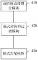
如图4A所示,本发明一实施例提供了一种耦合装置,包括:As shown in FIG. 4A, an embodiment of the present invention provides a coupling device, including:
高阶模直接耦合模块410,用于将来自发射器的第一电磁波耦合形成以预设高阶导波模式进行传播的第二电磁波;a high-order mode
模式转换和过滤模块420,用于将所述第二电磁波转换为以叠加的多个导波模式传播的第三电磁波,所述多个导波模式包括预设低阶导波模式和至少一个高阶导波模式,对所述第三电磁波中的高阶导波模式进行过滤获得以所述预设低阶导波模式传播的所述第四电磁波;The mode conversion and
模式匹配模块430,用于将所述第四电磁波转换为以目标导波模式沿明线表面传播的第五电磁波。The
本发明实施例提供的耦合装置,通过耦合到预设高阶导波模式再转换成预设低阶导波模式和多个高阶导波模式的叠加,并通过过滤获得预设低阶导波模式后再耦合到明线表面波,由于模式纯净度较高,因此,耦合时有效传输能量高,串音少。另外,在高阶模直接耦合模块410中耦合的是预设高阶波导模式,该预设高阶波导模式的模式独立性强(该预设高阶波导模式的传播常数或本征值与其附近模式的传播常数或本征值差异明显)。波导耦合需要参与耦合的波导各自的模式的传播常数一致以达到共振条件。相对于直接耦合处于简并状态的目标导波模式,对该预设高阶波导模式进行耦合时,参与耦合作用的波导的加工误差(包括材料误差和尺寸误差)导致的传输常数偏差不容易超过预设高阶模式与附近模式的传播常数之间的偏差,还可以保证预设高阶模式的模式纯净度。因此耦合到预设高阶导波模式,相比相关技术中的耦合方式,波导的加工误差对耦合效果影响较小。The coupling device provided by the embodiment of the present invention is coupled to a preset high-order guided wave mode and then converted into a preset low-order guided wave mode and a superposition of multiple high-order guided wave modes, and the preset low-order guided wave is obtained by filtering. The mode is then coupled to the open-line surface wave. Due to the high purity of the mode, the effective transmission energy during coupling is high and the crosstalk is low. In addition, what is coupled in the high-order mode
其中,目标导波模式为弱约束表面波模式,包括但不限于索末菲波、TM01模、EH11模、TE01模和HE11模等,可以根据需要设定目标导波模式。The target guided wave mode is a weakly constrained surface wave mode, including but not limited to Sommerfeld wave, TM01 mode, EH11 mode, TE01 mode, and HE11 mode, etc. The target guided wave mode can be set as required.
其中,预设高阶导波模式可以根据需要设定,比如为角向高阶模式,对金属同轴波导(表面覆盖金属层),指TEmn和TMmn中的角向波数指标m数值较大的模式;对表面覆盖绝缘层的同轴波导,指HEmn和EHmn中的角向波数指标m数值较大的模式。Among them, the preset high-order guided wave mode can be set as required, for example, it is an angular high-order mode, and for a metal coaxial waveguide (surface covered with a metal layer), it refers to the angular wavenumber index m in TEmn and TMmn with a larger value. Mode; for a coaxial waveguide covered with an insulating layer, it refers to the mode with a larger value of the angular wavenumber index m in HEmn and EHmn.
其中,预设低阶导波模式可以根据目标导波模式设定,比如为角向低阶模式,对金属同轴波导,指TEmn和TMmn中的角向波数指标m数值较小的模式,包括TEM模,对表面覆盖绝缘层的金属波导,指的是HEmn和EHmn中的角向波数指标m数值较小的情况;包括TM0n模和TE0n模。The preset low-order guided wave mode can be set according to the target guided wave mode, such as the angular low-order mode. For metal coaxial waveguides, it refers to the mode with a smaller value of the angular wavenumber index m in TEmn and TMmn, including TEM mode, for metal waveguides covered with insulating layer, refers to the case where the angular wavenumber index m in HEmn and EHmn is small; including TM0n mode and TE0n mode.
其中,预设高阶导波模式比如为角向高阶传导模式,多个导波模式比如为角向低阶传导模式和角向高阶截止模式的叠加,模式转换和过滤模块420对角向高阶截止模式进行衰减和反射,滤出角向低阶传导模式。传导模式指的是在波导传播方向具有传输特性的非截止模式,截止模式指的是在波导传输方向呈指数衰减的模式。The preset high-order guided wave mode is, for example, an angular high-order conduction mode, and the multiple guided wave modes are, for example, a superposition of an angular low-order conduction mode and an angular high-order cutoff mode. Higher-order cut-off modes are attenuated and reflected, filtering out angularly lower-order conduction modes. The conduction mode refers to a non-cut-off mode with transmission characteristics in the propagation direction of the waveguide, and the cut-off mode refers to a mode that decays exponentially in the propagation direction of the waveguide.
在一实施例中,所述高阶模直接耦合模块410包括互相靠近或紧贴的柱形波导和第一同轴波导,其中:所述柱形波导平行于所述第一同轴波导,且所述柱形波导的两个端面与所述第一同轴波导的两个端面分别对齐,所述第一同轴波导包裹所述明线。发射器通过一波导(比如介质波导)连接到柱形波导,发射器发射的电磁波通过波导传输到柱形波导(其传播模式通常为电磁波基模,比如TE11模式),通过直接耦合方式耦合到第一同轴波导中以预设高阶导波模式传播。由于波导中的导波模式取决于波导的形状和材料,因此,可以根据预设高阶导波模式确定第一同轴波导的尺寸和材质。In one embodiment, the high-order mode
在一实施例中,所述模式转换和过滤模块包括电磁性能参数在角向上呈周期分布的环栅和第二同轴波导,所述环栅位于所述第一同轴波导和所述第二同轴波导之间,其中,所述环栅的端面大小与所述第一同轴波导的端面一致,所述第二同轴波导的端面大小与所述第一同轴波导的端面大小一致,所述环栅的轴心与所述第一同轴波导、所述第二同轴波导的轴心一致,所述环栅和所述第二同轴波导包裹所述明线,所述环栅的端面靠近或紧贴所述第二同轴波导的端面;所述环栅的端面靠近或紧贴所述第一同轴波导的端面。需要说明的是,环栅的端面也可以大于第一同轴波导的端面。所述第二同轴波导根据需要过滤掉的高阶导波模式确定尺寸和材料。所述环栅比如为由扇形铜箔构成的在角向呈周期分布的金属光栅,所述第二同轴波导比如使用相对介电常数尽量小于第一同轴波导中填充的介质材料的相对介电常数并尽量接近于真空相对介电常数1的材料(空气和泡沫等)填充,使得除预设低阶导波模式以外的高阶模式尽量截止,达到模式过滤效果。In one embodiment, the mode conversion and filtering module includes an encircled grid and a second coaxial waveguide with electromagnetic performance parameters periodically distributed in an angular direction, the encircled grid located on the first coaxial waveguide and the second coaxial waveguide. between coaxial waveguides, wherein the size of the end face of the encircling grid is consistent with the end face of the first coaxial waveguide, and the size of the end face of the second coaxial waveguide is consistent with the size of the end face of the first coaxial waveguide, The axis of the encircling grid is consistent with the axes of the first coaxial waveguide and the second coaxial waveguide, the encircling grid and the second coaxial waveguide wrapping the open wire, and the The end face is close to or close to the end face of the second coaxial waveguide; the end face of the encircling grid is close to or close to the end face of the first coaxial waveguide. It should be noted that the end face of the encircling grid may also be larger than the end face of the first coaxial waveguide. The size and material of the second coaxial waveguide are determined according to the high-order guided wave modes that need to be filtered out. The encircling grating is, for example, a metal grating composed of fan-shaped copper foil with periodic distribution in the angular direction. Fill with materials (air and foam, etc.) whose electric constant is as close to the vacuum
在一实施例中,所述环栅的周期数根据所述预设高阶导波模式和所述目标导波模式确定。比如可以通过所述预设高阶导波模式的角向指标数减去所述目标导波模式角向指标数的方式确定环栅的周期数。In one embodiment, the number of periods of the encircling grid is determined according to the preset high-order guided wave mode and the target guided wave mode. For example, the number of periods of the surrounding grating may be determined by subtracting the angular index number of the target guided wave mode from the angular index number of the preset high-order guided wave mode.
在一实施例中,所述电磁性能参数包括以下至少之一:透射率、相位差。比如,环栅的透明度呈4个周期变化,又比如,环栅上相邻两区域的相位相反。In one embodiment, the electromagnetic performance parameters include at least one of the following: transmittance and phase difference. For example, the transparency of the gate all around changes in 4 cycles, and for another example, the phases of two adjacent regions on the gate all around are opposite.
在一实施例中,所述柱形波导的表面为绝缘层或者为金属层,即为由介质组成的介质波导,或者,内部为介质,表面覆盖金属层的空腔波导;所述第一同轴波导的表面为绝缘层或者为金属层,即内表面为金属层,中间为介质层,外表面为金属层,或者,只有内表面的金属层和介质层;所述第二同轴波导的表面为金属层,即内表面为金属层,中间为介质层,外表面为金属层。需要说明的是,当柱形波导表面为金属层、第一同轴波导的表面为金属层时,柱形波导和第一同轴波导的彼此靠近的区域均存在开槽。In an embodiment, the surface of the cylindrical waveguide is an insulating layer or a metal layer, that is, a dielectric waveguide composed of a medium, or a cavity waveguide with a medium inside and a surface covered with a metal layer; the first same The surface of the coaxial waveguide is an insulating layer or a metal layer, that is, the inner surface is a metal layer, the middle is a dielectric layer, and the outer surface is a metal layer, or only the inner surface of the metal layer and the dielectric layer; the second coaxial waveguide has a The surface is a metal layer, that is, the inner surface is a metal layer, the middle is a dielectric layer, and the outer surface is a metal layer. It should be noted that when the surface of the columnar waveguide is a metal layer and the surface of the first coaxial waveguide is a metal layer, there are grooves in the regions of the columnar waveguide and the first coaxial waveguide that are close to each other.
在以上实施例中,柱形波导、第一同轴波导、环栅和第二同轴波导的金属层可为铜箔、铝箔、金箔和银箔等,介质层可为聚乙烯(PE)、聚四氟乙烯(PTFE)、特氟龙(Teflon)、全氟乙烯丙烯共聚物(FEP)、乙烯-四氟乙烯共聚物(ETFE)、和陶瓷等微波和毫米波频段常用的介质材料。其中第二同轴波导中的介质层材料的介电常数小于第一同轴波导中的介质层材料并尽量接近1,也可为泡沫和空气。In the above embodiments, the metal layers of the cylindrical waveguide, the first coaxial waveguide, the encircling grid and the second coaxial waveguide can be copper foil, aluminum foil, gold foil, silver foil, etc., and the dielectric layer can be polyethylene (PE), Polytetrafluoroethylene (PTFE), Teflon (Teflon), perfluoroethylene propylene copolymer (FEP), ethylene-tetrafluoroethylene copolymer (ETFE), and ceramics are commonly used dielectric materials in microwave and millimeter wave frequency bands. The dielectric constant of the dielectric layer material in the second coaxial waveguide is smaller than that of the dielectric layer material in the first coaxial waveguide and as close to 1 as possible, and can also be foam and air.
在一实施例中,所述模式匹配模块将所述第四电磁波转换为以目标导波模式沿明线表面传播的第五电磁波包括:所述模式匹配模块将所述第四电磁波转换为沿平行于所述明线的方向传播的第五电磁波。即将第四电磁波转换为与明线平行的波束,模式匹配模块仅仅改变第四电磁波的传播方向,因此,预设低阶导波模式和目标导波模式之间存在一定的关联关系,比如,目标导波模式为索末菲波或者TM00模式时,预设低阶导波模式为TEM模式,又比如,目标导波模式为HE10模式时,预设低阶导波模式为TE10模式,又比如,目标导波模式为HE20模式时,预设低阶导波模式为TE20模式等等。In one embodiment, the mode matching module converting the fourth electromagnetic wave into a fifth electromagnetic wave propagating along the surface of the bright line in the target guided wave mode includes: The fifth electromagnetic wave propagates in the direction of the bright line. That is, the fourth electromagnetic wave is converted into a beam parallel to the open line, and the mode matching module only changes the propagation direction of the fourth electromagnetic wave. Therefore, there is a certain correlation between the preset low-order guided wave mode and the target guided wave mode. When the wave mode is Sommerfeld wave or TM00 mode, the preset low-order guided wave mode is TEM mode. For another example, when the target guided wave mode is HE10 mode, the preset low-order guided wave mode is TE10 mode. When the guided wave mode is HE20 mode, the default low-order guided wave mode is TE20 mode, etc.
在一实施例中,所述模式匹配模块包括角向对称的透镜,所述透镜包括用于容纳所述明线的圆柱形孔,所述透镜的轴心、所述圆柱形孔的轴心与所述第二同轴波导的轴心一致,所述透镜靠近所述第二同轴波导,远离所述环栅,且所述第二同轴波导远离所述环栅的端面位于所述透镜的焦平面上,所述透镜靠近所述第二同轴波导的端面的大小与所述第二同轴波导的端面大小一致。需要说明的是,所述透镜的端面也可以大于所述第二同轴波导的端面,且其在所述第二同轴波导的端面上的正投影完全覆盖所述第二同轴波导的端面。In one embodiment, the pattern matching module includes an angularly symmetric lens, the lens includes a cylindrical hole for accommodating the open wire, the axis of the lens, the axis of the cylindrical hole and the The axis of the second coaxial waveguide is the same, the lens is close to the second coaxial waveguide and away from the ring grid, and the end face of the second coaxial waveguide away from the ring grid is located at the focal point of the lens. On a plane, the size of the end face of the lens close to the second coaxial waveguide is the same as the size of the end face of the second coaxial waveguide. It should be noted that the end face of the lens can also be larger than the end face of the second coaxial waveguide, and its orthographic projection on the end face of the second coaxial waveguide completely covers the end face of the second coaxial waveguide .
在一实施例中,所述透镜为:远离所述第二同轴波导的端面凸起的透镜,或者菲涅尔透镜,或者菲涅尔波带片。透镜和菲涅尔透镜可采用聚乙烯(PE)、聚四氟乙烯(PTFE)、特氟龙(Teflon)、全氟乙烯丙烯共聚物(FEP)、乙烯-四氟乙烯共聚物(ETFE)、陶瓷和泡沫等在微波和毫米波频段常用的介质材料。菲涅尔波带片可由包括铜箔、铝箔、金箔和银箔等金属层构成。需要说明的是,上述第一同轴波导、第二同轴波导、环栅、透镜的内径与其所包裹的明线的外径一致或略大于所述明线的外径。In one embodiment, the lens is a lens with a convex end face away from the second coaxial waveguide, or a Fresnel lens, or a Fresnel zone plate. Lenses and Fresnel lenses can be made of polyethylene (PE), polytetrafluoroethylene (PTFE), Teflon (Teflon), perfluoroethylene propylene copolymer (FEP), ethylene-tetrafluoroethylene (ETFE), Dielectric materials commonly used in microwave and millimeter wave frequency bands such as ceramics and foams. The Fresnel zone plate can be composed of metal layers including copper foil, aluminum foil, gold foil, and silver foil. It should be noted that, the inner diameters of the first coaxial waveguide, the second coaxial waveguide, the ring grid, and the lens are the same as or slightly larger than the outer diameter of the bright wire wrapped with the outer diameter of the bright wire.
在一实施例中,所述第一电磁波为微波或毫米波信号。In one embodiment, the first electromagnetic wave is a microwave or millimeter wave signal.
另外,该耦合装置可包括一固定模块,用于固定该耦合装置各模块的位置,固定模块比如为覆盖在上述各模块外表面的泡沫层。In addition, the coupling device may include a fixing module for fixing the position of each module of the coupling device, and the fixing module is, for example, a foam layer covering the outer surface of the above-mentioned modules.
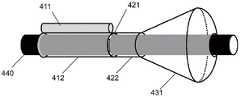
图4B是本发明一实施例提供的耦合装置示意图,如图4B所示,包括:FIG. 4B is a schematic diagram of a coupling device provided by an embodiment of the present invention, as shown in FIG. 4B , including:
由具有一定介电常数的介质填充的柱形波导411和包裹着明线的具有一定介电常数的介质填充的第一同轴波导412组成的高阶模直接耦合模块410。其中,柱形波导411和第一同轴波导412平行,且二者长度一致,柱形波导411和第一同轴波导412的两个端面分别对齐。第一同轴波导的材质和尺寸根据预设高阶导波模式决定。高阶模直接耦合模块410的作用是将所述柱形波导中的电磁波基模耦合到所述同轴波导中或者高保线中的角向高阶导波模式(即预设高阶导波模式)。在另一实施例中,柱形波导411和第一同轴波导412的长度也可不同。需要说明的是,图4B中所示的柱形波导411为圆形,在其他实施例中,柱形波导411也可是其他形状(比如方形等)。The high-order mode
由角向周期分布的环栅421和紧随其后的模式低通滤波导422(即第二同轴波导)组成的模式转换和过滤模块420。所述角向周期分布的环栅421的电磁性能参数(比如透射率和相位差)在角向上呈周期分布,环栅421的周期个数(或者称为拓扑荷)根据目标导波模式来确定。环栅421通过电磁性能参数的角向周期分布对所述高阶模直接耦合模块410中激发出来的角向高阶导波模式进行幅度和相位的角向周期调制从而转化成角向低阶导波模式和角向高阶截止模式的叠加,紧随其后的模式低通波导422对角向高阶截止模式进行衰减和反射,滤出角向低阶导波模式。The mode conversion and
径向空间调制结构431作为模式匹配模块430。径向空间调制结构431如介电常数沿角向对称、径向变化的材料,或者尺寸沿角向对称、径向变化的“类半球形”结构,又或者沿角向对称,径向呈周期性排列的光栅结构。所述径向空间调制结构431把所述经过模式转换和过滤模块420过滤的角向低阶导波模式转化为目标导波模式。The radial
需要说明的是,图4B仅为耦合装置的一示例,比如,在一实施例中,第一同轴波导412、环栅421、模式低通滤波波导422可以不包裹明线,而置于明线外,模式匹配模块430可以不是图4B中所示透镜,可以参考图3B所示结构,对来自模式低通滤波波导422的电磁波聚焦后,通过一反射镜发射到明线表面440。It should be noted that FIG. 4B is only an example of a coupling device. For example, in one embodiment, the first
另外,本实施例中,第一同轴波导412、环栅421、模式低通滤波波导422相邻的端面均形状大小一致,在另一实施例中,端面形状大小也可不一致。In addition, in this embodiment, the adjacent end faces of the first
由于模式转换和过滤模块可对除预设低阶导波模式外的高阶模式进行有效过滤,最终得到的导波模式比较纯净,因此可认为该耦合装置可实现对目标导波模式的高效激励。Since the mode conversion and filtering module can effectively filter the high-order modes except the preset low-order guided mode, the final guided mode is relatively pure, so it can be considered that the coupling device can realize the efficient excitation of the target guided mode .
根据无源装置的互易性,上述耦合装置也可以用于接收电磁波,将明线上的电磁波耦合到接收器。如图4C所示,本发明一实施例提供一种耦合装置,包括:According to the reciprocity of passive devices, the above-mentioned coupling device can also be used to receive electromagnetic waves, coupling the electromagnetic waves on the open wire to the receiver. As shown in FIG. 4C, an embodiment of the present invention provides a coupling device, including:
模式匹配模块440,用于将以目标导波模式传播的第六电磁波转换为以所述预设低阶导波模式传播的第七电磁波;a
模式转换和过滤模块450,用于将所述第七电磁波转换为以包括预设高阶导波模式的多个叠加的导波模式传播的第八电磁波,以及,对反射到所述模式匹配模块的高阶导波模式进行过滤;A mode conversion and
高阶模直接耦合模块460,用于将所述第八电磁波中以预设高阶导波模式传播的分量耦合到与接收器连接的波导。由波导将电磁波传送到接收器中。上述发射器和接收器可以设置在同一能进行发射和接收的设备中,比如微基站。The high-order mode
模式匹配模块440、模式转换和过滤模块450和高阶模直接耦合模块460的结构请分别参考前述实施例中的模式匹配模块430、模式转换和过滤模块420和高阶模直接耦合模块410,此处不再赘述。For the structures of the
需要说明的是,用于发射电磁波和用于接收电磁波的耦合装置也可以不同。It should be noted that the coupling devices for transmitting electromagnetic waves and for receiving electromagnetic waves may also be different.
如图5A所示,本发明一实施例提供一种表面波耦合方法,包括:As shown in FIG. 5A, an embodiment of the present invention provides a surface wave coupling method, including:
步骤501A,将来自发射器的第一电磁波耦合形成以预设高阶导波模式传播的第二电磁波;
步骤502A,将所述第二电磁波转换为以叠加的多个导波模式传播的第三电磁波,所述多个导波模式包括预设低阶导波模式和至少一个高阶导波模式,对所述第三电磁波中的高阶导波模式进行过滤获得以所述预设低阶导波模式传播的所述第四电磁波;
步骤503A,将所述第四电磁波转换为以目标导波模式沿明线表面传播的第五电磁波。
本发明实施例提供的耦合方法,将电磁波进行转换和过滤,获得比较纯净的导波模式再耦合到明线上,提高了有效传输能量,减少了串音。The coupling method provided by the embodiment of the present invention converts and filters the electromagnetic wave to obtain a relatively pure guided wave mode and couples it to the open line, thereby improving the effective transmission energy and reducing the crosstalk.
利用无源装置和系统的互易特性,图4A所示的耦合装置可用于接收,将明线上指定表面波模式耦合到接收器中。其中所利用的方法为图5A所示的方法的逆过程,如图5B所示,本发明一实施例提供一种表面波耦合方法,包括:Taking advantage of the reciprocity properties of passive devices and systems, the coupling device shown in Figure 4A can be used for reception, coupling a given surface wave mode on the open wire into the receiver. The method used is the inverse process of the method shown in FIG. 5A . As shown in FIG. 5B , an embodiment of the present invention provides a surface wave coupling method, including:
步骤501B,将明线表面以目标导波模式传播的第六电磁波转换为以所述预设低阶导波模式传播的第七电磁波;
步骤502B,将所述第七电磁波转换为以叠加的多个导波模式传播的第八电磁波,所述多个波导模式包括预设高阶导波模式,以及,对反射到所述模式匹配模块的高阶导波模式进行过滤;
步骤503B,将所述第八电磁波中以预设高阶导波模式传播的分量耦合到与接收器连接的波导。
下面通过应用实例对本发明实施例进行说明。The embodiments of the present invention will be described below through application examples.
应用实施例1:Application Example 1:
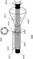
图6A是本发明提出的耦合装置的一个应用实施例。假设目标导波模式为裸金属线中的索末菲波210或高保线中的TM00模式220,耦合装置可由以下几部分构成:聚乙烯填充的金属空腔波导6101(即前述实施例中的柱形波导411)、聚乙烯填充的金属同轴波导6102(即第一同轴波导)、一块由金属(比如铜箔)构成的在角向上透明度呈4个周期变化的环栅6103、紧随环栅6103之后的由空气填充的金属同轴波导6104(即第二同轴波导)、由聚乙烯材料加工成的角向对称透镜6105和明线6106。其中聚乙烯填充的金属空腔波导6101和聚乙烯填充的金属同轴波导6102构成了高阶模直接耦合模块410;环栅6103和紧随其后的由空气填充的金属同轴波导6104构成了模式转换和过滤模块420;由聚乙烯材料加工成的角向对称透镜6105构成了模式匹配模块430。从基站或微基站中出来的微波和毫米波在该耦合装置中经历了以下几个过程:FIG. 6A is an application embodiment of the coupling device proposed by the present invention. Assuming that the target guided wave mode is the
在高阶模直接耦合模块410中,微波和毫米波经过介质波导(与基站或微基站连接)耦合到由聚乙烯填充的金属空腔波导6101中的主模TE11模式6111;通过直接模式耦合,金属空腔波导6101中TE11模式6111被转化成了聚乙烯填充的金属同轴波导6102中的TE40模式6112。该TE40模式6112是高阶模式,模式分立性很强。因此对该模式进行耦合,可以获得很好的模式纯净度,且填充材料聚乙烯的电性能参数和波导结构的加工误差对耦合效果影响较小。In the high-order mode
在模式转换和过滤模块420中,在经过透明度呈4个周期变化的环栅6103之后,同轴波导6102中的TE40模式6112转化为角向对称的TEM模和角向周期数为4的整数倍的高阶模,如TE40、TE80等等。除了TEM模式,其他模式都被设计成在由空气填充的同轴金属波导6104中的截止模式因而被反射回由聚乙烯填充的同轴金属波导6102中。在空气填充的同轴金属波导6104的出口处获得了纯净的角向对称的TEM模式6113。In the mode conversion and
在模式匹配模块430中,在经过空间滤波后的角向对称TEM模式6113在离开空气填充的同轴金属波导6104后在径向上会因为衍射而产生发散。通过将同轴金属波导6104的出口设置在由聚乙烯材料加工成的角向对称的透镜6105的焦平面上,经过透镜6105的聚焦反过程,TEM模式6113的径向发散波束转化为径向平行波束6114。最终,经过端面耦合,该径向平行波束6114将被耦合到明线6106上的指定的索末菲波210(裸线)或TM00模式220(高保线)。In the
应用实施例2:Application Example 2:
图6B是本发明提出的耦合装置的另一个应用实施例。假设目标导波模式仍然为裸金属线中的索末菲波210或高保线中的TM00模式220,耦合装置可由以下几部分构成:聚乙烯填充的金属空腔波导6201、聚乙烯填充的金属同轴波导6202、一块由铜箔构成的在角向上透明度呈4个周期变化的环栅6203、紧随环栅6203之后的由空气填充的金属同轴波导6204、带有聚乙烯支撑材料的角向对称的菲涅尔透镜或菲涅尔波带片6205和明线6206。其中聚乙烯填充的金属空腔波导6201和聚乙烯填充的金属同轴波导6202构成了高阶模直接耦合模块410;环栅6203和紧随其后的由空气填充的金属同轴波导6204构成了模式转换和过滤模块420;带有聚乙烯支撑材料的菲涅尔透镜或者菲涅尔波带片所构成的模块6205构成了模式匹配模块430。从基站和微基站中出来的微波和毫米波在该耦合装置中经历了以下几个过程:FIG. 6B is another application embodiment of the coupling device proposed by the present invention. Assuming that the target guided wave mode is still the
在高阶模直接耦合模块410中,微波和毫米波经过介质波导耦合到由聚乙烯填充的金属空腔波导6201中的主模TE11模式6211;通过直接模式耦合,金属空腔波导6201中TE11模式6211被转化成了聚乙烯填充的金属同轴波导6202中的TE40模式6212。该TE40模式6212是高阶模式,模式分立性很强。因此对该模式进行耦合,可以获得很好的模式纯净度,且填充材料聚乙烯的电性能参数和波导结构的加工误差对耦合效果影响较小。In the high-order mode
在模式转换和过滤模块420中,在经过透明度呈4个周期变化的环栅6203之后,同轴波导6202中的TE40模式6212转化为角向对称的TEM模和角向周期数为4的整数倍的高阶模,如TE40、TE80等等。除了TEM模式,其他模式都被设计成在由空气填充的同轴金属波导6204中的截止模式因而被反射回由聚乙烯填充的同轴金属波导6202中。结果在空气填充的同轴金属波导6204的出口处获得了纯净的角向对称的TEM模式6213。In the mode conversion and
在模式匹配模块430中,在经过空间滤波后的角向对称TEM模式6213在离开空气填充的同轴金属波导6204后在径向上会因为衍射而产生发散。通过将同轴金属波导6204的出口设置在带有聚乙烯支撑材料的菲涅尔透镜或者菲涅尔波带片6205的焦点上,利用菲涅尔透镜或者菲涅尔波带片6205的聚焦反过程,TEM模式6213的径向发散波束转化为径向平行波束6214。最终,经过端面耦合,该径向平行波束6214将被耦合到明线6206上的索末菲波210(明线6206为裸线时)或TM00模式220(明线6206为高保线时)。In the
应用实施例3:Application Example 3:
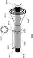
图6C是本发明的耦合装置的另一个应用实施例。假设目标导波模式为高保线中的HE10模式230,耦合装置可由以下几部分构成:聚乙烯填充的金属空腔波导6301、聚乙烯填充的金属同轴波导6302、一块由铜箔构成的在角向上透明度呈5个周期变化的环栅6303、紧随环栅6303之后的是由空气填充的金属同轴波导6304、由聚乙烯材料加工成的角向对称透镜6305和明线6206。其中聚乙烯填充的金属空腔波导6301和聚乙烯填充的金属同轴波导6302构成了高阶模直接耦合模块410;环栅6303和紧随其后的由空气填充的金属同轴波导6304构成了模式转换和过滤模块420;由聚乙烯材料加工成的角向对称透镜6305构成了模式匹配模块430。从基站和微基站中出来的微波和毫米波在该耦合装置中经历了以下几个过程:FIG. 6C is another application embodiment of the coupling device of the present invention. Assuming that the target guided wave mode is the
在高阶模直接耦合模块410中,微波和毫米波经过介质波导耦合到由聚乙烯填充的金属空腔波导6301中的主模TE11模式6311;通过直接模式耦合,金属空腔波导6301中TE11模式6311被转化成了聚乙烯填充的金属同轴波导6302中的TE40模式6312。该TE40模式6312是高阶模式,模式分立性很强。因此对该模式进行耦合,可以获得很好的模式纯净度,且填充材料聚乙烯的电性能参数和波导结构的加工误差对耦合效果影响较小。In the high-order mode
在模式转换和过滤模块420中,在经过透明度呈5个周期变化的环栅6303之后,同轴波导6302中的TE40模式6312转化为TE10、TE40和TE60等模式的叠加。除了TE10模式,其他模式都被设计成在由空气填充的同轴金属波导6304中的截止模式因而被反射回由聚乙烯填充的同轴金属波导6302中。结果在空气填充的同轴金属波导6304的出口处获得了纯净的TE10模式6313。In the mode conversion and
在模式匹配模块430中,在经过空间滤波后的TE10模式6313在离开空气填充的同轴金属波导6304后在径向上会因为衍射而产生发散。通过将同轴金属波导6304的出口设置在由聚乙烯材料加工成的角向对称的透镜6305的焦点上,利用透镜6305的聚焦反过程,TE10模式6313的径向发散波束转化为径向平行波束6314。最终,经过端面耦合,该径向平行波束6314将被耦合到明线6306上的指定HE10模式。In the
应用实施例4:Application Example 4:
图6D是本发明提供的耦合装置的另一个应用实施例。假设目标导波模式为高保线中的HE10模式230,耦合装置可由以下几部分构成:聚乙烯填充的金属空腔波导6401、聚乙烯填充的金属同轴波导6402、一块由铜箔构成的在角向上透明度呈5个周期变化的环栅6403、紧随环栅6403之后的是由空气填充的金属同轴波导6404、带有聚乙烯支撑材料的角向对称的菲涅尔透镜或菲涅尔波带片6405和明线6406。其中聚乙烯填充的金属空腔波导6401和聚乙烯填充的金属同轴波导6402构成了高阶模直接耦合模块410;环栅6403和紧随其后的由空气填充的金属同轴波导6404构成了模式转换和过滤模块420;带有聚乙烯支撑材料的角向对称的菲涅尔透镜或菲涅尔波带片6405构成了模式匹配模块430。从基站和微基站中出来的微波和毫米波在该耦合装置中经历了以下几个过程:FIG. 6D is another application embodiment of the coupling device provided by the present invention. Assuming that the target guided wave mode is the
在高阶模直接耦合模块410中,微波和毫米波经过介质波导耦合到由聚乙烯填充的金属空腔波导6401中的主模TE11模式6411;通过直接模式耦合,金属空腔波导6401中TE11模式6411被转化成了聚乙烯填充的金属同轴波导6402中的TE40模式6412。该TE40模式6412是高阶模式,模式分立性很强。因此对该模式进行耦合,可以获得很好的模式纯净度,且填充材料聚乙烯的电性能参数和波导结构的加工误差对耦合效果影响较小。In the high-order mode
在模式转换和过滤模块420中,在经过透明度呈5个周期变化的环栅6403之后,同轴波导6402中的TE40模式6412转化为TE10、TE40和TE60等模式的叠加。除了TE10模式,其他模式都被设计成在由空气填充的同轴金属波导6404中的截止模式因而被反射回由聚乙烯填充的同轴金属波导6402中。结果在空气填充的同轴金属波导6404的出口处获得了纯净的TE10模式6413。In the mode conversion and
在模式匹配模块430中,在经过空间滤波后的TE10模式6413在离开空气填充的同轴金属波导6404后在径向上会因为衍射而产生发散。通过将同轴金属波导6404的出口设置在菲涅尔透镜或者菲涅尔波带片6405的焦点上,利用所述菲涅尔透镜或者菲涅尔波带片6405的聚焦反过程,TE10模6413的径向发散波束转化为径向平行波束6414。最终,经过端面耦合,该径向平行波束6414将被耦合到明线6406上的指定HE10模式。In the
以上4个应用实施例只是对该耦合装置的几个示例性展示,而不是对该类装置的限制。所示的耦合装置都可以通过类似的方式实现对明线上其他指定表面波模式进行高效的激励。高阶模直接耦合模块中的空腔波导6101、6201、6301、6401和金属同轴波导6101、6202、6302、6402,以及在其中传输的TE11模式和TEm0模式并非是对该类耦合装置的限制。在一个实施例中,空腔波导6101、6201、6301、6401可为介质波导;在另一个实施例中,金属同轴波导6102、6202、6302、6402也可为由金属内壁和介质组成的同轴波导。The above four application embodiments are just a few exemplary representations of the coupling device, rather than a limitation of this type of device. The coupling devices shown can all achieve efficient excitation of other specified surface wave modes on the open wire in a similar manner. The
值得一提的是,高阶导波模式因在空气填充的金属同轴波导6104、6204、6304和6404中截止而产生反射,最终会在金属同轴波导6104、6204、6304和6404中产生回波损耗。同轴波导6102、6202、6302、6402和金属波导6101、6201、6301、6401类似于探针激励式同轴-波导转换结构中的背腔,调节它们的长度可以优化回波损耗。当然其它的如多节传输线或匹配电路也可以起到减小回波损耗的目的。It is worth mentioning that the higher-order guided-wave modes are reflected due to the cutoff in the air-filled metal
总的来说,通过先耦合到高阶导波模式,对该高阶导波模式进行转换和滤波,可以耦合出明线上目标导波模式(弱约束表面波模式),且该耦合方式可以解决由弱约束表面波模式简并效应导致的直接耦合方式中的非有效耦合。这种耦合方式特别适用于电力线直径较大(D>λ)的情况,考虑到真实的电力线通常半径较大,本申请提出的耦合装置和耦合方式具有较强的实用性。In general, by first coupling to the high-order guided wave mode, converting and filtering the high-order guided wave mode, the target guided wave mode (weakly constrained surface wave mode) on the open line can be coupled out, and this coupling method can solve the problem. Inefficient coupling in direct coupling mode due to weakly confined surface wave mode degeneracy effects. This coupling method is especially suitable for the case where the diameter of the power line is large (D>λ). Considering that the real power line usually has a large radius, the coupling device and the coupling method proposed in this application have strong practicability.
利用无源装置和系统的互易特性,以上4个实施例所示的耦合装置可用于接收,将明线上目标导波模式耦合到接收器中。其中所涉及的步骤为以上4个实施例所描述过程的逆过程,此处不再赘述。Taking advantage of the reciprocity characteristics of passive devices and systems, the coupling device shown in the above four embodiments can be used for reception, and the target guided wave mode on the open line is coupled into the receiver. The steps involved are the inverse processes of the processes described in the above four embodiments, which will not be repeated here.
解决了把微波和毫米波信号从基站和微基站中耦合到电力线上的问题,利用在明线上传输的低损的表面波模式,可以实现微波和毫米波信号在微基站之间的回传。在此基础之上,可以构建一套明线表面波无线网络覆盖系统。相较于传统的宏基站覆盖方案,明线表面波无线网络覆盖方案具有数据率高、有效覆盖范围广和部署容易等特点,将对5G通讯技术的发展和5G基站的部署起到积极的推动作用。It solves the problem of coupling microwave and millimeter wave signals from base stations and micro base stations to the power line. Using the low-loss surface wave mode transmitted on the open line, the backhaul of microwave and millimeter wave signals between micro base stations can be realized. On this basis, a set of open-line surface wave wireless network coverage system can be constructed. Compared with the traditional macro base station coverage scheme, the open-line surface wave wireless network coverage scheme has the characteristics of high data rate, wide effective coverage and easy deployment, which will play a positive role in promoting the development of 5G communication technology and the deployment of 5G base stations. .
应用实施例5:Application Example 5:
图7展示的是明线表面波无线网络覆盖方案的一个应用实施例。其中,本实施例中,明线为电力线。此时明线表面波无线网络覆盖方案可称为电力线无线网络覆盖方案。如图7所示,该系统包括一个主基站和若干微基站,以及多个耦合装置。首先考虑利用单根电力线进行回传的情况。在主路电线杆715上的主基站710被通讯地耦接到蜂窝网络的小区或因特网的一个站点中,其中的信号通过调制被加载在微波和毫米波信号上,主基站710通过波导连接到耦合装置711,通过耦合装置711被耦合到电力线上指定的弱约束表面波模式713(即目标导波模式)上,然后通过耦合装置721被耦合到支路电线杆727上的次级微基站720上(微基站720与耦合装置721之间由波导连接,后续微基站与耦合装置之间均存在波导连接,不再说明),微基站720对信号进行处理,从中提取部分信息转化为微波或毫米波信号728(比如WIFI信号)传送到该微基站720附近的用户设备729。被微基站720提取后的剩余信号被转化为微波和毫米波信号通过耦合装置723被耦合到指定的约束表面波模式725上,再经耦合装置731被传送至支路中的另一个次级微基站730。同样地,微基站730也对信号进行处理、提取,并通过转换成微波和毫米波信号738(比如WIFI信号)的方式将信息传送至附近的用户设备739。经微基站730提取后的剩余信息再一次被转化成微波和毫米波信号经过耦合装置733被耦合进入电力线中的指定弱约束表面波模式735并传输到下一个微基站。如此循环往复,微波和毫米信号就可以沿着电力线实现大范围的覆盖。由于电力线的部署一般会绕过建筑物,因此当微波和毫米信号沿着电力线传输时几乎不会遇到阻挡,这就解决了微波和毫米波宏基站覆盖中所遇到的建筑、山体、树林和隧道等大型障碍物的阻挡问题。同时,电力线本身可以为主基站710和次级微基站720、730等提供电源,且电线杆原本就已经部署好了,这都将有利于降低微波和毫米波基站的部署难度。FIG. 7 shows an application embodiment of the open-line surface wave wireless network coverage scheme. Wherein, in this embodiment, the open wire is a power wire. At this time, the open-line surface wave wireless network coverage scheme can be called a power line wireless network coverage scheme. As shown in Fig. 7, the system includes a main base station and several micro base stations, and a plurality of coupling devices. Consider first the case of backhauling with a single power line. The
值得一提的时,图7中713、714、725、726、735和736所表示的是弱约束表面波,并不是真实的表面波模式场的分布和方向。这些弱约束表面波模式可以是诸如图2中所指的索末菲波(裸金属线)和频率接近截止频率的表面波模式(高保线)中的任意一种。It is worth mentioning that 713, 714, 725, 726, 735 and 736 in Fig. 7 represent weakly confined surface waves, not the distribution and direction of the real surface wave mode field. These weakly confined surface wave modes may be any of Sommerfeld waves (bare metal wires) as referred to in Figure 2 and surface wave modes with frequencies close to the cutoff frequency (high-resistance wires).
在另一实施例中,主基站710可以不连接耦合装置,而是在电线杆715上部署一个微基站,主基站和微基站之间建立通信连接(有线或无线方式)。In another embodiment, the
图7中所指的电力线无线覆盖方案可以起到和宏覆盖基站同样的广覆盖的作用,区别是其接入天线分布在电线杆上,而不是集中在基站侧。因此该种覆盖方案也可称作电力线分布式天线覆盖方案。The power line wireless coverage scheme referred to in Figure 7 can play the same wide coverage role as the macro coverage base station, the difference is that its access antennas are distributed on the poles instead of being concentrated on the base station side. Therefore, this coverage scheme can also be referred to as a power line distributed antenna coverage scheme.
相比于AT&T推出的电力线无线网络覆盖方案,上述实施例中提供的明线表面波无线覆盖方案利用了纯净的指定表面波模式进行基站之间的回传,因此效率和可控性更高,更有利于成本的降低。相较于毫米波宏基站覆盖系统,该系统具有覆盖范围广、易部署等优势,对提升区域网络速度,特别是经济欠发达地区的区域网络速度将起到积极的作用。Compared with the power line wireless network coverage solution introduced by AT&T, the open-line surface wave wireless coverage solution provided in the above embodiment utilizes a pure specified surface wave mode for backhaul between base stations, so the efficiency and controllability are higher and more efficient. Conducive to cost reduction. Compared with the millimeter wave macro base station coverage system, the system has the advantages of wide coverage and easy deployment, which will play a positive role in improving the speed of regional networks, especially those in economically underdeveloped areas.
应用实施例6:Application Example 6:
利用单根电力线上的多种和多根电力线上的弱约束表面波模式,可以实现基站和微基站中微波和毫米波信号的多输入和多输出(即MIMO),从而扩展数据传输容量。Using multiple and weakly constrained surface wave modes on a single power line, multiple input and multiple output (ie, MIMO) of microwave and millimeter-wave signals in base stations and micro base stations can be implemented to expand data transmission capacity.
以两根电力线为例,在主路电线杆715上的主基站710被通讯地耦接到蜂窝网络的小区或因特网的一个站点中,其中的信号通过调制被加载在两路微波和毫米波信号上,通过耦合装置711和712被分别耦合到电力线上指定的弱约束表面波模式713和714上,然后分别通过耦合装置721和722被耦合到支路电线杆727上的次级微基站720上。此时,结合MIMO矢量解调算法,微基站720提取两路信号,转化为微波或毫米波信号728(比如WIFI信号)传送到该微基站720附近的用户设配729。被微基站720提取后的剩余信号经过MIMO矢量调制算法被转化为两路微波和毫米波信号,通过耦合装置723和724被分别耦合到指定的约束表面波模式725和726上,再经耦合装置731和732被传送至支路中的另一个次级微基站730。同样地,结合MIMO矢量解调算法,微基站730也对两路信号进行处理、提取,并通过转换成微波和毫米波信号738(比如WIFI信号)的方式将信息传送至附近的用户设备739。经微基站730提取后的剩余信息再一次被转化成两路微波和毫米波信号,经过耦合装置733和734被分别耦合进入电力线中的弱约束表面波模式735和736并传输到下一个微基站。该耦合方案要求两根电力线上的弱约束表面波模式之间具有比较高的隔离度,以保证MIMO矢量调制和解调算法的有效性。在常见的电线杆档距尺寸下,相邻电力线上的弱约束表面波模式之间的隔离度在大多数情况下可以满足MIMO矢量调制和解调算法的要求。Taking two power lines as an example, the
上一段展示了利用两根电力线上的弱约束表面波模式实现双路微波和毫米波信号进行回传的实施例,人们可以很自然地意识到,利用多根电力线和电力线中的多种正交模式,可以实现更多通道的输入和输出,从而进一步提高回传数据传输率。The previous paragraph shows an example of using weakly constrained surface wave modes on two power lines to achieve dual microwave and millimeter wave signals for backhaul, one can naturally realize that using multiple power lines and multiple orthogonal mode, more channels of input and output can be achieved, thereby further improving the return data transmission rate.
应用实施例7:Application Example 7:
图8是明线表面波无线网络覆盖的另一个应用实施例示意图。在该实施例中,明线表面波无线网络覆盖系统被用于铁路线路中。通过线路上包括为高铁、动车和地铁等提供电力的各种线缆,该系统可以为车厢中的乘客提供高速网络服务。如图8所示,铁路明线表面波无线网络覆盖系统800由通讯地耦接到车站810中的因特网和电路交换网节点的主基站820和多个次级微基站830、840等组成。主基站820从车站810的因特网和电路交换网节点中获取基带数据并通过收发链路转化为微波和毫米波信号。随后,第一个次级微基站830将该微波和毫米波信号部分地转化为无线信号834(同样在微波和毫米波频段),部分地通过耦合装置832耦合到明线上指定的约束表面波模式833。该约束表面波模式833经过耦合装置841将信号耦合到第二个次级微基站840中,被放大后,部分地转化为微波和毫米波频段的无线信号844。剩余的部分再一次通过耦合装置842耦合到指定的弱约束表面波模式843上。这样循环往复,就可以实现微波和毫米波信号在两个站点间铁道线路上的覆盖。列车850上安装的客户终端设备851(Customer Premise Equipment,简称CPE)在接收到由微基站发射的微波和毫米波无线信号834和844等后将其转化为诸如WIFI信号的无线信号并把该无线信号分布在列车内用于连接用户设备。FIG. 8 is a schematic diagram of another application embodiment of open-line surface wave wireless network coverage. In this embodiment, an open wire surface wave wireless network coverage system is used in a railway line. The system can provide high-speed Internet services to passengers in the carriages through various cables on the line that provide power for high-speed rail, high-speed trains, and subways. As shown in FIG. 8 , the railway open wire surface wave wireless
若以电线杆附近的区域作为小区的单位,则列车将在短时间内穿越多个小区的覆盖范围,引起频繁的小区间切换,将极大地降低网络性能,因此我们需要把这些小区合并,形成一个“超级小区”对一个较大的区域进行网络覆盖。If the area near the utility pole is used as the unit of the cell, the train will cross the coverage of multiple cells in a short time, causing frequent handovers between cells, which will greatly reduce the network performance. Therefore, we need to combine these cells to form A "super cell" provides network coverage over a larger area.
我们可以把两个车站间的整段铁路作为该“超级小区”的覆盖范围,即在两个车站间的整段铁路上,经微基站830、840等发送的无线信号834、844等以及在电力线上传输的弱约束表面波信号833和843等都是处于同一频段的同一种信号,该信号即主基站820所发送的微波和毫米波信号。微基站830和840等相当于直放站,只对该微波和毫米波信号进行如放大和功率分配之类的简单处理,一部分通过无线信号834和844等覆盖到铁路沿线,另一部分则被耦合到电力线上以用于下一段的覆盖。在这种情况下,高速列车850上的客户终端设备(CPE)851的收发频率范围也对应于主基站820发送的微波和毫米波频率范围。由于只起到微波和毫米波信号的中继作用,微基站的生产成本将显著降低,这将有助于降低整个网络的部署成本。We can take the entire section of the railway between the two stations as the coverage of the "super cell", that is, on the entire section of the railway between the two stations, the wireless signals 834, 844, etc. sent by the
同图7展示的常用电力线无线覆盖方案一样,铁路明线表面波无线覆盖方案也可以利用多根电力线实现弱约束表面波回传信号的多输入多输出(MIMO),这需要在微基站830、微基站840等中增加通道和求解MIMO的模块。Like the common power line wireless coverage scheme shown in Figure 7, the railway open-wire surface wave wireless coverage scheme can also use multiple power lines to achieve multiple-input multiple-output (MIMO) of weakly constrained surface wave return signals. Modules for adding channels and solving MIMO in the
本实施例利用铁路上的明线实现对列车的高速网络覆盖,这种方案将有效地提升高铁、动车和地铁车厢内用户的上网体验。In this embodiment, the open line on the railway is used to realize the high-speed network coverage of the train, and this solution will effectively improve the surfing experience of users in high-speed trains, high-speed trains, and subway cars.
图7和8中所展示的明线表面波无线覆盖方案的双工模式可以是时分双工(TimeDivision Duplexing,TDD),也可以是频分双工(Frequency Division Duplexing,FDD)。特别地,由于电力线上传输环境相对稳定,微基站表面波回传的双工模式可以选择全双工(Full-Duplex),进一步提高回传的数据传输速率。The duplex mode of the open-line surface wave wireless coverage scheme shown in FIGS. 7 and 8 may be Time Division Duplexing (TDD) or Frequency Division Duplexing (FDD). In particular, since the transmission environment on the power line is relatively stable, the duplex mode of the surface wave backhaul of the micro base station can be selected as Full-Duplex, which further improves the data transmission rate of the backhaul.
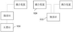
如图9所示,基于上述耦合装置,本发明一实施例提供一种明线表面波无线覆盖系统,包括至少一个微基站910,多个如任一实施例所述的耦合装置920,所述微基站910通过波导连接至至少一个所述耦合装置920,其中:As shown in FIG. 9 , based on the above coupling device, an embodiment of the present invention provides an open-line surface wave wireless coverage system, including at least one
所述微基站910用于,将载有信息的电磁波通过波导发送至与所述微基站910相连的耦合装置920,以及,从与所述微基站910相连的耦合装置920获取载有信息的电磁波;The
所述耦合装置920用于,将与所述耦合装置连接的微基站发送的载有信息的电磁波耦合到明线上以目标导波模式沿所述明线的表面传播,以及,将沿所述明线表面传播的载有信息的电磁波耦合到与所述耦合装置相连的微基站。The
在一实施例中,所述微基站910还用于,与终端建立连接,将从与所述微基站相连的所述耦合装置获取的载有信息的电磁波中提取信息下发给所述终端,以及,接收所述终端上传的信息并加载在电磁波上发送到与所述微基站相连的耦合装置。即将终端接入网络,上传或下载信息。In an embodiment, the
在一实施例中,所述明线表面波无线覆盖系统还包括主基站930,所述主基站930通过波导与至少一个所述耦合装置920相连(如图9所示),或者,所述主基站930与所述微基站910存在通信连接(如图10所示);In an embodiment, the open-wire surface wave wireless coverage system further includes a
所述主基站930用于,将信息加载在电磁波上通过波导发送到与所述主基站连接的耦合装置920,以及,接收来自与所述主基站相连的所述耦合装置的载有信息的电磁波;或者,将信息发送给微基站910,或从所述微基站910接收信息。The
在一实施例中,所述微基站910为中继站,即只对接收到的信号进行中继传输(进行基本的功率放大、功率分配等处理),微基站910相当于终端接入网络的中继设备,由主基站930对终端进行无线接入的控制和管理。In an embodiment, the
相比于传统的电力线表面波无线覆盖方案,本发明实施例提供的明线表面波无线覆盖方案用于回传的表面波模式可控性更高、可缓解由模式间干扰导致的接收功率恶化问题,且由于耦合装置只激励目标导波模式,激发效率更高。明线上激发的表面波模式性能的改善最终将提高基站间回传信号质量。Compared with the traditional power line surface wave wireless coverage solution, the open-line surface wave wireless coverage solution provided by the embodiment of the present invention has higher controllability of the surface wave mode used for backhaul, and can alleviate the problem of received power deterioration caused by inter-mode interference. , and because the coupling device only excites the target guided wave mode, the excitation efficiency is higher. The improvement in the performance of the surface wave modes excited on the open line will ultimately improve the backhaul signal quality between base stations.
尽管上文对本发明进行了详细说明,但是本发明不限于此,本技术领域技术人员可以根据本发明的原理进行各种修改。因此,凡按照本发明原理所作的修改,都应当理解为落入本发明的保护范围。Although the present invention has been described in detail above, the present invention is not limited thereto, and various modifications can be made by those skilled in the art in accordance with the principles of the present invention. Therefore, all modifications made in accordance with the principles of the present invention should be understood as falling within the protection scope of the present invention.
本领域普通技术人员可以理解,上文中所公开方法中的全部或某些步骤、系统、装置中的功能模块/单元可以被实施为软件、固件、硬件及其适当的组合。在硬件实施方式中,在以上描述中提及的功能模块/单元之间的划分不一定对应于物理组件的划分;例如,一个物理组件可以具有多个功能,或者一个功能或步骤可以由若干物理组件合作执行。某些组件或所有组件可以被实施为由处理器,如数字信号处理器或微处理器执行的软件,或者被实施为硬件,或者被实施为集成电路,如专用集成电路。这样的软件可以分布在计算机可读介质上,计算机可读介质可以包括计算机存储介质(或非暂时性介质)和通信介质(或暂时性介质)。如本领域普通技术人员公知的,术语计算机存储介质包括在用于存储信息(诸如计算机可读指令、数据结构、程序模块或其他数据)的任何方法或技术中实施的易失性和非易失性、可移除和不可移除介质。计算机存储介质包括但不限于RAM、ROM、EEPROM、闪存或其他存储器技术、CD-ROM、数字多功能盘(DVD)或其他光盘存储、磁盒、磁带、磁盘存储或其他磁存储装置、或者可以用于存储期望的信息并且可以被计算机访问的任何其他的介质。此外,本领域普通技术人员公知的是,通信介质通常包含计算机可读指令、数据结构、程序模块或者诸如载波或其他传输机制之类的调制数据信号中的其他数据,并且可包括任何信息递送介质。Those of ordinary skill in the art can understand that all or some of the steps in the methods disclosed above, functional modules/units in the systems, and devices can be implemented as software, firmware, hardware, and appropriate combinations thereof. In a hardware implementation, the division between functional modules/units mentioned in the above description does not necessarily correspond to the division of physical components; for example, one physical component may have multiple functions, or one function or step may be composed of several physical components Components execute cooperatively. Some or all components may be implemented as software executed by a processor, such as a digital signal processor or microprocessor, or as hardware, or as an integrated circuit, such as an application specific integrated circuit. Such software may be distributed on computer-readable media, which may include computer storage media (or non-transitory media) and communication media (or transitory media). As known to those of ordinary skill in the art, the term computer storage media includes both volatile and nonvolatile implemented in any method or technology for storage of information, such as computer readable instructions, data structures, program modules or other data flexible, removable and non-removable media. Computer storage media include, but are not limited to, RAM, ROM, EEPROM, flash memory or other memory technology, CD-ROM, digital versatile disk (DVD) or other optical disk storage, magnetic cartridges, magnetic tape, magnetic disk storage or other magnetic storage devices, or may Any other medium used to store desired information and which can be accessed by a computer. In addition, communication media typically embodies computer readable instructions, data structures, program modules, or other data in a modulated data signal such as a carrier wave or other transport mechanism, and can include any information delivery media, as is well known to those of ordinary skill in the art .
Claims (17)
Translated fromChinesePriority Applications (6)
| Application Number | Priority Date | Filing Date | Title |
|---|---|---|---|
| CN201811033366.3ACN110880947B (en) | 2018-09-05 | 2018-09-05 | Coupling device, surface wave coupling method, and open-line surface wave wireless coverage system |
| PCT/CN2019/082282WO2020048131A1 (en) | 2018-09-05 | 2019-04-11 | Coupling device, surface wave coupling method, and wireless coverage system employing surface wave of open wire |
| EP19858193.6AEP3849094B1 (en) | 2018-09-05 | 2019-04-11 | Coupling device, surface wave coupling method, and wireless coverage system employing surface wave of open wire |
| MYPI2021001193AMY205631A (en) | 2018-09-05 | 2019-04-11 | Coupling device, surface wave coupling method and open wire surface wave wireless coverage system |
| JP2021512752AJP7137693B2 (en) | 2018-09-05 | 2019-04-11 | Coupling device, surface wave coupling method and bare wire surface wave wireless coverage system |
| US17/192,900US11888547B2 (en) | 2018-09-05 | 2021-03-05 | Coupling device, surface wave coupling method and open wire surface wave wireless coverage system |
Applications Claiming Priority (1)
| Application Number | Priority Date | Filing Date | Title |
|---|---|---|---|
| CN201811033366.3ACN110880947B (en) | 2018-09-05 | 2018-09-05 | Coupling device, surface wave coupling method, and open-line surface wave wireless coverage system |
Publications (2)
| Publication Number | Publication Date |
|---|---|
| CN110880947A CN110880947A (en) | 2020-03-13 |
| CN110880947Btrue CN110880947B (en) | 2022-10-14 |
Family
ID=69722981
Family Applications (1)
| Application Number | Title | Priority Date | Filing Date |
|---|---|---|---|
| CN201811033366.3AActiveCN110880947B (en) | 2018-09-05 | 2018-09-05 | Coupling device, surface wave coupling method, and open-line surface wave wireless coverage system |
Country Status (6)
| Country | Link |
|---|---|
| US (1) | US11888547B2 (en) |
| EP (1) | EP3849094B1 (en) |
| JP (1) | JP7137693B2 (en) |
| CN (1) | CN110880947B (en) |
| MY (1) | MY205631A (en) |
| WO (1) | WO2020048131A1 (en) |
Families Citing this family (1)
| Publication number | Priority date | Publication date | Assignee | Title |
|---|---|---|---|---|
| CN112558217A (en)* | 2020-12-11 | 2021-03-26 | 中国科学院微电子研究所 | Electro-optical device and manufacturing method thereof |
Citations (6)
| Publication number | Priority date | Publication date | Assignee | Title |
|---|---|---|---|---|
| CN1478209A (en)* | 2000-10-09 | 2004-02-25 | ��������ķ������ | guided wave spatial filter |
| CN104914503A (en)* | 2015-06-23 | 2015-09-16 | 哈尔滨工程大学 | Terahertz wave tunable mode converter |
| CN105826639A (en)* | 2016-05-13 | 2016-08-03 | 电子科技大学 | TE10 mode-to-TE20 mode broadband mode converter of rectangular waveguide |
| CN106505280A (en)* | 2016-11-17 | 2017-03-15 | 山东省科学院海洋仪器仪表研究所 | A millimeter wave multi-frequency multi-mode excitation device |
| CN107005277A (en)* | 2014-10-21 | 2017-08-01 | At&T知识产权部有限合伙公司 | Guided wave delivery device with non-fundamental mode propagation and method of use |
| CN108196339A (en)* | 2018-01-08 | 2018-06-22 | 北京大学 | A kind of on piece mode multiplexing demultiplexes device |
Family Cites Families (27)
| Publication number | Priority date | Publication date | Assignee | Title |
|---|---|---|---|---|
| US7567154B2 (en)* | 2004-05-21 | 2009-07-28 | Corridor Systems, Inc. | Surface wave transmission system over a single conductor having E-fields terminating along the conductor |
| US9715988B2 (en)* | 2011-01-29 | 2017-07-25 | Calabazas Creek Research, Inc. | Gyrotron whispering gallery mode coupler with a mode conversion reflector for exciting a circular symmetric uniform phase RF beam in a corrugated waveguide |
| US8897697B1 (en) | 2013-11-06 | 2014-11-25 | At&T Intellectual Property I, Lp | Millimeter-wave surface-wave communications |
| US9209902B2 (en) | 2013-12-10 | 2015-12-08 | At&T Intellectual Property I, L.P. | Quasi-optical coupler |
| US9692101B2 (en) | 2014-08-26 | 2017-06-27 | At&T Intellectual Property I, L.P. | Guided wave couplers for coupling electromagnetic waves between a waveguide surface and a surface of a wire |
| US9564947B2 (en) | 2014-10-21 | 2017-02-07 | At&T Intellectual Property I, L.P. | Guided-wave transmission device with diversity and methods for use therewith |
| US9577306B2 (en) | 2014-10-21 | 2017-02-21 | At&T Intellectual Property I, L.P. | Guided-wave transmission device and methods for use therewith |
| US9520945B2 (en)* | 2014-10-21 | 2016-12-13 | At&T Intellectual Property I, L.P. | Apparatus for providing communication services and methods thereof |
| US9544006B2 (en)* | 2014-11-20 | 2017-01-10 | At&T Intellectual Property I, L.P. | Transmission device with mode division multiplexing and methods for use therewith |
| US9705561B2 (en) | 2015-04-24 | 2017-07-11 | At&T Intellectual Property I, L.P. | Directional coupling device and methods for use therewith |
| US10224981B2 (en) | 2015-04-24 | 2019-03-05 | At&T Intellectual Property I, Lp | Passive electrical coupling device and methods for use therewith |
| US9509415B1 (en) | 2015-06-25 | 2016-11-29 | At&T Intellectual Property I, L.P. | Methods and apparatus for inducing a fundamental wave mode on a transmission medium |
| US9640850B2 (en) | 2015-06-25 | 2017-05-02 | At&T Intellectual Property I, L.P. | Methods and apparatus for inducing a non-fundamental wave mode on a transmission medium |
| US10341142B2 (en)* | 2015-07-14 | 2019-07-02 | At&T Intellectual Property I, L.P. | Apparatus and methods for generating non-interfering electromagnetic waves on an uninsulated conductor |
| US20170047633A1 (en) | 2015-08-11 | 2017-02-16 | Keysight Technologies, Inc. | Signal transmission line and electrical connector including electrically thin resistive layer and associated methods |
| US10665942B2 (en)* | 2015-10-16 | 2020-05-26 | At&T Intellectual Property I, L.P. | Method and apparatus for adjusting wireless communications |
| US10044442B2 (en) | 2016-02-11 | 2018-08-07 | Google Llc | Quasi-wireless communication system |
| CA3026385A1 (en)* | 2016-06-10 | 2017-12-14 | At&T Intellectual Property I, L.P. | Backhaul link with reference signal for distributed antenna system |
| US10439675B2 (en)* | 2016-12-06 | 2019-10-08 | At&T Intellectual Property I, L.P. | Method and apparatus for repeating guided wave communication signals |
| US10446936B2 (en)* | 2016-12-07 | 2019-10-15 | At&T Intellectual Property I, L.P. | Multi-feed dielectric antenna system and methods for use therewith |
| US10205231B1 (en)* | 2017-09-06 | 2019-02-12 | At&T Intellectual Property I, L.P. | Antenna structure with hollow-boresight antenna beam |
| US10555318B2 (en)* | 2017-11-09 | 2020-02-04 | At&T Intellectual Property I, L.P. | Guided wave communication system with resource allocation and methods for use therewith |
| US10284261B1 (en)* | 2017-11-15 | 2019-05-07 | At&T Intellectual Property I, L.P. | Access point and methods for communicating with guided electromagnetic waves |
| US10200106B1 (en)* | 2018-03-26 | 2019-02-05 | At&T Intellectual Property I, L.P. | Analog surface wave multipoint repeater and methods for use therewith |
| US10405199B1 (en)* | 2018-09-12 | 2019-09-03 | At&T Intellectual Property I, L.P. | Apparatus and methods for transmitting or receiving electromagnetic waves |
| US10812136B1 (en)* | 2019-12-02 | 2020-10-20 | At&T Intellectual Property I, L.P. | Surface wave repeater with controllable isolator and methods for use therewith |
| US10886589B1 (en)* | 2019-12-02 | 2021-01-05 | At&T Intellectual Property I, L.P. | Guided wave coupling system for telephony cable messenger wire and methods for use therewith |
- 2018
- 2018-09-05CNCN201811033366.3Apatent/CN110880947B/enactiveActive
- 2019
- 2019-04-11WOPCT/CN2019/082282patent/WO2020048131A1/ennot_activeCeased
- 2019-04-11EPEP19858193.6Apatent/EP3849094B1/enactiveActive
- 2019-04-11JPJP2021512752Apatent/JP7137693B2/enactiveActive
- 2019-04-11MYMYPI2021001193Apatent/MY205631A/enunknown
- 2021
- 2021-03-05USUS17/192,900patent/US11888547B2/enactiveActive
Patent Citations (6)
| Publication number | Priority date | Publication date | Assignee | Title |
|---|---|---|---|---|
| CN1478209A (en)* | 2000-10-09 | 2004-02-25 | ��������ķ������ | guided wave spatial filter |
| CN107005277A (en)* | 2014-10-21 | 2017-08-01 | At&T知识产权部有限合伙公司 | Guided wave delivery device with non-fundamental mode propagation and method of use |
| CN104914503A (en)* | 2015-06-23 | 2015-09-16 | 哈尔滨工程大学 | Terahertz wave tunable mode converter |
| CN105826639A (en)* | 2016-05-13 | 2016-08-03 | 电子科技大学 | TE10 mode-to-TE20 mode broadband mode converter of rectangular waveguide |
| CN106505280A (en)* | 2016-11-17 | 2017-03-15 | 山东省科学院海洋仪器仪表研究所 | A millimeter wave multi-frequency multi-mode excitation device |
| CN108196339A (en)* | 2018-01-08 | 2018-06-22 | 北京大学 | A kind of on piece mode multiplexing demultiplexes device |
Also Published As
| Publication number | Publication date |
|---|---|
| EP3849094A4 (en) | 2021-11-03 |
| EP3849094A1 (en) | 2021-07-14 |
| US11888547B2 (en) | 2024-01-30 |
| CN110880947A (en) | 2020-03-13 |
| US20210266040A1 (en) | 2021-08-26 |
| WO2020048131A1 (en) | 2020-03-12 |
| JP7137693B2 (en) | 2022-09-14 |
| JP2021536189A (en) | 2021-12-23 |
| EP3849094B1 (en) | 2023-04-05 |
| MY205631A (en) | 2024-10-31 |
Similar Documents
| Publication | Publication Date | Title |
|---|---|---|
| US11063633B2 (en) | Guided wave transmission device with diversity and methods for use therewith | |
| CA2963969C (en) | Guided-wave transmission device with diversity and methods for use therewith | |
| US10536190B2 (en) | Guided-wave transmission device and methods for use therewith | |
| US10374319B2 (en) | Guided-wave transmission device with non-fundamental mode propagation and methods for use therewith | |
| CN107466430B (en) | Guided wave transmission device with non-fundamental mode propagation and method of use thereof | |
| CN110880947B (en) | Coupling device, surface wave coupling method, and open-line surface wave wireless coverage system |
Legal Events
| Date | Code | Title | Description |
|---|---|---|---|
| PB01 | Publication | ||
| SE01 | Entry into force of request for substantive examination | ||
| SE01 | Entry into force of request for substantive examination | ||
| GR01 | Patent grant | ||
| GR01 | Patent grant |