CN110874155A - Touch control device - Google Patents
Touch control deviceDownload PDFInfo
- Publication number
- CN110874155A CN110874155ACN201810995210.7ACN201810995210ACN110874155ACN 110874155 ACN110874155 ACN 110874155ACN 201810995210 ACN201810995210 ACN 201810995210ACN 110874155 ACN110874155 ACN 110874155A
- Authority
- CN
- China
- Prior art keywords
- electrodes
- touch
- electrode
- wire
- circuit layer
- Prior art date
- Legal status (The legal status is an assumption and is not a legal conclusion. Google has not performed a legal analysis and makes no representation as to the accuracy of the status listed.)
- Pending
Links
Images


Classifications
- G—PHYSICS
- G06—COMPUTING OR CALCULATING; COUNTING
- G06F—ELECTRIC DIGITAL DATA PROCESSING
- G06F3/00—Input arrangements for transferring data to be processed into a form capable of being handled by the computer; Output arrangements for transferring data from processing unit to output unit, e.g. interface arrangements
- G06F3/01—Input arrangements or combined input and output arrangements for interaction between user and computer
- G06F3/03—Arrangements for converting the position or the displacement of a member into a coded form
- G06F3/041—Digitisers, e.g. for touch screens or touch pads, characterised by the transducing means
- G06F3/044—Digitisers, e.g. for touch screens or touch pads, characterised by the transducing means by capacitive means
- G—PHYSICS
- G06—COMPUTING OR CALCULATING; COUNTING
- G06F—ELECTRIC DIGITAL DATA PROCESSING
- G06F3/00—Input arrangements for transferring data to be processed into a form capable of being handled by the computer; Output arrangements for transferring data from processing unit to output unit, e.g. interface arrangements
- G06F3/01—Input arrangements or combined input and output arrangements for interaction between user and computer
- G06F3/03—Arrangements for converting the position or the displacement of a member into a coded form
- G06F3/033—Pointing devices displaced or positioned by the user, e.g. mice, trackballs, pens or joysticks; Accessories therefor
- G06F3/0354—Pointing devices displaced or positioned by the user, e.g. mice, trackballs, pens or joysticks; Accessories therefor with detection of 2D relative movements between the device, or an operating part thereof, and a plane or surface, e.g. 2D mice, trackballs, pens or pucks
- G06F3/03547—Touch pads, in which fingers can move on a surface
- G—PHYSICS
- G06—COMPUTING OR CALCULATING; COUNTING
- G06F—ELECTRIC DIGITAL DATA PROCESSING
- G06F3/00—Input arrangements for transferring data to be processed into a form capable of being handled by the computer; Output arrangements for transferring data from processing unit to output unit, e.g. interface arrangements
- G06F3/01—Input arrangements or combined input and output arrangements for interaction between user and computer
- G06F3/03—Arrangements for converting the position or the displacement of a member into a coded form
- G06F3/041—Digitisers, e.g. for touch screens or touch pads, characterised by the transducing means
- G06F3/0412—Digitisers structurally integrated in a display
- G—PHYSICS
- G06—COMPUTING OR CALCULATING; COUNTING
- G06F—ELECTRIC DIGITAL DATA PROCESSING
- G06F3/00—Input arrangements for transferring data to be processed into a form capable of being handled by the computer; Output arrangements for transferring data from processing unit to output unit, e.g. interface arrangements
- G06F3/01—Input arrangements or combined input and output arrangements for interaction between user and computer
- G06F3/03—Arrangements for converting the position or the displacement of a member into a coded form
- G06F3/041—Digitisers, e.g. for touch screens or touch pads, characterised by the transducing means
- G06F3/0414—Digitisers, e.g. for touch screens or touch pads, characterised by the transducing means using force sensing means to determine a position
- H—ELECTRICITY
- H03—ELECTRONIC CIRCUITRY
- H03K—PULSE TECHNIQUE
- H03K17/00—Electronic switching or gating, i.e. not by contact-making and –breaking
- H03K17/94—Electronic switching or gating, i.e. not by contact-making and –breaking characterised by the way in which the control signals are generated
- H03K17/96—Touch switches
- H03K17/962—Capacitive touch switches
- G—PHYSICS
- G06—COMPUTING OR CALCULATING; COUNTING
- G06F—ELECTRIC DIGITAL DATA PROCESSING
- G06F2203/00—Indexing scheme relating to G06F3/00 - G06F3/048
- G06F2203/033—Indexing scheme relating to G06F3/033
- G06F2203/0339—Touch strips, e.g. orthogonal touch strips to control cursor movement or scrolling; single touch strip to adjust parameter or to implement a row of soft keys
Landscapes
- Engineering & Computer Science (AREA)
- General Engineering & Computer Science (AREA)
- Theoretical Computer Science (AREA)
- Human Computer Interaction (AREA)
- Physics & Mathematics (AREA)
- General Physics & Mathematics (AREA)
- Switches That Are Operated By Magnetic Or Electric Fields (AREA)
Abstract
Description
Translated fromChinese技术领域technical field
本发明涉及一种电子装置,尤其涉及一种触控装置。The present invention relates to an electronic device, in particular to a touch control device.
背景技术Background technique
现有的电子装置通过配备触控面板,以提供更直观且便利的触控操作功能。部分的触控装置还配备有控制钮(如旋钮),以让使用者在操作(如按压或旋转)时有实体的触感。现有的控制钮主要由导电材质(如金属)制成。通过使用者在操作时碰触控制钮所造成的电容变化来进行触控检测。在此架构下,使用者必须裸手操作(如按压或旋转)控制钮。换句话说,使用者若戴了手套(如毛料或塑料等不导电的手套)即无法操作控制钮。此外,由于金属材质容易导热,因此由金属材质制成的控制钮的温度容易受到环境影响。举例来说,若控制钮暴露于寒冷环境下,使用者在操作时会有冰冷的触感。另一方面,若控制钮被长时间曝晒,则使用者触摸控制钮可能会被烫伤。The existing electronic device is equipped with a touch panel to provide a more intuitive and convenient touch operation function. Some touch devices are also equipped with control buttons (such as knobs), so that the user can have a physical tactile sensation when operating (such as pressing or rotating). Existing control buttons are mainly made of conductive material (such as metal). The touch detection is performed by the capacitance change caused by the user touching the control button during operation. Under this architecture, the user must operate (eg, press or rotate) the control button with bare hands. In other words, the user cannot operate the control button if he wears gloves (eg, non-conductive gloves such as wool or plastic). In addition, since the metal material easily conducts heat, the temperature of the control knob made of the metal material is easily affected by the environment. For example, if the control button is exposed to a cold environment, the user may experience an icy tactile sensation when operating it. On the other hand, if the control button is exposed to the sun for a long time, the user may be burned by touching the control button.
发明内容SUMMARY OF THE INVENTION
本发明提供一种触控装置,其控制钮的温度不容易受到环境温度的影响,且使用者戴手套也可操作控制钮。The present invention provides a touch device, the temperature of the control button is not easily affected by the ambient temperature, and the user can also operate the control button wearing gloves.
根据本发明的实施例,触控装置包括控制钮以及触控面板。控制钮包括绝缘主体以及设置在绝缘主体上的导电件。触控面板设置在控制钮的一侧,且触控面板包括盖板以及触控元件。导电件位于绝缘主体与盖板之间。盖板位于导电件与触控元件之间。触控元件与导电件电性绝缘。触控元件包括对应控制钮设置的多个电极。导电件随着绝缘主体的作动而作动,且导电件的作动导致所述多个电极中的至少一个产生电容变化。According to an embodiment of the present invention, the touch control device includes a control button and a touch panel. The control button includes an insulating body and a conductive member arranged on the insulating body. The touch panel is arranged on one side of the control button, and the touch panel includes a cover plate and a touch element. The conductive member is located between the insulating body and the cover plate. The cover plate is located between the conductive element and the touch element. The touch element is electrically insulated from the conductive member. The touch element includes a plurality of electrodes corresponding to the control buttons. The conductive member is actuated with the actuation of the insulating body, and the actuation of the conductive member causes at least one of the plurality of electrodes to generate a capacitance change.
在根据本发明的实施例的触控装置中,导电件包括至少一个弹片,且控制钮还包括电路板。电路板位于导电件与触控面板之间。电路板包括电路基板、第一线路层以及第二线路层。电路基板具有第一表面以及第二表面。第二表面位于导电件与第一表面之间。第一线路层设置在第一表面上。第一线路层包括多个第一电极,且所述多个第一电极分别与触控元件的所述多个电极重叠。第二线路层设置在第二表面上且与第一线路层电性连接。绝缘主体的作动导致导电件与第二线路层接触。In the touch device according to the embodiment of the present invention, the conductive member includes at least one elastic piece, and the control button further includes a circuit board. The circuit board is located between the conductive member and the touch panel. The circuit board includes a circuit substrate, a first circuit layer and a second circuit layer. The circuit board has a first surface and a second surface. The second surface is located between the conductive member and the first surface. The first wiring layer is disposed on the first surface. The first circuit layer includes a plurality of first electrodes, and the plurality of first electrodes respectively overlap with the plurality of electrodes of the touch element. The second circuit layer is disposed on the second surface and is electrically connected with the first circuit layer. Action of the insulating body causes the conductive member to contact the second wiring layer.
在根据本发明的实施例的触控装置中,电路板不随绝缘主体的作动而作动。In the touch device according to the embodiment of the present invention, the circuit board does not act with the actuation of the insulating body.
在根据本发明的实施例的触控装置中,当绝缘主体被按压时,第一弹片接触第一导线以及第一接地线。当绝缘主体被旋转时,所述多个第二弹片分别接触第二导线以及第三导线,且所述多个第二弹片间歇地与所述多个导体部接触。In the touch device according to the embodiment of the present invention, when the insulating body is pressed, the first elastic piece contacts the first wire and the first ground wire. When the insulating body is rotated, the plurality of second elastic pieces contact the second wire and the third wire respectively, and the plurality of second elastic pieces intermittently contact the plurality of conductor parts.
在根据本发明的实施例的触控装置中,第二线路层包括多个第二电极。第二线路层的所述多个第二电极分别与第一线路层的所述多个第一电极重叠且电性连接。第一线路层还包括第一接地环。第二线路层还包括第二接地环。触控元件还包括第三接地环。第一接地环与第二接地环电性连接。第一接地环、第二接地环以及第三接地环彼此重叠。当绝缘主体被旋转时,所述至少一个弹片接触第二线路层的所述多个第二电极的其中一个以及第二接地环。In the touch device according to the embodiment of the present invention, the second circuit layer includes a plurality of second electrodes. The plurality of second electrodes of the second circuit layer respectively overlap and are electrically connected to the plurality of first electrodes of the first circuit layer. The first wiring layer also includes a first ground ring. The second wiring layer also includes a second ground ring. The touch element also includes a third ground ring. The first ground ring is electrically connected to the second ground ring. The first ground ring, the second ground ring, and the third ground ring overlap each other. When the insulating body is rotated, the at least one elastic piece contacts one of the plurality of second electrodes of the second circuit layer and the second ground ring.
在根据本发明的实施例的触控装置中,控制钮还包括多个限位部。所述多个限位部固定在第二表面上且沿着绝缘主体的周边设置。In the touch device according to the embodiment of the present invention, the control button further includes a plurality of limiting parts. The plurality of limiting portions are fixed on the second surface and arranged along the periphery of the insulating body.
在根据本发明的实施例的触控装置中,导电件包括导电垫。触控元件的所述多个电极包括多个信号电极以及多个接地电极。所述多个信号电极以及所述多个接地电极交替地沿着绝缘主体的圆周方向排列。导电垫的面积是每一个信号电极的面积的1.5倍到2倍,且导电垫的面积是每一个接地电极的面积的1.5倍到2倍。In the touch device according to the embodiment of the present invention, the conductive member includes a conductive pad. The plurality of electrodes of the touch element includes a plurality of signal electrodes and a plurality of ground electrodes. The plurality of signal electrodes and the plurality of ground electrodes are alternately arranged along the circumferential direction of the insulating body. The area of the conductive pad is 1.5 to 2 times the area of each signal electrode, and the area of the conductive pad is 1.5 to 2 times the area of each ground electrode.
在根据本发明的实施例的触控装置中,导电件包括导电垫。触控元件的所述多个电极包括多个驱动电极、多个感应电极以及多个接地电极。所述多个驱动电极、所述多个感应电极以及所述多个接地电极交替地沿着绝缘主体的圆周方向排列。导电垫的面积是每一个驱动电极的面积的2.5倍到3倍。导电垫的面积是每一个感应电极的面积的2.5倍到3倍。导电垫的面积是每一个接地电极的面积的2.5倍到3倍。In the touch device according to the embodiment of the present invention, the conductive member includes a conductive pad. The plurality of electrodes of the touch element includes a plurality of driving electrodes, a plurality of sensing electrodes and a plurality of ground electrodes. The plurality of driving electrodes, the plurality of sensing electrodes and the plurality of ground electrodes are alternately arranged along the circumferential direction of the insulating body. The area of the conductive pad is 2.5 to 3 times the area of each driving electrode. The area of the conductive pad is 2.5 times to 3 times the area of each sensing electrode. The area of the conductive pads is 2.5 to 3 times the area of each ground electrode.
在根据本发明的实施例的触控装置中,绝缘主体具有中心开孔,且中心开孔暴露出触控元件的所述多个电极中的至少一个。In the touch device according to the embodiment of the present invention, the insulating body has a central opening, and the central opening exposes at least one of the plurality of electrodes of the touch element.
在根据本发明的实施例的触控装置中,触控装置还包括显示元件,其中触控元件位于盖板与显示元件之间。In the touch control device according to the embodiment of the present invention, the touch control device further includes a display element, wherein the touch control element is located between the cover plate and the display element.
基于上述,在根据本发明的实施例的触控装置中,控制钮的主体采用绝缘材质制成。由于绝缘材质不容易导热,因此控制钮的温度不容易受到环境温度的影响,且使用者戴手套也可操作控制钮。Based on the above, in the touch device according to the embodiment of the present invention, the main body of the control button is made of insulating material. Since the insulating material does not conduct heat easily, the temperature of the control button is not easily affected by the ambient temperature, and the user can also operate the control button wearing gloves.
为让本发明的上述特征和优点能更明显易懂,下文特举实施例,并配合附图作详细说明如下。In order to make the above-mentioned features and advantages of the present invention more obvious and easy to understand, the following embodiments are given and described in detail with the accompanying drawings as follows.
附图说明Description of drawings
图1是根据本发明的第一实施例的触控装置的爆炸图;FIG. 1 is an exploded view of a touch device according to a first embodiment of the present invention;
图2A至图2D分别是图1中的第二线路层以及导电件在操作时的相对关系的正视图;2A to 2D are respectively front views of the relative relationship between the second circuit layer and the conductive member in FIG. 1 during operation;
图3是对应图2A至图2D的真值表的示意图;3 is a schematic diagram of the truth table corresponding to FIGS. 2A to 2D;
图4是图1中的触控元件的放大正视图;FIG. 4 is an enlarged front view of the touch element in FIG. 1;
图5是根据本发明的第二实施例的触控装置的爆炸图;5 is an exploded view of a touch device according to a second embodiment of the present invention;
图6是图5中的触控元件的放大正视图;FIG. 6 is an enlarged front view of the touch element in FIG. 5;
图7是根据本发明的第三实施例的触控装置的爆炸图;7 is an exploded view of a touch device according to a third embodiment of the present invention;
图8是图7中的第二线路层以及导电件在操作时的相对关系的正视图;FIG. 8 is a front view of the relative relationship between the second circuit layer and the conductive member in FIG. 7 during operation;
图9是根据本发明的第四实施例的触控装置的爆炸图。FIG. 9 is an exploded view of a touch device according to a fourth embodiment of the present invention.
具体实施方式Detailed ways
具体实施方式中所提到的方向用语,例如:“上”、“下”、“前”、“后”、“左”、“右”等,仅是参考附图的方向。因此,使用的方向用语是用来说明,而并非用来限制本发明。在附图中,各附图显示的是特定示范实施例中所使用的方法、结构和/或材料的通常性特征。然而,这些附图不应被解释为界定或限制由这些示范实施例所涵盖的范围或性质。举例来说,为了清楚起见,各膜层、区域和/或结构的相对厚度及位置可能缩小或放大。Directional terms mentioned in the detailed description, such as "up", "down", "front", "rear", "left", "right", etc., only refer to the directions of the drawings. Accordingly, the directional terms used are intended to illustrate rather than limit the present invention. In the drawings, each figure shows the general characteristics of methods, structures and/or materials used in particular exemplary embodiments. However, these drawings should not be construed to define or limit the scope or nature covered by these exemplary embodiments. For example, the relative thicknesses and positions of various layers, regions and/or structures may be reduced or exaggerated for clarity.
在具体实施方式中,相同或相似的元件将采用相同或相似的标号,且将省略其赘述。此外,不同示范实施例中的特征在没有冲突的情况下可相互组合,且依本说明书或权利要求书所作的等效变化与修饰,皆仍属本专利涵盖的范围内。另外,本说明书或权利要求书中提及的“第一”、“第二”等用语仅用以命名分立(discrete)的元件或区别不同实施例或范围,而并非用来限制元件数量上的上限或下限,也并非用以限定元件的制造顺序或设置顺序。In the specific implementation manner, the same or similar elements will be given the same or similar reference numerals, and repeated descriptions thereof will be omitted. In addition, the features of different exemplary embodiments may be combined with each other without conflict, and equivalent changes and modifications made in accordance with the present specification or claims are still within the scope of the present patent. In addition, terms such as "first" and "second" mentioned in this specification or the claims are only used to name discrete elements or to distinguish different embodiments or ranges, and are not used to limit the number of elements. The upper limit or the lower limit is not intended to limit the manufacturing order or the arrangement order of the elements.
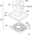
图1是根据本发明的第一实施例的触控装置1的爆炸图。请参见图1,触控装置1包括控制钮10以及触控面板20。控制钮10包括绝缘主体100以及导电件101。触控面板20设置在控制钮10的一侧且包括盖板200以及触控元件201。导电件101位于绝缘主体100与盖板200之间。盖板200位于导电件101与触控元件201之间,且触控元件201与导电件101电性绝缘。触控元件201包括对应控制钮10设置的多个电极(如电极S1、电极S2、电极S3、电极S4、电极GND1、电极GND2及电极GND3)。导电件101随着绝缘主体100的作动而作动,且导电件101的作动导致所述多个电极中的至少一个产生电容变化。FIG. 1 is an exploded view of a
详细来说,绝缘主体100是使用者在操作控制钮10时所碰触的元件。使用者对于控制钮10的操作可包括按压或旋转,对应地,绝缘主体100的作动可包括纵向上位移以及旋转。In detail, the insulating
绝缘主体100由绝缘材质制成。所述绝缘材质可包括塑胶,但不以此为限。由于绝缘材质不容易导热,因此控制钮10的温度不容易受到环境温度的影响。举例来说,操作处于寒冷环境中的控制钮10也不容易有冰冷的触感;操作被太阳长时间曝晒的控制钮10也不容易被烫伤。The insulating
绝缘主体100的形状可依据控制钮10的作动方式而设计。举例来说,若控制钮10的作动方式仅为纵向上位移(例如作为开关),则绝缘主体100的形状可为任意形状,如圆形、三角形、矩形或其他多边形。若控制钮10的作动方式包括旋转(例如作为控制温度、湿度、风速、音量等参数的控制元件),则绝缘主体100的形状可为圆形或其他具有指示性/方向性的形状。在本实施例中,绝缘主体100的形状为圆形,且绝缘主体100具有中心开孔1000。中心开孔1000贯穿绝缘主体100而适于暴露出位于绝缘主体100下的元件(容后说明)。The shape of the insulating
导电件101设置在绝缘主体100上。举例来说,导电件101可通过任何已知的方式(如黏着或焊接等方式)固定在绝缘主体100面向触控面板20的表面上。导电件101由导电材料制成。所述导电材料可包括金属,但不以此为限。在本实施例中,导电件101包括第一弹片1010以及多个第二弹片(如第二弹片1011以及第二弹片1012),且第一弹片1010比每一个第二弹片(包括第二弹片1011以及第二弹片1012)短。The conductive member 101 is provided on the insulating
在本实施例中,控制钮10还包括电路板102。电路板102位于导电件101与触控面板20之间。电路板102包括电路基板1020、第一线路层1021以及第二线路层1022。电路基板1020具有第一表面SF1以及第二表面SF2,且第二表面SF2位于导电件101与第一表面SF1之间。换句话说,第一表面SF1与第二表面SF2是电路基板1020的相对两表面,其中第一表面SF1面向触控面板20,且第二表面SF2面向导电件101。In this embodiment, the
第一线路层1021设置在第一表面SF1上。第一线路层1021包括多个第一电极(如第一电极S1A、第一电极S2A、第一电极S3A、第一电极GND1A及第一电极GND2A),且所述多个第一电极分别与触控元件201的所述多个电极重叠。详细来说,第一线路层1021的第一电极S1A与触控元件201的电极S1重叠。第一线路层1021的第一电极S2A与触控元件201的电极S2重叠。第一线路层1021的第一电极S3A与触控元件201的电极S3重叠。第一线路层1021的第一电极GND1A与触控元件201的电极GND1重叠。第一线路层1021的第一电极GND2A与触控元件201的电极GND2重叠。The
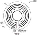
第二线路层1022设置在第二表面SF2上且与第一线路层1021电性连接。在本实施例中,第二线路层1022采用与第一线路层1021不同的线路设计。详细来说,第二线路层1022包括第一导线S1B、第二导线S2B、第三导线S3B、第一接地线GND1B以及第二接地线GND2B。第一导线S1B、第一接地线GND1B、第二导线S2B、第二接地线GND2B以及第三导线S3B可以同心圆的方式由内向外或由外向内依序排列。图1显示出由外向内依序排列的实施方式,但不以此为限。第一导线S1B、第二导线S2B、第三导线S3B以及第一接地线GND1B是连续的导线。第二接地线GND2B由多个导体部CP所组成,且所述多个导体部CP彼此分离。The
第一导线S1B通过电路基板1020内的线路(未示出)与第一线路层1021的第一电极S1A电性连接。第二导线S2B通过电路基板1020内的线路(未示出)与第一线路层1021的第一电极S2A电性连接。第三导线S3B通过电路基板1020内的线路(未示出)与第一线路层1021的第一电极S3A电性连接。第一接地线GND1B通过电路基板1020内的线路(未示出)与第一线路层1021的第一电极GND1A电性连接。第二接地线GND2B的多个导体部CP通过电路基板1020内的线路(未示出)与第一线路层1021的第一电极GND2A电性连接。The first wire S1B is electrically connected to the first electrode S1A of the
触控面板20的盖板200例如整面地覆盖在触控元件201上,而控制钮10可通过黏着层或其他固定元件而与触控面板20的盖板200固定在一起。如此,盖板200除了可保护位于其下的元件(如触控元件201)之外,位于盖板200上的导电元件/线路(如导电件101、第一线路层1021以及第二线路层1022)与位于盖板200下的元件/线路(如触控元件201)因为盖板200而结构上分离并且彼此电性绝缘。举例来说,盖板200可以是玻璃盖板或塑胶盖板,但不以此为限。For example, the
在本实施例中,触控面板20还可包括装饰层202。装饰层202设置在盖板200上,以遮蔽不欲被使用者看见的元件。详细来说,触控元件201除了多个电极(如电极S1、电极S2、电极S3、电极S4、电极GND1、电极GND2及电极GND3)之外,还可包括多条导线W以及多个接垫P。触控元件201的多个电极可分别通过至少一条导线W而与至少一个接垫P电性连接,以通过对应的至少一个接垫P与控制晶片(未示出)电性连接。这些导线W以及接垫P通常采用金属材质制作以具有理想的导电率。然而,金属材质不透光,容易影响显示效果。因此,可通过设置装饰层202来遮蔽这些导线W以及接垫P,来具有理想的显示效果及外观。In this embodiment, the
在本实施例中,装饰层202除了覆盖/遮蔽这些导线W以及接垫P之外还可覆盖/遮蔽电极S1、电极S2、电极S3、电极GND1及电极GND2。此外,装饰层202具有开口2020。开口2020与绝缘主体100的中心开孔1000重叠,且开口2020暴露出电极S4及电极GND3。详细来说,触控装置1可整合有显示元件(未示出),以在开口2020暴露出来的区域中显示信息。此外,通过绝缘主体100的中心开孔1000的设置,并在对应中心开孔1000/开口2020的区域设置电极S4及电极GND3,控制钮10的中心除了能显示信息之外还可提供触控操作功能。在此架构下,电极S4及电极GND3可采用透光的导电材质制作,以避免影响此区域的显示效果。所述透光的导电材质可包括金属氧化物,但不以此为限。In this embodiment, in addition to covering/shielding the wires W and the pads P, the
在本实施例中,触控元件201中的电极S1、电极S2、电极S3、电极GND1及电极GND2可用于检测绝缘主体100的作动方式。详细来说,电极S1与电极GND1连同长度较短的第一弹片1010可用于判断绝缘主体100是否被按压,而电极S2、电极S3及电极GND2连同长度较长的每一个第二弹片(包括第二弹片1011以及第二弹片1012)可用于判断绝缘主体100的旋转方式(如顺时针旋转或逆时针旋转)。图2A至图2D分别是图1中的第二线路层1022以及导电件101在操作时的相对关系的正视图。图3是对应图2A至图2D的真值表,其中真值表中的0代表产生信号变化(如电容变化),而真值表中的1代表未产生信号变化。In this embodiment, the electrode S1 , the electrode S2 , the electrode S3 , the electrode GND1 , and the electrode GND2 in the
请参见图1至图3,当绝缘主体100被按压时,长度较短的第一弹片1010以及长度较长的每一个第二弹片(包括第二弹片1011以及第二弹片1012)随着绝缘主体100一起被下压而碰触第二线路层1022,其中第一弹片1010接触第一导线S1B以及第一接地线GND1B(参见图2A),而使得触控元件201的电极S1对应产生信号变化(如电容变化),进而判断出绝缘主体100被按压。Referring to FIGS. 1 to 3 , when the insulating
当绝缘主体被旋转时,多个第二弹片(包括第二弹片1011以及第二弹片1012)分别接触第二导线S2B以及第三导线S3B,且所述多个第二弹片间歇地与所述多个导体部CP接触。举例来说,多个第二弹片的位置例如由图2A顺时针转至图2D。在本实施例中,控制钮10中随绝缘主体100作动(纵向上位移/旋转)的元件为导电件101,而电路板102不随绝缘主体100的作动而作动。因此在图2A至图2D中,仅导电件101(如第二弹片1011以及第二弹片1012)的位置改变,而第二线路层1022的位置不变。When the insulating body is rotated, the plurality of second elastic pieces (including the second
在图2A时,第二弹片1011接触第二导线S2B以及第二接地线GND2B的导体部CP,导致触控元件201的电极S2对应产生信号变化(如电容变化)。此外,第二弹片1012接触第三导线S3B以及第二接地线GND2B的导体部CP,导致触控元件201的电极S3对应产生信号变化。In FIG. 2A , the second
第二弹片1011以及第二弹片1012接着顺时针旋转而移动至图2B所示的位置。此时,第二弹片1011接触第二导线S2B但不接触第二接地线GND2B的导体部CP,因此触控元件201的电极S2不产生信号变化。另一方面,第二弹片1012仍接触第三导线S3B以及第二接地线GND2B的导体部CP,因此触控元件201的电极S3仍产生信号变化。The second
第二弹片1011以及第二弹片1012继续顺时针旋转而移动至图2C所示的位置。此时,第二弹片1011接触第二导线S2B但不接触第二接地线GND2B的导体部CP,且第二弹片1012接触第三导线S3B但不接触第二接地线GND2B的导体部CP。因此触控元件201的电极S2及电极S3皆不产生信号变化。The second
第二弹片1011以及第二弹片1012继续而移动至图2D所示的位置。此时,第二弹片1011接触第二导线S2B以及第二接地线GND2B的导体部CP,导致触控元件201的电极S2对应产生信号变化。另一方面,第二弹片1012仍接触第三导线S3B但不接触第二接地线GND2B的导体部CP因此触控元件201的电极S3仍不产生信号变化。The second
图3中的左半部显示出触控元件201的电极S2及电极S3对应图2A至图2D(即第二弹片由图2A顺时针旋转至图2D)的信号变化。图3中的右半部显示出触控元件201的电极S2及电极S3对应图2D至图2A(即第二弹片由图2D逆时针旋转至图2A)的信号变化。通过顺时针旋转及逆时针旋转所导致的时序信号变化差异(如图3所示),即可判断绝缘主体100的旋转方式(顺时针旋转或逆时针旋转)。在本实施例中,通过导电件101中的弹片接触第二线路层1022中的线路(导线/接地线),使第一线路层1021中相应的电极让触控元件201中相应的电极产生对地电容变化,从而实现自容式的触控感测。由于不是通过使用者的手接触导电主体所造成的电容变化去进行触控判断,因此使用者即使戴手套也可操作控制钮10。The left half of FIG. 3 shows the signal changes of the electrodes S2 and S3 of the
图4是图1中的触控元件201的放大正视图。请参见图4,触控元件201的电极S1、电极S2、电极S3、电极GND1以及电极GND2沿着绝缘主体100的圆周方向排列且被绝缘主体100(参见图4中的粗虚线)覆盖。电极S4以及电极GND3对应绝缘主体100的中心开孔1000设置而被电极S1、电极S2、电极S3、电极GND1以及电极GND2围绕。在本实施例中,电极GND1与电极GND2通过一条导线W电性连接,且电极GND3与电极GND1直接连接/接触。然而,触控元件201所包括的元件、各元件的数量以及触控元件201中的这些元件(如电极、导线W以及接垫P)的相对设置关系可依需求改变而不以图4所显示的为限。FIG. 4 is an enlarged front view of the
此外,触控元件201可形成在盖板200上。或者,触控元件201可先形成在额外的载板(未示出)上再贴附至盖板200。在一个实施例中,盖板200可为显示模块的对向基板(或彩色滤光基板),也就是说,触控元件201可形成于显示模块中,且控制钮10贴附至对向基板上,以形成内嵌式触控显示模块;替代地,触控元件201可形成在显示模块的对向基板的外表面上或形成在盖板200上,再依序将盖板200以及控制钮10贴附至显示模块,以形成外贴式触控显示模块。In addition, the
图5是根据本发明的第二实施例的触控装置1A的爆炸图。图6是图5中的触控元件201A的放大正视图。请参见图5及图6,触控装置1A与图1的触控装置1的主要差异如下所述。在触控装置1A中,控制钮10A的导电件101A以导电垫1013取代图1中的第一弹片1010、第二弹片1011以及第二弹片1012。此外,控制钮10A省略图1中的电路板102。另外,在触控面板20A中,触控元件201A包括多个信号电极S5以及多个接地电极GND。所述多个信号电极S5以及所述多个接地电极GND交替地沿着绝缘主体100的圆周方向排列。FIG. 5 is an exploded view of a
当绝缘主体100旋转时,导电垫1013会转至其中一个电极S5及其相邻的接地电极GND的上方,而导致所述其中一个电极S5产生对地电容变化。依据产生对地电容变化的电极S5的位置即可判断出导电垫1013的位置以及绝对角度,进而达到控制温度、湿度、风速、音量等参数的功能。When the insulating
当绝缘主体100旋转时,为了让导电垫1013能够覆盖其中一个信号电极S5及其对应的接地电极GND,导电垫1013的面积是每一个信号电极S5的面积的1.5倍到2倍,且导电垫1013的面积是每一个接地电极GND的面积的1.5倍到2倍。在本实施例中,电极S5的面积与接地电极GND的面积相同。When the insulating
触控元件201A中各电极的数量、形状以及触控元件201A中的这些元件(如电极、导线W以及接垫P)的相对设置关系可依需求改变,而不以图6所显示的为限。举例来说,可通过增加电极S5与接地电极GND的数量,来提升旋转控制的精密度。The number and shape of the electrodes in the
另应说明的是,触控元件201A的电极设计不限于自容感应的方式。在一个实施例中,触控元件201A可包括多个驱动电极、多个感应电极以及多个接地电极,以通过互容感应的方式实现触控检测。在此架构下,所述多个驱动电极、所述多个感应电极以及所述多个接地电极交替地沿着绝缘主体的圆周方向排列。此外,当绝缘主体旋转时,为了让导电垫能够覆盖其中一个驱动电极及其对应的感应电极以及接地电极,导电垫的面积是每一个驱动电极的面积的2.5倍到3倍,导电垫的面积是每一个感应电极的面积的2.5倍到3倍,且导电垫的面积是每一个接地电极的面积的2.5倍到3倍。It should also be noted that the electrode design of the
图7是根据本发明的第三实施例的触控装置1B的爆炸图。图8是图7中的第二线路层1022B以及导电件101B在操作时的相对关系的正视图。请参见图7及图8,触控装置1B与图1的触控装置1的主要差异如下所述。在触控装置1B中,控制钮10B的导电件101B只包括一个弹片1014。此外,第二线路层1022B包括多个第二电极S6。第二线路层1022B的所述多个第二电极S6分别与第一线路层1021B的所述多个第一电极S7重叠且电性连接。详细来说,在图1中,第二线路层1022采用与第一线路层1021不同的线路设计。在图7中,第二线路层1022B采用与第一线路层1021B相同或相似的线路设计。所述相同的线路设计是指第二线路层1022B的所述多个第二电极S6与第一线路层1021B的所述多个第一电极S7具有相同的图案、尺寸及元件相对设置位置。所述相似的线路设计是指第二线路层1022B的所述多个第二电极S6与第一线路层1021B的所述多个第一电极S7具有相同的元件相对设置位置,但电极的图案及尺寸可不相同。举例来说,第二电极S6的图案可为扇形,而第一电极S7的图案可为长方形。或者,第二电极S6的尺寸可大于或小于第一电极S7的尺寸。FIG. 7 is an exploded view of a touch device 1B according to a third embodiment of the present invention. FIG. 8 is a front view of the relative relationship between the
另外,触控元件201B包括多个电极S8,且触控元件201B的所述多个电极S8与第二线路层1022B的所述多个第二电极S6可具有相同或相似的图案、尺寸及元件相对设置位置。In addition, the touch element 201B includes a plurality of electrodes S8, and the plurality of electrodes S8 of the touch element 201B and the plurality of second electrodes S6 of the
在本实施例中,第一线路层1021B还包括第一接地环R1。第二线路层1022B还包括第二接地环R2。触控元件201B还包括第三接地环R3。第一接地环R1与第二接地环R2电性连接。此外,第一接地环R1、第二接地环R2以及第三接地环R3彼此重叠。详细而言,第一接地环R1例如设置在所述多个第一电极S7之间,且被所述多个第一电极S7环绕。第二接地环R2例如设置在所述多个第二电极S6之间,且被所述多个第二电极S6环绕。第三接地环R3设置在所述多个电极S8之间,且被所述多个电极S8环绕。然而,接地环的形状、数量及接地环与电极的相对设置关系可依需求改变而不以图7所显示的为限。In this embodiment, the
当绝缘主体100被旋转时,弹片1014接触第二线路层1022B的所述多个第二电极S6的其中一个以及第二接地环R2(参见图8),而导致触控元件201B中对应的电极S8产生对地电容变化。依据产生对地电容变化的电极S8的位置即可判断绝对旋转角度,进而达到准确控制温度、湿度、风速、音量等参数的功能。When the insulating
在本实施例中,控制钮10B还可包括多个限位部103B。所述多个限位部103B固定在第二表面SF2上且沿着绝缘主体100的周边设置,以限制绝缘主体100的位置,避免绝缘主体100在横向上产生位移。In this embodiment, the
图9是根据本发明的第四实施例的触控装置的爆炸图。请参见图9,触控装置1C与图7的触控装置1B的主要差异在于。触控装置1C还包括显示元件30,其中触控元件201B位于盖板200与显示元件30之间。显示元件30适于显示信息,其可采用任何已知的显示元件,如液晶显示元件、有机发光显示元件或微型发光二极管显示元件等,但不以此为限。在前述任一个实施例中,触控装置皆可依需求整合有显示元件30。FIG. 9 is an exploded view of a touch device according to a fourth embodiment of the present invention. Referring to FIG. 9 , the main difference between the
综上所述,在根据本发明的实施例的触控装置中,控制钮的主体采用绝缘材质制成。由于绝缘材质不容易导热,因此控制钮的温度不容易受到环境温度的影响。此外,使用者戴手套也可操作控制钮。在一个实施例中,可通过设置电路板并搭配对应的线路/电极设计来辨别控制钮的旋转角度,进而达到准确控制温度、湿度、风速、音量等参数的功能。在另一个实施例中,可通过导电件的导电垫与触控元件的电极的面积设计,来辨别控制钮的旋转角度,进而到准确控制温度、湿度、风速、音量等参数的功能且可省略电路板。To sum up, in the touch control device according to the embodiment of the present invention, the main body of the control button is made of insulating material. Since the insulating material does not conduct heat easily, the temperature of the control button is not easily affected by the ambient temperature. In addition, the user can operate the control buttons while wearing gloves. In one embodiment, the rotation angle of the control button can be identified by setting the circuit board and matching the corresponding circuit/electrode design, thereby achieving the function of accurately controlling parameters such as temperature, humidity, wind speed, and volume. In another embodiment, the area design of the conductive pad of the conductive member and the electrode of the touch element can be used to identify the rotation angle of the control button, and then the function of accurately controlling parameters such as temperature, humidity, wind speed, and volume can be omitted. circuit board.
最后应说明的是:以上各实施例仅用以说明本发明的技术方案,而非对其限制;尽管参照前述各实施例对本发明进行了详细的说明,本领域的普通技术人员应当理解:其依然可以对前述各实施例所记载的技术方案进行修改,或者对其中部分或者全部技术特征进行等同替换;而这些修改或者替换,并不使相应技术方案的本质脱离本发明各实施例技术方案的范围。Finally, it should be noted that the above embodiments are only used to illustrate the technical solutions of the present invention, but not to limit them; although the present invention has been described in detail with reference to the foregoing embodiments, those of ordinary skill in the art should understand that: The technical solutions described in the foregoing embodiments can still be modified, or some or all of the technical features thereof can be equivalently replaced; and these modifications or replacements do not make the essence of the corresponding technical solutions deviate from the technical solutions of the embodiments of the present invention. scope.
Claims (10)
Priority Applications (2)
| Application Number | Priority Date | Filing Date | Title |
|---|---|---|---|
| CN201810995210.7ACN110874155A (en) | 2018-08-29 | 2018-08-29 | Touch control device |
| US16/194,405US20200073492A1 (en) | 2018-08-29 | 2018-11-19 | Touch apparatus |
Applications Claiming Priority (1)
| Application Number | Priority Date | Filing Date | Title |
|---|---|---|---|
| CN201810995210.7ACN110874155A (en) | 2018-08-29 | 2018-08-29 | Touch control device |
Publications (1)
| Publication Number | Publication Date |
|---|---|
| CN110874155Atrue CN110874155A (en) | 2020-03-10 |
Family
ID=69639396
Family Applications (1)
| Application Number | Title | Priority Date | Filing Date |
|---|---|---|---|
| CN201810995210.7APendingCN110874155A (en) | 2018-08-29 | 2018-08-29 | Touch control device |
Country Status (2)
| Country | Link |
|---|---|
| US (1) | US20200073492A1 (en) |
| CN (1) | CN110874155A (en) |
Cited By (3)
| Publication number | Priority date | Publication date | Assignee | Title |
|---|---|---|---|---|
| CN113687740A (en)* | 2020-05-18 | 2021-11-23 | 杭州九阳小家电有限公司 | Capacitive touch sensing panel and electric appliance with same |
| TWI790787B (en)* | 2021-01-27 | 2023-01-21 | 奇景光電股份有限公司 | Knob device applicable to touch panel |
| TWI825485B (en)* | 2021-03-03 | 2023-12-11 | 奇景光電股份有限公司 | Knob device applicable to touch panel |
Families Citing this family (1)
| Publication number | Priority date | Publication date | Assignee | Title |
|---|---|---|---|---|
| US11460947B1 (en) | 2021-10-13 | 2022-10-04 | Himax Technologies Limited | Touch screen |
Citations (10)
| Publication number | Priority date | Publication date | Assignee | Title |
|---|---|---|---|---|
| TW201115441A (en)* | 2009-10-27 | 2011-05-01 | Chunghwa Picture Tubes Ltd | Capacitive touch panel, display device with capacitive touch panel and manufacturing method of the same |
| CN103592993A (en)* | 2012-08-13 | 2014-02-19 | 纬创资通股份有限公司 | Knob control device and control method of touch panel |
| CN203445855U (en)* | 2013-09-24 | 2014-02-19 | 吴冬华 | Magnetic coupling touch control button of capacitive touch screen |
| JP2014109991A (en)* | 2012-12-04 | 2014-06-12 | Panasonic Corp | Touch panel, touch panel unit and electronic apparatus |
| CN104765492A (en)* | 2015-03-30 | 2015-07-08 | 惠州华阳通用电子有限公司 | Touch panel with knob on surface and function starting method |
| CN104793787A (en)* | 2015-03-30 | 2015-07-22 | 惠州华阳通用电子有限公司 | Touch screen with surface provided with button and function starting method |
| TW201608445A (en)* | 2014-08-29 | 2016-03-01 | 勝華科技股份有限公司 | Touch panel |
| CN106209054A (en)* | 2015-01-16 | 2016-12-07 | 亿城精密光电股份有限公司 | Combined type touch button and module thereof |
| CN106843591A (en)* | 2017-02-16 | 2017-06-13 | 京东方科技集团股份有限公司 | A kind of contact panel, its preparation method and touch control display apparatus |
| CN108415632A (en)* | 2018-03-15 | 2018-08-17 | 京东方科技集团股份有限公司 | Touch panel and push button |
- 2018
- 2018-08-29CNCN201810995210.7Apatent/CN110874155A/enactivePending
- 2018-11-19USUS16/194,405patent/US20200073492A1/ennot_activeAbandoned
Patent Citations (10)
| Publication number | Priority date | Publication date | Assignee | Title |
|---|---|---|---|---|
| TW201115441A (en)* | 2009-10-27 | 2011-05-01 | Chunghwa Picture Tubes Ltd | Capacitive touch panel, display device with capacitive touch panel and manufacturing method of the same |
| CN103592993A (en)* | 2012-08-13 | 2014-02-19 | 纬创资通股份有限公司 | Knob control device and control method of touch panel |
| JP2014109991A (en)* | 2012-12-04 | 2014-06-12 | Panasonic Corp | Touch panel, touch panel unit and electronic apparatus |
| CN203445855U (en)* | 2013-09-24 | 2014-02-19 | 吴冬华 | Magnetic coupling touch control button of capacitive touch screen |
| TW201608445A (en)* | 2014-08-29 | 2016-03-01 | 勝華科技股份有限公司 | Touch panel |
| CN106209054A (en)* | 2015-01-16 | 2016-12-07 | 亿城精密光电股份有限公司 | Combined type touch button and module thereof |
| CN104765492A (en)* | 2015-03-30 | 2015-07-08 | 惠州华阳通用电子有限公司 | Touch panel with knob on surface and function starting method |
| CN104793787A (en)* | 2015-03-30 | 2015-07-22 | 惠州华阳通用电子有限公司 | Touch screen with surface provided with button and function starting method |
| CN106843591A (en)* | 2017-02-16 | 2017-06-13 | 京东方科技集团股份有限公司 | A kind of contact panel, its preparation method and touch control display apparatus |
| CN108415632A (en)* | 2018-03-15 | 2018-08-17 | 京东方科技集团股份有限公司 | Touch panel and push button |
Cited By (4)
| Publication number | Priority date | Publication date | Assignee | Title |
|---|---|---|---|---|
| CN113687740A (en)* | 2020-05-18 | 2021-11-23 | 杭州九阳小家电有限公司 | Capacitive touch sensing panel and electric appliance with same |
| CN113687740B (en)* | 2020-05-18 | 2024-03-12 | 杭州九阳小家电有限公司 | Capacitive touch sensing plate and electric appliance with same |
| TWI790787B (en)* | 2021-01-27 | 2023-01-21 | 奇景光電股份有限公司 | Knob device applicable to touch panel |
| TWI825485B (en)* | 2021-03-03 | 2023-12-11 | 奇景光電股份有限公司 | Knob device applicable to touch panel |
Also Published As
| Publication number | Publication date |
|---|---|
| US20200073492A1 (en) | 2020-03-05 |
Similar Documents
| Publication | Publication Date | Title |
|---|---|---|
| US9733676B2 (en) | Touch panel and manufacturing method thereof | |
| TWI621975B (en) | Touch panel and electronic device | |
| US11068084B2 (en) | Input device | |
| CN110874155A (en) | Touch control device | |
| CN107210158A (en) | Input unit and the electronic equipment that make use of the input unit | |
| US20150234486A1 (en) | Touch panel and manufacturing method thereof | |
| US10804897B2 (en) | Touch-sensitive keypad control device | |
| US20130314347A1 (en) | Touch panel and input device using same | |
| JP2015535637A (en) | Touch panel and manufacturing method thereof | |
| TWI512698B (en) | Flat panel display device with touch screen | |
| KR20140143645A (en) | Touch sensor panel and method for manufacturing the same | |
| WO2014121735A1 (en) | Adhesive film and manufacturing method therefor, device having touchscreen, and touch point transfer method | |
| TWI717280B (en) | Capacitive touch button | |
| TWI486857B (en) | Touch module | |
| JP6392504B2 (en) | Control panel | |
| TW201716962A (en) | Touch panel | |
| CN203133801U (en) | Touch panel | |
| CN112130705B (en) | Touch structure, electronic device and driving method of touch structure | |
| CN111381735A (en) | Button-shaped sheet and touch panel | |
| TWM456541U (en) | Touch panel | |
| JP2012059168A (en) | Panel type input device | |
| TWI739073B (en) | Electric-heating apparatus and touch device therein | |
| Rodríguez-Machorro et al. | Development of capacitive touch interfaces | |
| WO2009139297A1 (en) | Electrostatic capacitance-type pointing device | |
| TWM452387U (en) | Touch control module |
Legal Events
| Date | Code | Title | Description |
|---|---|---|---|
| PB01 | Publication | ||
| PB01 | Publication | ||
| SE01 | Entry into force of request for substantive examination | ||
| SE01 | Entry into force of request for substantive examination | ||
| WD01 | Invention patent application deemed withdrawn after publication | ||
| WD01 | Invention patent application deemed withdrawn after publication | Application publication date:20200310 |