CN110869770A - Apparatus and method for processing sample containers - Google Patents
Apparatus and method for processing sample containersDownload PDFInfo
- Publication number
- CN110869770A CN110869770ACN201880045539.5ACN201880045539ACN110869770ACN 110869770 ACN110869770 ACN 110869770ACN 201880045539 ACN201880045539 ACN 201880045539ACN 110869770 ACN110869770 ACN 110869770A
- Authority
- CN
- China
- Prior art keywords
- sample
- housing
- rack
- clamp
- locator
- Prior art date
- Legal status (The legal status is an assumption and is not a legal conclusion. Google has not performed a legal analysis and makes no representation as to the accuracy of the status listed.)
- Granted
Links
Images


Classifications
- G—PHYSICS
- G01—MEASURING; TESTING
- G01N—INVESTIGATING OR ANALYSING MATERIALS BY DETERMINING THEIR CHEMICAL OR PHYSICAL PROPERTIES
- G01N35/00—Automatic analysis not limited to methods or materials provided for in any single one of groups G01N1/00 - G01N33/00; Handling materials therefor
- G01N35/02—Automatic analysis not limited to methods or materials provided for in any single one of groups G01N1/00 - G01N33/00; Handling materials therefor using a plurality of sample containers moved by a conveyor system past one or more treatment or analysis stations
- G01N35/026—Automatic analysis not limited to methods or materials provided for in any single one of groups G01N1/00 - G01N33/00; Handling materials therefor using a plurality of sample containers moved by a conveyor system past one or more treatment or analysis stations having blocks or racks of reaction cells or cuvettes
- B—PERFORMING OPERATIONS; TRANSPORTING
- B01—PHYSICAL OR CHEMICAL PROCESSES OR APPARATUS IN GENERAL
- B01L—CHEMICAL OR PHYSICAL LABORATORY APPARATUS FOR GENERAL USE
- B01L9/00—Supporting devices; Holding devices
- B01L9/06—Test-tube stands; Test-tube holders
- B—PERFORMING OPERATIONS; TRANSPORTING
- B01—PHYSICAL OR CHEMICAL PROCESSES OR APPARATUS IN GENERAL
- B01L—CHEMICAL OR PHYSICAL LABORATORY APPARATUS FOR GENERAL USE
- B01L9/00—Supporting devices; Holding devices
- B01L9/50—Clamping means, tongs
- G—PHYSICS
- G01—MEASURING; TESTING
- G01N—INVESTIGATING OR ANALYSING MATERIALS BY DETERMINING THEIR CHEMICAL OR PHYSICAL PROPERTIES
- G01N35/00—Automatic analysis not limited to methods or materials provided for in any single one of groups G01N1/00 - G01N33/00; Handling materials therefor
- G01N35/02—Automatic analysis not limited to methods or materials provided for in any single one of groups G01N1/00 - G01N33/00; Handling materials therefor using a plurality of sample containers moved by a conveyor system past one or more treatment or analysis stations
- G01N35/04—Details of the conveyor system
- B—PERFORMING OPERATIONS; TRANSPORTING
- B01—PHYSICAL OR CHEMICAL PROCESSES OR APPARATUS IN GENERAL
- B01L—CHEMICAL OR PHYSICAL LABORATORY APPARATUS FOR GENERAL USE
- B01L2200/00—Solutions for specific problems relating to chemical or physical laboratory apparatus
- B01L2200/02—Adapting objects or devices to another
- B01L2200/023—Adapting objects or devices to another adapted for different sizes of tubes, tips or container
- B—PERFORMING OPERATIONS; TRANSPORTING
- B01—PHYSICAL OR CHEMICAL PROCESSES OR APPARATUS IN GENERAL
- B01L—CHEMICAL OR PHYSICAL LABORATORY APPARATUS FOR GENERAL USE
- B01L2200/00—Solutions for specific problems relating to chemical or physical laboratory apparatus
- B01L2200/02—Adapting objects or devices to another
- B01L2200/025—Align devices or objects to ensure defined positions relative to each other
- B—PERFORMING OPERATIONS; TRANSPORTING
- B01—PHYSICAL OR CHEMICAL PROCESSES OR APPARATUS IN GENERAL
- B01L—CHEMICAL OR PHYSICAL LABORATORY APPARATUS FOR GENERAL USE
- B01L2200/00—Solutions for specific problems relating to chemical or physical laboratory apparatus
- B01L2200/08—Ergonomic or safety aspects of handling devices
- B01L2200/087—Ergonomic aspects
- B—PERFORMING OPERATIONS; TRANSPORTING
- B01—PHYSICAL OR CHEMICAL PROCESSES OR APPARATUS IN GENERAL
- B01L—CHEMICAL OR PHYSICAL LABORATORY APPARATUS FOR GENERAL USE
- B01L2200/00—Solutions for specific problems relating to chemical or physical laboratory apparatus
- B01L2200/18—Transport of container or devices
- B—PERFORMING OPERATIONS; TRANSPORTING
- B01—PHYSICAL OR CHEMICAL PROCESSES OR APPARATUS IN GENERAL
- B01L—CHEMICAL OR PHYSICAL LABORATORY APPARATUS FOR GENERAL USE
- B01L2300/00—Additional constructional details
- B01L2300/02—Identification, exchange or storage of information
- B01L2300/021—Identification, e.g. bar codes
- G—PHYSICS
- G01—MEASURING; TESTING
- G01N—INVESTIGATING OR ANALYSING MATERIALS BY DETERMINING THEIR CHEMICAL OR PHYSICAL PROPERTIES
- G01N35/00—Automatic analysis not limited to methods or materials provided for in any single one of groups G01N1/00 - G01N33/00; Handling materials therefor
- G01N35/00584—Control arrangements for automatic analysers
- G01N35/00722—Communications; Identification
- G01N35/00732—Identification of carriers, materials or components in automatic analysers
- G01N2035/00792—Type of components bearing the codes, other than sample carriers
- G01N2035/00801—Holders for sample carriers, e.g. trays, caroussel, racks
- G—PHYSICS
- G01—MEASURING; TESTING
- G01N—INVESTIGATING OR ANALYSING MATERIALS BY DETERMINING THEIR CHEMICAL OR PHYSICAL PROPERTIES
- G01N35/00—Automatic analysis not limited to methods or materials provided for in any single one of groups G01N1/00 - G01N33/00; Handling materials therefor
- G01N35/02—Automatic analysis not limited to methods or materials provided for in any single one of groups G01N1/00 - G01N33/00; Handling materials therefor using a plurality of sample containers moved by a conveyor system past one or more treatment or analysis stations
- G01N35/04—Details of the conveyor system
- G01N2035/0401—Sample carriers, cuvettes or reaction vessels
- G01N2035/0412—Block or rack elements with a single row of samples
- G01N2035/0413—Block or rack elements with a single row of samples moving in one dimension
- G—PHYSICS
- G01—MEASURING; TESTING
- G01N—INVESTIGATING OR ANALYSING MATERIALS BY DETERMINING THEIR CHEMICAL OR PHYSICAL PROPERTIES
- G01N35/00—Automatic analysis not limited to methods or materials provided for in any single one of groups G01N1/00 - G01N33/00; Handling materials therefor
- G01N35/02—Automatic analysis not limited to methods or materials provided for in any single one of groups G01N1/00 - G01N33/00; Handling materials therefor using a plurality of sample containers moved by a conveyor system past one or more treatment or analysis stations
- G01N35/04—Details of the conveyor system
- G01N2035/0401—Sample carriers, cuvettes or reaction vessels
- G01N2035/0418—Plate elements with several rows of samples
- G01N2035/0422—Plate elements with several rows of samples carried on a linear conveyor
Landscapes
- Chemical & Material Sciences (AREA)
- Health & Medical Sciences (AREA)
- Chemical Kinetics & Catalysis (AREA)
- Clinical Laboratory Science (AREA)
- General Health & Medical Sciences (AREA)
- Biochemistry (AREA)
- Physics & Mathematics (AREA)
- General Physics & Mathematics (AREA)
- Immunology (AREA)
- Pathology (AREA)
- Analytical Chemistry (AREA)
- Life Sciences & Earth Sciences (AREA)
- Automatic Analysis And Handling Materials Therefor (AREA)
Abstract
Description
Translated fromChinese相关申请的交叉引用CROSS-REFERENCE TO RELATED APPLICATIONS
本申请要求2017年6月16日提交的美国临时申请No.62/521,293的优先权,其公开内容全文并入本文。This application claims priority to US Provisional Application No. 62/521,293, filed June 16, 2017, the disclosure of which is incorporated herein in its entirety.
背景技术Background technique
在实验室环境中,样品容器(诸如样品管或样品杯)通常容纳样品或样本,以便利用一项或多项测试进行分析。在一些情况下,以使用样品容器的自动处理的方式进行一项或多项测试。在这种示例中,可以自动地、手动地或两者结合进行测试本身。在处理样品容器时,要注意保持样品的完整性,才能获得可靠和有用的测试结果。在一些情况下,使用用于处理样品容器的各种设备和方法来帮助保持和转运一个或多个样品容器。In a laboratory setting, a sample container, such as a sample tube or sample cup, typically holds a sample or sample for analysis using one or more tests. In some cases, one or more tests are performed using automated processing of sample containers. In such an example, the test itself may be performed automatically, manually, or a combination of both. When handling sample containers, care must be taken to maintain sample integrity in order to obtain reliable and useful test results. In some cases, various devices and methods for handling sample containers are used to assist in holding and transporting one or more sample containers.
虽然已经得出和使用多种样品容器处理设备和方法,但是据信在提交本公开之前还没有人得出或使用本文所述的一个或多个发明方面。While various sample container processing devices and methods have been derived and used, it is believed that one or more of the inventive aspects described herein had not been derived or used prior to filing this disclosure.
附图说明Description of drawings
虽然说明书以明确指出并清楚要求保护本公开的某些方面的权利要求作为结尾,但是据信通过以下结合附图对某些示例的描述,可以更好地理解本公开,在附图中相同的附图标号标识相同的元件,并且在附图中:While the specification concludes with claims that clearly point out and distinctly claim certain aspects of the disclosure, it is believed that the disclosure can be better understood from the following description of certain examples taken in conjunction with the accompanying drawings, in which the same The reference numbers identify the same elements, and in the drawings:
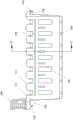
图1示出了用于保持一个或多个样品容器的示例性架的顶部透视图;Figure 1 shows a top perspective view of an exemplary rack for holding one or more sample containers;
图2示出了图1的架的底部透视图;Figure 2 shows a bottom perspective view of the rack of Figure 1;
图3示出了图1的架的分解透视图;Figure 3 shows an exploded perspective view of the rack of Figure 1;
图4示出了图1的架的后正视图;Figure 4 shows a rear elevational view of the rack of Figure 1;
图5示出了图1的架的侧部的局部透视图;Figure 5 shows a partial perspective view of the side of the rack of Figure 1;
图6示出了图5的架的侧部的局部透视图;Figure 6 shows a partial perspective view of the side of the rack of Figure 5;
图7示出了图1的架的另一侧部的局部透视图;Figure 7 shows a partial perspective view of another side of the rack of Figure 1;
图8示出了图7的架的侧部的局部透视图;Figure 8 shows a partial perspective view of the side of the rack of Figure 7;
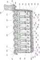
图9示出了图1的架的透视图,其被示出移除了壳体的一部分以显露内部组件;Figure 9 shows a perspective view of the rack of Figure 1 shown with a portion of the housing removed to reveal internal components;
图10示出了图1的架的夹具插入件的局部透视图;Figure 10 shows a partial perspective view of the clip insert of the rack of Figure 1;
图11示出了沿图4的线11—11截取的图1的架的横截面透视图;Figure 11 shows a cross-sectional perspective view of the rack of Figure 1 taken along line 11-11 of Figure 4;
图12示出了沿图4的线12—12截取的图1的架的横截面透视图;Figure 12 shows a cross-sectional perspective view of the rack of Figure 1 taken along line 12-12 of Figure 4;
图13示出了图1的架的壳体的后部部分的透视图;Figure 13 shows a perspective view of the rear portion of the housing of the rack of Figure 1;
图14示出了图1的架的壳体的前部部分的透视图;Figure 14 shows a perspective view of the front portion of the housing of the rack of Figure 1;
图15示出了图1的架的壳体的后部部分的透视图,其示出定位在架内的各种样式的测试管;Figure 15 shows a perspective view of the rear portion of the housing of the rack of Figure 1 showing various styles of test tubes positioned within the rack;
图16示出了图1的架的壳体的后部部分的前正视图;Figure 16 shows a front elevational view of the rear portion of the housing of the rack of Figure 1;
图17示出了沿图16的线17—17截取的图1的架的壳体的后部部分的横截面图;Figure 17 shows a cross-sectional view of the rear portion of the housing of the rack of Figure 1 taken along line 17-17 of Figure 16;
图18示出了图17的横截面图的放大视图;Figure 18 shows an enlarged view of the cross-sectional view of Figure 17;
图19示出了图1的架的一部分的放大透视图,其示出架保持示例性样品杯;19 shows an enlarged perspective view of a portion of the rack of FIG. 1 showing the rack holding an exemplary sample cup;
图20示出了用于保持一个或多个样品容器的另一示例性架的顶部透视图;Figure 20 shows a top perspective view of another exemplary rack for holding one or more sample containers;
图21示出了图20的架的底部透视图;Figure 21 shows a bottom perspective view of the rack of Figure 20;
图22示出了图20的架的分解透视图;Figure 22 shows an exploded perspective view of the rack of Figure 20;
图23示出了图15的架的分解图,其示出止动插入件的顶视图紧挨壳体的底视图;Figure 23 shows an exploded view of the rack of Figure 15 showing a top view of the stop insert next to a bottom view of the housing;
图24示出了图20的架的一部分的局部横截面图;Figure 24 shows a partial cross-sectional view of a portion of the rack of Figure 20;
图25示出了可与图1和图20的架一起使用的多个示例性样品杯;Figure 25 illustrates a number of exemplary sample cups that may be used with the racks of Figures 1 and 20;
图26示出了图20的架的透视图,其被示出各种样式的样品杯保持在其中;FIG. 26 shows a perspective view of the rack of FIG. 20 with sample cups shown in various styles held therein;
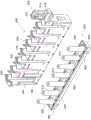
图27示出了安装在示例性样品分析仪的示例性样品呈现单元(SPU)中的第一位置处的图1的示例性架的透视图;27 shows a perspective view of the example rack of FIG. 1 installed in a first position in an example sample presentation unit (SPU) of an example sample analyzer;
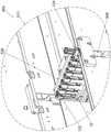
图28示出了图27中所示的图1的示例性架和示例性样品分析仪的示例性样品呈现单元(SPU)的透视图,但其中示例性架位于SPU的第二位置处;并且28 illustrates a perspective view of the exemplary rack of FIG. 1 and an exemplary sample presentation unit (SPU) of the exemplary sample analyzer shown in FIG. 27, but with the exemplary rack in a second position of the SPU; and
图29示出了图27中所示的图1的示例性架和示例性样品分析仪的示例性样品呈现单元(SPU)的透视图,但其中示例性架部分地移出图28所示的SPU的第二位置。29 shows a perspective view of the example rack of FIG. 1 and an example sample presentation unit (SPU) of the example sample analyzer shown in FIG. 27, but with the example rack partially removed from the SPU shown in FIG. 28 the second position.
附图并非旨在以任何方式进行限制,并且可以设想可以多种其他方式来实施本公开的各种实施方案,包括未必在附图中示出的那些方式。并入说明书并形成说明书的一部分的附图例示了本公开的若干方面,并且与说明书一起用于解释本公开的原理;应当理解,权利要求不限于所示的布置方式。The drawings are not intended to be limiting in any way, and it is contemplated that various embodiments of the disclosure may be practiced in various other ways, including those not necessarily shown in the drawings. The accompanying drawings, which are incorporated in and form a part of the specification, illustrate several aspects of the disclosure, and together with the description serve to explain the principles of the disclosure; it is to be understood that the claims are not limited to the arrangements shown.
具体实施方式Detailed ways
以下对本公开的某些示例的描述不应用于限制权利要求的范围。通过以下描述,本公开的其他示例、特征、方面、实施方案和优点对于本领域的技术人员将变得显而易见,以下描述以举例的方式包括设想用于实施本公开的某些方面的最佳模式。如将认识到的,本公开的某些方面能够具有其他不同且明显的实施方式,所有这些都不脱离本公开的原理。因此,附图和说明书在本质上应被视为例示性的而非限制性的。The following description of certain examples of the present disclosure should not be used to limit the scope of the claims. Other examples, features, aspects, embodiments, and advantages of the present disclosure will become apparent to those skilled in the art from the following description, which includes, by way of example, the best mode contemplated for carrying out certain aspects of the present disclosure . As will be realized, certain aspects of the present disclosure are capable of other different and obvious embodiments, all without departing from the principles of the present disclosure. Accordingly, the drawings and description are to be regarded as illustrative in nature and not restrictive.
本文可使用描述组件和特征部的取向(例如,竖直、底部、顶部等)的相对术语。这些术语可适用于其中使用各种组件和特征部的某些实施方案和/或环境。描述取向的术语也可方便地用于描述本文的各种组件、特征部和环境。根据本文的教导内容,其他实施方案和/或环境可包括本领域的普通技术人员将会理解的其他取向。Relative terms may be used herein to describe the orientation of components and features (eg, vertical, bottom, top, etc.). These terms may apply to certain embodiments and/or environments in which various components and features are used. The terms describing orientation are also conveniently used to describe various components, features, and environments herein. Other embodiments and/or environments may include other orientations as would be understood by one of ordinary skill in the art in light of the teachings herein.
I.用于样品容器处理的示例性架I. Exemplary Rack for Sample Container Handling
图1-19示出了用于保持一个或多个样品容器的示例性架(10)或其部分。样品容器被构造成保持样品或样本。在一些情况下,样品容器以样品管的形式构造。在一些其他情况下,样品容器以样品杯的形式构造。在图1-19的例示架(10)中,架(10)被构造成具有容纳各种大小的样品管的特征部。然而,架(10)的某些特征部还允许架(10)容纳样品杯。1-19 illustrate an exemplary rack (10) or portion thereof for holding one or more sample containers. The sample container is configured to hold a sample or samples. In some cases, the sample container is constructed in the form of a sample tube. In some other cases, the sample container is constructed in the form of a sample cup. In the illustrated rack (10) of Figures 1-19, the rack (10) is configured with features to accommodate sample tubes of various sizes. However, certain features of rack (10) also allow rack (10) to accommodate sample cups.
参照图1-3,架(10)包括壳体(100)和夹具插入件(300)。壳体(100)包括可连接在一起的前部部分(102)和后部部分(104)。夹具插入件(300)安装在前部部分(102)与后部部分(104)之间。在一个示例中,壳体(100)和夹具插入件(300)都是模制组件,它们分别模制,然后在模制后装配在一起。根据本文的教导内容,制造和组装架(10)的其他方式对于本领域的普通技术人员而言将是显而易见的。1-3, the rack (10) includes a housing (100) and a clamp insert (300). The housing (100) includes a front portion (102) and a rear portion (104) that are connectable together. A clamp insert (300) is mounted between the front portion (102) and the rear portion (104). In one example, both the housing (100) and the clamp insert (300) are molded components that are molded separately and then assembled together after molding. Other ways of manufacturing and assembling rack (10) will be apparent to those of ordinary skill in the art in view of the teachings herein.
A.柄部A. Handle
如图1所示,架(10)包括柄部(106)。在本示例中,柄部(106)形成为壳体(100)的一部分,但是在一些示例中,柄部(106)可单独形成,然后与壳体(100)连接。柄部(106)远离架(10)的基座(108)在向上方向上从壳体(100)延伸。柄部(106)包括抓持特征部(110)。在本示例中,抓持特征部(110)包括延伸穿过柄部(106)的多个孔口。柄部(106)包括凹形前表面(114)和凹形后表面(116)。如图所示,多个孔口穿过柄部(106)从前表面(114)向后表面(116)延伸。As shown in Figure 1, the frame (10) includes a handle (106). In this example, handle (106) is formed as part of housing (100), but in some examples, handle (106) may be formed separately and then attached to housing (100). The handle (106) extends from the housing (100) in an upward direction away from the base (108) of the frame (10). The handle (106) includes a gripping feature (110). In this example, the gripping feature (110) includes a plurality of apertures extending through the handle (106). The handle (106) includes a concave front surface (114) and a concave rear surface (116). As shown, a plurality of apertures extend through the handle (106) from the front surface (114) to the rear surface (116).
柄部(106)还包括沿柄部(106)的顶部部分的凹进区域(118)。凹进区域(118)被构造为接纳标签的位置。这种标签可指示架的类型、正进行的测试的类型、样品信息等。根据本文的教导内容,适合与定位在凹进区域(118)中的标签一起使用的各种类型的信息对于本领域的普通技术人员而言将是显而易见的。The handle (106) also includes a recessed area (118) along the top portion of the handle (106). The recessed area (118) is configured to receive the location of the label. Such labels may indicate the type of rack, the type of test being performed, sample information, and the like. Various types of information suitable for use with labels positioned in recessed area (118) will be apparent to those of ordinary skill in the art in view of the teachings herein.
如所提及的,柄部(106)形成为壳体(100)的一部分。在本示例中,柄部(106)被模制成壳体(100)的后部部分(104)的一部分。在一些其他型式中,架(10)可被修改成使得柄部(100)被模制成前部部分(102)的一部分。如图9所示,柄部(106)还包括角撑板(120),该角撑板成一定角度向下延伸并且被构造成增强柄部(106)与后部部分(104)的连接。As mentioned, the handle (106) is formed as part of the housing (100). In this example, the handle (106) is molded as part of the rear portion (104) of the housing (100). In some other versions, the frame (10) may be modified such that the handle (100) is molded as part of the front portion (102). As shown in Figure 9, the handle (106) also includes a gusset (120) that extends downward at an angle and is configured to enhance the connection of the handle (106) to the rear portion (104).
B.钩B. Hook
壳体(100)还包括钩(122,124)。钩(122,124)形成为壳体(100)的一部分。具体地,钩(122,124)的第一部分形成在壳体(100)的前部部分(102)中,而钩(122,124)的第二部分形成在后部部分(104)中。利用这种构型,当前部部分(102)和后部部分(104)被组装以形成壳体(100)时,钩(122,124)完全形成。钩(122,124)限定相应的空隙空间(126,128),这些空隙空间被构造成接纳架处理系统的导轨或其他构件以支撑架(10)。The housing (100) also includes hooks (122, 124). The hooks (122, 124) are formed as part of the housing (100). Specifically, a first portion of the hooks (122, 124) is formed in the front portion (102) of the housing (100), and a second portion of the hooks (122, 124) is formed in the rear portion (104). With this configuration, the hooks (122, 124) are fully formed when the front portion (102) and the rear portion (104) are assembled to form the housing (100). The hooks (122, 124) define respective void spaces (126, 128) configured to receive rails or other components of the rack handling system to support the rack (10).
钩(122,124)包括朝基座(108)向下延伸的相应翅片(130,132)。参照图5-8,每个翅片(130,132)包括沿每个翅片(130,132)的内表面面向架(10)的相应斜面(134,136)。在图6的例示型式中,翅片(130)包括两个斜面(134)。类似地,在图8的例示型式中,翅片(132)包括两个斜面(136)。在翅片(130)的每个斜面(134)之间以及翅片(132)的每个斜面(136)之间,翅片(130,132)包括相应的节段(138,140)。在一些示例中,节段(138,140)也包括斜面,而在其他示例中,节段(138,140)可以是直的。利用这种构型,翅片(130,132)被构造成可沿架处理系统的导轨或其他支撑构件的一侧定位。斜面(134,136)有助于快速将架(10)安置或定位在架处理系统的导轨或其他支撑构件上,因为斜面(134,136)充当或用作引导件,以将架(10)与架处理系统的此类导轨或其他支撑构件一起引导到合适的位置,或者引导成与架处理系统的此类导轨或其他支撑构件接合。The hooks (122, 124) include respective fins (130, 132) extending downwardly toward the base (108). 5-8, each fin (130, 132) includes a corresponding slope (134, 136) facing the frame (10) along the inner surface of each fin (130, 132). In the illustrated version of Figure 6, the fin (130) includes two sloped surfaces (134). Similarly, in the illustrated version of Figure 8, the fins (132) include two ramps (136). Between each bevel (134) of the fin (130) and between each bevel (136) of the fin (132), the fins (130, 132) include respective segments (138, 140). In some examples, the segments (138, 140) also include bevels, while in other examples, the segments (138, 140) may be straight. With this configuration, the fins (130, 132) are configured to be positionable along one side of a rail or other support member of the rack handling system. The ramps (134, 136) facilitate quick placement or positioning of the rack (10) on rails or other support members of the rack handling system as the ramps (134, 136) act as or serve as guides to connect the rack (10) to the rack handling system Such rails or other support members of the rack are guided into place together or into engagement with such rails or other support members of the rack handling system.
架(10)包括与壳体(100)一起形成的端部(142,144),并且每个端部(142,144)限定相应的钩(122,124)的一部分。参照图5-8,每个端部(142,144)包括沿每个端部(142,144)的外表面远离架(10)的相应斜面(146,148)。在图5的例示型式中,端部(142)包括两个斜面(146)。类似地,在图7的例示型式中,端部(144)包括两个斜面(148)。在端部(142)的每个斜面(146)之间以及端部(144)的每个斜面(148)之间,端部(142,144)包括相应的节段(150,152)。在一些示例中,节段(150,152)也包括斜面,而在其他示例中,节段(150,152)可以是直的。利用这种构型,端部(142,144)被构造成可沿架处理系统的导轨或其他支撑构件的一侧定位。斜面(146,148)有助于快速将架(10)安置或定位在架处理系统的导轨或其他支撑构件上,因为斜面(146,148)充当或用作引导件,以将架(10)与架处理系统的此类导轨或其他支撑构件一起引导到合适的位置,或者与架处理系统的此类导轨或其他支撑构件接合。The rack (10) includes ends (142, 144) formed with the housing (100), and each end (142, 144) defines a portion of a corresponding hook (122, 124). 5-8, each end (142, 144) includes a corresponding slope (146, 148) along the outer surface of each end (142, 144) away from the frame (10). In the illustrated version of Figure 5, the end (142) includes two bevels (146). Similarly, in the illustrated version of Figure 7, the end (144) includes two bevels (148). The ends (142, 144) include respective segments (150, 152) between each bevel (146) of the end (142) and between each bevel (148) of the end (144). In some examples, segments (150, 152) also include bevels, while in other examples, segments (150, 152) may be straight. With this configuration, the ends (142, 144) are configured to be positioned along one side of a rail or other support member of the rack handling system. The ramps (146, 148) facilitate quick placement or positioning of the rack (10) on rails or other support members of the rack handling system, as the ramps (146, 148) act as or serve as guides to attach the rack (10) to the rack handling system Such rails or other support members of the rack handling system are guided into place with or engage with such rails or other support members of the rack handling system.
钩(122)还包括成一定角度从翅片(130)向上延伸的鼻状部分(154)。该成角度的鼻状部分(154)包括另一个斜面,该斜面被构造成有助于将架(10)远离架处理系统的导轨或其他支撑构件抬起。例如,在一些架处理系统中,多个架(10)可彼此靠近安装。提供成角度的鼻状部分(154)允许架(10)被柄部(106)向上抬起。抬起柄部(106)会使架(10)朝端部(142)倾斜。由于存在成角度的鼻状部分(154),因此提供了间隙,从而防止架(10)接触或阻碍可能与架(10)的端部(142)相邻安装或定位的另一架。Hook (122) also includes a nose portion (154) extending upwardly from fin (130) at an angle. The angled nose portion (154) includes another ramp configured to help lift the rack (10) away from rails or other support members of the rack handling system. For example, in some rack handling systems, multiple racks (10) may be mounted close to each other. The provision of the angled nose (154) allows the shelf (10) to be lifted up by the handle (106). Lifting the handle (106) tilts the frame (10) towards the end (142). Due to the presence of the angled nose (154), clearance is provided to prevent the rack (10) from contacting or obstructing another rack that may be mounted or positioned adjacent the end (142) of the rack (10).
钩(122,124)还包括沿每个相应的钩(122,124)的每一侧的引入斜面(160,162)。具体地,钩(122)包括沿每一侧的斜面(160),而钩(124)包括沿每一侧的斜面(162)。斜面(160,162)为钩(122,124)提供了成角度的构型,使得钩(122,124)在远离架(10)的中心线延伸或从架(10)向外延伸时变窄。斜面(160,162)被构造成使得在架(10)被转运时所述斜面引导该架以使架在转运或架处理系统内对准,以保持架(10)正确定位。例如,当在与架(10)的纵向轴线平行的方向上转运或移动架(10)时,如果架(10)在移动过程中接触架处理系统的任何结构,则斜面(160,162)将通过接触架处理系统的此类结构来将架(10)指引回在架处理系统内对准或者指引回架处理系统内的适当位置。根据本文的教导内容,可与架(10)或架(10)的钩(122,124)一起使用以帮助处理和转运的其他特征部对于本领域的普通技术人员而言将是显而易见的。The hooks (122, 124) also include lead-in ramps (160, 162) along each side of each respective hook (122, 124). Specifically, hook (122) includes a bevel (160) along each side, and hook (124) includes a bevel (162) along each side. The ramps (160, 162) provide the hooks (122, 124) with an angled configuration such that the hooks (122, 124) narrow as they extend away from the centerline of the frame (10) or outwardly from the frame (10). The ramps (160, 162) are configured such that the ramps guide the rack (10) as it is being transported to align the rack within the transport or rack handling system to keep the rack (10) properly positioned. For example, when the rack (10) is transported or moved in a direction parallel to the longitudinal axis of the rack (10), if the rack (10) contacts any structure of the rack handling system during movement, the ramps (160, 162) will pass through the contact Such configuration of the rack handling system to guide the rack (10) back into alignment within the rack handling system or back into place within the rack handling system. Other features that may be used with rack (10) or rack (10) hooks (122, 124) to aid in handling and transport will be apparent to those of ordinary skill in the art in view of the teachings herein.
C.联锁条和沟槽C. Interlocking strips and grooves
参照图1和图2,架(10)还包括沿壳体(100)的前部部分(102)的纵向延伸沟槽(156)。另外,架(10)包括沿壳体(100)的后部部分(104)的纵向延伸条(158)。需注意,在一些型式中,沟槽(156)可替代地沿后部部分(104)定位,而条(158)沿前部部分(102)定位。当使用多个架(10)时,一个架(10)的条(158)与相邻架(10)的沟槽(156)配合。具体地,相邻架(10)的条(158)和沟槽(156)是配合特征部,其中条(158)接合沟槽(156)以提供相邻架(10)之间的选择性连接。以这种接合方式,架(10)包括沿壳体(100)的一侧定位的条(158)和沿壳体(100)的相对侧定位的沟槽(156),其中沟槽(156)具有与条(158)的宽度和高度相对应的深度和高度。仅以举例而非限制的方式,当三个或更多个架(10)彼此紧挨保持,其中一个或多个架(10)被夹在外部架或端部架(10)之间时,相邻的条(158)和沟槽(156)的接合防止中间原本不受支撑的架(10)从堆叠的架(10)中间掉落。1 and 2, the frame (10) also includes a longitudinally extending groove (156) along the front portion (102) of the housing (100). Additionally, the shelf (10) includes a longitudinally extending strip (158) along the rear portion (104) of the housing (100). Note that, in some versions, the grooves (156) may alternatively be located along the rear portion (104), while the strips (158) are located along the front portion (102). When multiple racks (10) are used, the bars (158) of one rack (10) mate with the grooves (156) of an adjacent rack (10). Specifically, the strips (158) and grooves (156) of adjacent shelves (10) are mating features, wherein the strips (158) engage the grooves (156) to provide selective connection between adjacent shelves (10). . In this engagement, the shelf (10) includes a bar (158) positioned along one side of the housing (100) and a groove (156) positioned along an opposite side of the housing (100), wherein the groove (156) Has a depth and height corresponding to the width and height of the bar (158). By way of example only and not limitation, when three or more racks (10) are held next to each other, with one or more racks (10) being sandwiched between outer racks or end racks (10), The engagement of adjacent strips (158) and grooves (156) prevents the otherwise unsupported rack (10) in the middle from falling out of the middle of the stacked racks (10).
虽然在本示例中,沟槽(156)和条(158)被示出和描述为架(10)的特征部,但是在一些情况下,架(10)之外的架可以被构造成具有相同或相似的沟槽(156)和条(158)。类似地,这些其他架的沟槽(156)和条(158)可定位在距相应架的底部相同的距离处,使得这些配合特征部可在不同的架设计中一起工作。Although in this example the grooves (156) and strips (158) are shown and described as features of the rack (10), in some cases racks other than the rack (10) may be configured with the same or similar grooves (156) and strips (158). Similarly, the grooves (156) and strips (158) of these other racks can be positioned at the same distance from the bottom of the respective racks so that these mating features can work together in different rack designs.
在本示例中,沟槽(156)和条(158)的一方面在于,它们的纵向延伸构型为沿架的基本上整个长度接合的相邻架提供了支撑,或者至少沿架的大部分长度提供了支撑。当然,在其他型式中,沟槽(156)和/或条(158)不需要基本上沿架(10)的长度纵向延伸,而是可仅部分地沿架(10)延伸或仅在某些位置沿架(10)延伸。An aspect of the grooves (156) and strips (158) in this example is that their longitudinally extending configuration provides support for adjacent racks engaged along substantially the entire length of the rack, or at least along a substantial portion of the rack Length provides support. Of course, in other versions, the grooves (156) and/or strips (158) need not extend longitudinally substantially along the length of the shelf (10), but may extend only partially along the shelf (10) or only in certain The location extends along the shelf (10).
虽然在本示例中,相邻架的配合特征部被示出和描述为沟槽(156)和条(158),但是在其他示例中,沟槽(156)和条(158)可以被修改或被替换为提供相同或相似功能的其他结构。根据本文的教导内容,此类其他结构或特征部对于本领域的普通技术人员而言将是显而易见的。Although in this example the mating features of adjacent racks are shown and described as grooves (156) and strips (158), in other examples the grooves (156) and strips (158) may be modified or be replaced by other structures that provide the same or similar functionality. Such other structures or features will be apparent to those of ordinary skill in the art from the teachings herein.
D.凹进标识区域D. Recessed logo area
再次参照图1,架(10)包括沿着壳体(100)的角部形成的凹进区域(164)。凹进区域(164)被构造为环绕区域,其中凹进区域(164)围绕壳体(100)的角部(101)连续地延伸,使得凹进区域(164)从壳体(100)的两侧能够看到。在本示例中,凹进区域(164)从壳体(100)的前部部分(102)能够看到,并且凹进区域(164)从壳体(100)的端部(142)能够看到。在其他型式中,凹进区域(164)可以位于架(10)的另一个角部上,或者多个凹进区域(164)可以位于架(10)的多个角部上。描述凹进区域(164)的另一种方式是凹进区域(164)沿着架(10)的两个垂直取向的表面连续地或以不间断的方式呈现。Referring again to Figure 1, the shelf (10) includes recessed areas (164) formed along the corners of the housing (100). The recessed area (164) is configured as a surrounding area, wherein the recessed area (164) extends continuously around the corner (101) of the housing (100) such that the recessed area (164) extends from both sides of the housing (100). side can be seen. In this example, the recessed area (164) is visible from the front portion (102) of the housing (100), and the recessed area (164) is visible from the end (142) of the housing (100) . In other versions, recessed area (164) may be located on another corner of shelf (10), or multiple recessed areas (164) may be located on multiple corners of shelf (10). Another way of describing the recessed area (164) is that the recessed area (164) is present continuously or in an uninterrupted manner along two vertically oriented surfaces of the shelf (10).
凹进区域(164)被构造成接纳包含标识信息或其他信息的标签。凹进区域(164)的凹进性质允许标签稍微凹进壳体(100)的剩余外表面或从该壳体的剩余外表面缩进。这样,在使用架(10)的过程中,避免了所附接的标签与架处理系统接触,或者减少了这种接触,并且减少了所附接的标签受到的磨损。而且,由于在壳体(100)的两侧上具有凹进区域(164),因此与凹进区域(164)附接的标签上所含的信息从架(10)的两侧能够看到或可以看见。在标签包含条形码或其他可扫描图形或文本的示例中,可扫描特征可以包裹壳体(100)的角部,因此同一标签可以从架(10)的多侧扫描。The recessed area (164) is configured to receive a label containing identification information or other information. The recessed nature of the recessed area (164) allows the label to be slightly recessed into or retracted from the remaining outer surface of the housing (100). In this way, during use of the rack (10), the attached labels are avoided or reduced in contact with the rack handling system, and the wear and tear experienced by the attached labels is reduced. Also, because of the recessed areas (164) on both sides of the housing (100), the information contained on the labels attached to the recessed areas (164) can be seen or viewed from both sides of the shelf (10). can be seen. In examples where the label contains barcodes or other scannable graphics or text, the scannable features may wrap around the corners of the housing (100) so the same label may be scanned from multiple sides of the shelf (10).
在一些示例中,凹进区域(164)被构造成接纳一个或多个标签,并且这种标签可通过粘合物与凹进区域(164)附接,所述粘合物可包括胶带或胶水、磁体、静电或电荷、吸力等。在一些情况下,与凹进区域(164)附接的标签被选择性地附接,使得所述标签是可移除的。In some examples, recessed area (164) is configured to receive one or more labels, and such labels may be attached to recessed area (164) by an adhesive, which may include tape or glue , magnets, static or electric charges, suction, etc. In some cases, the label attached to the recessed area (164) is selectively attached such that the label is removable.
如图1所示,可以在壳体(100)的前部部分(102)上设置附加的凹进区域(166)。并非所有型式都需要凹进区域(166),就此而言,也不是所有型式都需要凹进区域(164)。凹进区域(166)可被构造成接纳如上所述的标签。在一些情况下,凹进区域(164,166)中的任一个都可以包含关于架(10)、正在执行的测试和/或架(10)所容纳的样品的校准信息。根据本文的教导内容,构造柄部(106)的凹进区域(164,166)以及凹进区域(118)和使用这种区域的其他方式对于本领域的普通技术人员而言将是显而易见的。As shown in Figure 1, additional recessed areas (166) may be provided on the front portion (102) of the housing (100). Not all versions require recessed area (166), and in this regard, not all versions require recessed area (164). Recessed area (166) may be configured to receive a label as described above. In some cases, either of the recessed areas (164, 166) may contain calibration information about the rack (10), the test being performed, and/or the sample contained in the rack (10). Constructing recessed regions (164, 166) and recessed regions (118) of handle (106) and other ways of using such regions will be apparent to those of ordinary skill in the art in view of the teachings herein.
E.窗口和标记E. Windows and Markers
架(10)包括其他视觉特征部,其中一个视觉特征部是沿壳体(100)的后部部分(104)定位的观察开孔(168),如图2和图4所示。开孔(168)沿后部部分(104)定位,使得它们与空间或隔室(170)对准,以通过空间或隔室(170)的开口(171)接纳样品管。这样,从架(10)的后部或后侧,保持在空间或隔室(170)中的一个内的样品管通过相关联的开孔(168)能够看到。在一些情况下,一个或多个样品管可具有带有或不带有条形码或其他可扫描特征的标签。开孔(168)提供用于观察此类标签、观察容纳在样品管中的样品和/或扫描样品管自身上的条形码或其他可扫描特征或附连到样品管的标签的位置。The frame (10) includes other visual features, one of which is a viewing aperture (168) located along the rear portion (104) of the housing (100), as shown in FIGS. 2 and 4 . Apertures (168) are positioned along rear portion (104) such that they are aligned with space or compartment (170) to receive sample tubes through opening (171) of space or compartment (170). In this way, from the rear or rear side of the rack (10), the sample tubes held in one of the spaces or compartments (170) can be seen through the associated apertures (168). In some cases, one or more sample tubes may have labels with or without barcodes or other scannable features. Aperture (168) provides a location for viewing such labels, viewing the sample contained in the sample tube, and/or scanning barcodes or other scannable features on the sample tube itself or labels attached to the sample tube.
关于架(10),每个空间(170)至少部分地由壳体(100)的后部部分(104)中的相应U形凹口(172)限定,如图2和图4所示。凹口(172)通常定位在开孔(168)上方,使得壳体(100)的区域将开孔(168)与凹口(172)分开。在前部部分(102)上,每个空间(170)至少部分地由相应的细长U形凹口(174)限定,如图1所示。凹口(174)在对面与凹口(172)和开孔(168)对准。与上面关于开孔(168)所述的类似,凹口(172,174)提供另一个位置,用于观察样品管的标签、观察容纳在样品管内的样品和/或扫描样品管自身上的条形码或其他可扫描特征或附连到样品管的标签。利用上述构型,提供了供手指抓握可定位在架(10)的空间(170)内的样品管的凹口(172,174)。虽然本示例将凹口(172,174)示出为具有U形或细长的U形,但是根据本文的教导内容,凹口(172,174)的其他形状对于本领域的普通技术人员而言将是显而易见的。With respect to the shelf (10), each space (170) is at least partially defined by a corresponding U-shaped notch (172) in the rear portion (104) of the housing (100), as shown in Figures 2 and 4 . Recess (172) is generally positioned over aperture (168) such that the area of housing (100) separates aperture (168) from recess (172). On the front portion (102), each space (170) is at least partially defined by a corresponding elongated U-shaped notch (174), as shown in Figure 1 . Recess (174) is aligned with recess (172) and aperture (168) on the opposite side. Similar to that described above with respect to aperture (168), notches (172, 174) provide another location for viewing the label of the sample tube, viewing the sample contained within the sample tube, and/or scanning barcodes or other Scannable features or labels attached to sample tubes. With the above configuration, notches (172, 174) are provided for fingers to grasp sample tubes that may be positioned within the space (170) of the rack (10). Although the present example shows the notches (172, 174) as having a U-shape or an elongated U-shape, other shapes of the notches (172, 174) will be apparent to those of ordinary skill in the art in light of the teachings herein .
架(10)还包括某些标记,以帮助使用架(10)。例如,架(10)在端部(142)处包括方向箭头(176)。在如图1所示的本示例中,箭头(176)沿钩(122)的顶部表面并且在架(10)的与柄部(106)所定位的端部相对的端部上定位。箭头(176)被构造成向用户传达将架(10)安装在架处理系统内的正确方式。The rack (10) also includes certain markings to assist in using the rack (10). For example, shelf (10) includes directional arrows (176) at end (142). In the present example shown in Figure 1, arrow (176) is located along the top surface of hook (122) and on the end of shelf (10) opposite the end where handle (106) is located. Arrow (176) is configured to communicate to the user the correct way to install rack (10) within the rack handling system.
架(10)还包括如图2中所见的图形(178)。图形(178)被构造成向用户传达适合与架(10)一起使用的样品容器的类型。在本示例中,图形(178)具有样品管式样品容器的形式。因此,在本示例中,图形(178)被构造成向用户传达架(10)可与至少包括样品管的样品容器兼容和/或一起使用。在一些型式中,并且如上所提及,架(10)可适合与样品管和/或样品杯一起使用。在那些情况下,图形(178)可保持不变,或者图形(178)可被改变成作为对样品管式样品容器的补充或替代也包括样品杯式容器。如下文将进一步讨论的,存在其他架,其中图形(178)具有样品杯式容器的形式,并且该架被特别构造成与样品杯一起使用。The rack (10) also includes a graphic (178) as seen in FIG. 2 . Graphic (178) is configured to communicate to the user the types of sample containers suitable for use with rack (10). In this example, the graphic (178) is in the form of a sample tube sample container. Thus, in this example, graphic (178) is configured to communicate to a user that rack (10) is compatible and/or usable with a sample container that includes at least a sample tube. In some versions, and as mentioned above, rack (10) may be suitable for use with sample tubes and/or sample cups. In those cases, graphic ( 178 ) may remain unchanged, or graphic ( 178 ) may be altered to also include sample cup-type containers in addition to or instead of sample tube-type sample containers. As will be discussed further below, there are other racks where the graphic (178) is in the form of a sample cup container, and the rack is specially configured for use with sample cups.
如图2所示,图形(178)位于壳体(100)的端部(144)上。因此,图形(178)与柄部(106)一样位于壳体(100)的同一端部上。通过将图形(178)与柄部(106)一样定位在壳体(100)的同一端部上,用户可容易地观察或检查被拾取的架样式,以确保选择期望的架样式—兼容的样品管样式或兼容的样品杯样式。根据本文的教导内容,架(10)的图形(178)的其他形式和放置对于本领域的普通技术人员而言将是显而易见的。As shown in Figure 2, the graphic (178) is located on the end (144) of the housing (100). Thus, graphic (178) is located on the same end of housing (100) as handle (106). By positioning the graphic (178) on the same end of the housing (100) as the handle (106), the user can easily view or inspect the rack style being picked to ensure that the desired rack style is selected - a compatible sample Tube style or compatible sample cup style. Other forms and placements of the graphics (178) of the shelf (10) will be apparent to those of ordinary skill in the art in view of the teachings herein.
架(10)还包括与架(10)内的空间(170)相对应的位置指示标识(180)。例如,如图1所示,架(10)包括用于接纳样品管和/或样品杯的七个空间(170)。位置指示标识(180)被构造为沿壳体(100)的前部部分(102)定位在细长的U形凹口(174)正下方的数字字符。另外,架(10)包括沿壳体(100)的前部部分(102)的顶部表面定位的位置指示标识(182),如图1所示。在本示例中,位置指示标识(182)被定位在前部部分(102)的每个端部处。此外,前部部分(102)的顶部表面在每个端部的一部分包括成角表面(184),并且位置指示标识(182)位于成角表面(184)上。利用这种构型,位置指示标识(182)从架(10)的顶部以及从架(10)的前面能够看到。另外,位置指示标识(182)被构造为数字字符,其中最靠近端部(142)的位置指示标识(182)指示架(10)内的第一空间或位置,而靠近端部(144)的位置指示标识(182)指示架(10)内的第七空间或位置。根据本文的教导内容,将观察特征部(诸如开孔(168)和凹口(172,174))和标记(诸如箭头(176)、图形(178)和位置指示标识(180,182))结合到架(10)中的其他方式对于本领域的普通技术人员而言将是显而易见的。The rack (10) also includes a position indicator (180) corresponding to the space (170) within the rack (10). For example, as shown in Figure 1, the rack (10) includes seven spaces (170) for receiving sample tubes and/or sample cups. The position indicator (180) is configured as a numeric character positioned along the front portion (102) of the housing (100) directly below the elongated U-shaped notch (174). Additionally, the shelf (10) includes a position indicator (182) positioned along the top surface of the front portion (102) of the housing (100), as shown in FIG. 1 . In this example, position indicators (182) are positioned at each end of the front portion (102). Additionally, the top surface of the front portion (102) includes an angled surface (184) at a portion of each end, and the position indicator (182) is located on the angled surface (184). With this configuration, the position indicator (182) is visible from the top of the shelf (10) as well as from the front of the shelf (10). In addition, the position indicator (182) is configured as a numerical character, wherein the position indicator (182) closest to the end (142) indicates a first space or position within the shelf (10), and the position closest to the end (144) The position indicator (182) indicates a seventh space or position within the rack (10). In accordance with the teachings herein, viewing features, such as apertures (168) and notches (172, 174), and indicia, such as arrows (176), graphics (178), and position indicators (180, 182), are incorporated into shelf (10). ) will be apparent to those of ordinary skill in the art.
F.基座特征部F. Base Features
如上所提及,架(10)包括基座(108)。图2示出了基座(108),该基座包括纵向延伸的梁(186)。在本示例中,梁(186)形成为壳体(100)的一部分,使得梁(186)中的一个形成为前部部分(102)的一部分,而梁(186)中的另一个形成为后部部分(104)的一部分。如图2的示例中所示,梁(186)在架(10)的几乎整个长度上延伸,但是在其他型式中,梁(186)可以在小于几乎整个长度上延伸。梁(186)一起被构造为架(10)以直立取向放置在表面时所处的底部表面。As mentioned above, the rack (10) includes a base (108). Figure 2 shows a base (108) that includes a longitudinally extending beam (186). In this example, the beams (186) are formed as part of the shell (100) such that one of the beams (186) is formed as part of the front portion (102) and the other of the beams (186) is formed as the rear part of the part (104). As shown in the example of Figure 2, the beam (186) extends substantially the entire length of the frame (10), but in other versions the beam (186) may extend less than substantially the entire length. The beams (186) are collectively configured as the bottom surface on which the shelf (10) rests when placed in an upright orientation.
基座(108)还包括横向延伸的隔离壁(188)。在每个隔离壁(188)的每个端部处,隔离壁(188)与梁(186)连接。梁(186)和隔离壁(188)一起在基座(108)内限定凹槽(190)。在本示例中,一些凹槽(190)包括矩形形状。另外其他凹槽(190)包括类似圆形的形状。在图2的本示例中,隔离壁(188)相对于梁(186)轻微凹进。隔离壁(188)的这种轻微凹进补偿了平坦的模制部件可能出现的缺陷。通过使隔离壁(188)相对于梁(186)轻微凹进,可以通过避免以下情况来改善稳定性:不完全平坦的模制隔离壁(188)可能作为梁(186)接触架(10)的放置表面的替代或补充也接触所述表面。没有这种凹进,当将架(10)竖立在表面上时,不完全平坦的模制隔离壁(188)可能引入摇晃现象。The base (108) also includes a transversely extending partition wall (188). At each end of each partition wall (188), the partition wall (188) is connected to a beam (186). The beam (186) and the partition wall (188) together define a groove (190) in the base (108). In this example, some of the grooves (190) comprise a rectangular shape. Still other grooves (190) include circular-like shapes. In the present example of Figure 2, the partition wall (188) is slightly recessed relative to the beam (186). This slight indentation of the partition wall (188) compensates for possible deficiencies of a flat molded part. By slightly recessing the partition wall (188) with respect to the beam (186), stability can be improved by avoiding situations in which a molded partition wall (188) that is not completely flat may act as the beam (186) contacting the frame (10). An alternative or supplement to the placement surface also touches the surface. Without this recess, the incompletely flat molded partition walls (188) may introduce wobble phenomena when the stand (10) is erected on a surface.
在例示的示例中,基座(108)内的两个矩形凹槽(190)被构造成与架处理系统的特征部接合以控制架(10)的移动。例如,最靠近端部(144)的矩形凹槽(190)以及距端部(142)第一空间与第二空间(170)之间的矩形凹槽(190)被构造成与架处理系统的特征部接合。在其他型式中,作为上述那些凹槽(190)的替代或补充,其他凹槽(190)也可被构造成与架处理系统的特征部接合。在本示例中,上述用于控制架(10)移动的凹槽(190)可被称为用于接合架处理系统中的杆件的接合特征部或止动特征部。根据本文的教导内容,构造一个或多个凹槽(190)以与架处理系统的特征部配合来控制架(10)的移动的其他各种方式对于本领域的普通技术人员而言将是显而易见的。In the illustrated example, two rectangular grooves (190) in the base (108) are configured to engage with features of the rack handling system to control the movement of the rack (10). For example, the rectangular groove (190) closest to the end (144) and the rectangular groove (190) between the first and second spaces (170) from the end (142) are configured to be compatible with the rack handling system. feature engagement. In other versions, other grooves (190) may be configured to engage features of the rack handling system in lieu of or in addition to those described above. In this example, the grooves ( 190 ) described above for controlling movement of the rack ( 10 ) may be referred to as engagement features or stop features for levers in an engagement rack handling system. Various other ways of configuring one or more grooves (190) to cooperate with features of the rack handling system to control the movement of racks (10) will be apparent to those of ordinary skill in the art in view of the teachings herein. of.
在一些其他型式中,架(10)的基座(108)可被构造有磁体。这种磁体可位于基座(108)内的一个或多个开口(192)内。这种磁体可以与架处理系统的特征部一起使用,以帮助控制架(10)的移动。例如,架处理系统的磁性特征部可以建立与架(10)的磁体的选择性连接,以控制架(10)的移动。在其他情况下,架处理系统内的传感器可用于检测架(10)内的磁体,作为指出架(10)在架处理系统内的位置的方式。虽然在例示的示例中,不需要磁体,但是根据本文的教导内容,本领域的普通技术人员应当理解磁体可与架(10)结合并一起使用的各种方式。In some other versions, the base (108) of the rack (10) may be configured with magnets. Such magnets may be located in one or more openings (192) in the base (108). Such magnets can be used with features of the rack handling system to help control the movement of the rack (10). For example, a magnetic feature of the rack handling system may establish a selective connection with a magnet of the rack (10) to control the movement of the rack (10). In other cases, sensors within the rack handling system may be used to detect magnets within the rack (10) as a means of indicating the position of the rack (10) within the rack handling system. Although in the illustrated example, no magnets are required, one of ordinary skill in the art will appreciate the various ways in which magnets may be combined and used with the shelf (10) in light of the teachings herein.
架(10)的基座(108)还包括在前部部分(102)和后部部分(104)上的柱特征部(194)。在本示例中,存在沿前部部分(102)的基座(108)定位的两个柱特征部(194),如图1中所见。此外,存在沿后部部分(104)的基座(108)定位的七个柱特征部(194),如图4中所见。关于后部部分(104),每个柱特征部(194)与被构造成接纳样品容器(诸如样品管)的空间(170)中的一个对准。这样,后部部分(104)上的柱特征部(194)可用于指出样品容器的位置。例如,后部部分(104)的柱特征部(194)可用在架处理系统中以使架(10)停在与样品管的位置重合的每个空间(170)处。在架处理系统中,前部部分(102)的两个柱特征部(194)可用于在架处理系统的转移通道中推动或拉动架(10)。注意,并非在所有型式中都需要使用柱特征部(194)。在一些情况下,一个架处理系统可被构造成基于柱特征部(194)移动和处理架(10)。在一些其他情况下,另一个架处理系统可被构造成基于如上所述的一个或多个凹槽(190)移动和处理架(10)。并且在其他情况下,架处理系统可被构造成基于一个或多个凹槽(190)和一个或多个柱特征部(194)的组合来移动和处理架(10)。根据本文的教导内容,构造架(10)和处理架(10)的那些系统的其他方式对于本领域的普通技术人员而言将是显而易见的。The base (108) of the rack (10) also includes post features (194) on the front portion (102) and the rear portion (104). In this example, there are two post features ( 194 ) positioned along the base ( 108 ) of the front portion ( 102 ), as seen in FIG. 1 . Additionally, there are seven post features ( 194 ) located along the base ( 108 ) of the rear portion ( 104 ), as seen in FIG. 4 . With respect to the rear portion (104), each post feature (194) is aligned with one of the spaces (170) configured to receive a sample container, such as a sample tube. In this way, the post feature (194) on the rear portion (104) can be used to indicate the location of the sample container. For example, the column features (194) of the rear portion (104) can be used in a rack handling system to stop the rack (10) at each space (170) that coincides with the location of the sample tubes. In a rack handling system, the two post features (194) of the front section (102) can be used to push or pull the rack (10) in the transfer channel of the rack handling system. Note that the use of post features (194) is not required in all versions. In some cases, a rack handling system may be configured to move and process racks (10) based on column features (194). In some other cases, another rack handling system may be configured to move and process racks (10) based on one or more grooves (190) as described above. And in other cases, the rack handling system may be configured to move and handle racks (10) based on a combination of one or more grooves (190) and one or more post features (194). Other ways of constructing those systems of rack (10) and processing rack (10) will be apparent to those of ordinary skill in the art in view of the teachings herein.
G.用于排放和排泄的通路G. Pathways for Drainage and Excretion
架(10)包括如上所提及的壳体(100)和夹具插入件(300)。图13示出了壳体(100)的后部部分(104),而图14示出了壳体(100)的前部部分(102)。图9示出了移除了后部部分(104)以示出位于其中的夹具插入件(300)的透视图。前部部分和后部部分(102,104)限定了通路(195),该通路有助于排放和排泄架(10),例如排放水或其他清洁流体,否则所述水和清洁流体可能在清洁或浸泡以进行清洁的过程中聚集在架(10)内。在本示例中,通路(195)沿壳体(100)的内部区在基座(108)紧上方从端部(142)到端部(144)并穿过其间的空间(170)纵向延伸。通路(195)由定位在端部(142,144)处和空间(170)之间的腔(196)构成。腔(196)通过开口(197)与每个空间(170)的底部连接。开口(197)能够通向腔(196),以便与可以其他方式完全或基本上闭合的腔相比改善排放和排泄。此外,每个空间(170)的开口(192)与通路(195)流体连接,从而附加地提供用于排放的出口和用于排泄的入口。这样,包含在架10内的任何液体均可从开口192排放。类似地,通路(195)被构造为允许气流通过架(10)从而促进干燥的排泄孔。利用如上所述的架(10)包括通路(195)的本构型,不仅有助于排放和排泄,而且架10还被构造成使得由于架(10)内没有闭合的或基本上闭合的腔或凹坑而防止流体滞留在架(10)内。The rack (10) includes a housing (100) and a clamp insert (300) as mentioned above. Figure 13 shows the rear portion (104) of the housing (100), while Figure 14 shows the front portion (102) of the housing (100). Figure 9 shows a perspective view with rear portion (104) removed to show clamp insert (300) therein. The front and rear portions (102, 104) define passages (195) that facilitate draining and draining the rack (10), such as draining water or other cleaning fluids that might otherwise be cleaned or soaked to collect in the rack (10) during cleaning. In this example, passageway (195) extends longitudinally along the interior region of housing (100) immediately above base (108) from end (142) to end (144) and through space (170) therebetween. Passage (195) consists of a cavity (196) positioned at ends (142, 144) and between space (170). A cavity (196) is connected to the bottom of each space (170) through an opening (197). Opening (197) can lead to cavity (196) for improved drainage and drainage compared to cavities that may otherwise be fully or substantially closed. Furthermore, the opening (192) of each space (170) is fluidly connected to the passage (195), thereby additionally providing an outlet for draining and an inlet for draining. In this way, any liquid contained within the
除通路(195)之外,另一个通路(199)沿端部(142)的内部在竖直方向延伸。通路(199)包括在钩(122)内的腔(201)。开口(203)将腔(201)与架(10)的内部连接,使得腔(201)不被闭合。通路(199)在架(10)的底部附近与上述通路(195)连接。具体地,在端部(142)处的腔(196)包括将通路(199)与通路(195)流体连接的开口(205)。通路(199)还与最靠近端部(142)的空间(170)的开口(192)流体连接。In addition to the passage (195), another passage (199) extends vertically along the interior of the end portion (142). Passage (199) includes cavity (201) within hook (122). The opening (203) connects the cavity (201) with the interior of the rack (10) so that the cavity (201) is not closed. A passage (199) is connected to the above-mentioned passage (195) near the bottom of the rack (10). Specifically, cavity (196) at end (142) includes an opening (205) that fluidly connects passage (199) to passage (195). The passageway (199) is also fluidly connected to the opening (192) of the space (170) closest to the end (142).
除上述通路(195,199)之外,另一个通路(207)沿端部(144)的内部在竖直方向延伸。通路(207)包括形成在钩(124)内的腔(209)。开口(211)将腔(209)与架(10)的内部连接,使得腔(209)不被闭合。此外,开口(213)在柄部(106)附近沿钩(124)的顶部将腔(209)与架(10)的外部连接,如图1中所见。通路(207)在架(10)的底部附近与上述通路(195)连接。具体地,在端部(144)处的腔(196)包括将通路(207)与通路(195)流体连接的开口(215)。通路(207)还通过在端部(144)处形成在腔(196)中的开口(198)与开口(192)下方的最靠近端部(144)的空间(170)流体连接。利用通路(195,199,207)的上述构型,架(10)被构造成通过架(10)的壳体(100)内的连续排放和排泄沟道或通路来避免水或清洁流体截留在架(10)内。在本示例中,关于通路(195,199,207)的连接布置,架(10)还可被认为包括U形排放和排泄沟道或通路。In addition to the above-mentioned passages (195, 199), another passage (207) extends vertically along the interior of the end portion (144). Passage (207) includes a cavity (209) formed in hook (124). The opening (211) connects the cavity (209) with the interior of the rack (10) so that the cavity (209) is not closed. In addition, opening (213) connects cavity (209) to the exterior of shelf (10) near handle (106) along the top of hook (124), as seen in Figure 1 . The passage (207) is connected to the above-mentioned passage (195) near the bottom of the rack (10). Specifically, cavity (196) at end (144) includes an opening (215) that fluidly connects passage (207) to passage (195). Passage (207) is also fluidly connected to space (170) below opening (192) closest to end (144) through an opening (198) formed in cavity (196) at end (144). Utilizing the above configuration of passages (195, 199, 207), rack (10) is configured to avoid water or cleaning fluid entrapment in rack (10) by means of continuous drain and drain channels or passages within housing (100) of rack (10) Inside. In this example, the rack (10) may also be considered to include U-shaped drain and drain channels or passages with respect to the connection arrangement of the passages (195, 199, 207).
H.底部定位器H. Bottom Locator
图11和图12示出了架(10)的横截面,这些横截面显露出底部定位器(200)。底部定位器(200)被构造成接纳样品容器,特别是样品管。因此,底部定位器(200)限定用于接纳样品管的每个相应空间(170)的底部。在本示例中,在架(10)内具有七个空间(170),存在七个对应的底部定位器(200)。在其他型式的架(10)中,可存在更多或更少的空间(170)和底部定位器(200)。每个底部定位器(200)包括具有多级特征部(900)的多级构型,如下面进一步描述的。在例示的示例中,每个底部定位器(200)的底部表面包括被构造为圆形弯曲表面的三个定位器区域(202,204,206)。每个底部定位器(200)被构造为通用管底部定位器,该通用管底部定位器能够安置和/或定位多种大小和形状的样品管。Figures 11 and 12 show cross-sections of the rack (10) revealing the bottom retainer (200). Bottom retainer (200) is configured to receive sample containers, particularly sample tubes. Thus, the bottom locator (200) defines the bottom of each respective space (170) for receiving a sample tube. In this example, with seven spaces (170) within the rack (10), there are seven corresponding bottom positioners (200). In other types of racks (10), there may be more or less space (170) and bottom locators (200). Each bottom locator (200) includes a multi-level configuration with multi-level features (900), as described further below. In the illustrated example, the bottom surface of each bottom locator (200) includes three locator regions (202, 204, 206) configured as circular curved surfaces. Each bottom locator (200) is configured as a universal tube bottom locator capable of seating and/or positioning sample tubes of various sizes and shapes.
参照图15,仅以举例而非限制的方式,定位器区域(202)是这些定位器区域中的外部定位器区域,并且被构造成与样品管(700)一起使用。样品管(700)具有15-16毫米的外径,并且包括第一端部(705)和第二端部(706)。第一端部(705)是闭合的,并且包括具有半球形或倒圆尖端(703)的底部或端部部分(702)。第二端部(706)包括被构造成接纳样品的开口(707)。样品管(700)限定纵向轴线(701)。样品管(700)具有约75毫米至约100毫米的高度,但这些高度并不是在所有型式中都需要。样品管(700)可围绕纵向轴线(701)旋转。样品管(700)可围绕其纵向轴线(701)对称(即轴对称),如图所示,但在其他型式中,样品管(700)可以是部分对称或不对称的。样品管(700)可以是圆柱形的,具有圆柱形部分,该圆柱形部分可具有脱模斜度(以有利于模制)并因此为锥形等形状。定位器区域(202)被构造成具有与样品管(700)的底部(702)的半球形状的至少一部分互补的圆形弯曲表面。这样,接口(704)由样品管(700)的底部(702)的至少一部分和定位器区域(202)限定,使得样品管(700)的底部(702)的至少一部分与定位器区域(202)之间存在共同的边界。Referring to Figure 15, by way of example only and not limitation, locator region (202) is the outer locator region of these locator regions and is configured for use with sample tube (700). The sample tube (700) has an outer diameter of 15-16 mm and includes a first end (705) and a second end (706). The first end (705) is closed and includes a bottom or end portion (702) with a hemispherical or rounded tip (703). The second end (706) includes an opening (707) configured to receive a sample. The sample tube (700) defines a longitudinal axis (701). The sample tube (700) has a height of about 75 millimeters to about 100 millimeters, although these heights are not required in all versions. The sample tube (700) is rotatable about the longitudinal axis (701). The sample tube (700) may be symmetrical (ie, axisymmetric) about its longitudinal axis (701), as shown, but in other versions, the sample tube (700) may be partially symmetrical or asymmetrical. The sample tube (700) may be cylindrical with a cylindrical portion that may have a draft (to facilitate molding) and thus be tapered or the like. The locator region (202) is configured to have a circular curved surface complementary to at least a portion of the hemispherical shape of the bottom (702) of the sample tube (700). In this way, the interface (704) is defined by at least a portion of the bottom (702) of the sample tube (700) and the locator region (202) such that at least a portion of the bottom (702) of the sample tube (700) is connected to the locator region (202) There are common boundaries between them.
仍然参照图15,定位器区域(204)被构造成与样品管(720)一起使用。样品管(720)具有12-13毫米的外径,并且包括第一端部(725)和第二端部(726)。第一端部(725)是闭合的,并且包括具有半球形或倒圆尖端(723)的底部或端部部分(722)。第二端部(726)包括被构造成接纳样品的开口(727)。样品管(720)限定纵向轴线(721)。样品管(720)具有约75毫米至约100毫米的高度,但这些高度并不是在所有型式中都需要。样品管(720)可围绕纵向轴线(721)旋转。样品管(720)可围绕其纵向轴线(721)对称(即轴对称),如图所示,但在其他型式中,样品管(720)可以是部分对称或不对称的。样品管(720)可以是圆柱形的,具有圆柱形部分,该圆柱形部分可具有脱模斜度(以有利于模制)并因此为锥形等形状。定位器区域(204)是这些定位器区域中的中间定位器区域,并且被构造成具有与样品管(720)的底部(722)的半球形状至少一部分互补的圆形弯曲表面。这样,接口(724)由样品管(720)的底部(722)的至少一部分和定位器区域(204)限定,使得样品管(720)的底部(722)的至少一部分与定位器区域(204)之间存在共同的边界。Still referring to Figure 15, the locator region (204) is configured for use with the sample tube (720). The sample tube (720) has an outer diameter of 12-13 mm and includes a first end (725) and a second end (726). The first end (725) is closed and includes a bottom or end portion (722) with a hemispherical or rounded tip (723). The second end (726) includes an opening (727) configured to receive a sample. The sample tube (720) defines a longitudinal axis (721). The sample tube (720) has a height of about 75 millimeters to about 100 millimeters, although these heights are not required in all versions. The sample tube (720) is rotatable about the longitudinal axis (721). The sample tube (720) may be symmetrical (ie, axisymmetric) about its longitudinal axis (721), as shown, but in other versions, the sample tube (720) may be partially symmetrical or asymmetrical. The sample tube (720) may be cylindrical with a cylindrical portion that may have a draft (to facilitate molding) and thus be tapered or the like. The locator region (204) is an intermediate of these locator regions and is configured to have a circular curved surface that is complementary to at least a portion of the hemispherical shape of the bottom (722) of the sample tube (720). In this way, the interface (724) is defined by at least a portion of the bottom (722) of the sample tube (720) and the locator region (204) such that at least a portion of the bottom (722) of the sample tube (720) is connected to the locator region (204) There are common boundaries between them.
仍然参照图15,定位器区域(206)被构造成与样品管(740)一起使用。样品管(740)包括第一端部(745)和第二端部(746)。第一端部(745)是闭合的,并且包括具有锥形形状或倒圆尖端(743)的底部或端部部分(742)。第二端部(746)包括被构造成接纳样品的开口(747)。样品管(740)限定纵向轴线(741)。样品管(740)具有约75毫米至约100毫米的高度,但这些高度并不是在所有型式中都需要。样品管(740)可围绕纵向轴线(741)旋转。样品管(740)可围绕其纵向轴线(741)对称(即轴对称),如图所示,但在其他型式中,样品管(740)可以是部分对称或不对称的。样品管(740)可以是圆柱形的,具有圆柱形部分,该圆柱形部分可具有脱模斜度(以有利于模制)并因此为锥形等形状。定位器区域(206)是这些定位器区域中的内部定位器区域,并且被构造成具有与样品管(740)的底部(742)的锥形形状至少一部分互补的圆形弯曲表面。这样,接口(744)由样品管(740)的底部(742)的至少一部分和定位器区域(206)限定,使得样品管(740)的底部(742)的至少一部分与定位器区域(206)之间存在共同的边界。定位器区域(206)还与开口(192)连接。Still referring to Figure 15, the locator region (206) is configured for use with the sample tube (740). The sample tube (740) includes a first end (745) and a second end (746). The first end (745) is closed and includes a bottom or end portion (742) having a tapered shape or rounded tip (743). The second end (746) includes an opening (747) configured to receive a sample. The sample tube (740) defines a longitudinal axis (741). The sample tube (740) has a height of about 75 millimeters to about 100 millimeters, although these heights are not required in all versions. The sample tube (740) is rotatable about the longitudinal axis (741). The sample tube (740) may be symmetrical (ie, axisymmetric) about its longitudinal axis (741), as shown, but in other versions, the sample tube (740) may be partially symmetrical or asymmetrical. The sample tube (740) may be cylindrical with a cylindrical portion that may have a draft (to facilitate molding) and thus be tapered or the like. The locator region (206) is the inner of these locator regions and is configured to have a circular curved surface that is complementary to at least a portion of the tapered shape of the bottom (742) of the sample tube (740). In this way, the interface (744) is defined by at least a portion of the bottom (742) of the sample tube (740) and the locator region (206) such that at least a portion of the bottom (742) of the sample tube (740) is in contact with the locator region (206). There are common boundaries between them. The locator region (206) is also connected to the opening (192).
以所述方式,每个底部定位器(200)被构造为通用管底部定位器,该通用管底部定位器被构造成与直径在约12毫米至约16毫米范围内的管一起使用。对于如图15所示具有圆形和锥形底部的管是如此。如本示例中所示和所述,每个底部定位器(200)包括定位在架(10)的基座(108)内的不同高度处的定位器区域(202,204,206)。这样,与中部定位器区域(204)相比,上部定位器区域(202)被构造成安置和定位具有更大直径的样品管,如样品管(700)。另外,下部定位器区域(206)被构造成安置和定位其底部(742)具有锥形形状的样品管,如样品管(740),其中在锥形形状底部(742)与定位器区域(206)之间的接触区域处的样品管直径相对较小。根据本文的教导内容,用于构造与样品管(700,720,740)和其他大小的样品管一起使用的底部定位器(200)的其他方式对于本领域的普通技术人员而言将是显而易见的。In this manner, each bottom locator (200) is configured as a universal pipe bottom locator configured for use with pipes having diameters in the range of about 12 millimeters to about 16 millimeters. This is true for tubes with round and tapered bottoms as shown in Figure 15. As shown and described in this example, each bottom locator (200) includes locator regions (202, 204, 206) positioned at different heights within the base (108) of the rack (10). As such, the upper locator region (202) is configured to house and locate sample tubes having a larger diameter, such as sample tube (700), as compared to the middle locator region (204). Additionally, the lower locator region (206) is configured to seat and position a sample tube whose bottom (742) has a tapered shape, such as sample tube (740), wherein the tapered shaped bottom (742) is in contact with the locator region (206). ) at the contact area between the sample tube diameters are relatively small. Other ways for constructing bottom positioner (200) for use with sample tubes (700, 720, 740) and other sized sample tubes will be apparent to those of ordinary skill in the art in view of the teachings herein.
如图11和图12所示,定位器区域(202,204,206)限定用于相应底部定位器(200)的多级特征部(900),并且被构造为同心地布置但各自具有不同直径的圆形弯曲表面。此外,每个这样的圆形弯曲表面相对于彼此以不同的高度布置。每个底部定位器(200)还包括在每个圆形弯曲表面的至少一部分上延伸的狭槽(208)。狭槽(208)被构造成促进空间(170)内的排放和排泄。As shown in Figures 11 and 12, the locator regions (202, 204, 206) define multi-level features (900) for respective bottom locators (200) and are configured as circular bends that are concentrically arranged but each have a different diameter surface. Furthermore, each such circular curved surface is arranged at a different height relative to each other. Each bottom locator (200) also includes a slot (208) extending over at least a portion of each circular curved surface. Slot (208) is configured to facilitate drainage and drainage within space (170).
在一些其他型式中,架(10)可包括具有更多或更少数量的用于接纳样品管的圆形弯曲表面的底部定位器(200)。例如,虽然例示示例示出了三级构型,但用于架(10)的其他底部定位器(200)可具有两级构型或四级构型。根据本文的教导内容,用于构造底部定位器(200)的其他方式对于本领域的普通技术人员而言将是显而易见的。In some other versions, rack (10) may include bottom retainers (200) with a greater or lesser number of circular curved surfaces for receiving sample tubes. For example, while the illustrated example shows a three-stage configuration, other bottom positioners (200) for racks (10) may have a two-stage configuration or a four-stage configuration. Other ways for constructing bottom locator (200) will be apparent to those of ordinary skill in the art in view of the teachings herein.
I.夹具插入件I. Clamp Inserts
参照图3和图9,架(10)包括夹具插入件(300)。在本示例中,夹具插入件(300)包括模制组件,但在其他示例中,夹具插入件(300)可被构造为紧固在一起的单独的件。夹具插入件(300)包括多个夹具(302),每个夹具被构造成选择性地保持样品容器,诸如样品管或样品杯。在一些情况下,夹具(302)可被称为管保持工位。每个夹具(302)包括一对臂(304),该对臂一起可操作以选择性地保持样品容器。每个夹具(302)的臂(304)从形成每个夹具(302)的基座的连接环(306)向上延伸。连接环(306)一起被构造成使夹具插入件(300)与壳体(100)之间尺寸不匹配的影响最小化。Referring to Figures 3 and 9, the rack (10) includes a clamp insert (300). In this example, clamp insert (300) includes a molded assembly, but in other examples, clamp insert (300) may be configured as separate pieces that are fastened together. The clamp insert (300) includes a plurality of clamps (302), each clamp configured to selectively hold a sample container, such as a sample tube or sample cup. In some cases, clamp (302) may be referred to as a tube holding station. Each clamp (302) includes a pair of arms (304) operable together to selectively hold a sample container. The arms (304) of each clamp (302) extend upwardly from the connecting ring (306) forming the base of each clamp (302). Together, the connecting ring (306) is configured to minimize the effects of a dimensional mismatch between the clamp insert (300) and the housing (100).
相邻连接环(306)之间是垂直于夹具插入件(300)的纵向轴线向外延伸的柱形件(308)。在本示例中,在每个连接环(306)之间存在两个柱形件(308)。同样,在第一连接环(306)的开始处存在两个柱形件(308),在最后一个连接环(306)的端部处存在两个柱形件(308)。每个柱形件(308)的上方和下方是止动构件(310)。柱形件(308)被构造成与壳体(100)的前部部分和后部部分(102,104)接合,如下文将进一步讨论的。止动构件(310)被构造成接触壳体(100)的前部部分和后部部分(102,104),以在前部部分和后部部分(102,104)与柱形件(308)之间设置适当的接合,如下文将进一步讨论的。Between adjacent connecting rings (306) are cylindrical members (308) extending outwardly perpendicular to the longitudinal axis of the clamp insert (300). In this example, there are two posts (308) between each connecting ring (306). Likewise, there are two cylinders (308) at the beginning of the first connecting ring (306) and two cylinders (308) at the end of the last connecting ring (306). Above and below each post (308) are stop members (310). The post (308) is configured to engage the front and rear portions (102, 104) of the housing (100), as will be discussed further below. The stop member (310) is configured to contact the front and rear portions (102, 104) of the housing (100) for proper placement between the front and rear portions (102, 104) and the post (308) , as will be discussed further below.
夹具插入件(300)还包括第一延伸构件(312)和第二延伸构件(314),如图9所示。第一延伸构件(312)被构造成与壳体(100)内的第一狭槽(316)接合。第二延伸构件(314)被构造成与壳体(100)内的第二狭槽(318)接合。第一延伸构件和第二延伸构件(312,314)与相应的第一狭槽和第二狭槽(316,318)的接合被构造成仅在夹具插入件(300)相对于壳体(100)正确对准时发生。这确保了当组装架(10)时,仅当夹具插入件(300)以使得第一延伸构件(312)与第一狭槽(316)对准并装配在其内并且第二延伸构件(314)与第二狭槽(318)对准并装配在其内的方式定位时,才可进行组装。这样,第一延伸构件和第二延伸构件(312,314)以及第一狭槽和第二狭槽(316,318)为防差错特征部。在一些其他型式中,第一延伸构件和第二延伸构件(312,314)以及第一狭槽和第二狭槽(316,318)被构造成使得夹具插入件(300)可以多于一个取向(例如面向一个方向或另一方向)安装在壳体(100)内。The clamp insert (300) also includes a first extension member (312) and a second extension member (314), as shown in FIG. 9 . The first extension member (312) is configured to engage with the first slot (316) in the housing (100). The second extension member (314) is configured to engage a second slot (318) in the housing (100). The engagement of the first and second extension members (312, 314) with the respective first and second slots (316, 318) is configured only when the clamp insert (300) is properly aligned relative to the housing (100) occur. This ensures that when the rack (10) is assembled, the clamp insert (300) is only used so that the first extension member (312) is aligned with and fits within the first slot (316) and the second extension member (314) ) is positioned in such a way that it aligns with and fits within the second slot (318) for assembly to proceed. As such, the first and second extension members (312, 314) and the first and second slots (316, 318) are error-proofing features. In some other versions, the first and second extension members (312, 314) and the first and second slots (316, 318) are configured such that the clamp insert (300) can be oriented in more than one orientation (eg, facing one direction or the other) is installed in the housing (100).
每个臂(304)被弹性地构造成使得每个臂(304)是可偏转的,以便在夹具(302)的臂(304)之间接受或接纳样品容器。图10示出了夹具插入件(300)的一部分的更近的视图,以示出臂(304)的附加特征部。具体地,每个臂(304)包括与细长主体部分(322)连接的顶部部分(320)。细长主体部分(322)形成有连接环(306)。夹具(302)之一的每个臂(304)的主体部分(322)朝由连接环(306)的中心点限定的竖直轴线向内成角度。利用这种构型,臂(304)被自然地偏压以呈现如图10所示的该取向。然而,当保持样品容器时,如所提及的,夹具(302)的臂(304)远离彼此偏转以将样品容器接纳在夹具(302)的臂(304)之间。这样,用夹具(302)保持样品容器的模式或方法是被动的,同时也可操作以与不同大小的样品容器一起使用。换句话讲,用夹具(302)保持样品容器不需要外部致动。Each arm (304) is resiliently configured such that each arm (304) is deflectable to receive or receive a sample container between the arms (304) of the clamp (302). Figure 10 shows a closer view of a portion of clamp insert (300) to show additional features of arm (304). Specifically, each arm (304) includes a top portion (320) connected to an elongated body portion (322). The elongated body portion (322) is formed with a connecting ring (306). The body portion (322) of each arm (304) of one of the clamps (302) is angled inwardly towards a vertical axis defined by the center point of the connecting ring (306). With this configuration, the arm (304) is naturally biased to assume this orientation as shown in Figure 10 . However, when holding the sample container, as mentioned, the arms (304) of the clamp (302) are deflected away from each other to receive the sample container between the arms (304) of the clamp (302). In this way, the mode or method of holding the sample container with the clamp (302) is passive, while also being operable for use with different sized sample containers. In other words, holding the sample container with the clamp (302) does not require external actuation.
每个臂(304)的顶部部分(320)包括被构造成与保持在夹具(302)内的样品容器接触的双重保持构件(324)。每个保持构件(324)包括向上突起部(326)和侧向突起部(328),其中每个突起部(326,328)具有棱锥形。向上突起部(326)包括与样品容器的纵向轴线不垂直的至少一个成角表面部分(327),并且当将样品容器的端部部分插入到夹具(302)的臂(304)之间时,该至少一个成角表面部分(327)与该端部部分接合。此外,当将样品容器的端部部分插入到臂(304)之间时,该至少一个成角表面部分(327)有利于一对相对的弹性臂(304)背离彼此伸展。The top portion (320) of each arm (304) includes a dual retention member (324) configured to contact the sample container retained within the clamp (302). Each retaining member (324) includes an upward protrusion (326) and a lateral protrusion (328), wherein each protrusion (326, 328) has a pyramid shape. The upward protrusion (326) includes at least one angled surface portion (327) that is not perpendicular to the longitudinal axis of the sample container, and when the end portion of the sample container is inserted between the arms (304) of the clamp (302), The at least one angled surface portion (327) engages the end portion. Furthermore, the at least one angled surface portion (327) facilitates a pair of opposing resilient arms (304) extending away from each other when the end portion of the sample container is inserted between the arms (304).
侧向突起部(328)包括自居中特征部(330),该自居中特征部包括被定位成接触并引导插入的样品容器的弯曲表面。每个侧向突起部(328)还包括角部(332),该角部被构造成提供与插入的样品容器的接触以保持样品容器。顶部部分(320)还包括搁架(334),该搁架具有与侧向突起部(328)的角部(332)大致对准的角部(336)。利用这种构型,具有双重保持构件(324)的每个臂(304)提供接触并保持插入的样品容器的两个自居中特征部(330)和四个角部(332,336)。这样,每个臂(304)提供用于保持所插入的样品容器的四个接触点,其中这四个接触点与每个臂(304)的四个角部(332,336)重合。如所提及的,每个夹具(302)包括以相对取向布置的两个臂(304),并且因此夹具(302)提供用于支撑和保持所插入的样品容器的八个接触点。在一些情况下,角部(332,336)在本文中可被称为样品容器接合部分或接触点。The lateral protrusion (328) includes a self-centering feature (330) that includes a curved surface positioned to contact and guide an inserted sample container. Each lateral protrusion (328) also includes a corner (332) configured to provide contact with an inserted sample container to retain the sample container. Top portion (320) also includes a shelf (334) having corners (336) generally aligned with corners (332) of lateral protrusions (328). With this configuration, each arm (304) with dual retention members (324) provides contact and retention of two self-centering features (330) and four corners (332, 336) of an inserted sample container. In this way, each arm (304) provides four contact points for holding an inserted sample container, wherein the four contact points coincide with the four corners (332, 336) of each arm (304). As mentioned, each clamp (302) includes two arms (304) arranged in opposing orientations, and thus the clamps (302) provide eight points of contact for supporting and retaining an inserted sample container. In some cases, the corners (332, 336) may be referred to herein as sample container engagement portions or contact points.
每个保持构件(324)的向上突起部(326)包括如上所提及的棱锥形。每个向上突起部(326)包括引导特征部或引入特征部(338),该引导特征部或引入特征部被构造成将样品容器引导到夹具(302)内的合适位置。在一些情况下,引入特征部(338)限定斜面。在本示例中,引入特征部(328)被构造为由向上突起部(326)的两个表面之间的交集所限定的对角表面。在插入到夹具(302)内的过程中,对角表面引导样品容器以从夹具(302)的前侧到夹具(302)的后侧居中的方式来定位样品容器。如图10所示,每个对角表面引入特征部(338)终止于侧向突起部(328)的角部(332)。因此,引入特征部(338)引导样品容器正确对准,使得样品容器将接触夹具(302)的四个角部(332)。The upward protrusion (326) of each retaining member (324) comprises a pyramid shape as mentioned above. Each upward protrusion (326) includes a guide or lead-in feature (338) configured to guide the sample container into position within the clamp (302). In some cases, lead-in feature (338) defines a chamfer. In this example, the lead-in feature (328) is configured as a diagonal surface defined by the intersection between the two surfaces of the upward protrusion (326). During insertion into clamp (302), the diagonal surfaces guide the sample container in a manner centered from the front side of clamp (302) to the rear side of clamp (302) to position the sample container. As shown in Figure 10, each diagonal surface lead-in feature (338) terminates at a corner (332) of the lateral protrusion (328). Thus, the lead-in feature (338) guides the sample container into proper alignment so that the sample container will contact the four corners (332) of the clamp (302).
随着样品容器被进一步插入,臂(304)的弹性和自然偏压以从夹具(302)的一个端部到夹具(302)的另一端部居中的方式引导样品容器。另外,自居中特征部(330)还通过指引样品容器朝向夹具(302)的中心的弯曲表面来引导样品容器。如上所提及,角部(336)在夹具(302)与样品容器之间提供附加的接触点,以将样品容器牢固但选择性地保持在夹具(302)内。这样,自居中特征部(330)进一步引导样品容器正确对准,使得样品容器也将接触夹具(302)的四个角部(336)。As the sample container is inserted further, the spring and natural bias of arm (304) guides the sample container in a centered manner from one end of clamp (302) to the other end of clamp (302). Additionally, the self-centering feature (330) also guides the sample container by a curved surface that directs the sample container toward the center of the clamp (302). As mentioned above, the corners (336) provide additional points of contact between the clamp (302) and the sample container to securely but selectively retain the sample container within the clamp (302). In this way, the self-centering feature (330) further guides the sample container into proper alignment so that the sample container will also contact the four corners (336) of the clamp (302).
利用上述夹具(302)的构型,夹具(302)在两个纵向位置处包括四个接触点,并且能够使样品容器纵向居中,所述样品容器包括足够长以接触底部定位器(200)的那些和不够长或不接触底部定位器(200)的那些样品容器。例如,对于管构型和杯构型的样品容器都可实现居中。With the configuration of the clamp ( 302 ) described above, the clamp ( 302 ) includes four points of contact at two longitudinal locations and is capable of longitudinally centering a sample container that includes a Those and those sample containers that are not long enough or do not touch the bottom locator (200). For example, centering can be achieved for both tube and cup configuration sample containers.
当将夹具插入件(300)用于保持包括至少延伸夹具(302)的高度的样品管的样品容器时,上述夹具插入件(300)的特征部与上述底部定位器(200)的特征部配合。如所讨论的,夹具插入件(300)和底部定位器(200)均包括被构造成使插入的样品管在架(10)内自居中的特征部。这样,样品管以自居中的方式被支撑在架(10)内的两个区域处。对于保持在夹具插入件(300)的给定夹具(302)内的给定样品管,此类区域中的第一区域包括夹具(302)的每个臂(304)的顶部部分(320)。此类区域中的第二区域包括在夹具(302)下方对准的底部定位器(200)。因此,当与样品管一起使用时,架(10)从架(10)的上部区域和下部区域向样品管提供自居中的支撑和引导,如上所述。此外,夹具(302)的构型(包括上述多个接触点)、臂(304)的弹性性质、自居中特征部(330)和引入特征部(338)促进将插入的样品容器保持在架(10)内的安置位置,其中样品容器的底部与底部定位器(200)保持接触。The features of the clip insert (300) described above mate with the features of the bottom retainer (200) when the clip insert (300) is used to hold a sample container that includes a sample tube that extends at least the height of the clip (302). . As discussed, both clamp insert (300) and bottom locator (200) include features configured to self-center an inserted sample tube within rack (10). In this way, the sample tubes are supported at two areas within the rack (10) in a self-centering manner. For a given sample tube held within a given clamp (302) of the clamp insert (300), a first of such regions includes the top portion (320) of each arm (304) of the clamp (302). A second of such areas includes a bottom locator (200) aligned below the clamp (302). Thus, when used with sample tubes, the rack (10) provides self-centering support and guidance to the sample tubes from the upper and lower regions of the rack (10), as described above. In addition, the configuration of the clamp (302) (including the plurality of contact points described above), the elastic properties of the arms (304), the self-centering feature (330), and the introduction feature (338) facilitate retention of the inserted sample container in the rack (304). 10), where the bottom of the sample container remains in contact with the bottom locator (200).
当夹具插入件(300)用于保持包括不延伸夹具(302)的高度的样品杯的样品容器时,上述夹具插入件(300)的特征部为样品杯提供自居中的支撑和引导。这是因为样品杯的高度不足以到达并接触底部定位器(200)。这样,样品杯以自居中的方式被支撑在架(10)内的一个区域。图19示出了被保持在类似于夹具插入件(300)的夹具(302)的夹具(802)内的样品杯(750)。夹具(802)是夹具(302)的另一示例性型式,如下文将进一步描述的。出于在这里讨论的目的,夹具(302,802)的特征是相同的。提供自居中的区域包括如上文关于夹具(302)的臂(304)所述的夹具(802)的每个臂(804)的顶部部分(820)。因此,当与样品杯一起使用时,架(10)从架(10)的上部区域向样品杯提供自居中的支撑和引导。此外,如图19所示,夹具(802)在八个点处与样品杯(750)接触,以将样品杯(750)牢固地保持在适当的位置。另外,样品杯(750)包括从样品杯(750)的外表面突出的凸缘(752)。每个臂(804)的双重保持构件(824)接合凸缘(752)的下侧,如图19所示。双重保持构件(824)类似于上述双重保持构件(324)。更具体地,在图19的例示示例中,类似于上述引入特征部(338)的引入特征部(838)接触并接合凸缘(752)的下侧,以将样品杯(750)固定在夹具(802)内。When clamp insert (300) is used to hold a sample container including a sample cup that does not extend the height of clamp (302), the features of clamp insert (300) described above provide self-centering support and guidance for the sample cup. This is because the sample cup is not high enough to reach and contact the bottom locator (200). In this way, the sample cups are supported in an area within the rack (10) in a self-centering manner. Figure 19 shows a sample cup (750) held within a clamp (802) similar to clamp (302) of clamp insert (300). Clamp (802) is another exemplary version of clamp (302), as will be described further below. For purposes of this discussion, the features of the clamps (302, 802) are the same. The area provided for self-centering includes the top portion (820) of each arm (804) of the clamp (802) as described above with respect to the arms (304) of the clamp (302). Thus, when used with a sample cup, the rack (10) provides self-centering support and guidance to the sample cup from the upper region of the rack (10). Additionally, as shown in Figure 19, clamp (802) contacts sample cup (750) at eight points to hold sample cup (750) securely in place. Additionally, the sample cup (750) includes a flange (752) protruding from the outer surface of the sample cup (750). The dual retention member (824) of each arm (804) engages the underside of the flange (752), as shown in FIG. 19 . The dual retention member (824) is similar to the dual retention member (324) described above. More specifically, in the illustrated example of Figure 19, a lead-in feature (838) similar to the lead-in feature (338) described above contacts and engages the underside of flange (752) to secure sample cup (750) in the clamp (802).
如上所提及,夹具(302)的臂(304)受到弹性偏压,使得当将样品容器插入夹具(302)内时,臂(304)发生偏转。在本示例中,臂304也一定程度地适形于所插入的样品容器。臂(304)的这种顺应性使得上接触点和下接触点同时接触样品容器。如上所提及,四个上接触点是角部(332)接触样品容器的位置,而四个下接触点是角部(336)接触样品容器的位置。为了进行示意性的说明,这八个总接触点由图19中所示的一系列点表示。与臂可能是刚性的或半刚性的或原本不能在一定程度上适形于样品容器的其他夹具相比,臂(304)的顺应性增加了至少一个自由度,例如,通过臂(304)的弯曲。因此,臂(304)的弯曲既用于夹紧,例如第一弯曲或偏转,并且臂(304)的弯曲也用于针对多点接触的顺应性,例如第二弯曲或偏转。在一些情况下,臂(304)的这种第一弯曲或偏转和第二弯曲或偏转可以彼此叠加或共同延伸。臂(304)的这种顺应性特征提供了样品容器的牢固保持,并且对于没有安置在底部定位器(200)内的短样品容器可能是特别有益的。As mentioned above, the arm (304) of the clamp (302) is resiliently biased so that when the sample container is inserted into the clamp (302), the arm (304) is deflected. In this example, the
如图9所示,夹具插入件(300)被构造成装配在壳体(100)内。具体地,夹具插入件(300)与壳体(100)的前部部分和后部部分(102,104)的内部连接。如上所述,夹具插入件(300)与壳体(100)之间的一个连接出现于夹具插入件(300)的第一延伸构件和第二延伸构件(312,314)与壳体(100)的第一狭槽和第二狭槽(316,318)之间。As shown in Figure 9, the clamp insert (300) is configured to fit within the housing (100). Specifically, the clip insert (300) is connected to the interior of the front and rear portions (102, 104) of the housing (100). As mentioned above, one connection between the clamp insert (300) and the housing (100) occurs at the first and second extension members (312, 314) of the clamp insert (300) and the housing (100). Between a slot and a second slot (316, 318).
图12示出了上文提及的涉及夹具插入件(300)的柱形件(308)的另一连接。如上所述,柱形件(308)从夹具插入件(300)朝向壳体(100)的前部部分和后部部分(102,104)两者向外延伸。壳体的前部部分(102)和后部部分(104)中的每一个都包括孔口(210),如图13和14所示。孔口(210)构造成接纳夹具插入件(300)的柱形件(308),如图11和12所示。在本示例中,柱形件(308)包括六边形轮廓。孔口(210)可具有对应的六边形轮廓以接纳柱形件(308);然而,并非在所有形式中均要求孔口(210)具有这种互补的六角形轮廓。例如,在本示例中,孔口(210)具有圆形轮廓。然而,并非在所有形式中均要求柱形件(308)具有六边形轮廓。根据本文的教导内容,柱形件(308)和孔口(210)的各种形状和构型对于本领域的普通技术人员而言将是显而易见的。Figure 12 shows another connection of the above mentioned cylinder (308) involving the clamp insert (300). As described above, the post (308) extends outwardly from the clamp insert (300) towards both the front and rear portions (102, 104) of the housing (100). Each of the front portion (102) and rear portion (104) of the housing includes an aperture (210), as shown in FIGS. 13 and 14 . Aperture (210) is configured to receive cylinder (308) of clamp insert (300), as shown in FIGS. 11 and 12 . In this example, the cylinder (308) includes a hexagonal profile. Orifice (210) may have a corresponding hexagonal profile to receive post (308); however, it is not required that orifice (210) have such a complementary hexagonal profile in all forms. For example, in this example, the orifice (210) has a circular profile. However, not all forms require the column (308) to have a hexagonal profile. Various shapes and configurations of post (308) and orifice (210) will be apparent to those of ordinary skill in the art in view of the teachings herein.
仍然参照图12-14,壳体的前部部分和后部部分(102,104)也包括直接连接的特征部。具体地,在本示例中,前部部分(102)包括翅片(212),而后部部分(104)包括被构造成接纳翅片(212)的狭槽(214)。如图9和图12中所示,翅片(212)以非接触方式延伸穿过夹具插入件(300)并与狭槽(214)接合。另外,在本示例中,壳体(100)的前部部分和后部部分(102,104)通过围绕它们各自的周边使用超声焊接而被焊接在一起。在一些其他型式中,前部部分和后部部分(102,104)可使用粘合物、紧固件等连接在一起。根据本文的教导内容,焊接或以其他方式连接壳体(100)的前部部分和后部部分(102,104)的各种方式对于本领域的普通技术人员而言将是显而易见的。Still referring to Figures 12-14, the front and rear portions (102, 104) of the housing also include directly connected features. Specifically, in this example, the front portion (102) includes fins (212), and the rear portion (104) includes slots (214) configured to receive the fins (212). As shown in Figures 9 and 12, fins (212) extend through clamp insert (300) in a non-contact manner and engage slots (214). Additionally, in this example, the front and rear portions (102, 104) of the housing (100) are welded together using ultrasonic welding around their respective peripheries. In some other versions, the front and rear portions (102, 104) may be joined together using adhesives, fasteners, or the like. Various ways of welding or otherwise connecting the front and rear portions (102, 104) of the housing (100) will be apparent to those of ordinary skill in the art in view of the teachings herein.
如上所提及,夹具插入件(300)还包括止动构件(310),如图10中所见。止动构件(310)被构造成接触限定孔口(210)的主体部分(216),如图12中所见。这样,止动构件(310)被构造成在夹具插入件(300)与壳体(100)之间限定最小间距。具体地,该最小间距被限定在夹具插入件(300)与壳体(100)的前部部分和后部部分(102,104)中的每一个之间。在组装过程中,由止动构件(310)维持的最小间距使得夹具插入件(300)以从架(10)的前部到架(10)的后部或背部居中的方式安装在壳体(100)内。如图12所示,在本示例中,柱形件(308)和止动构件(310)一起形成并且关于柱形件(308)的纵向轴线和横向轴线对称。止动构件(310)的这种对称构型和使用是一种使柱形件(308)在壳体(100)的前部部分和后部部分(102,104)两者上以相同的程度插入到孔口(210)内的方式。根据本文的教导内容,将夹具插入件(300)组装在壳体(100)内的其他方式对于本领域的普通技术人员而言将是显而易见的。As mentioned above, the clamp insert (300) also includes a stop member (310), as seen in FIG. 10 . The stop member (310) is configured to contact the body portion (216) defining the aperture (210), as seen in FIG. 12 . As such, the stop member (310) is configured to define a minimum spacing between the clamp insert (300) and the housing (100). Specifically, the minimum spacing is defined between the clamp insert (300) and each of the front and rear portions (102, 104) of the housing (100). During assembly, the minimum spacing maintained by the stop member (310) allows the clamp insert (300) to be mounted in the housing (300) centered from the front of the rack (10) to the rear or back of the rack (10). 100) within. As shown in Figure 12, in this example, the column (308) and the stop member (310) are formed together and are symmetrical about the longitudinal and transverse axes of the column (308). This symmetrical configuration and use of the stop member (310) is a means of inserting the cylinder (308) to the same extent on both the front and rear portions (102, 104) of the housing (100). way within the orifice (210). Other ways of assembling clamp insert (300) within housing (100) will be apparent to those of ordinary skill in the art in view of the teachings herein.
图16-18示出了另一示例性夹具插入件(800),除了下文所述的方面以外,该夹具插入件在所有方面都与上述夹具插入件(300)相似。因此,以上关于夹具插入件(300)及其组件和特征部的描述应理解为等同地适用于夹具插入件(800)。图16示出了架(10),其中省略了前部部分(102)以显露出在架(10)的后部部分(104)内的夹具插入件(800)。图17和图18示出了放大的横截面图,其示出了夹具插入件(800)的夹具(802)与上述夹具(302)和夹具插入件(300)不同的特征。具体地,除了以下方面外,夹具插入件(800)在所有方面都与夹具插入件(300)相同:夹具插入件(800)包括夹具(802),其中每个臂(804)具有包括斜面(842)的顶部部分(820)。在本示例中,夹具(802)的两个臂(804)中的每一个包括一对双重保持构件(824),所述一对双重保持构件使夹具插入件(800)的每个夹具(802)总共包括四个双重保持构件(824)。每个夹具(802)包括多个斜面(842)。在本示例中,斜面(842)位于每个双重保持构件(824)的每个侧向突起部(828)的正下方。16-18 illustrate another exemplary clamp insert (800) that is similar in all respects to the clamp insert (300) described above, except as described below. Accordingly, the above description of clamp insert (300) and its components and features should be understood to apply equally to clamp insert (800). Figure 16 shows the rack (10) with the front portion (102) omitted to reveal the clamp insert (800) within the rear portion (104) of the rack (10). Figures 17 and 18 show enlarged cross-sectional views showing different features of clip (802) of clip insert (800) from clip (302) and clip insert (300) described above. Specifically, clamp insert (800) is identical in all respects to clamp insert (300) except that clamp insert (800) includes clamp (802), wherein each arm (804) has a chamfer ( 842) of the top portion (820). In this example, each of the two arms (804) of the clamp (802) includes a pair of dual retention members (824) that hold each clamp (802) of the clamp insert (800) ) includes a total of four dual retention members (824). Each clamp (802) includes a plurality of ramps (842). In this example, the ramps (842) are located directly below each lateral protrusion (828) of each dual retention member (824).
斜面(842)被构造为倾斜表面,该倾斜表面有助于从架(10)移除样品容器,而不会发生夹具(802)刮擦、磨损或撕裂可能位于样品容器上的标签。这样,斜面(842)向臂(804)提供了逐渐过渡,其中在移除样品容器的过程中,样品容器的侧面可以沿着倾斜的或成角度的表面被引导,这与样品容器的侧面接触臂(804)的一部分形成对照,所述部分被定向成垂直于样品容器的侧面,在这种情况下,刮擦、磨损或撕裂样品容器上的标签的风险会更大。Bevel (842) is configured as a sloped surface that facilitates removal of sample containers from rack (10) without clip (802) scratching, fraying or tearing labels that may be located on the sample containers. In this way, bevel (842) provides a gradual transition to arm (804), wherein during sample container removal, the sides of the sample container can be directed along a sloped or angled surface that makes contact with the sides of the sample container In contrast, a portion of the arm (804) is oriented perpendicular to the side of the sample container, in which case there is a greater risk of scratching, fraying or tearing the label on the sample container.
当夹具插入件(800)与具有凸缘的样品杯一起使用时(如上文关于图19所述),斜面(842)有助于移除可能已经无意中插入侧向突起部(828)下方的样品杯。在这样的示例中,样品杯的凸缘可以沿着倾斜的或成角度的表面被引导,并因而使臂(804)向外偏转,使得可以从夹具(802)的抓持中移除样品杯。When clamp insert (800) is used with a flanged sample cup (as described above with respect to FIG. 19), bevel (842) aids in the removal of debris that may have been inadvertently inserted under lateral protrusion (828) sample cup. In such an example, the flange of the sample cup may be guided along the sloped or angled surface and thus deflect the arm (804) outwardly so that the sample cup may be removed from the grip of the clamp (802) .
再次参照夹具插入件(300),在一些型式中,夹具插入件(300)被修改为使得其也以与夹具插入件(800)相同的方式包括斜面(842)。根据本文的教导内容,修改夹具插入件(300,800)以包括或省略斜面(842)的其他方式对于本领域的普通技术人员而言将是显而易见的。Referring again to clamp insert (300), in some versions, clamp insert (300) is modified such that it also includes ramps (842) in the same manner as clamp insert (800). Other ways of modifying clamp inserts (300, 800) to include or omit bevel (842) will be apparent to those of ordinary skill in the art in view of the teachings herein.
J.夹具限制构件J. Fixture limiting member
仍然参照图12-13,壳体(100)还包括位于壳体(100)的前部部分和后部部分(102,104)两者的内部(902,904)上的限制构件(218)。限制构件(218)被构造成限定每个臂(304)的最大偏转量或偏转距离。如图10和图12所示,臂(324)的顶部部分(320)的每个保持构件(304)包括凹槽(340)。凹槽(340)被构造成根据臂(304)的偏转程度来与限制构件(218)接合。这样,如果试图将过大的样品容器插入夹具(302)内,则臂(304)将偏转,直至凹槽(340)与限制构件(218)接触或接合。对臂(304)的偏转的这种限制向用户提供了关于何时试图将大小不合适的样品容器与架(10)一起使用的反馈特征。Still referring to Figures 12-13, the housing (100) also includes a restraining member (218) on the interiors (902, 904) of both the front and rear portions (102, 104) of the housing (100). Limiting member (218) is configured to limit the maximum amount or distance of deflection of each arm (304). As shown in Figures 10 and 12, each retaining member (304) of the top portion (320) of the arm (324) includes a groove (340). The groove (340) is configured to engage the restraining member (218) depending on the degree of deflection of the arm (304). Thus, if an attempt is made to insert an oversized sample container into clamp (302), arm (304) will deflect until groove (340) contacts or engages restraint member (218). This limitation on deflection of arm (304) provides a feedback feature to the user as to when an improperly sized sample container is attempted to be used with rack (10).
虽然以上示例使用限制构件(218)和凹槽(340)来限定臂(304)的最大偏转量,但作为对限制构件(218)和凹槽(340)的替代或补充,也可以使用其他结构和特征部。例如,翅片(212)还可提供对臂(304)可能发生的偏转量的限制或终止。在本示例中,翅片(212)被构造成向限制构件(218)和凹槽(340)提供额外的支撑,以防止臂(304)过度弯曲或过度偏转。这样,如果限制构件(218)之一由于来自臂(304)的过度偏转力而破裂,则翅片(212)将提供附加的或备用的支撑以限制臂(304)的偏转。因此,翅片(212)可以充当防止臂(304)过度弯曲的安全特征部。根据本文的教导内容,可以作为对限制构件(218)和凹槽(340)的替代或补充而使用的其他结构和特征部对于本领域的普通技术人员而言将是显而易见的。然而,在一些示例中,可以完全省略这种用于限制偏转的结构或特征部。While the above example uses restraint member (218) and groove (340) to limit the maximum deflection of arm (304), other structures may be used in lieu of or in addition to restraint member (218) and groove (340). and features. For example, fins (212) may also provide a limit or termination to the amount of deflection that arm (304) may experience. In this example, fins (212) are configured to provide additional support to restraint members (218) and grooves (340) to prevent excessive bending or excessive deflection of arms (304). In this way, if one of the restraining members (218) breaks due to excessive deflection force from the arm (304), the fins (212) will provide additional or backup support to limit the deflection of the arm (304). Thus, fins (212) may act as safety features that prevent excessive bending of arms (304). Other structures and features that may be used in place of or in addition to restraint member (218) and groove (340) will be apparent to those of ordinary skill in the art in view of the teachings herein. However, in some examples, such structures or features for limiting deflection may be omitted entirely.
II.用于样品容器处理的另选的示例性架II. Alternative Exemplary Racks for Sample Container Handling
图20-26示出了用于保持一个或多个样品容器的示例性架(12)或其部分。在图20-26的例示的架(12)中,架(12)被构造成具有容纳各种大小的样品杯的特征部。此外,架(12)的某些特征部被构造成防止将架(12)与样品管一起使用,使得用户将替代地将上述架(10)用于样品管。Figures 20-26 illustrate an exemplary rack (12) or portion thereof for holding one or more sample containers. In the illustrated rack (12) of Figures 20-26, the rack (12) is configured with features to accommodate sample cups of various sizes. Additionally, certain features of the rack (12) are configured to prevent the rack (12) from being used with sample tubes, such that the user would instead use the rack (10) described above with sample tubes.
参照图20-22,架(12)包括壳体(400)和止动插入件(600)。在本示例中,壳体(400)和止动插入件(600)是先模制然后组装的单个单独的件。在一些其他示例中,壳体(400)和/或止动插入件(600)可以由在将壳体(400)与止动插入件(600)连接之前而连接在一起的多个部件形成。根据本文的教导内容,制造和组装架(12)的其他方式对于本领域的普通技术人员而言将是显而易见的。20-22, the frame (12) includes a housing (400) and a stop insert (600). In this example, the housing (400) and stop insert (600) are a single, separate piece that is molded and then assembled. In some other examples, housing (400) and/or stop insert (600) may be formed from multiple components that are connected together prior to connecting housing (400) with stop insert (600). Other ways of manufacturing and assembling rack (12) will be apparent to those of ordinary skill in the art in view of the teachings herein.
A.柄部A. Handle
如图20所示,架(12)包括柄部(406)。在本示例中,柄部(406)形成为壳体(400)的一部分,但是在一些示例中,柄部(406)可单独形成,然后与壳体(400)连接。柄部(406)远离架(12)的基座(408)在向上方向上从壳体(400)延伸。柄部(406)包括抓持特征部(410)。在本示例中,抓持特征部(410)包括延伸穿过柄部(406)的多个孔口。柄部(406)包括凹形前表面(414)和凹形后表面(416)。如图所示,多个孔口穿过柄部(406)从前表面(414)向后表面(416)延伸。As shown in Figure 20, the frame (12) includes a handle (406). In this example, handle (406) is formed as part of housing (400), but in some examples, handle (406) may be formed separately and then attached to housing (400). The handle (406) extends from the housing (400) in an upward direction away from the base (408) of the frame (12). Handle (406) includes gripping feature (410). In this example, gripping feature (410) includes a plurality of apertures extending through handle (406). The handle (406) includes a concave front surface (414) and a concave rear surface (416). As shown, a plurality of apertures extend through the handle (406) from the front surface (414) to the rear surface (416).
柄部(406)还包括沿柄部(406)的顶部部分的凹进区域(418)。凹进区域(418)被构造为接纳标签的位置。这种标签可指示架的类型、正进行的测试的类型、样品信息等。根据本文的教导内容,适合与定位在凹进区域(418)中的标签一起使用的各种类型的信息对于本领域的普通技术人员而言将是显而易见的。The handle (406) also includes a recessed area (418) along the top portion of the handle (406). The recessed area (418) is configured to receive the location of the label. Such labels may indicate the type of rack, the type of test being performed, sample information, and the like. Various types of information suitable for use with labels positioned in recessed area (418) will be apparent to those of ordinary skill in the art in view of the teachings herein.
B.钩B. Hook
壳体(400)还包括钩(422,424)。钩(422,424)形成为壳体(400)的一部分,并且形成为壳体(400)的单个模制特征部或结构。钩(422,424)限定相应的空隙空间(426,428),这些空隙空间被构造成接纳架处理系统的导轨或其他构件以支撑架(12)。Housing (400) also includes hooks (422, 424). The hooks (422, 424) are formed as part of the housing (400) and are formed as a single molded feature or structure of the housing (400). The hooks (422, 424) define respective void spaces (426, 428) configured to receive rails or other components of the rack handling system to support the rack (12).
钩(422,424)包括如上文关于架(10)和图5-8所述的相应的翅片(130,132),包括斜面(134,136)。Hooks (422, 424) include corresponding fins (130, 132) as described above with respect to shelf (10) and Figures 5-8, including ramps (134, 136).
架(12)包括与壳体(400)一起形成的端部(442,444),并且每个端部(442,444)限定相应的钩(422,424)的一部分。每个端部(442,444)包括沿每个端部(442,444)的外表面远离架(12)的相应斜面(446,448)。在图20的例示型式中,端部(442)包括两个斜面(446)。类似地,在图21的例示型式中,端部(444)包括两个斜面(448)。在端部(442)的每个斜面(446)之间以及端部(444)的每个斜面(448)之间,端部(442,444)包括相应的节段(450,452)。在一些示例中,节段(450,452)也包括斜面,而在其他示例中,节段(450,452)可以是直的。利用这种构型,端部(442,444)被构造成可沿架处理系统的导轨或其他支撑构件的一侧定位。斜面(446,448)有助于快速将架(12)安置或定位在架处理系统的导轨或其他支撑构件上,因为斜面(446,448)充当或用作引导件,以将架(12)与架处理系统的此类导轨或其他支撑构件一起引导到合适的位置,或者与架处理系统的此类导轨或其他支撑构件接合。The rack (12) includes ends (442, 444) formed with the housing (400), and each end (442, 444) defines a portion of a corresponding hook (422, 424). Each end (442, 444) includes a corresponding slope (446, 448) along the outer surface of each end (442, 444) away from the frame (12). In the illustrated version of Figure 20, the end (442) includes two bevels (446). Similarly, in the illustrated version of Figure 21, the end (444) includes two bevels (448). Ends (442, 444) include respective segments (450, 452) between each bevel (446) of end (442) and between each bevel (448) of end (444). In some examples, segments (450, 452) also include bevels, while in other examples, segments (450, 452) may be straight. With this configuration, the ends (442, 444) are configured to be positioned along one side of a rail or other support member of the rack handling system. The ramps (446, 448) facilitate quick placement or positioning of the rack (12) on rails or other support members of the rack handling system, as the ramps (446, 448) act as or serve as guides to attach the rack (12) to the rack handling system Such rails or other support members of the rack handling system are guided into place with or engage with such rails or other support members of the rack handling system.
钩(422)还包括成一定角度从翅片(130)向上延伸的鼻状部分(454)。该成角度的鼻状部分(454)包括另一个斜面,该斜面被构造成有助于将架(12)远离架处理系统的导轨或其他支撑构件抬起。例如,在一些架处理系统中,多个架(12)可彼此靠近安装。提供成角度的鼻状部分(454)允许架(12)被柄部(406)向上抬起。抬起柄部(406)会使架(12)朝端部(442)倾斜。由于存在成角度的鼻状部分(454),因此提供了间隙,从而防止架(12)接触或阻碍可能与架(12)的端部(442)相邻安装或定位的另一架。Hook (422) also includes a nose portion (454) extending upwardly at an angle from fin (130). The angled nose portion (454) includes another ramp configured to help lift the rack (12) away from rails or other support members of the rack handling system. For example, in some rack handling systems, multiple racks (12) may be mounted close to each other. Providing the angled nose (454) allows the shelf (12) to be lifted upward by the handle (406). Lifting the handle (406) tilts the frame (12) towards the end (442). Due to the presence of the angled nose (454), clearance is provided to prevent the rack (12) from contacting or obstructing another rack that may be mounted or positioned adjacent the end (442) of the rack (12).
钩(422,424)还包括沿每个相应的钩(422,424)的每一侧的引入斜面(460,462)。具体地,钩(422)包括沿每一侧的斜面(460),而钩(424)包括沿每一侧的斜面(462)。斜面(460,462)为钩(422,424)提供了成角度的构型,使得钩(422,424)在远离架(12)的中心线延伸或从架(12)向外延伸时变窄。斜面(460,462)被构造成使得在架(12)被转运时所述斜面引导该架以使架在转运或架处理系统内对准,以保持架(12)正确定位。例如,当在与架(12)的纵向轴线平行的方向上转运或移动架(12)时,如果架(12)在移动过程中接触架处理系统的任何结构,则斜面(460,462)将通过接触架处理系统的此类结构来将架(12)指引回在架处理系统内对准或者指引回架处理系统内的适当位置。根据本文的教导内容,可与架(12)或架(12)的钩(422,424)一起使用以帮助处理和转运的其他特征部对于本领域的普通技术人员而言将是显而易见的。The hooks (422, 424) also include lead-in ramps (460, 462) along each side of each respective hook (422, 424). Specifically, hook (422) includes a bevel (460) along each side, and hook (424) includes a bevel (462) along each side. The ramps (460, 462) provide the hooks (422, 424) with an angled configuration such that the hooks (422, 424) narrow as they extend away from the centerline of the frame (12) or outwardly from the frame (12). The ramps (460, 462) are configured such that the ramps guide the rack (12) as it is being transported to align the rack within the transport or rack handling system to keep the rack (12) properly positioned. For example, when rack (12) is transported or moved in a direction parallel to the longitudinal axis of rack (12), if rack (12) contacts any structure of rack handling system during movement, ramps (460, 462) will pass through the contact Such a configuration of the rack handling system to guide the rack (12) back into alignment within the rack handling system or back into place within the rack handling system. Other features that may be used with rack (12) or rack (12) hooks (422, 424) to aid in handling and transport will be apparent to those of ordinary skill in the art in view of the teachings herein.
C.联锁条和沟槽C. Interlocking strips and grooves
参照图20和图21,架(12)还包括沿壳体(400)的前部的纵向延伸沟槽(456)。另外,架(12)包括沿壳体(400)的后部的纵向延伸条(458)。需注意,在一些型式中,沟槽(456)可替代地沿壳体(400)的后部定位,而条(458)沿壳体(400)的前部定位。当使用多个架(12)时,一个架(12)的条(458)以与上述关于架(10)的沟槽(156)和条(158)相同的方式与相邻架(12)的沟槽(456)配合。Referring to Figures 20 and 21, the frame (12) also includes a longitudinally extending groove (456) along the front of the housing (400). Additionally, the shelf (12) includes a longitudinally extending strip (458) along the rear of the housing (400). Note that in some versions, grooves (456) may alternatively be located along the rear of housing (400), while strips (458) are located along the front of housing (400). When multiple racks (12) are used, the strips (458) of one rack (12) are in the same manner as described above with respect to the grooves (156) and strips (158) of racks (10) with the adjacent racks (12) Groove (456) fits.
虽然在本示例中,沟槽(456)和条(458)被示出和描述为架(12)的特征部,但是在一些情况下,架(12)之外的架可以被构造成具有相同或相似的沟槽(456)和条(458)。类似地,这些其他架的沟槽(456)和条(458)可定位在距相应架的底部相同的距离处,使得这些配合特征部可在不同的架设计中一起工作。例如,在本示例中,架(10)的条(158)可以与架(12)的沟槽(458)对准并且能够配合,反之亦然。Although in this example the grooves (456) and strips (458) are shown and described as features of the rack (12), in some cases racks other than the rack (12) may be configured with the same or similar grooves (456) and strips (458). Similarly, the grooves (456) and strips (458) of these other racks can be positioned at the same distance from the bottom of the respective racks so that these mating features can work together in different rack designs. For example, in the present example, the bars (158) of the rack (10) can be aligned with and able to mate with the grooves (458) of the rack (12), and vice versa.
在本示例中,沟槽(456)和条(458)的一方面在于,它们的纵向延伸构型为沿架的基本上整个长度接合的相邻架提供了支撑,或者至少沿架的大部分长度提供了支撑。当然,在其他型式中,沟槽(456)和/或条(458)不需要基本上沿架(12)的长度纵向延伸,而是可仅部分地沿架(12)延伸或仅在某些位置沿架(12)延伸。An aspect of the grooves (456) and strips (458) in this example is that their longitudinally extending configuration provides support for adjacent racks engaged along substantially the entire length of the rack, or at least along a substantial portion of the rack Length provides support. Of course, in other versions, the grooves (456) and/or strips (458) need not extend longitudinally substantially along the length of the shelf (12), but may extend only partially along the shelf (12) or only in certain The location extends along the shelf (12).
虽然在本示例中,相邻架的配合特征部被示出和描述为沟槽(456)和条(458),但是在其他示例中,沟槽(456)和条(458)可以被修改或被替换为提供相同或相似功能的其他结构。根据本文的教导内容,此类其他结构或特征部对于本领域的普通技术人员而言将是显而易见的。Although in this example the mating features of adjacent racks are shown and described as grooves (456) and bars (458), in other examples the grooves (456) and bars (458) may be modified or be replaced by other structures that provide the same or similar functionality. Such other structures or features will be apparent to those of ordinary skill in the art from the teachings herein.
D.凹进标识区域D. Recessed logo area
再次参照图20,架(12)包括沿着壳体(400)的角部(401)形成的凹进区域(164)。凹进区域(164)在上文关于架(10)进行了描述,并且凹进区域(164)的相同描述同等地适用于此处的架(12)。如图20所示,可以在壳体(400)的前部上设置附加的凹进区域(166)。凹进区域(166)在上文关于架(10)进行了描述,并且凹进区域(166)的相同描述同等地适用于此处的架(12)。Referring again to Figure 20, the shelf (12) includes recessed areas (164) formed along the corners (401) of the housing (400). The recessed area (164) is described above with respect to the shelf (10), and the same description of the recessed area (164) applies equally to the shelf (12) here. As shown in Figure 20, additional recessed areas (166) may be provided on the front of the housing (400). The recessed area (166) is described above with respect to the shelf (10), and the same description of the recessed area (166) applies equally to the shelf (12) here.
E.窗口和标记E. Windows and Markers
架(12)包括其他视觉特征部。在本示例中,架(12)具有壳体(400)的实心背部。在一些其他型式中,架(12)可被修改为结合与上文关于架(10)所述的观察开孔(168)相同或类似的观察开孔。The shelf (12) includes other visual features. In this example, the rack (12) has a solid back of the housing (400). In some other versions, shelf (12) may be modified to incorporate viewing apertures (168) identical or similar to those described above with respect to shelf (10).
关于架(12),用于接纳样品杯的每个空间(470)至少部分地由壳体(400)的后部中的相应U形凹口(472)限定,如图21所示。在壳体(400)的前部,每个空间(470)至少部分地由相应的细长U形凹口(474)限定,如图20所示。凹口(474)在对面与凹口(472)对准。凹口(472,474)提供用于观察样品杯的标签、观察容纳在样品杯内的样品和/或扫描样品杯自身上的条形码或其他可扫描特征或附连到样品杯上的标签的位置。利用上述构型,提供了供手指抓握可定位在架(12)的空间(470)内的样品杯的凹口(472,474)。虽然本示例将凹口(472,474)示出为具有U形或细长的U形,但是根据本文的教导内容,凹口(472,474)的其他形状对于本领域的普通技术人员而言将是显而易见的。With respect to the rack (12), each space (470) for receiving a sample cup is at least partially defined by a corresponding U-shaped notch (472) in the rear of the housing (400), as shown in Figure 21 . At the front of the housing (400), each space (470) is at least partially defined by a corresponding elongated U-shaped notch (474), as shown in Figure 20 . The notch (474) is aligned with the notch (472) on the opposite side. Notches (472, 474) provide locations for viewing the label of the sample cup, viewing the sample contained within the sample cup, and/or scanning barcodes or other scannable features on the sample cup itself or labels attached to the sample cup. With the above configuration, notches (472, 474) are provided for fingers to grasp the sample cups (472, 474) that may be positioned within the space (470) of the rack (12). Although the present example shows the notches (472, 474) as having a U-shape or an elongated U-shape, other shapes of the notches (472, 474) will be apparent to those of ordinary skill in the art in light of the teachings herein .
架(12)还包括某些标记,以帮助使用架(12)。例如,架(12)以与上文关于架(10)所述相同的方式包括方向箭头(176)。架(12)还包括如图21中所见的图形(478)。图形(478)被构造成向用户传达适合与架(12)一起使用的样品容器的类型。在本示例中,图形(478)具有样品杯式样品容器的形式。因此,在本示例中,图形(478)被构造成向用户传达架(12)可与至少包括样品杯的样品容器兼容和/或一起使用。The shelf (12) also includes certain markings to assist in using the shelf (12). For example, shelf (12) includes directional arrows (176) in the same manner as described above with respect to shelf (10). Shelf (12) also includes graphics (478) as seen in Figure 21 . Graphic (478) is configured to communicate to the user the type of sample container suitable for use with rack (12). In this example, graphic (478) is in the form of a sample cup sample container. Thus, in this example, graphic (478) is configured to communicate to a user that rack (12) is compatible and/or usable with a sample container that includes at least a sample cup.
如图21所示,图形(478)位于壳体(400)的端部(444)上。因此,图形(478)与柄部(406)一样位于壳体(400)的同一端部上。通过将图形(478)与柄部(406)一样定位在壳体(400)的同一端部上,用户可容易地观察或检查被拾取的架样式,以确保选择期望的架样式—兼容的样品管样式或兼容的样品杯样式。根据本文的教导内容,架(12)的图形(478)的其他形式和放置对于本领域的普通技术人员而言将是显而易见的。As shown in Figure 21, graphic (478) is located on end (444) of housing (400). Thus, graphic (478) is located on the same end of housing (400) as handle (406). By positioning the graphic (478) on the same end of the housing (400) as the handle (406), the user can easily view or check the rack style being picked to ensure the desired rack style is selected - a compatible sample Tube style or compatible sample cup style. Other forms and placements of the graphics (478) of the shelf (12) will be apparent to those of ordinary skill in the art in view of the teachings herein.
架(10)还包括与架(12)内的空间(470)相对应的位置指示标识(180)。位置指示标识(180)与上文关于架(10)所述的位置指示标识(180)相同,并且上文对位置指示标识(180)的描述应被理解为同等地适用于两个架(10,12)。另外,架(12)包括沿壳体(400)的前部的顶部表面定位的位置指示标识(182),如图20所示。位置指示标识(182)与上文关于架(10)所述的位置指示标识(182)相同,并且上文对位置指示标识(182)的描述应被理解为同等地适用于两个架(10,12)。根据本文的教导内容,将观察特征部(诸如凹口(472,474))和标记(诸如箭头(176)、图形(478)和位置指示标识(180,182))结合到架(12)中的其他方式对于本领域的普通技术人员而言将是显而易见的。The rack (10) also includes a position indicator (180) corresponding to the space (470) within the rack (12). The position indicator ( 180 ) is the same as the position indicator ( 180 ) described above with respect to the rack ( 10 ), and the above description of the position indicator ( 180 ) should be understood to apply equally to both racks ( 10 ) , 12). Additionally, the shelf (12) includes a position indicator (182) positioned along the top surface of the front of the housing (400), as shown in FIG. 20 . The position indicator (182) is the same as the position indicator (182) described above with respect to the rack (10), and the above description of the position indicator (182) should be understood to apply equally to both racks (10). , 12). Other ways of incorporating viewing features (such as notches (472, 474)) and indicia (such as arrows (176), graphics (478), and position indicators (180, 182)) into shelf (12) in accordance with the teachings herein are useful for It will be apparent to those of ordinary skill in the art.
F.止动插入件F. Stop Insert
图22和图23示出了与壳体(400)分开的止动插入件(600)。在组装架(12)时,止动插入件(600)从壳体(400)下方定位在壳体(400)内。这样,止动插入件(600)包括基座(408),如下文进一步所述。止动插入件(600)还包括被构造为向上突出的翅片的接合特征部(602)。接合特征部(602)是有回弹力的,并且当将止动插入件(600)与壳体(400)组装在一起时会偏转。例如,在一个示例中,每个接合特征部(602)在组装时接触壳体(400)的内壁(520)。接合特征部(602)偏转并将力施加到内壁(520),这将止动插入件(600)与壳体(400)保持在一起。在一些示例中,还将超声焊接用于将止动插入件(600)与壳体(400)牢固地连接。根据本文的教导内容,用于将止动插入件(600)与壳体(400)牢固地连接的其他结构和技术对于本领域的普通技术人员而言将是显而易见的。Figures 22 and 23 show the stop insert (600) separate from the housing (400). When the frame (12) is assembled, the stop insert (600) is positioned within the housing (400) from below the housing (400). As such, stop insert (600) includes a base (408), as described further below. Stop insert (600) also includes engagement features (602) configured as upwardly projecting fins. Engagement feature (602) is resilient and deflects when stop insert (600) is assembled with housing (400). For example, in one example, each engagement feature (602) contacts the inner wall (520) of the housing (400) when assembled. Engagement feature (602) deflects and applies a force to inner wall (520), which holds stop insert (600) with housing (400). In some examples, ultrasonic welding is also used to securely connect stop insert (600) with housing (400). Other structures and techniques for securely connecting stop insert (600) to housing (400) will be apparent to those of ordinary skill in the art in view of the teachings herein.
如图23所示,壳体(400)包括被构造成与止动插入件(600)的对应配合特征部(606)接合的柱形件(522)。在本示例中,配合特征部(606)被构造为用于在将止动插入件(600)与壳体(400)组装期间容纳柱形件(522)的空隙空间。在本示例中,配合特征部(606)和柱形件(522)的布置使得止动插入件(600)仅在以一个方向或方式定向时才被接纳在壳体(400)内。因此,配合特征部(606)和柱形件(522)充当防差错特征部,以使得难以或不可能以不正确的取向将止动插入件(600)与壳体(400)连接。换句话讲,在本示例中,柱形件(522)仅在止动插入件(600)相对于壳体(400)正确定位时才与配合特征部(606)对准。根据本文的教导内容,结合和构造各种接合特征部以及将止动插入件(600)与壳体(400)组装的其他方式对于本领域的普通技术人员而言将是显而易见的。As shown in Figure 23, the housing (400) includes a post (522) configured to engage corresponding mating features (606) of the stop insert (600). In this example, mating feature (606) is configured to accommodate the void space of post (522) during assembly of stop insert (600) with housing (400). In this example, mating feature (606) and post (522) are arranged such that stop insert (600) is only received within housing (400) when oriented in one direction or manner. Thus, mating feature (606) and post (522) act as error-proofing features to make it difficult or impossible to connect stop insert (600) with housing (400) in an incorrect orientation. In other words, in this example, post (522) is only aligned with mating feature (606) when stop insert (600) is properly positioned relative to housing (400). Other ways of combining and configuring the various engagement features and assembling stop insert (600) with housing (400) will be apparent to those of ordinary skill in the art in view of the teachings herein.
如上所提及,止动插入件(600)包括基座(408)。图21示出了基座(408),该基座包括纵向延伸的梁(486)。如图21的示例中所示,梁(486)在架(12)的几乎整个长度上延伸,但是在其他型式中,梁(486)可以在小于几乎整个长度上延伸。梁(486)一起被构造为架(12)以直立取向放置在表面时所处的底部表面。基座(408)还包括横向延伸的隔离壁(488),这些隔离壁与上述隔离壁(188)相同,使得隔离壁(188)的以上描述同等地适用于隔离壁(488),因为隔离壁(488)与架(12)有关。As mentioned above, stop insert (600) includes base (408). Figure 21 shows a base (408) that includes a longitudinally extending beam (486). As shown in the example of Figure 21, beam (486) extends substantially the entire length of frame (12), but in other versions, beam (486) may extend less than substantially the entire length. The beams (486) are collectively configured as the bottom surface on which the shelf (12) rests when placed in an upright orientation. The base (408) also includes transversely extending partition walls (488) that are identical to the partition walls (188) described above, so that the above description of the partition walls (188) applies equally to the partition walls (488) because the partition walls (488) is associated with rack (12).
在例示的示例中,基座(408)内的两个矩形凹槽(490)被构造成与架处理系统的特征部接合,以与上文关于架(10)所述的两个矩形凹槽(190)相同的方式控制架(12)的移动。因此,以上对于两个矩形凹槽(190)的描述同等地适用于两个矩形凹槽(490),因为这两个矩形凹槽(490)与架(12)有关。In the illustrated example, two rectangular grooves (490) in base (408) are configured to engage features of the rack handling system to mate with the two rectangular grooves described above with respect to rack (10). (190) The movement of the rack (12) is controlled in the same manner. Thus, the above description of the two rectangular grooves (190) applies equally to the two rectangular grooves (490) as they relate to the shelf (12).
在本示例中,类似于架(10),架(12)不包含磁体。然而,在一些其他型式中,架(12)的基座(408)可被构造成具有磁体,如上文关于架(10)所述。同样,虽然在例示的示例中,不需要磁体,但是根据本文的教导内容,本领域的普通技术人员应当理解磁体可与架(12)结合并一起使用的各种方式。In this example, like shelf (10), shelf (12) does not contain magnets. However, in some other versions, the base (408) of the stand (12) may be configured with magnets, as described above with respect to the stand (10). Likewise, while in the illustrated example, no magnets are required, those of ordinary skill in the art will appreciate the various ways in which magnets may be combined and used with the shelf (12) in light of the teachings herein.
架(12)的基座(408)还包括在基座(408)的前侧和后侧上的柱特征部(494)。沿基座(408)的后侧,每个柱特征部(494)与被构造成接纳样品杯的空间(470)中的一个对准。这样,基座(408)的后部上的柱特征部(494)可用于指出样品杯的位置。例如,基座(408)后部上的柱特征部(494)可用在架处理系统中以使架(12)停在与样品杯的位置重合的每个空间(470)处。在架处理系统中,基座(408)的前部的两个柱特征部(494)可用于在架处理系统的转移通道中推动或拉动架(12)。注意,并非在所有型式中都需要使用柱特征部(494)。在一些情况下,一个架处理系统可被构造成基于柱特征部(494)移动和处理架(12)。在一些其他情况下,另一个架处理系统可被构造成基于如上所述的一个或多个凹槽(490)移动和处理架(12)。并且在其他情况下,架处理系统可被构造成基于一个或多个凹槽(490)和一个或多个柱特征部(494)的组合来移动和处理架(12)。根据本文的教导内容,构造架(12)和处理架(12)的那些系统的其他方式对于本领域的普通技术人员而言将是显而易见的。The base (408) of the rack (12) also includes post features (494) on the front and rear sides of the base (408). Along the rear side of the base (408), each post feature (494) is aligned with one of the spaces (470) configured to receive the sample cup. In this way, post features (494) on the rear of base (408) can be used to indicate the location of the sample cup. For example, post features (494) on the rear of base (408) may be used in rack handling systems to stop racks (12) at each space (470) that coincides with the location of the sample cups. In rack handling systems, two post features (494) on the front of base (408) can be used to push or pull racks (12) in the transfer lanes of the rack handling system. Note that post feature (494) is not required in all versions. In some cases, a rack handling system may be configured to move and process racks (12) based on column features (494). In some other cases, another rack handling system may be configured to move and process racks (12) based on one or more grooves (490) as described above. And in other cases, the rack handling system may be configured to move and handle racks (12) based on a combination of one or more grooves (490) and one or more post features (494). Other ways of constructing those systems of rack (12) and processing rack (12) will be apparent to those of ordinary skill in the art in view of the teachings herein.
如图21和图23所示,架(12)的基座(408)还包括排放孔(608)。排放孔(608)被构造成在清洁等之后从架(12)内排出水。这样,防止水或其他清洁流体被滞留在架(12)内。排放孔(608)还提供排泄以帮助在清洁后干燥架(12)。除排放孔(608)之外,止动插入件(600)的杆(612)内的开口(610)也提供排放和排泄。As shown in Figures 21 and 23, the base (408) of the rack (12) also includes a drain hole (608). Drain hole (608) is configured to drain water from within rack (12) after cleaning or the like. In this way, water or other cleaning fluids are prevented from being trapped within the rack (12). Drain hole (608) also provides a drain to help dry rack (12) after cleaning. In addition to the drain hole (608), the opening (610) in the stem (612) of the stop insert (600) also provides for draining and draining.
止动插入件(600)包括如上所提及的杆(612)。杆(612)被构造为定位在壳体(400)的空间(470)内的止动特征部。杆(612)的高度低于空间(470)的高度。这样,杆(612)被构造成不干扰或接触架(12)内的被支撑的样品杯。然而,杆(612)被构造成使得如果错误地试图将设计用于样品杯的架(12)与样品管一起使用,则样品管将接触空间(470)内的杆(612)。这种接触将防止样品管被托架(524)支撑。对样品管的这种视觉和触觉上的缺乏支撑向用户提供反馈,表明需要将另选的架诸如架(10)与样品管一起使用。根据本文的教导内容,可以作为杆(612)的替代或补充而使用的其他结构对于本领域的普通技术人员而言将是显而易见的。Stop insert (600) includes rod (612) as mentioned above. Rod (612) is configured as a stop feature positioned within space (470) of housing (400). The height of the rod (612) is lower than the height of the space (470). In this way, rod (612) is configured not to interfere with or contact supported sample cups within rack (12). However, rod (612) is configured such that if a rack (12) designed for sample cups is mistakenly attempted to be used with a sample tube, the sample tube will contact rod (612) within space (470). This contact will prevent the sample tube from being supported by the carrier (524). This lack of visual and tactile support for the sample tubes provides feedback to the user that an alternative rack such as rack (10) needs to be used with the sample tubes. Other structures that may be used in place of or in addition to rod (612) will be apparent to those of ordinary skill in the art in view of the teachings herein.
G.样品杯定位器G. Sample Cup Positioner
图20和图24示出了壳体(400)的上部区域,该上部区域包括被构造成接纳一个或多个样品杯的托架(524)。托架(524)与用于保持样品管的空间(470)对准,并且另外的托架(524)是开放的,使得托架(524)提供通向空间(470)的通道。在本示例中,托架(524)具有被每一侧上的U形凹口(472,474)中断的圆形轮廓。Figures 20 and 24 illustrate an upper region of housing (400) that includes a holder (524) configured to receive one or more sample cups. The brackets (524) are aligned with the spaces (470) for holding the sample tubes, and the additional brackets (524) are open such that the brackets (524) provide access to the spaces (470). In this example, bracket (524) has a circular profile interrupted by U-shaped notches (472, 474) on each side.
图24示出了包括多级顶部表面(526)的托架(524)。在本示例中,多级顶部表面(526)包括成角度的下部边缘(528),该成角度的下部边缘被构造成引导样品杯在空间(470)内的放置。多级表面(526)还包括下部搁架(530),该下部搁架被构造成支撑插入空间(470)内的样品杯。多级表面(526)还包括成角度的上部边缘(532)和上部搁架(534)。根据所使用的样品杯的大小,成角度的上部边缘(532)被构造成将样品杯引导至下部搁架(530),或者支撑样品杯。上部搁架(534)534)被构造成以与下部搁架(530)类似的方式支撑样品杯。如图所示,成角度的下部边缘(528)、下部搁架(530)、成角度的上部边缘(532)和上部搁架同心地取向,每一者在空间(470)的顶部内限定不同的直径。此外,如图所示,成角度的下部边缘(528)、下部搁架(530)、成角度的上部边缘(532)和上部搁架以相对于彼此不同的高度布置。利用这种多级构型,架(12)可被构造成与各种大小的样品杯一起使用。Figure 24 shows a bracket (524) including a multi-level top surface (526). In this example, the multi-level top surface (526) includes an angled lower edge (528) configured to guide placement of the sample cup within the space (470). The multi-level surface (526) also includes a lower shelf (530) configured to support a sample cup inserted into the space (470). The multi-level surface (526) also includes an angled upper edge (532) and an upper shelf (534). The angled upper edge (532) is configured to guide the sample cup to the lower shelf (530), or to support the sample cup, depending on the size of the sample cup used. Upper shelf (534) 534) is configured to support sample cups in a similar manner to lower shelf (530). As shown, angled lower edge (528), lower shelf (530), angled upper edge (532), and upper shelf are concentrically oriented, each defining a different within the top of space (470) diameter of. Furthermore, as shown, the angled lower edge (528), the lower shelf (530), the angled upper edge (532) and the upper shelf are arranged at different heights relative to each other. With this multi-stage configuration, the rack (12) can be configured for use with sample cups of various sizes.
图25仅以举例而非限制的方式示出了可与上述架(12)一起使用的样品杯形式的若干样品容器。样品杯(760)包括主体(762)、从主体(762)向外延伸的凸缘(764)、第一端部(767)和第二端部(768)。第一端部是闭合的,并且包括在本示例中表示为非倒圆尖端(765)的底部或端部部分(763)。第二端部(768)包括被构造成接纳样品的开口(769)。样品杯(760)限定纵向轴线(761)。在本示例中,样品杯(760)被构造成具有2毫升的容积。样品管(760)可围绕纵向轴线(761)旋转。样品管(760)可围绕其纵向轴线(761)对称(即轴对称),如图所示,但在其他型式中,样品管(760)可以是部分对称或不对称的。样品管(760)可以是圆柱形的,具有圆柱形部分,该圆柱形部分可具有脱模斜度(以有利于模制)并因此为锥形等形状。根据本文的教导内容,对样品管(760)的其他修改对于本领域的普通技术人员将是显而易见的。Figure 25 shows, by way of example only and not limitation, several sample containers in the form of sample cups that can be used with the rack (12) described above. The sample cup (760) includes a body (762), a flange (764) extending outwardly from the body (762), a first end (767) and a second end (768). The first end is closed and includes a bottom or end portion (763) shown in this example as a non-rounded tip (765). The second end (768) includes an opening (769) configured to receive a sample. The sample cup (760) defines a longitudinal axis (761). In this example, sample cup (760) is configured to have a volume of 2 milliliters. Sample tube (760) is rotatable about longitudinal axis (761). The sample tube (760) may be symmetrical (ie, axisymmetric) about its longitudinal axis (761), as shown, but in other versions, the sample tube (760) may be partially symmetrical or asymmetrical. The sample tube (760) may be cylindrical with a cylindrical portion that may have a draft (to facilitate molding) and thus be tapered or the like. Other modifications to sample tube (760) will be apparent to those of ordinary skill in the art in view of the teachings herein.
样品杯(770)包括主体(772)、从主体(772)向外延伸的凸缘(774)、第一端部(777)和第二端部(768)。第一端部是闭合的,并且包括在本示例中表示为非倒圆尖端(775)的底部或端部部分(773)。第二端部(778)包括被构造成接纳样品的开口(779)。凸缘(774)延伸到样品杯(770)的顶部(776),如图所示。样品杯(770)限定纵向轴线(771)。在本示例中,样品杯(770)被构造成具有2毫升的容积。样品管(770)可围绕纵向轴线(771)旋转。样品管(770)可围绕其纵向轴线(771)对称(即轴对称),如图所示,但在其他型式中,样品管(770)可以是部分对称或不对称的。样品管(770)可以是圆柱形的,具有圆柱形部分,该圆柱形部分可具有脱模斜度(以有利于模制)并因此为锥形等形状。根据本文的教导内容,对样品管(770)的其他修改对于本领域的普通技术人员将是显而易见的。The sample cup (770) includes a body (772), a flange (774) extending outwardly from the body (772), a first end (777) and a second end (768). The first end is closed and includes a bottom or end portion (773) shown in this example as a non-rounded tip (775). The second end (778) includes an opening (779) configured to receive a sample. Flange (774) extends to top (776) of sample cup (770) as shown. The sample cup (770) defines a longitudinal axis (771). In this example, sample cup (770) is configured to have a volume of 2 milliliters. Sample tube (770) is rotatable about longitudinal axis (771). Sample tube (770) may be symmetrical (ie, axisymmetric) about its longitudinal axis (771), as shown, but in other versions, sample tube (770) may be partially symmetrical or asymmetrical. The sample tube (770) may be cylindrical with a cylindrical portion that may have a draft (to facilitate molding) and thus be tapered or the like. Other modifications to sample tube (770) will be apparent to those of ordinary skill in the art in view of the teachings herein.
样品杯(780)包括下部主体部分(782)、从下部主体部分(782)向外延伸的凸缘(784)、位于凸缘(784)上方的上部主体部分(786)、第一端部(787)和第二端部(788)。第一端部(787)是闭合的,并且包括在本示例中表示为非倒圆尖端(785)的底部或端部部分(783)。第二端部(788)包括被构造成接纳样品的开口(789)。样品杯(780)限定纵向轴线(781)。在本示例中,样品杯(780)被构造成具有3毫升的容积。样品管(780)可围绕纵向轴线(781)旋转。样品管(780)可围绕其纵向轴线(781)对称(即轴对称),如图所示,但在其他型式中,样品管(780)可以是部分对称或不对称的。样品管(780)可以是圆柱形的,具有圆柱形部分,该圆柱形部分可具有脱模斜度(以有利于模制)并因此为锥形等形状。根据本文的教导内容,对样品管(780)的其他修改对于本领域的普通技术人员将是显而易见的。The sample cup (780) includes a lower body portion (782), a flange (784) extending outwardly from the lower body portion (782), an upper body portion (786) positioned above the flange (784), a first end ( 787) and the second end (788). The first end (787) is closed and includes a bottom or end portion (783) shown in this example as a non-rounded tip (785). The second end (788) includes an opening (789) configured to receive a sample. The sample cup (780) defines a longitudinal axis (781). In this example, sample cup (780) is configured to have a volume of 3 milliliters. Sample tube (780) is rotatable about longitudinal axis (781). The sample tube (780) may be symmetrical (ie, axisymmetric) about its longitudinal axis (781), as shown, but in other versions, the sample tube (780) may be partially symmetrical or asymmetrical. The sample tube (780) may be cylindrical with a cylindrical portion that may have a draft (to facilitate molding) and thus be tapered or the like. Other modifications to sample tube (780) will be apparent to those of ordinary skill in the art in view of the teachings herein.
样品杯(790)包括主体(792)、从主体(792)向外延伸的凸缘(794)、第一端部(797)和第二端部(798)。第一端部(797)是闭合的,并且包括在本示例中表示为非倒圆尖端(795)的底部或端部部分(793)。第二端部(798)包括被构造成接纳样品的开口(799)。样品杯(790)限定纵向轴线(791)。在本示例中,样品杯(790)被构造成具有0.5毫升的容积。样品管(790)可围绕纵向轴线(791)旋转。样品管(790)可围绕其纵向轴线(791)对称(即轴对称),如图所示,但在其他型式中,样品管(790)可以是部分对称或不对称的。样品管(790)可以是圆柱形的,具有圆柱形部分,该圆柱形部分可具有脱模斜度(以有利于模制)并因此为锥形等形状。根据本文的教导内容,对样品管(790)的其他修改对于本领域的普通技术人员将是显而易见的。如图25所示并如上文所述的样品杯可得自诸如Beckman Coulter和Hitachi的供应商。The sample cup (790) includes a body (792), a flange (794) extending outwardly from the body (792), a first end (797) and a second end (798). The first end (797) is closed and includes a bottom or end portion (793) shown in this example as a non-rounded tip (795). The second end (798) includes an opening (799) configured to receive a sample. The sample cup (790) defines a longitudinal axis (791). In this example, sample cup (790) is configured to have a volume of 0.5 milliliters. Sample tube (790) is rotatable about longitudinal axis (791). The sample tube (790) may be symmetrical (ie, axisymmetric) about its longitudinal axis (791), as shown, but in other versions, the sample tube (790) may be partially symmetrical or asymmetrical. The sample tube (790) may be cylindrical with a cylindrical portion that may have a draft (to facilitate molding) and thus be tapered or the like. Other modifications to sample tube (790) will be apparent to those of ordinary skill in the art in view of the teachings herein. Sample cups as shown in Figure 25 and described above are available from suppliers such as Beckman Coulter and Hitachi.
图26示出了架(12),它将样品杯(770,780,790)保持在架(12)内的各种位置。也参照图24,下部搁架(530)与凸缘(774,784,794)的下侧接合,以选择性地将样品杯(770,780,790)保持在架(12)内。以此方式,相应的接口(778,788,798)由样品杯(770.780.790)的相应凸缘(774,784,794)的下侧的至少一部分和下部搁架(530)的至少一部分限定,使得当将样品杯(770,780,790)保持在架(12)内时,在相应的凸缘(774,784,794)与下部搁架(530)之间存在共同的边界。根据本文的教导内容,适合与架(12)一起使用的其他样品杯对于本领域的普通技术人员而言将是显而易见的。另外,根据本文的教导内容,修改架(12)和多级顶部表面(526)以容纳其他大小的样品杯的各种方式对于本领域的普通技术人员将是显而易见的。Figure 26 shows the rack (12) which holds the sample cups (770, 780, 790) in various positions within the rack (12). Referring also to Figure 24, lower shelf (530) engages the underside of flanges (774, 784, 794) to selectively retain sample cups (770, 780, 790) within rack (12). In this way, the respective interface (778,788,798) is defined by at least a portion of the underside of the respective flange (774,784,794) of the sample cup (770.780.790) and at least a portion of the lower shelf (530), such that when the sample cup (770,780,790) ) when retained within the shelf (12), there is a common boundary between the respective flanges (774, 784, 794) and the lower shelf (530). Other sample cups suitable for use with rack (12) will be apparent to those of ordinary skill in the art in view of the teachings herein. Additionally, various ways of modifying rack (12) and multi-stage top surface (526) to accommodate other sized sample cups will be apparent to those of ordinary skill in the art in view of the teachings herein.
参照如上所述的图26和图19,样品容器的相同特征可与如本文所示和所述的架(10)和架(12)界面接触。例如,样品杯(750,760,770,780,790)的凸缘(752,764,774,784,794)被构造成与架(10)的夹具插入件(300,800)界面接触以及与架(12)的托架(524)的搁架(530)界面接触。相似地,本文所述的样品容器可被构造成具有使各种样品容器可与架(10)或架(12)一起使用的底部和/或外径。根据本文的教导内容,可与架(10)和架(12)两者界面接触使得样品容器适于与任一者一起使用的给定样品容器的其他特征部对于本领域的普通技术人员而言将是显而易见的。Referring to Figures 26 and 19 as described above, the same features of the sample container may interface with racks (10) and racks (12) as shown and described herein. For example, the flanges (752, 764, 774, 784, 794) of the sample cups (750, 760, 770, 780, 790) are configured to interface with the clamp inserts (300, 800) of the rack (10) and with the shelves (530) of the brackets (524) of the rack (12) . Similarly, the sample containers described herein can be configured to have bottoms and/or outer diameters that allow various sample containers to be used with racks (10) or racks (12). Other features of a given sample container that can interface with both rack (10) and rack (12) making the sample container suitable for use with either will be apparent to those of ordinary skill in the art in light of the teachings herein. will be obvious.
架(10,12)可用于多种应用,并因而以各种组合保持和/或转移样品容器(700,720,740,760,770,780,790)中的一个或多个。图27-29示出了示例性应用,其中架(10,12)保持并转移示例性样品分析仪(500)中及周围的一个或多个样品容器(700,720,740,760,770,780,790)。样品容器(700,720,740,760,770,780,790)在图27-29中未示出。然而,样品容器(700,720,740,760,770,780,790)中的一个或多个可以各种组合定位在架(10,12)中,如上文详细描述的那样。样品容器(700,720,740,760,770,780,790)中的一个或多个可单独插入穿过空间或隔室(170)的开口(171)中的一个或多个(例如,穿过架(10)的顶部(226)朝向架(10)的底部(228))。单个架(10)在图27-29中示出。然而,在示例性样品分析仪(500)中,多个架(10,12)可以按各种组合一起使用。The racks (10, 12) can be used for a variety of applications and thus hold and/or transfer one or more of the sample containers (700, 720, 740, 760, 770, 780, 790) in various combinations. Figures 27-29 illustrate exemplary applications wherein racks (10, 12) hold and transfer one or more sample containers (700, 720, 740, 760, 770, 780, 790) in and around an exemplary sample analyzer (500). The sample containers (700, 720, 740, 760, 770, 780, 790) are not shown in Figures 27-29. However, one or more of the sample containers (700, 720, 740, 760, 770, 780, 790) may be positioned in the racks (10, 12) in various combinations, as described in detail above. One or more of the sample containers (700, 720, 740, 760, 770, 780, 790) can be individually inserted through one or more of the openings (171) of the space or compartment (170) (eg, through the top (226) of the rack (10) toward the rack (10) bottom (228)). A single rack (10) is shown in Figures 27-29. However, in the exemplary sample analyzer (500), multiple racks (10, 12) may be used together in various combinations.
当与样品分析仪(500)一起使用时,在将架(10,12)加载到样品分析仪(500)中之前,架(10,12)可加载样品容器(700,720,740,760,770,780,790)中的一个或多个。因此,架(10,12)也可用于保持样品容器(700,720,740,760,770,780,790)中的一个或多个并将其转移到样品分析仪(500)和/或从该样品分析仪转移。另选地,在架(10,12)已被加载到样品分析仪(500)中之后,架(10,12)可加载样品容器(700,720,740,760,770,780,790)中的一个或多个。另选地,在将架(10,12)加载到样品分析仪(500)中之前,架(10,12)可部分地加载样品容器(700,720,740,760,770,780,790)中的一个或多个,并且在将架(10,12)加载到样品分析仪(500)中之后,可将一个或多个另外的样品容器(700,720,740,760,770,780,790)加载到架(10,12)中。When used with the sample analyzer (500), the racks (10, 12) may be loaded with one or more of the sample containers (700, 720, 740, 760, 770, 780, 790) prior to loading the racks (10, 12) into the sample analyzer (500). . Accordingly, the racks (10, 12) may also be used to hold and transfer one or more of the sample containers (700, 720, 740, 760, 770, 780, 790) to and/or from the sample analyzer (500). Alternatively, after the racks (10, 12) have been loaded into the sample analyzer (500), the racks (10, 12) may be loaded with one or more of the sample containers (700, 720, 740, 760, 770, 780, 790). Alternatively, the racks (10, 12) may be partially loaded with one or more of the sample containers (700, 720, 740, 760, 770, 780, 790) prior to loading the racks (10, 12) into the sample analyzer (500), and the racks (10, 12) may be loaded 10, 12) After loading into the sample analyzer (500), one or more additional sample containers (700, 720, 740, 760, 770, 780, 790) may be loaded into the racks (10, 12).
示例性样品分析仪(500)包括样品呈现单元(SPU)(510)。SPU(510)对架(10,12)进行转移,并因而将样品容器(700,720,740,760,770,780,790)转移到样品分析仪(500)内的各个工位。如图27-29所示,SPU(510)包括侧向移动区段(540)(即,装载-卸载通道)和横向移动区段(550)(即,呈现通道)。如所描绘的,侧向移动区段(540)基本上垂直于横向移动区段(550)。侧向移动区段(540)包括装载通道(512)和卸载通道(516)。横向移动区段(550)的呈现通道(514)定位在装载通道(512)与卸载通道(516)之间。The exemplary sample analyzer (500) includes a sample presentation unit (SPU) (510). The SPU (510) transfers the racks (10, 12) and thus the sample containers (700, 720, 740, 760, 770, 780, 790) to various stations within the sample analyzer (500). As shown in Figures 27-29, the SPU (510) includes a lateral movement section (540) (ie, a load-unload channel) and a lateral movement section (550) (ie, a presentation channel). As depicted, lateral movement section (540) is substantially perpendicular to lateral movement section (550). The lateral movement section (540) includes a loading channel (512) and an unloading channel (516). The presentation channel (514) of the lateral movement section (550) is positioned between the loading channel (512) and the unloading channel (516).
侧向移动区段(540)包括推动器(536)以沿着装载通道(512)和卸载通道(516)推进架(10,12)。横向移动区段(550)包括携载件(556)以沿呈现通道(514)推进架(10,12)。装载通道(512)包括第一导轨(542)(即,装载后部导轨)和第二导轨(544)(即,装载前部导轨)。呈现通道(514)包括第三导轨(552)(即,携载件后部导轨、第一钩保持器等)和第四导轨(554)(即,携载件前部导轨、第二钩保持器等)。卸载通道(516)包括第五导轨(546)(即,卸载后部导轨)和第六导轨(548)(即,卸载前部导轨)。第一导轨(542)和第五导轨(546)彼此对准。同样,第二导轨(544)和第六导轨(548)彼此对准并且基本上平行于第一导轨(542)和第五导轨(546)。当携载件(556)处于接纳位置(例如,参见图27和图28)时,第三导轨(552)与第一导轨(542)和第五导轨(546)对准,并且第四导轨(554)与第二导轨(544)和第六导轨(548)对准。Lateral movement section (540) includes pushers (536) to advance racks (10, 12) along loading channel (512) and unloading channel (516). The lateral movement section (550) includes a carrier (556) to advance the racks (10, 12) along the presentation channel (514). The loading channel (512) includes a first rail (542) (ie, loading the rear rail) and a second rail (544) (ie, loading the front rail). Presentation channel (514) includes third rail (552) (ie, carrier rear rail, first hook retainer, etc.) and fourth rail (554) (ie, carrier front rail, second hook retainer, etc.) device, etc.). The unloading channel (516) includes a fifth rail (546) (ie, unloading the rear track) and a sixth track (548) (ie, unloading the front track). The first rail (542) and the fifth rail (546) are aligned with each other. Likewise, the second rail (544) and the sixth rail (548) are aligned with each other and substantially parallel to the first rail (542) and the fifth rail (546). When the carrier (556) is in the receiving position (see, eg, Figures 27 and 28), the third rail (552) is aligned with the first rail (542) and the fifth rail (546), and the fourth rail ( 554) is aligned with the second rail (544) and the sixth rail (548).
为了将架(10,12)加载到SPU(510)中,钩(122)与导轨(542,552和/或546)接合,并且钩(124)与导轨(544,554和/或548)接合。为了有利于将架(10,12)放置到SPU(510)中,柄部(106)可由操作者手动抓握。架(10,12)可经由自动化装置(例如,通过机器人、拾取和放置设备等)加载到SPU(510)中。To load racks (10, 12) into SPU (510), hooks (122) engage rails (542, 552 and/or 546) and hooks (124) engage rails (544, 554 and/or 548). To facilitate placement of the racks (10, 12) into the SPU (510), the handle (106) may be manually grasped by the operator. Racks (10, 12) may be loaded into SPU (510) via automated means (eg, by robotics, pick and place equipment, etc.).
当多个架(10,12)由SPU(510)保持时,架(10,12)通常在装载通道(512)处被加载到SPU(510)中。因此,架(10,12)可堆叠在SPU(510)内。例如,架(10,12)中的一个的前部(222)可邻接架(10,12)中的另一个的后部(224)。当架(10,12)中的两个以上由SPU(510)保持时,架(10,12)中的一个的前部(222)可邻接定位在其前面的另一个架(10,12)的后部(224),并且架(10,12)中的一个的后部(224)可邻接定位在其后面的另一个架(10,12)的前部(222)。因此,邻接的架(10,12)的图案可形成叠堆。最后面的架(10,12)的后部(224)可邻接推动器(536)。When multiple racks (10, 12) are held by the SPU (510), the racks (10, 12) are typically loaded into the SPU (510) at the loading lane (512). Thus, the racks (10, 12) can be stacked within the SPU (510). For example, the front portion (222) of one of the racks (10, 12) may abut the rear portion (224) of the other of the racks (10, 12). When more than two of the racks (10, 12) are held by the SPU (510), the front (222) of one of the racks (10, 12) may abut the other rack (10, 12) positioned in front of it and the rear portion (224) of one of the racks (10, 12) may abut the front portion (222) of the other rack (10, 12) positioned behind it. Thus, the pattern of adjoining shelves (10, 12) may form a stack. The rear (224) of the rearmost racks (10, 12) may abut the pusher (536).
架(10,12)中的一个或多个可一次加载到SPU(510)中。例如,钩(122)可与导轨(542)接合,并且钩(124)可与导轨(544)接合以将架(10,12)加载到装载通道(512)中。如果需要(例如,当其他架(10,12)已定位在SPU(510)内时),推动器(536)可被缩回(例如,远离已定位的架(10,12)移动),并因而为新添加的架(10,12)腾出空间。在将架(10,12)中的一个或多个加载到SPU(510)中时,推动器(536)可被推进(例如,朝向架(10,12)移动),并因而消除推动器(536)与架(10,12)之间的任何多余空间。架(10,12)中的一个或多个可在已经定位在SPU(510)内的架(10,12)的前面、中间或后面加载到SPU(510)中。One or more of the racks (10, 12) may be loaded into the SPU (510) at one time. For example, hooks (122) can engage with rails (542), and hooks (124) can engage with rails (544) to load racks (10, 12) into loading channels (512). If desired (eg, when other racks (10, 12) are already positioned within SPU (510)), pusher (536) can be retracted (eg, moved away from the positioned racks (10, 12)), and Thus making room for the newly added racks (10, 12). When one or more of the racks (10, 12) are loaded into the SPU (510), the pusher (536) may be advanced (eg, moved toward the racks (10, 12)), and thus eliminate the pusher ( 536) and any excess space between racks (10,12). One or more of the racks (10, 12) may be loaded into the SPU (510) in front of, in the middle or after the racks (10, 12) already positioned within the SPU (510).
为了移动架(10,12),并因而移动样品容器(700,720,740,760,770,780,790)中的一个或多个穿过/进入样品分析仪(500)中,推动器(536)可推进架(10,12),并因而在携载件(556)处于接纳位置时将架(10,12)中的至少一个定位到呈现通道(514)中(例如,参见图27与图28之间的移动)。在从装载通道(512)移动到呈现通道(514)时,钩(122)将接合从导轨(542)转移到导轨(552),并且钩(124)将接合从导轨(544)转移到导轨(554)。为了进一步移动架(10,12),并因而进一步移动样品容器(700,720,740,760,770,780,790)中的一个或多个穿过/进入样品分析仪(500)中(例如,通过门(558)),携载件(556)可从接纳位置推进,并因而将架(10,12)中的至少一个沿呈现通道(514)进一步推进(例如,参见图28与29之间的移动)到样品分析仪(500)中。在到达样品分析仪(500)内的预定位置时,样品容器(700,720,740,760,770,780,790)中的一个或多个内的样品可由样品分析仪(500)和/或在样品分析仪内抽取和/或以其他方式处理和/或分析。To move the racks (10, 12), and thus one or more of the sample containers (700, 720, 740, 760, 770, 780, 790), through/into the sample analyzer (500), the pusher (536) may advance the racks (10, 12), and Thus at least one of the racks (10, 12) is positioned into the presentation channel (514) when the carrier (556) is in the receiving position (see, eg, movement between Figures 27 and 28). Hook (122) transfers engagement from rail (542) to rail (552) and hook (124) transfers engagement from rail (544) to rail (514) when moving from loading lane (512) to presentation lane (514). 554). To further move the racks (10, 12), and thus further move one or more of the sample containers (700, 720, 740, 760, 770, 780, 790), through/into the sample analyzer (500) (eg, through the door (558)), the carrier ( 556) can be advanced from the receiving position, and thus at least one of the racks (10, 12) further advanced (eg, see movement between Figures 28 and 29) along the presentation channel (514) into the sample analyzer (500) . Upon reaching a predetermined location within the sample analyzer (500), the sample within one or more of the sample containers (700, 720, 740, 760, 770, 780, 790) may be withdrawn by the sample analyzer (500) and/or within the sample analyzer and/or otherwise processing and/or analysis.
为了移除架(10,12),并因而穿过/从样品分析仪(500)移除样品容器(700,720,740,760,770,780,790)中的一个或多个,携载件(556)可从预定位置缩回到接纳位置,并因而沿呈现通道(514)从样品分析仪(500)中抽出架(10,12)中的至少一个(例如,参见图29与图28之间的移动)。为了到达接纳位置(例如,通过门(558)),携载件(556)沿侧向移动区段(540)定位架(10,12)中的至少一个。然后推动器(536)可推进架(10,12),并因而当携载件(556)处于接纳位置时,将架(10,12)中的至少一个定位到卸载通道(516)中(例如,参见图27与28之间的移动,但利用推动器(536)或架(10,12)中的一个架将架(10,12)中的至少一个推出携载件(556)并进入卸载通道(516)中)。在从呈现通道(514)移动到携载通道(516)时,钩(122)将接合从导轨(552)转移到导轨(546),并且钩(124)将接合从导轨(554)转移到导轨(548)。为了进一步移动架(10,12),并因而进一步穿过/从样品分析仪(500)移动样品容器(700,720,740,760,770,780,790)中的一个或多个,另外的架(10,12)可类似地从携载件(556)弹出到卸载通道(516)中,并因而沿着卸载通道(516)推动架(10,12)中的至少一个。架(10,12)可类似地从卸载通道(516)的端部被驱离(例如,进入废物容器),并因而从样品分析仪(500)卸载。In order to remove the racks (10, 12), and thus one or more of the sample containers (700, 720, 740, 760, 770, 780, 790) through/from the sample analyzer (500), the carrier (556) can be retracted from a predetermined position to receive position, and thereby withdraw at least one of the racks (10, 12) from the sample analyzer (500) along the presentation channel (514) (see, eg, movement between Figures 29 and 28). To reach the receiving position (eg, through door (558)), carrier (556) laterally moves at least one of segment (540) positioning brackets (10, 12). The pusher (536) may then advance the racks (10, 12) and thereby position at least one of the racks (10, 12) into the unloading channel (516) when the carrier (556) is in the receiving position (eg, , see movement between Figures 27 and 28, but using pusher (536) or one of racks (10, 12) to push at least one of racks (10, 12) out of carrier (556) and into unloading channel (516)). Hook ( 122 ) transfers engagement from rail ( 552 ) to rail ( 546 ) and hook ( 124 ) transfers engagement from rail ( 554 ) to rail upon movement from presentation channel ( 514 ) to carry channel ( 516 ) (548). To further move the racks (10, 12), and thus further move one or more of the sample containers (700, 720, 740, 760, 770, 780, 790) through/from the sample analyzer (500), additional racks (10, 12) may similarly be carried from Piece (556) is ejected into unloading channel (516) and thus pushes at least one of racks (10, 12) along unloading channel (516). Racks (10, 12) may similarly be driven away from the end of unloading channel (516) (eg, into a waste container) and thus unloaded from sample analyzer (500).
另选地,为了从SPU(510)卸载架(10,12),钩(122)可与导轨(542,552和/或546)脱离,并且钩(124)可与导轨(544,554和/或548)脱离。为了有利于从SPU(510)移除架(10,12),操作者可手动抓握柄部(106)。架(10,12)可经由自动化装置(例如,通过机器人、拾取和放置设备等)从SPU(510)卸载。多个架(10,12)可同时由卸载通道(516)保持(类似于装载通道(512))。架(10,12)通常在卸载通道(516)处从SPU(510)卸载。Alternatively, to unload racks (10, 12) from SPU (510), hook (122) can be disengaged from rails (542, 552 and/or 546) and hook (124) can be disengaged from rails (544, 554 and/or 548) . To facilitate removal of racks (10, 12) from SPU (510), an operator may manually grasp handle (106). Racks (10, 12) may be unloaded from SPU (510) via automated means (eg, by robotics, pick and place equipment, etc.). Multiple racks (10, 12) can be held simultaneously by the unloading channel (516) (similar to the loading channel (512)). The racks (10, 12) are typically unloaded from the SPU (510) at the unloading channel (516).
应当理解,本文所述的教导内容、表述、实施方案、示例等中的任一者或多者可与本文所述的其他教导内容、表述、实施方案、示例等中的任一者或多者组合。因此,以下描述的教导内容、表述、实施方案、示例等不应被视为彼此孤立。根据本文的教导内容,本文的教导内容可加以组合的各种合适的方式对于本领域的普通技术人员将是显而易见的。此类修改和变型旨在被包括在权利要求的范围内。It is to be understood that any one or more of the teachings, representations, implementations, examples, etc. described herein may be combined with any one or more of other teachings, representations, implementations, examples, etc. described herein combination. Accordingly, the teachings, representations, embodiments, examples, etc. described below should not be considered in isolation from each other. Various suitable ways in which the teachings herein may be combined will be apparent to those of ordinary skill in the art in view of the teachings herein. Such modifications and variations are intended to be included within the scope of the claims.
已经示出和描述了本公开的各种实施方案,在不脱离本公开的范围和原理的情况下,本领域的普通技术人员可以通过适当的修改来实现对本文描述的方法和系统的进一步改编。已经提及了几种这样的潜在修改,并且其他的修改对于本领域技术人员来说是显而易见的。例如,上面讨论的示例、实施方案、几何形状、材料、尺寸、比率、步骤等是例示性的,而不是必需的。因此,本公开的发明方面的范围应当根据以下权利要求来考虑,并且应当理解为不限于在说明书和附图中示出和描述的结构和操作的细节。Various embodiments of the present disclosure have been shown and described, and further adaptations of the methods and systems described herein can be effected by those of ordinary skill in the art with appropriate modifications without departing from the scope and principles of the present disclosure . Several such potential modifications have been mentioned, and others will be apparent to those skilled in the art. For example, the examples, embodiments, geometries, materials, dimensions, ratios, steps, etc. discussed above are illustrative and not required. Therefore, the scope of the inventive aspects of the present disclosure should be considered in terms of the following claims and should not be understood to be limited to the details of construction and operation shown and described in the specification and drawings.
Claims (38)
Applications Claiming Priority (3)
| Application Number | Priority Date | Filing Date | Title |
|---|---|---|---|
| US201762521293P | 2017-06-16 | 2017-06-16 | |
| US62/521,293 | 2017-06-16 | ||
| PCT/US2018/037930WO2018232364A1 (en) | 2017-06-16 | 2018-06-15 | Apparatus and method for handling sample containers |
Publications (2)
| Publication Number | Publication Date |
|---|---|
| CN110869770Atrue CN110869770A (en) | 2020-03-06 |
| CN110869770B CN110869770B (en) | 2024-10-29 |
Family
ID=62842298
Family Applications (1)
| Application Number | Title | Priority Date | Filing Date |
|---|---|---|---|
| CN201880045539.5AActiveCN110869770B (en) | 2017-06-16 | 2018-06-15 | Apparatus and method for handling sample containers |
Country Status (4)
| Country | Link |
|---|---|
| US (2) | US20200122149A1 (en) |
| EP (1) | EP3639040B1 (en) |
| CN (1) | CN110869770B (en) |
| WO (1) | WO2018232364A1 (en) |
Families Citing this family (9)
| Publication number | Priority date | Publication date | Assignee | Title |
|---|---|---|---|---|
| USD938612S1 (en) | 2017-06-16 | 2021-12-14 | Beckman Coulter, Inc. | Sample rack |
| WO2018232364A1 (en) | 2017-06-16 | 2018-12-20 | Beckman Coulter, Inc. | Apparatus and method for handling sample containers |
| CA3185353A1 (en)* | 2020-07-10 | 2022-01-13 | Jonathan W. LAWRENCE | Point-of-care medical diagnostic analyzer and devices, systems, and methods for medical diagnostic analysis of samples |
| CN111774123B (en)* | 2020-07-31 | 2021-08-31 | 中国人民解放军陆军军医大学第一附属医院 | Specimen holder |
| CN112058335A (en)* | 2020-09-07 | 2020-12-11 | 耒阳金悦科技发展有限公司 | Energy-conserving freezing sample storage device of usefulness |
| JP7471037B2 (en)* | 2021-02-04 | 2024-04-19 | 株式会社日立製作所 | Tube transport rack |
| CN119487152A (en) | 2022-07-05 | 2025-02-18 | 贝克曼库尔特有限公司 | Improved assay compositions and methods |
| WO2024165383A1 (en)* | 2023-02-08 | 2024-08-15 | Flow Robotics A/S | Rack system, rack base, and tube rack for test tubes |
| LU103182B1 (en)* | 2023-08-08 | 2025-02-10 | Stratec Se | Modular sample rack |
Citations (13)
| Publication number | Priority date | Publication date | Assignee | Title |
|---|---|---|---|---|
| US5366697A (en)* | 1992-03-30 | 1994-11-22 | Eastman Kodak Company | Tray and magnetic conveyor |
| EP0753748A2 (en)* | 1995-07-14 | 1997-01-15 | Ciba Corning Diagnostics Corp. | Sample transport system |
| US5687849A (en)* | 1996-04-23 | 1997-11-18 | Coulter International Corp. | Test tube cassette for accommodating different tube sizes |
| EP0866335A2 (en)* | 1997-03-20 | 1998-09-23 | Bayer Corporation | Automatic closed tube sampler |
| CN1223721A (en)* | 1996-07-05 | 1999-07-21 | 贝克曼考尔特公司 | Automaied sample processing system |
| EP0965385A2 (en)* | 1998-06-15 | 1999-12-22 | Bayer Corporation | Sample tube rack |
| US20030017084A1 (en)* | 2001-07-20 | 2003-01-23 | Dale James D. | Sample carrier and drip shield for use therewith |
| US20030215364A1 (en)* | 2002-05-17 | 2003-11-20 | Aviles Robert C. | Sample carrier having releasable locking mechanism |
| WO2005093433A1 (en)* | 2004-03-05 | 2005-10-06 | Beckman Coulter, Inc. | Magnetically attractive specimen-container rack for automated clinical instrument |
| WO2008014117A2 (en)* | 2006-07-28 | 2008-01-31 | Abbott Laboratories | System for tracking vessels in automated laboratory analyzers by radio frequency identification |
| CN102753978A (en)* | 2009-09-21 | 2012-10-24 | Pocared诊断公司 | System for identifying bacteria in biological samples |
| CN103226149A (en)* | 2012-01-30 | 2013-07-31 | 霍夫曼-拉罗奇有限公司 | Sample rack handling unit |
| CN104094123A (en)* | 2012-01-17 | 2014-10-08 | 埃佩多夫股份公司 | Laboratory apparatus for treating a sample reception section with a magnetic tool device, magnetic tool device, sample reception device for use with the magnetic tool device and method for performing a work step on at least one fluid sample using a magnetic field |
Family Cites Families (115)
| Publication number | Priority date | Publication date | Assignee | Title |
|---|---|---|---|---|
| US3604566A (en) | 1969-05-01 | 1971-09-14 | Douglas J Rem | Test tube holder |
| US4090850A (en) | 1976-11-01 | 1978-05-23 | E. R. Squibb & Sons, Inc. | Apparatus for use in radioimmunoassays |
| US4284603A (en) | 1980-05-08 | 1981-08-18 | Abbott Laboratories | Test tube decanter rack |
| USD265126S (en) | 1980-05-08 | 1982-06-22 | Abbott Laboratories | Test tube rack or the like |
| USD302207S (en) | 1987-06-09 | 1989-07-11 | Pall Corporation | Microtitre plate |
| DE3836163A1 (en)* | 1988-10-24 | 1990-04-26 | Berthold Lab Prof R | RECORDING SYSTEM FOR SEVERAL SAMPLE VESSELS FOR CARRYING OUT RADIATION MEASUREMENTS |
| US5080232A (en) | 1989-06-01 | 1992-01-14 | Nalge Company | Test tube rack and retainer |
| US5169603A (en) | 1991-08-01 | 1992-12-08 | David Landsberger | Modular test tube rack arrangement |
| US5318753A (en) | 1992-01-17 | 1994-06-07 | Aloka Co., Ltd. | Container for holding disposable tips and package accommodating the container |
| DE69308493T2 (en) | 1992-06-29 | 1997-10-23 | Dade Int Inc | SUPPORT FOR TEST TUBES |
| DE4303501A1 (en) | 1993-02-06 | 1994-08-11 | Hans Schwartz | Holding device |
| US5456360A (en) | 1994-09-30 | 1995-10-10 | The Perkin-Elmer Corporation | Holder assembly for reaction tubes |
| USD382346S (en) | 1995-04-19 | 1997-08-12 | Roche Diagnostic Systems, Inc. | Vessel holder |
| JP2988362B2 (en) | 1996-03-11 | 1999-12-13 | 株式会社日立製作所 | Multi-sample analysis system |
| US5785927A (en) | 1996-10-24 | 1998-07-28 | Eli Lilly And Company | Vessel handling system useful for combinatorial chemistry |
| USD414271S (en) | 1997-02-03 | 1999-09-21 | Eli Lilly And Company | Reaction vessel for combining chemicals |
| US6190619B1 (en) | 1997-06-11 | 2001-02-20 | Argonaut Technologies, Inc. | Systems and methods for parallel synthesis of compounds |
| US6132684A (en) | 1997-10-31 | 2000-10-17 | Becton Dickinson And Company | Sample tube holder |
| US5897090A (en)* | 1997-11-13 | 1999-04-27 | Bayer Corporation | Puck for a sample tube |
| US5939024A (en) | 1997-12-23 | 1999-08-17 | Packard Instrument Co. | Microplate assembly |
| USD413391S (en) | 1998-02-05 | 1999-08-31 | Bayer Corporation | Test tube sample rack |
| US5993745A (en)* | 1998-03-04 | 1999-11-30 | Roche Diagnostics Corporation | Archival storage tray for multiple test tubes |
| USD428497S (en) | 1998-03-06 | 2000-07-18 | Bayer Corporation | Test tube sample rack |
| USD420743S (en) | 1998-06-24 | 2000-02-15 | Advanced Biotechnologies Limited | Multi-well plate |
| US5996818A (en) | 1998-11-24 | 1999-12-07 | Lab-Interlink, Inc. | Specimen tube rack |
| USD466219S1 (en) | 1999-09-13 | 2002-11-26 | Micronic B.V. | Carrier for test-tubes |
| US6343690B1 (en) | 1999-10-18 | 2002-02-05 | Coulter International Corp. | Specimen carrier for automated transport system and method and apparatus for identifying same |
| AU146274S (en) | 2000-06-16 | 2001-12-13 | A I Scient Pty Ltd | Sampling tube rack |
| US20020068022A1 (en) | 2000-12-04 | 2002-06-06 | Jinghua Schneider | Mini-tube rack |
| US20020108917A1 (en) | 2001-01-15 | 2002-08-15 | Shoji Maruyama | Tube rack and clamp system |
| US6533133B2 (en) | 2001-05-18 | 2003-03-18 | Jun-Tai Liu | Test tube rack with inserting structure |
| USD461554S1 (en) | 2001-08-03 | 2002-08-13 | 3088081 Canada Inc. | Test tube rack |
| US7169361B2 (en) | 2002-01-10 | 2007-01-30 | Molecular Bioproducts, Inc. | Pipette tip reloading system |
| JP3721333B2 (en) | 2002-01-17 | 2005-11-30 | 株式会社アイディエス | Test tube holder |
| JP3527904B2 (en) | 2002-02-28 | 2004-05-17 | 照明 伊藤 | Test tube holder |
| ES2270046T3 (en)* | 2002-05-17 | 2007-04-01 | Gen-Probe Incorporated | SAMPLE SUPPORT WITH MEDIUM SAMPLE TUBE BLOCKER AND DRIP PROTECTOR USED WITH THE SAME. |
| US6568544B1 (en) | 2002-05-22 | 2003-05-27 | 3088081 Canada Inc. | Test tube support assembly |
| US20030235519A1 (en) | 2002-06-24 | 2003-12-25 | Corning Incorporated | Protein crystallography hanging drop lid that individually covers each of the wells in a microplate |
| US7000785B2 (en) | 2003-04-03 | 2006-02-21 | Bio-Rad Laboratories, Inc. | Tube rack accommodating a range of tube diameters |
| USD507658S1 (en) | 2004-01-27 | 2005-07-19 | Wescott, Iii Harvey M. | 8GC platform |
| JP2005233664A (en) | 2004-02-17 | 2005-09-02 | Ids:Kk | Test tube rack |
| US7331474B2 (en) | 2004-03-05 | 2008-02-19 | Beckman Coulter, Inc. | Specimen-container rack for automated clinical instrument |
| WO2005116633A2 (en) | 2004-05-24 | 2005-12-08 | Bayer Corporation | Magnetic particle resuspension probe module |
| ITFI20040170A1 (en) | 2004-07-30 | 2004-10-30 | Everex S R L | SUPPORT ELEMENT FOR TEST TUBES AND SIMILAR |
| US7910067B2 (en)* | 2005-04-19 | 2011-03-22 | Gen-Probe Incorporated | Sample tube holder |
| US8246919B2 (en) | 2006-09-21 | 2012-08-21 | Abbott Laboratories | Specimen sample rack |
| US8357538B2 (en) | 2007-04-06 | 2013-01-22 | Qiagen Gaithersburg, Inc. | Automated assay and system |
| USD639447S1 (en) | 2007-06-05 | 2011-06-07 | Becton, Dickinson And Company | Specimen tube tray |
| US8182763B2 (en) | 2007-07-13 | 2012-05-22 | Handylab, Inc. | Rack for sample tubes and reagent holders |
| WO2009036197A1 (en) | 2007-09-11 | 2009-03-19 | Labcon, North America | Rack for holding centrifuge tubes |
| DE102008010402B3 (en) | 2008-02-21 | 2009-04-09 | Bruker Biospin Ag | Sample e.g. biological sample, container e.g. sample tube, supplying system for automatic handling by e.g. sample jet robot, has break-through opening present in its center by plate, where opening is large, so that pellets pass opening |
| EP2098869B1 (en) | 2008-03-07 | 2022-07-20 | Sysmex Corporation | Analyzer and sample transportation method for analyzer |
| WO2009152092A2 (en) | 2008-06-09 | 2009-12-17 | Qiagen Gaithersburg, Inc. | Magnetic microplate assembly |
| USD596312S1 (en) | 2008-06-13 | 2009-07-14 | Csp Technologies, Inc. | Vial rack |
| USD787087S1 (en) | 2008-07-14 | 2017-05-16 | Handylab, Inc. | Housing |
| USD675338S1 (en) | 2008-07-18 | 2013-01-29 | Hitachi High-Technologies Corporation | Sample rack |
| USD595420S1 (en) | 2008-07-18 | 2009-06-30 | Hitachi High-Technologies Corporation | Adapter for a sample rack |
| USD674507S1 (en) | 2008-07-18 | 2013-01-15 | Hitachi High-Technologies Corporation | Sample rack |
| EP2148206B1 (en) | 2008-07-25 | 2015-11-18 | F.Hoffmann-La Roche Ag | A laboratory system for handling sample tube racks, an alignmemt element for sample tube racks and a rack tray receiver assembly |
| DE102008058755A1 (en) | 2008-11-14 | 2010-05-27 | Pvt Probenverteiltechnik Gmbh | Rack device for a sample distribution system |
| USD628306S1 (en) | 2009-01-23 | 2010-11-30 | Roche Diagnostics Operations, Inc. | Microtiter plate |
| USD628305S1 (en) | 2009-07-14 | 2010-11-30 | Medical Research Council | Sitting-drop microwell plate for crystalization |
| EP2287621A1 (en) | 2009-08-19 | 2011-02-23 | Roche Diagnostics GmbH | Reagent kit for analyzing apparatus |
| JP5662124B2 (en) | 2009-12-10 | 2015-01-28 | エフ.ホフマン−ラ ロシュ アーゲーF. Hoffmann−La Roche Aktiengesellschaft | Hardware coding system for consumables |
| USD625431S1 (en) | 2010-01-19 | 2010-10-12 | Becton, Dickinson And Company | Transport tube holder assembly with internal and external ribs |
| USD622860S1 (en) | 2010-01-19 | 2010-08-31 | Becton, Dickinson And Company | Transport tube holder assembly with internal and external ribs |
| US9144801B2 (en) | 2010-08-31 | 2015-09-29 | Abbott Laboratories | Sample tube racks having retention bars |
| USD699371S1 (en) | 2011-04-08 | 2014-02-11 | Molecular Bioproducts, Inc. | Pipette tip stacking tray |
| BR112014011043A2 (en) | 2011-11-07 | 2017-06-13 | Beckman Coulter Inc | specimen container detection |
| CN104105969B (en) | 2011-11-07 | 2016-10-12 | 贝克曼考尔特公司 | Centrifuge system and workflow |
| CN106000509B (en) | 2011-12-28 | 2018-06-22 | 株式会社日立高新技术 | Single physical container stent |
| USD672881S1 (en) | 2012-01-18 | 2012-12-18 | Beckman Coulter, Inc. | Reagent pack |
| USD675748S1 (en) | 2012-03-07 | 2013-02-05 | Perkinelmer Health Services, Inc. | Testing rack |
| USD686749S1 (en) | 2012-04-20 | 2013-07-23 | Stratec Biomedical Ag | Rack for holding sheaths |
| JP6223430B2 (en) | 2012-04-30 | 2017-11-01 | シーメンス・ヘルスケア・ダイアグノスティックス・インコーポレーテッドSiemens Healthcare Diagnostics Inc. | Articulated sample container rack apparatus, rack conveyor system and conveying method for conveying the articulated sample container rack apparatus |
| JP6042130B2 (en) | 2012-07-31 | 2016-12-14 | シスメックス株式会社 | Specimen transfer device, specimen processing system, and specimen transfer method |
| EP2732878B1 (en) | 2012-11-20 | 2018-09-12 | QIAGEN GmbH | Magnetic rack system and method for using a magnetic rack system |
| US11187713B2 (en) | 2013-01-14 | 2021-11-30 | Stratec Se | Laboratory module for storing and feeding to further processing of samples |
| CN103983797B (en) | 2013-01-31 | 2018-05-04 | 希森美康株式会社 | Classfication of containers device, sample processing system and Classfication of containers method |
| USD724236S1 (en) | 2013-02-21 | 2015-03-10 | Biotix, Inc. | Pipette tip rack assembly |
| USD710024S1 (en) | 2013-03-14 | 2014-07-29 | Bio-Rad Laboratories, Inc. | Microplate |
| AU2013202778A1 (en) | 2013-03-14 | 2014-10-02 | Gen-Probe Incorporated | Systems, methods, and apparatuses for performing automated reagent-based assays |
| EP3037825B1 (en) | 2013-08-20 | 2019-04-17 | Hitachi High-Technologies Corporation | Automatic analyzer |
| CN104569461B (en) | 2013-10-15 | 2016-08-10 | 深圳迈瑞生物医疗电子股份有限公司 | Sample rack vehicle and streamline and Transfer method |
| WO2015086741A1 (en) | 2013-12-13 | 2015-06-18 | Roche Diagnostics Gmbh | Reagent vessel holder for an analytical instrument, reagent supply system for an analytical instrument and an analytical instrument |
| USD768870S1 (en) | 2013-12-16 | 2016-10-11 | Illumina, Inc. | Inversion plate |
| CH709054A1 (en) | 2013-12-20 | 2015-06-30 | Tecan Trading Ag | Spacer for stacked pipette tip support. |
| JP6077992B2 (en) | 2013-12-27 | 2017-02-08 | シスメックス株式会社 | Sample processing apparatus and rack |
| CN203886663U (en) | 2014-05-22 | 2014-10-22 | 无锡百运纳米科技有限公司 | Magnetic separation frame with demagnetizing capability |
| USD729404S1 (en) | 2014-06-02 | 2015-05-12 | Seahorse Bioscience | Carrier |
| EP3006110A1 (en) | 2014-10-10 | 2016-04-13 | F.Hoffmann-La Roche Ag | Rack |
| US10118176B2 (en) | 2014-10-17 | 2018-11-06 | Omni International, Inc. | Sample-tube holder for easy tube insertion and removal |
| FI20155108A (en) | 2015-02-19 | 2016-08-20 | Thermo Fisher Scientific Oy | Test vessel rack, method for locking test vessels to the test vessel site and test vessel rack systems |
| US11474118B2 (en) | 2015-03-30 | 2022-10-18 | Hitachi High-Tech Corporation | Specimen transporting device and specimen transporting method |
| US10071381B2 (en) | 2015-04-17 | 2018-09-11 | Neoteryx, Llc. | Method and apparatus for handling blood for testing |
| LU92703B1 (en) | 2015-04-29 | 2016-10-31 | Stratec Biomedical Ag | Intelligent rack |
| USD785428S1 (en) | 2015-07-09 | 2017-05-02 | Darren Friesen | Tool rack |
| JP6573524B2 (en) | 2015-10-07 | 2019-09-11 | 日本電子株式会社 | Sample rack transport apparatus and automatic analysis system |
| EP4336403A3 (en) | 2015-10-23 | 2024-05-22 | Gen-Probe Incorporated | Systems and methods for reading machine-readable marks on racks and receptacles |
| WO2017075144A1 (en) | 2015-10-27 | 2017-05-04 | Hamilton Storage Technologies, Inc. | Automated bit exchange for laboratory sample tube capping and decapping machines |
| ES2920382T3 (en) | 2015-11-16 | 2022-08-03 | Beckman Coulter Inc | Sample tube rack and sample tube analysis system |
| USD812244S1 (en) | 2015-12-18 | 2018-03-06 | Abbott Laboratories | Tube rack |
| USD774659S1 (en) | 2016-02-12 | 2016-12-20 | Illumina, Inc. | Sequencing or sample preparation instrument |
| USD849961S1 (en) | 2016-05-13 | 2019-05-28 | Becton, Dickinson And Company | Tube retention tray |
| USD808039S1 (en) | 2016-05-13 | 2018-01-16 | Becton, Dickinson And Company | Reagent plate |
| USD827149S1 (en) | 2016-05-13 | 2018-08-28 | Becton, Dickinson And Company | Process plate |
| USD838380S1 (en) | 2016-05-13 | 2019-01-15 | Becton, Dickinson And Company | Reagent plate |
| USD825774S1 (en) | 2016-05-13 | 2018-08-14 | Becton, Dickinson And Company | Process plate |
| USD808540S1 (en) | 2016-07-28 | 2018-01-23 | Beckman Coulter, Inc. | Sample tube rack |
| USD812243S1 (en) | 2016-07-28 | 2018-03-06 | Beckman Coulter, Inc. | Sample tube rack |
| CN114037030A (en) | 2016-10-07 | 2022-02-11 | 布鲁克斯自动化公司 | Sample tube, acoustic distribution system, system for identifying sample tube and method for orienting sample tube |
| USD840053S1 (en) | 2017-01-25 | 2019-02-05 | Heathrow Scientific Llc | Test tube holding device |
| USD854707S1 (en) | 2017-03-30 | 2019-07-23 | RotaPure Lab. Instruments IVS | Medical specimen tube tray |
| EP3385771B1 (en) | 2017-04-05 | 2023-10-25 | Leica Mikrosysteme GmbH | Holding device for a sample holder and method for introducing and removing of a sample holder |
| WO2018232364A1 (en) | 2017-06-16 | 2018-12-20 | Beckman Coulter, Inc. | Apparatus and method for handling sample containers |
- 2018
- 2018-06-15WOPCT/US2018/037930patent/WO2018232364A1/ennot_activeCeased
- 2018-06-15EPEP18738143.9Apatent/EP3639040B1/enactiveActive
- 2018-06-15USUS16/622,168patent/US20200122149A1/ennot_activeAbandoned
- 2018-06-15CNCN201880045539.5Apatent/CN110869770B/enactiveActive
- 2022
- 2022-12-12USUS18/064,427patent/US12162016B2/enactiveActive
Patent Citations (13)
| Publication number | Priority date | Publication date | Assignee | Title |
|---|---|---|---|---|
| US5366697A (en)* | 1992-03-30 | 1994-11-22 | Eastman Kodak Company | Tray and magnetic conveyor |
| EP0753748A2 (en)* | 1995-07-14 | 1997-01-15 | Ciba Corning Diagnostics Corp. | Sample transport system |
| US5687849A (en)* | 1996-04-23 | 1997-11-18 | Coulter International Corp. | Test tube cassette for accommodating different tube sizes |
| CN1223721A (en)* | 1996-07-05 | 1999-07-21 | 贝克曼考尔特公司 | Automaied sample processing system |
| EP0866335A2 (en)* | 1997-03-20 | 1998-09-23 | Bayer Corporation | Automatic closed tube sampler |
| EP0965385A2 (en)* | 1998-06-15 | 1999-12-22 | Bayer Corporation | Sample tube rack |
| US20030017084A1 (en)* | 2001-07-20 | 2003-01-23 | Dale James D. | Sample carrier and drip shield for use therewith |
| US20030215364A1 (en)* | 2002-05-17 | 2003-11-20 | Aviles Robert C. | Sample carrier having releasable locking mechanism |
| WO2005093433A1 (en)* | 2004-03-05 | 2005-10-06 | Beckman Coulter, Inc. | Magnetically attractive specimen-container rack for automated clinical instrument |
| WO2008014117A2 (en)* | 2006-07-28 | 2008-01-31 | Abbott Laboratories | System for tracking vessels in automated laboratory analyzers by radio frequency identification |
| CN102753978A (en)* | 2009-09-21 | 2012-10-24 | Pocared诊断公司 | System for identifying bacteria in biological samples |
| CN104094123A (en)* | 2012-01-17 | 2014-10-08 | 埃佩多夫股份公司 | Laboratory apparatus for treating a sample reception section with a magnetic tool device, magnetic tool device, sample reception device for use with the magnetic tool device and method for performing a work step on at least one fluid sample using a magnetic field |
| CN103226149A (en)* | 2012-01-30 | 2013-07-31 | 霍夫曼-拉罗奇有限公司 | Sample rack handling unit |
Non-Patent Citations (1)
| Title |
|---|
| ANUPAT MATURONGPITUCK 等: "Mobile Sample Allocation and Management System for BioBank", 《 MOBILE AND WIRELESS TECHNOLOGIES 2016》, 8 May 2016 (2016-05-08), pages 231 - 240* |
Also Published As
| Publication number | Publication date |
|---|---|
| EP3639040A1 (en) | 2020-04-22 |
| US12162016B2 (en) | 2024-12-10 |
| US20230114837A1 (en) | 2023-04-13 |
| WO2018232364A1 (en) | 2018-12-20 |
| EP3639040B1 (en) | 2024-02-21 |
| CN110869770B (en) | 2024-10-29 |
| US20200122149A1 (en) | 2020-04-23 |
Similar Documents
| Publication | Publication Date | Title |
|---|---|---|
| CN110869770A (en) | Apparatus and method for processing sample containers | |
| US9297728B2 (en) | Storage unit and transfer system for biological samples | |
| US10919043B2 (en) | Sample tube rack and sample tube analysing system | |
| US20020108917A1 (en) | Tube rack and clamp system | |
| EP2530025B1 (en) | Alignment element for sample tube racks | |
| EP2884286B1 (en) | Tube rack transfer device and diagnostic instrument | |
| TWI579050B (en) | Sample rack system | |
| JP4573243B2 (en) | Test tube tray | |
| CN107117383A (en) | Sample container carrier | |
| WO2001096863A9 (en) | Method and system for transporting and storing multiple reagent packs and reagent packs used therein | |
| US11103872B2 (en) | Rack positioning system | |
| US12392789B2 (en) | Assay reaction controller magazine | |
| ES2334561T3 (en) | APPLIANCE WITH PIN AND METHOD TOOL. | |
| CN111670074B (en) | Configurable placement indicator for sample tube rack receptacles | |
| EP3621740B1 (en) | Receptacle holder and receptacle rack | |
| US20200316608A1 (en) | Holder for placing analysis plates, and analysis kit | |
| CN112154329A (en) | Sample Tube Racks and Sample Tube Rack Components | |
| CN217865394U (en) | Tray exchange bin, tray exchange system and experimental equipment | |
| US8034305B2 (en) | Container segment assembly | |
| CN216727339U (en) | Charging tray | |
| CN221946023U (en) | Sample tray | |
| KR20160130643A (en) | Insert for test handler |
Legal Events
| Date | Code | Title | Description |
|---|---|---|---|
| PB01 | Publication | ||
| PB01 | Publication | ||
| SE01 | Entry into force of request for substantive examination | ||
| SE01 | Entry into force of request for substantive examination | ||
| GR01 | Patent grant | ||
| GR01 | Patent grant | ||
| TG01 | Patent term adjustment | ||
| TG01 | Patent term adjustment |