CN110868913B - Tool to track gum line and display periodontal measurements using 3D scans of the mouth - Google Patents
Tool to track gum line and display periodontal measurements using 3D scans of the mouthDownload PDFInfo
- Publication number
- CN110868913B CN110868913BCN201880045456.6ACN201880045456ACN110868913BCN 110868913 BCN110868913 BCN 110868913BCN 201880045456 ACN201880045456 ACN 201880045456ACN 110868913 BCN110868913 BCN 110868913B
- Authority
- CN
- China
- Prior art keywords
- digital
- model
- gum line
- gingiva
- teeth
- Prior art date
- Legal status (The legal status is an assumption and is not a legal conclusion. Google has not performed a legal analysis and makes no representation as to the accuracy of the status listed.)
- Active
Links
Images


Classifications
- A—HUMAN NECESSITIES
- A61—MEDICAL OR VETERINARY SCIENCE; HYGIENE
- A61B—DIAGNOSIS; SURGERY; IDENTIFICATION
- A61B5/00—Measuring for diagnostic purposes; Identification of persons
- A61B5/45—For evaluating or diagnosing the musculoskeletal system or teeth
- A61B5/4538—Evaluating a particular part of the muscoloskeletal system or a particular medical condition
- A61B5/4542—Evaluating the mouth, e.g. the jaw
- A61B5/4552—Evaluating soft tissue within the mouth, e.g. gums or tongue
- A—HUMAN NECESSITIES
- A61—MEDICAL OR VETERINARY SCIENCE; HYGIENE
- A61B—DIAGNOSIS; SURGERY; IDENTIFICATION
- A61B5/00—Measuring for diagnostic purposes; Identification of persons
- A61B5/0059—Measuring for diagnostic purposes; Identification of persons using light, e.g. diagnosis by transillumination, diascopy, fluorescence
- A61B5/0082—Measuring for diagnostic purposes; Identification of persons using light, e.g. diagnosis by transillumination, diascopy, fluorescence adapted for particular medical purposes
- A61B5/0088—Measuring for diagnostic purposes; Identification of persons using light, e.g. diagnosis by transillumination, diascopy, fluorescence adapted for particular medical purposes for oral or dental tissue
- A—HUMAN NECESSITIES
- A61—MEDICAL OR VETERINARY SCIENCE; HYGIENE
- A61B—DIAGNOSIS; SURGERY; IDENTIFICATION
- A61B5/00—Measuring for diagnostic purposes; Identification of persons
- A61B5/103—Measuring devices for testing the shape, pattern, colour, size or movement of the body or parts thereof, for diagnostic purposes
- A61B5/107—Measuring physical dimensions, e.g. size of the entire body or parts thereof
- A61B5/1077—Measuring of profiles
- A—HUMAN NECESSITIES
- A61—MEDICAL OR VETERINARY SCIENCE; HYGIENE
- A61B—DIAGNOSIS; SURGERY; IDENTIFICATION
- A61B5/00—Measuring for diagnostic purposes; Identification of persons
- A61B5/48—Other medical applications
- A61B5/4842—Monitoring progression or stage of a disease
- A—HUMAN NECESSITIES
- A61—MEDICAL OR VETERINARY SCIENCE; HYGIENE
- A61B—DIAGNOSIS; SURGERY; IDENTIFICATION
- A61B5/00—Measuring for diagnostic purposes; Identification of persons
- A61B5/72—Signal processing specially adapted for physiological signals or for diagnostic purposes
- A61B5/7271—Specific aspects of physiological measurement analysis
- A61B5/7275—Determining trends in physiological measurement data; Predicting development of a medical condition based on physiological measurements, e.g. determining a risk factor
- A—HUMAN NECESSITIES
- A61—MEDICAL OR VETERINARY SCIENCE; HYGIENE
- A61B—DIAGNOSIS; SURGERY; IDENTIFICATION
- A61B5/00—Measuring for diagnostic purposes; Identification of persons
- A61B5/74—Details of notification to user or communication with user or patient; User input means
- A61B5/742—Details of notification to user or communication with user or patient; User input means using visual displays
- A61B5/7425—Displaying combinations of multiple images regardless of image source, e.g. displaying a reference anatomical image with a live image
- A—HUMAN NECESSITIES
- A61—MEDICAL OR VETERINARY SCIENCE; HYGIENE
- A61B—DIAGNOSIS; SURGERY; IDENTIFICATION
- A61B5/00—Measuring for diagnostic purposes; Identification of persons
- A61B5/74—Details of notification to user or communication with user or patient; User input means
- A61B5/742—Details of notification to user or communication with user or patient; User input means using visual displays
- A61B5/743—Displaying an image simultaneously with additional graphical information, e.g. symbols, charts, function plots
- A—HUMAN NECESSITIES
- A61—MEDICAL OR VETERINARY SCIENCE; HYGIENE
- A61C—DENTISTRY; APPARATUS OR METHODS FOR ORAL OR DENTAL HYGIENE
- A61C19/00—Dental auxiliary appliances
- A61C19/04—Measuring instruments specially adapted for dentistry
- A—HUMAN NECESSITIES
- A61—MEDICAL OR VETERINARY SCIENCE; HYGIENE
- A61C—DENTISTRY; APPARATUS OR METHODS FOR ORAL OR DENTAL HYGIENE
- A61C19/00—Dental auxiliary appliances
- A61C19/04—Measuring instruments specially adapted for dentistry
- A61C19/043—Depth measuring of periodontal pockets; Probes therefor
- A—HUMAN NECESSITIES
- A61—MEDICAL OR VETERINARY SCIENCE; HYGIENE
- A61C—DENTISTRY; APPARATUS OR METHODS FOR ORAL OR DENTAL HYGIENE
- A61C9/00—Impression cups, i.e. impression trays; Impression methods
- A61C9/004—Means or methods for taking digitized impressions
- A61C9/0046—Data acquisition means or methods
- A61C9/0053—Optical means or methods, e.g. scanning the teeth by a laser or light beam
- G—PHYSICS
- G16—INFORMATION AND COMMUNICATION TECHNOLOGY [ICT] SPECIALLY ADAPTED FOR SPECIFIC APPLICATION FIELDS
- G16H—HEALTHCARE INFORMATICS, i.e. INFORMATION AND COMMUNICATION TECHNOLOGY [ICT] SPECIALLY ADAPTED FOR THE HANDLING OR PROCESSING OF MEDICAL OR HEALTHCARE DATA
- G16H30/00—ICT specially adapted for the handling or processing of medical images
- G16H30/40—ICT specially adapted for the handling or processing of medical images for processing medical images, e.g. editing
- G—PHYSICS
- G16—INFORMATION AND COMMUNICATION TECHNOLOGY [ICT] SPECIALLY ADAPTED FOR SPECIFIC APPLICATION FIELDS
- G16H—HEALTHCARE INFORMATICS, i.e. INFORMATION AND COMMUNICATION TECHNOLOGY [ICT] SPECIALLY ADAPTED FOR THE HANDLING OR PROCESSING OF MEDICAL OR HEALTHCARE DATA
- G16H50/00—ICT specially adapted for medical diagnosis, medical simulation or medical data mining; ICT specially adapted for detecting, monitoring or modelling epidemics or pandemics
- G16H50/20—ICT specially adapted for medical diagnosis, medical simulation or medical data mining; ICT specially adapted for detecting, monitoring or modelling epidemics or pandemics for computer-aided diagnosis, e.g. based on medical expert systems
- G—PHYSICS
- G16—INFORMATION AND COMMUNICATION TECHNOLOGY [ICT] SPECIALLY ADAPTED FOR SPECIFIC APPLICATION FIELDS
- G16H—HEALTHCARE INFORMATICS, i.e. INFORMATION AND COMMUNICATION TECHNOLOGY [ICT] SPECIALLY ADAPTED FOR THE HANDLING OR PROCESSING OF MEDICAL OR HEALTHCARE DATA
- G16H50/00—ICT specially adapted for medical diagnosis, medical simulation or medical data mining; ICT specially adapted for detecting, monitoring or modelling epidemics or pandemics
- G16H50/50—ICT specially adapted for medical diagnosis, medical simulation or medical data mining; ICT specially adapted for detecting, monitoring or modelling epidemics or pandemics for simulation or modelling of medical disorders
- A—HUMAN NECESSITIES
- A61—MEDICAL OR VETERINARY SCIENCE; HYGIENE
- A61B—DIAGNOSIS; SURGERY; IDENTIFICATION
- A61B5/00—Measuring for diagnostic purposes; Identification of persons
- A61B5/103—Measuring devices for testing the shape, pattern, colour, size or movement of the body or parts thereof, for diagnostic purposes
- A61B5/107—Measuring physical dimensions, e.g. size of the entire body or parts thereof
- A61B5/1077—Measuring of profiles
- A61B5/1078—Measuring of profiles by moulding
- A—HUMAN NECESSITIES
- A61—MEDICAL OR VETERINARY SCIENCE; HYGIENE
- A61B—DIAGNOSIS; SURGERY; IDENTIFICATION
- A61B5/00—Measuring for diagnostic purposes; Identification of persons
- A61B5/103—Measuring devices for testing the shape, pattern, colour, size or movement of the body or parts thereof, for diagnostic purposes
- A61B5/107—Measuring physical dimensions, e.g. size of the entire body or parts thereof
- A61B5/1079—Measuring physical dimensions, e.g. size of the entire body or parts thereof using optical or photographic means
Landscapes
- Health & Medical Sciences (AREA)
- Life Sciences & Earth Sciences (AREA)
- Engineering & Computer Science (AREA)
- Public Health (AREA)
- General Health & Medical Sciences (AREA)
- Medical Informatics (AREA)
- Biomedical Technology (AREA)
- Animal Behavior & Ethology (AREA)
- Veterinary Medicine (AREA)
- Pathology (AREA)
- Biophysics (AREA)
- Physics & Mathematics (AREA)
- Oral & Maxillofacial Surgery (AREA)
- Dentistry (AREA)
- Heart & Thoracic Surgery (AREA)
- Molecular Biology (AREA)
- Surgery (AREA)
- Epidemiology (AREA)
- Primary Health Care (AREA)
- Radiology & Medical Imaging (AREA)
- Nuclear Medicine, Radiotherapy & Molecular Imaging (AREA)
- Databases & Information Systems (AREA)
- Data Mining & Analysis (AREA)
- Orthopedic Medicine & Surgery (AREA)
- Physical Education & Sports Medicine (AREA)
- Rheumatology (AREA)
- Optics & Photonics (AREA)
- Signal Processing (AREA)
- Psychiatry (AREA)
- Physiology (AREA)
- Computer Vision & Pattern Recognition (AREA)
- Artificial Intelligence (AREA)
- Audiology, Speech & Language Pathology (AREA)
- Dental Tools And Instruments Or Auxiliary Dental Instruments (AREA)
Abstract
Description
Translated fromChinese背景技术Background technique
牙周健康为患者全身健康的重要贡献因素,并且在常规牙科检查期间被定性和定量地跟踪。牙周跟踪的改进通过口内扫描仪,并且具体地通过该技术产生的牙列的3D计算模型来实现。数字3D印模既提供牙齿和牙龈的显示,又提供定量测量结果,该定量测量结果可与先前的测量结果或与标准进行比较,以指示可需要干预的牙周健康问题。Periodontal health is an important contributor to a patient's general health and is tracked qualitatively and quantitatively during routine dental examinations. Improvements in periodontal tracking are achieved by intraoral scanners, and specifically by the 3D computational models of the dentition produced by this technology. Digital 3D impressions provide both a representation of the teeth and gums, as well as quantitative measurements that can be compared to previous measurements or to standards to indicate periodontal health issues that may require intervention.
发明内容Contents of the invention
根据本发明的用于跟踪牙龈线变化的方法包括接收在不同时间获得的牙齿和齿龈的第一和第二数字3D模型。分割第一和第二数字3D模型,以数字地识别牙齿与齿龈,并生成分割齿龈的第一和第二数字3D模型,并且比较分割的第一和第二数字3D模型,以通过确定这些数字3D模型之间的差异来检测牙龈线变化,其中该差异与牙龈线相关。该方法还包括显示牙龈线变化的指示。A method for tracking changes in the gum line according to the invention comprises receiving first and second digital 3D models of teeth and gums obtained at different times. segmenting the first and second digital 3D models to digitally identify the teeth and gums, and generating first and second digital 3D models of the segmented gums, and comparing the segmented first and second digital 3D models to determine the digital The difference between the 3D models is used to detect the gum line change, where the difference is correlated with the gum line. The method also includes displaying an indication of a change in the gum line.
根据本发明的用于显示牙周测量结果的方法包括接收在不同时间获得的牙齿和齿龈的第一和第二数字3D模型。分割第一和第二数字3D模型,以数字地识别牙齿与齿龈,并且生成分割齿龈的第一和第二数字3D模型。该方法还包括接收与第一或第二数字3D模型相关的牙周测量结果,并且显示设置在第一或第二数字3D模型上的牙周测量结果。A method for displaying periodontal measurements according to the invention comprises receiving first and second digital 3D models of teeth and gingiva obtained at different times. The first and second digital 3D models are segmented to digitally identify the teeth and gums, and the first and second digital 3D models of the segmented gums are generated. The method also includes receiving periodontal measurements associated with the first or second digital 3D model, and displaying the periodontal measurements disposed on the first or second digital 3D model.
根据本发明的用于估计牙龈线变化的方法包括接收牙齿和齿龈的数字3D模型,以及分割数字3D模型,以数字地识别牙齿与齿龈,并且生成分割齿龈的数字3D模型。该方法还包括预测数字3D模型中的牙龈线的原始位置,以获得具有预测的原始位置的数字3D模型,以及比较分割齿龈的数字3D模型与具有预测的原始位置的数字3D模型,以估计牙龈线变化。A method for estimating a gum line variation according to the present invention includes receiving a digital 3D model of teeth and gums, and segmenting the digital 3D model to digitally identify the teeth and gums and generate a digital 3D model of the segmented gums. The method also includes predicting the original position of the gum line in the digital 3D model to obtain a digital 3D model with the predicted original position, and comparing the digital 3D model of the segmented gingiva with the digital 3D model with the predicted original position to estimate the gingiva line changes.
附图说明Description of drawings
附图被结合到本说明书中且构成本说明书的一部分,并且附图与描述一起解释本发明的优点和原理。在附图中,The accompanying drawings are incorporated in and constitute a part of this specification, and together with the description explain the advantages and principles of the invention. In the attached picture,
图1为利用基于口内3D扫描图或3D印模扫描图的数字3D模型来检测牙龈线变化的系统的图示;1 is a diagram of a system for detecting changes in the gum line using a digital 3D model based on an intraoral 3D scan or a 3D impression scan;
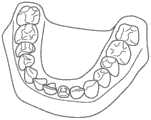
图2示出了从口内扫描图得到的牙齿和齿龈的3D模型;Figure 2 shows a 3D model of teeth and gums obtained from intraoral scans;
图3为利用3D扫描图跟踪牙龈线并且估计牙龈线变化的方法的流程图;Fig. 3 is a flow chart of a method for tracking gum line and estimating gum line changes using 3D scanning images;
图4为用于在3D扫描图上显示牙周测量结果的方法的流程图;Figure 4 is a flowchart of a method for displaying periodontal measurements on a 3D scan;
图5为示出3D扫描图上的牙周测量结果的图像;FIG. 5 is an image showing periodontal measurements on a 3D scan;
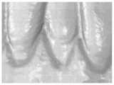
图6和图7为示出作为改变图像之间的位置的效果的牙龈线变化或退缩的图像;Figures 6 and 7 are images showing a change or recession of the gum line as an effect of changing the position between the images;
图8为示出被显示为叠加在3D扫描图上的两条线的牙龈线变化或退缩的图像;并且FIG. 8 is an image showing a change or recession of the gum line displayed as two lines superimposed on the 3D scan; and
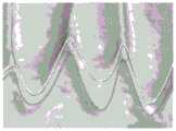
图9为示出被显示为位于两次牙龈线分割之间的区域的牙龈线变化或退缩的图像。FIG. 9 is an image showing a change or recession of the gum line in an area displayed as being between two gum line divisions.
具体实施方式Detailed ways
使用数字3D模型在牙科市场变得越来越流行。这些模型可以在活体内通过口内扫描仪获得,或通过传统印模的激光扫描离线获得。数字3D模型可用于各种临床任务(包括诊断辅助中的治疗规划),例如以跟踪牙龈线变化。The use of digital 3D models is becoming more and more popular in the dental market. These models can be obtained in vivo with an intraoral scanner, or offline with laser scanning of traditional impressions. Digital 3D models can be used for various clinical tasks (including treatment planning in diagnostic assistance), for example to track gum line changes.
图1为利用基于口内3D扫描图的数字3D模型来跟踪牙龈线并且估计牙龈线变化的系统10的图示。系统10包括处理器20,该处理器接收牙齿(12)的来自口内3D牙齿扫描图或牙齿印模扫描图的数字3D模型。系统10还可包括电子显示装置16(诸如液晶显示器(LCD)装置)以及用于接收用户命令或其他信息的输入装置18。从扫描图得到的患者牙齿和齿龈的数字3D模型的示例示于图2中。在美国专利7,956,862和7,605,817中公开了基于来自多个视图的图像集来生成数字3D图像或模型的系统,这两个专利都如同全文陈述一样以引用方式并入本文。这些系统可利用口内扫描仪来从牙齿或其他口内结构的多个视图中获得数字图像,并且处理这些数字图像,以生成表示扫描的牙齿和齿龈的数字3D模型。系统10可以用例如台式电脑、笔记本电脑或平板电脑来实现。系统10可通过网络从本地或从远程接收3D扫描图。FIG. 1 is an illustration of a
本文所介绍的3D扫描图用三角形网格表示。三角形网格是3D表面的常见表示方式,并且具有两个分量。第一分量称作网格的顶点,其仅仅是表面(即,点云)上已重新构建的3D点的坐标。第二分量(即网格面)对物体上的点之间的关联进行编码,并且是一种在连续表面上的离散样品点之间进行插值的有效方式。每个面是由三个顶点限定的三角形,从而得到可以由一组小三角形平面贴片表示的表面。The 3D scans presented in this article are represented by triangular meshes. Triangular meshes are a common representation of 3D surfaces and have two components. The first component is called the vertices of the mesh, which are simply the coordinates of the reconstructed 3D points on the surface (ie point cloud). The second component, the mesh surface, encodes the relationship between points on the object and is an efficient way to interpolate between discrete sample points on a continuous surface. Each face is a triangle bounded by three vertices, resulting in a surface that can be represented by a set of small triangular planar patches.
图3为利用3D扫描图跟踪牙龈线并且估计牙龈线变化的方法的流程图。图3的流程图中的方法可在软件或固件模块中实现,例如用于由处理器20执行,或者另选地可在硬件模块或者软件和硬件的组合中实现。该方法包括接收患者的牙齿和齿龈的第一3D扫描图(3D扫描图1),任选地对齐并取向3D扫描图1(步骤22),以及在3D扫描图1中分割牙齿与齿龈,以确定牙龈线(步骤26)。该方法还包括接收同一患者的牙齿和齿龈的第二3D扫描图(3D扫描图2),任选地对齐并取向3D扫描图2(步骤24),以及在3D扫描图2中分割牙齿与齿龈,以确定牙龈线(步骤28)。在该方法中,3D扫描图2在不同于3D扫描图1的时间(通常在稍晚时间)获得。来自不同时间的仅两个3D扫描图被列出,以用于例示性目的。该方法可用于处理在特定时间段内的不同时间获得的多个3D扫描图。例如,每当患者到牙科诊所就诊时,就可扫描患者的牙齿和齿龈,并且可通过该方法处理随时间变化的这些3D扫描图。该方法也可用于比较不同患者之间或单个患者之间的3D扫描图与一个或多个典型的牙齿和齿龈的患者模型。FIG. 3 is a flowchart of a method for tracking gum line and estimating changes in gum line using a 3D scan. The method in the flowchart of Fig. 3 may be implemented in a software or firmware module, eg for execution by the
该方法通过配准分割齿龈的3D扫描图1与分割齿龈的3D扫描图2来处理3D扫描图(步骤30)。使用分割齿龈的3D扫描图的该配准来比较牙龈线(步骤32)并且产生牙龈线变化标测图(步骤34)。取代使用配准算法,可通过其他方式比较3D扫描图。The method processes the 3D scan image by registering the
取代或除了比较人牙齿和齿龈的扫描图,该方法还可预测牙龈线变化。基于扫描图的数据库,来预测原始牙龈线位置(步骤36)。为了实现这一点,可访问和使用3D牙齿和齿龈模型的大数据库,其中数据库内的每个扫描图中的牙龈线位置为已知的。可基于相应患者的特性,来选择得自数据库的模型。鉴于此数据库,可由规范化原始牙龈线位置形成总体通用数学模型。鉴于此数据库和从其获得的数学模型,可预测当前扫描图中的原始牙龈线位置。存在若干用于执行此步骤的方法。一种方法如下所示。首先,确定得自数据库的用于当前扫描图的适当模型。然后,计算从模型牙齿和齿龈到当前牙齿和齿龈的映射。可通过使用配准算法来实现这种映射(步骤38)。使用这种映射,将模型牙龈线映射到当前牙齿和齿龈的空间,从而得到牙龈线的原始位置的预测。Instead of, or in addition to, comparing scans of a person's teeth and gums, the method can also predict changes in the gum line. Based on the database of scans, the original gum line position is predicted (step 36). To achieve this, a large database of 3D tooth and gum models, where the position of the gum line is known in each scan within the database, can be accessed and used. A model from the database can be selected based on the characteristics of the corresponding patient. Given this database, an overall general mathematical model can be formed from the normalized raw gum line position. Given this database and the mathematical model derived therefrom, the original gum line position in the current scan can be predicted. There are several methods for performing this step. One method is shown below. First, an appropriate model for the current scan is determined from the database. Then, calculate the mapping from the model teeth and gums to the current teeth and gums. This mapping can be achieved by using a registration algorithm (step 38). Using this mapping, the model gum line is mapped to the current tooth and gum space, resulting in a prediction of the original position of the gum line.
一旦原始牙龈线位置已被估计,就可将其与实际牙龈线位置进行比较,以便评估牙龈线变化量。然后,必须定位并且比较其中实际模型与预测模型不一致的区域(步骤40)。该比较基于例如原始的预测牙龈线位置与当前的牙龈线位置的间隔度或间隔量,来实现牙龈线变化的估计(步骤42)。可显示具有估计的牙龈线变化的结果的牙龈线变化标测图(步骤44)。Once the original gum line position has been estimated, it can be compared to the actual gum line position in order to assess the amount of gum line change. Then, regions where the actual model does not agree with the predicted model must be located and compared (step 40). This comparison enables estimation of the gum line change based on, for example, the degree or amount of separation between the original predicted gum line position and the current gum line position (step 42 ). A gum line change map may be displayed with the results of the estimated gum line change (step 44).
用于步骤22和步骤24的任选对齐和取向涉及旋转和平移3D扫描图,以使它们与特定坐标系对齐。例如,在3D坐标系中,3D扫描图可与XZ平面基本上平行对齐,其中牙齿沿Y轴向上指向。3D扫描图可以其他方式进行对齐。对齐和取向3D扫描图可有利于多个扫描图的进一步处理,例如3D扫描图的分割和配准。用于对齐和取向3D扫描图的方法的示例在美国专利申请公布2016/0070821中有所公开,该专利申请公布如同全文陈述一样以引用方式并入本文。在一些情况下,可提供软件界面,以便使用户手动地执行对齐或其一部分。The optional alignment and orientation for
步骤26和步骤28中的分割牙齿与齿龈涉及检测3D扫描图中的牙龈线,以数字地识别牙齿与齿龈之间的边界,由此生成分割齿龈的数字3D模型。用于分割的这种数字识别可包括例如数字地分开牙齿与齿龈,或者利用数字3D模型上的曲线或其他标记来区分牙齿与牙龈。Segmenting the teeth and gums in
表1提供了用于针对步骤26和步骤28的分割来检测牙龈线的示例性伪码。Table 1 provides exemplary pseudocode for detecting the gum line for the segmentation of

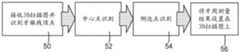
图4为用于在3D扫描图(诸如在图3的流程图中引用的扫描图1和扫描图2)上显示牙周测量结果的方法的流程图。如图4所示,该方法接收一个或多个3D扫描图并且通过提取牙齿与齿龈的分割边界来查找牙龈线顶点(步骤50)。随后可使用若干方法中的一种来识别中心点(步骤52)。第一选择为识别牙龈线顶点列表中的中间顶点。第二选择为沿着利用主成分分析导出的主轴重新对齐顶点,然后通过查找斜率改变符号的点(即,零值导数)来查找曲线的峰值。第三选择为使用有关分割牙齿本身的解剖信息来查找中点。此类信息可包括牙齿的上下轴,或对于尖牙、双尖牙或磨牙而言的尖端的位置。4 is a flowchart of a method for displaying periodontal measurements on a 3D scan map, such as
该方法识别侧边点(步骤54),并且侧边点识别也可以若干方式中的一种来进行。一种选择是识别最靠近每个牙齿与其相邻牙齿之间的边界的点。另一种选择为识别沿牙龈线点位于与中心相距给定距离d处的点。另选地,可将侧边点识别为与主成分分析(PCA)取向顶点相距给定高度h的点。如同中心点,有关分割牙齿的解剖信息也可用于查找侧边点。The method identifies side points (step 54), and side point identification can also be done in one of several ways. One option is to identify the point closest to the boundary between each tooth and its neighbors. Another option is to identify points along the gum line at a given distance d from the center. Alternatively, side points may be identified as points at a given height h from a principal component analysis (PCA) oriented vertex. As with the center point, anatomical information about the segmented tooth can also be used to find the side points.
该方法还包括将牙周测量结果设置在一个或多个3D扫描图上或附近(步骤56)。可将牙周测量结果的标识符直接设置在中心-侧边点位置处或设置在偏离这些位置的位置处。还可显示得自先前就诊的牙周测量结果,以指示就诊之间的牙齿状况的变化。图5为示出设置在3D扫描图或数字3D模型上的牙周测量结果的图像。牙周测量结果的设置可包括但不限于以下步骤:将测量结果覆盖或叠加在扫描图上;在扫描图的并排视图中显示测量结果;以及利用悬停文本在扫描图上显示测量结果。The method also includes positioning the periodontal measurements on or adjacent to the one or more 3D scans (step 56). Identifiers for periodontal measurements can be placed directly at the center-lateral point positions or at positions offset from these positions. Periodontal measurements from previous visits may also be displayed to indicate changes in dental condition between visits. FIG. 5 is an image showing periodontal measurement results placed on a 3D scan or a digital 3D model. Setting up periodontal measurements may include, but is not limited to, the steps of: overlaying or overlaying the measurements on the scan; displaying the measurements in a side-by-side view of the scan; and displaying the measurements on the scan with hover text.
用于步骤30和步骤38的配准涉及通过在两个不同的时间扫描牙齿来获得牙齿和齿龈的分割的数字3D模型,以及旋转并平移这些模型,以将它们共同对齐,由此用于检测这两个模型中的变化。具体地,配准为对齐或获得最佳拟合旋转和平移的过程,该最佳拟合旋转和平移需要被应用到移动网格,以与固定网格对齐或者被推广到多个网格。Registration for
在示例性实施方案中,配准可利用迭代最近点(ICP)算法来实现表示数字3D模型的网格之间的配准。ICP算法的一种变型包括表2中的步骤。对于该示例性实施方案,配准(参考表2中的步骤)在步骤1中使用全部点,在步骤2中使用欧氏点到平面距离,使用对的等权重并且基于固定的预定阈值拒绝对(步骤3和步骤4),在步骤5中使用平方距离的和作为度量,并且在步骤6中利用奇异值分解(SVD)和列文伯格-麦夸特(levenberg marquart)方法来实现最小化。In an exemplary embodiment, registration may utilize an iterative closest point (ICP) algorithm to achieve registration between meshes representing the digital 3D model. A variant of the ICP algorithm includes the steps in Table 2. For this exemplary embodiment, the registration (see steps in Table 2) uses all points in
任选地,一旦达到最终配准最佳状态,就可验证这种状态是否确实为稳定的最佳状态。这可通过两种可能的方式来进行:第一,通过少量的旋转和平移来扰动最佳状态,以确定其是否收敛回到原始最佳状态,或者是否可达到更好的最佳状态;第二,通过利用不同量的初始旋转和平移来执行ICP算法的随机重新启动,以确定对于每个初值是否达到这些状态中的最佳状态。Optionally, once the final registration optimal state is reached, it can be verified that this state is indeed a stable optimal state. This can be done in two possible ways: first, perturb the optimal state by a small amount of rotation and translation to see if it converges back to the original optimal state, or if a better optimal state can be reached; second Two, perform random restarts of the ICP algorithm by using different amounts of initial rotation and translation to determine if the best of these states is reached for each initial value.


步骤30和步骤38中的配准提供了配准的3D扫描图之间的牙龈线变化的指示,以用于在步骤32和步骤40中比较牙龈线。牙龈线比较可用于生成步骤34的牙龈线变化标测图和步骤44的估计的牙龈线变化标测图,以示出牙龈线变化,该牙龈线变化可被显示为如图6和图7所示的改变网格之间的位置的效果(例如,阴影或线)、或如图8所示的叠加在单一网格上的两条线。首先应用变换矩阵,以使前一扫描图中的牙齿边界与当前扫描图相关联。随后可在当前扫描图上的牙齿边界的位置处插入诸如颜色或阴影之类的效果。任选地,也可在应用变换之前或之后执行牙龈线平滑。The registration in
从图8所示的输出中,也可通过测量两个分割结果中的对应点之间的距离来实现定量牙龈线变化(诸如牙龈线退缩)测量。对应点可利用若干选择中的一个来识别,包括点之间的最小距离(欧氏距离或沿网格的路径长度)、点之间的沿固定方向的距离、或点之间的沿由分割结果中的一个上的切线的法线限定的方向的距离。From the output shown in Figure 8, quantitative gum line change (such as gum line recession) measurement can also be achieved by measuring the distance between corresponding points in the two segmented results. Corresponding points can be identified using one of several options, including a minimum distance between points (Euclidean distance or path length along a grid), a distance between points along a fixed direction, or an edge between points separated by The result is a distance in a direction defined by the normal to the tangent.
对应牙龈线点识别还可有利于绘制在第一扫描图与第二扫描图之间产生的渐进变化。这些渐进变化可显示为表示随时间变化的牙龈线变化的一系列图像或视频。首先,执行对应点之间的线性或非线性内插。然后识别每个内插点在网格上的最近点。随后通过连接内插点并任选地执行平滑来形成新的渐进时间点牙龈线绘制。也可应用线性或非线性外插来实现将来可发生的变化的绘制。Corresponding gum line point identification may also facilitate mapping the gradual change that occurs between the first scan and the second scan. These gradual changes can be displayed as a series of images or videos showing changes in the gum line over time. First, a linear or non-linear interpolation between corresponding points is performed. The closest point on the grid is then identified for each interpolated point. A new progressive time point gum line rendering is then formed by connecting the interpolated points and optionally performing smoothing. Linear or non-linear extrapolation may also be applied to enable mapping of changes that may occur in the future.
定量退缩测量结果可用于有利于实现区域中的显著效果(例如,较明显阴影),以显示较极端变化。例如,可根据所测量的牙龈线退缩测量结果的量值来缩放阴影效果的尺寸和暗度。这种可视化技术并不限于牙龈线退缩显示。相反,显著的阴影或对比度效果通常可用于视觉地传递扫描图之间的定量测量变化。Quantitative shrinkage measurements can be used to favor dramatic effects (eg, more pronounced shading) in regions to show more extreme changes. For example, the size and darkness of the shadow effect may be scaled according to the magnitude of the measured gum line recession measurements. This visualization technique is not limited to gum line recession display. Instead, dramatic shading or contrast effects are often used to visually communicate quantitative measurement changes between scans.
牙龈线变化或退缩也可被表示为如图9所示的两个牙龈线分割结果之间的区域。将变换应用于前一扫描图中的全部网格,以使其与当前扫描图相关联。前一扫描图中的每个点在当前扫描图中的最近点被分配前一扫描图中给出的标签。例如以特定颜色显示的表现出退缩的点被识别为在前一扫描图中分配牙龈标签的点和在当前扫描图中分配牙齿标签的点。The gum line change or recession can also be expressed as the area between two gum line segmentation results as shown in FIG. 9 . Applies a transformation to all meshes in the previous scan to make them relative to the current scan. The closest point in the current scan to each point in the previous scan is assigned the label given in the previous scan. Points exhibiting retraction, eg shown in a particular color, are identified as points assigned a gingival label in the previous scan and points assigned a dental label in the current scan.
也可将另外图5中所示的牙周测量结果设置在牙龈线变化标测图上,诸如图6-图9所示的标测图。The additional periodontal measurements shown in FIG. 5 may also be placed on a gum line change map, such as the maps shown in FIGS. 6-9 .
Claims (10)
Translated fromChineseApplications Claiming Priority (3)
| Application Number | Priority Date | Filing Date | Title |
|---|---|---|---|
| US15/643,646US10327693B2 (en) | 2017-07-07 | 2017-07-07 | Tools for tracking the gum line and displaying periodontal measurements using intra-oral 3D scans |
| US15/643,646 | 2017-07-07 | ||
| PCT/IB2018/054713WO2019008468A1 (en) | 2017-07-07 | 2018-06-26 | Tools for tracking the gum line and displaying periodontal measurements using intra-oral 3d scans |
Publications (2)
| Publication Number | Publication Date |
|---|---|
| CN110868913A CN110868913A (en) | 2020-03-06 |
| CN110868913Btrue CN110868913B (en) | 2023-02-10 |
Family
ID=64904316
Family Applications (1)
| Application Number | Title | Priority Date | Filing Date |
|---|---|---|---|
| CN201880045456.6AActiveCN110868913B (en) | 2017-07-07 | 2018-06-26 | Tool to track gum line and display periodontal measurements using 3D scans of the mouth |
Country Status (6)
| Country | Link |
|---|---|
| US (2) | US10327693B2 (en) |
| EP (1) | EP3648660A4 (en) |
| JP (1) | JP2020526302A (en) |
| CN (1) | CN110868913B (en) |
| AU (1) | AU2018295521B2 (en) |
| WO (1) | WO2019008468A1 (en) |
Families Citing this family (9)
| Publication number | Priority date | Publication date | Assignee | Title |
|---|---|---|---|---|
| FR3092427B1 (en)* | 2019-02-04 | 2022-07-08 | Borea | automatic tooth segmentation method |
| EP3709305A1 (en)* | 2019-03-11 | 2020-09-16 | 3Shape A/S | Method for graphically presenting a plurality of scans |
| CN111260672B (en)* | 2019-12-26 | 2023-09-05 | 北京大学口腔医学院 | Method for guiding and segmenting teeth by using morphological data |
| US10751149B1 (en) | 2020-02-18 | 2020-08-25 | Oxilio Ltd | Method of determining deformation of gingiva |
| WO2021202347A1 (en)* | 2020-04-01 | 2021-10-07 | Easyrx Llc. | System and method for removing brackets from customized orthodontic appliances and products |
| CN113538437B (en)* | 2020-04-21 | 2025-02-18 | 杭州朝厚信息科技有限公司 | A method for detecting segmentation results of three-dimensional digital models of teeth and jaws |
| US12370016B2 (en)* | 2020-09-11 | 2025-07-29 | Align Technology, Inc. | Automatic segmentation quality assessment for secondary treatment plans |
| US20220262007A1 (en)* | 2021-02-12 | 2022-08-18 | Align Technology, Inc. | Machine learning dental segmentation system and methods using graph-based approaches |
| CN112700447B (en)* | 2021-03-24 | 2021-06-18 | 南京佳和牙科技术有限公司 | Automatic gum line extraction method based on digital tooth model |
Citations (11)
| Publication number | Priority date | Publication date | Assignee | Title |
|---|---|---|---|---|
| US6514074B1 (en)* | 1999-05-14 | 2003-02-04 | Align Technology, Inc. | Digitally modeling the deformation of gingival |
| JP2005199084A (en)* | 2005-03-01 | 2005-07-28 | Align Technology Inc | System and method of removing gingiva from tooth |
| CN101536000A (en)* | 2006-07-06 | 2009-09-16 | 史密丝克莱恩比彻姆公司 | System and method for manufacturing full and partial dentures |
| CN101940503A (en)* | 2005-11-30 | 2011-01-12 | 3形状股份有限公司 | Impression scanning for manufacturing of dental restorations |
| CN102858266A (en)* | 2010-04-20 | 2013-01-02 | 登塔尔图像科技公司 | Reduction and removal of artifacts from a three-dimensional dental X-ray data set using surface scan information |
| CN103445877A (en)* | 2012-06-01 | 2013-12-18 | 索尼公司 | Dental apparatus, medical apparatus and calculation method |
| CN104780822A (en)* | 2012-07-19 | 2015-07-15 | 独立行政法人国立长寿医疗研究中心 | Measurement/display method and measurement/display device for dental plaque, gum and alveolar bone |
| CN105919684A (en)* | 2016-05-27 | 2016-09-07 | 穆檬檬 | Method for building three-dimensional tooth-and-jaw fusion model |
| CN106037979A (en)* | 2016-05-16 | 2016-10-26 | 杭州美齐科技有限公司 | Digital gum line extracting method |
| CN106228549A (en)* | 2016-07-14 | 2016-12-14 | 嘉兴学院 | A kind of triangle gridding tooth dividing method based on path planning |
| CN106572831A (en)* | 2014-05-07 | 2017-04-19 | 阿莱恩技术有限公司 | Identification of regions of interest during intraoral scans |
Family Cites Families (32)
| Publication number | Priority date | Publication date | Assignee | Title |
|---|---|---|---|---|
| US6201880B1 (en)* | 1996-12-31 | 2001-03-13 | Electro-Optical Sciences | Method and apparatus for electronically imaging a tooth through transillumination by light |
| US7160110B2 (en) | 1999-11-30 | 2007-01-09 | Orametrix, Inc. | Three-dimensional occlusal and interproximal contact detection and display using virtual tooth models |
| US7471821B2 (en) | 2000-04-28 | 2008-12-30 | Orametrix, Inc. | Method and apparatus for registering a known digital object to scanned 3-D model |
| US7040896B2 (en) | 2000-08-16 | 2006-05-09 | Align Technology, Inc. | Systems and methods for removing gingiva from computer tooth models |
| DE10129694C1 (en)* | 2001-06-22 | 2003-02-06 | Sirona Dental Systems Gmbh | Method and device for recognizing pathological changes such as caries, plaque, concretions or bacterial infection on a tissue surface, in particular on teeth |
| US7077647B2 (en) | 2002-08-22 | 2006-07-18 | Align Technology, Inc. | Systems and methods for treatment analysis by teeth matching |
| US7156661B2 (en)* | 2002-08-22 | 2007-01-02 | Align Technology, Inc. | Systems and methods for treatment analysis by teeth matching |
| US7695278B2 (en) | 2005-05-20 | 2010-04-13 | Orametrix, Inc. | Method and system for finding tooth features on a virtual three-dimensional model |
| US8126726B2 (en)* | 2004-02-27 | 2012-02-28 | Align Technology, Inc. | System and method for facilitating automated dental measurements and diagnostics |
| US7324661B2 (en)* | 2004-04-30 | 2008-01-29 | Colgate-Palmolive Company | Computer-implemented system and method for automated and highly accurate plaque analysis, reporting, and visualization |
| US7605817B2 (en) | 2005-11-09 | 2009-10-20 | 3M Innovative Properties Company | Determining camera motion |
| DE102007012584A1 (en)* | 2007-03-13 | 2008-09-18 | Paul Weigl | Method for controlling preparation of a prepared tooth by CAD method |
| US8275180B2 (en) | 2007-08-02 | 2012-09-25 | Align Technology, Inc. | Mapping abnormal dental references |
| US8075306B2 (en) | 2007-06-08 | 2011-12-13 | Align Technology, Inc. | System and method for detecting deviations during the course of an orthodontic treatment to gradually reposition teeth |
| US7942672B2 (en)* | 2008-02-15 | 2011-05-17 | Align Technology, Inc. | Gingiva modeling |
| US8199988B2 (en)* | 2008-05-16 | 2012-06-12 | Geodigm Corporation | Method and apparatus for combining 3D dental scans with other 3D data sets |
| CN100581461C (en)* | 2008-05-23 | 2010-01-20 | 宁波思达利光电科技有限公司 | Device for measuring tooth geometry |
| US8244028B2 (en) | 2010-04-30 | 2012-08-14 | Align Technology, Inc. | Virtual cephalometric imaging |
| US9211166B2 (en)* | 2010-04-30 | 2015-12-15 | Align Technology, Inc. | Individualized orthodontic treatment index |
| EP2452652A1 (en)* | 2010-11-10 | 2012-05-16 | Straumann Holding AG | Non-invasive method for semi-automatic detection and measurement of periodontal bone defects |
| DE102012201193B3 (en)* | 2012-01-27 | 2013-06-13 | Sirona Dental Systems Gmbh | Method and reference model for checking a surveying system |
| US9855114B2 (en)* | 2013-05-21 | 2018-01-02 | Carestream Health, Inc. | Method and system for user interaction in 3-D cephalometric analysis |
| US11122180B2 (en)* | 2014-05-02 | 2021-09-14 | Dentsply Sirona Inc. | Systems, methods, apparatuses, and computer-readable storage media for collecting color information about an object undergoing a 3D scan |
| US9626462B2 (en)* | 2014-07-01 | 2017-04-18 | 3M Innovative Properties Company | Detecting tooth wear using intra-oral 3D scans |
| US10192003B2 (en)* | 2014-09-08 | 2019-01-29 | 3M Innovative Properties Company | Method of aligning intra-oral digital 3D models |
| US11147652B2 (en)* | 2014-11-13 | 2021-10-19 | Align Technology, Inc. | Method for tracking, predicting, and proactively correcting malocclusion and related issues |
| US9737257B2 (en) | 2015-01-30 | 2017-08-22 | 3M Innovative Properties Company | Estimating and predicting tooth wear using intra-oral 3D scans |
| US9770217B2 (en)* | 2015-01-30 | 2017-09-26 | Dental Imaging Technologies Corporation | Dental variation tracking and prediction |
| US10032271B2 (en) | 2015-12-10 | 2018-07-24 | 3M Innovative Properties Company | Method for automatic tooth type recognition from 3D scans |
| US10842594B2 (en)* | 2016-05-24 | 2020-11-24 | Clearcorrect Operating, Llc | Virtual modeling of gingiva adaptations to progressive orthodontic correction and associated methodology of appliance manufacture |
| CN106204739A (en)* | 2016-07-19 | 2016-12-07 | 上海爱圣美科技有限公司 | A kind of method that in three-dimensional tooth model, gingiva is rebuild |
| US10499793B2 (en)* | 2017-02-17 | 2019-12-10 | Align Technology, Inc. | Longitudinal analysis and visualization under limited accuracy system |
- 2017
- 2017-07-07USUS15/643,646patent/US10327693B2/enactiveActive
- 2018
- 2018-06-26CNCN201880045456.6Apatent/CN110868913B/enactiveActive
- 2018-06-26JPJP2020500164Apatent/JP2020526302A/enactivePending
- 2018-06-26AUAU2018295521Apatent/AU2018295521B2/ennot_activeCeased
- 2018-06-26EPEP18827866.7Apatent/EP3648660A4/enactivePending
- 2018-06-26WOPCT/IB2018/054713patent/WO2019008468A1/ennot_activeCeased
- 2019
- 2019-05-07USUS16/405,215patent/US10758171B2/enactiveActive
Patent Citations (11)
| Publication number | Priority date | Publication date | Assignee | Title |
|---|---|---|---|---|
| US6514074B1 (en)* | 1999-05-14 | 2003-02-04 | Align Technology, Inc. | Digitally modeling the deformation of gingival |
| JP2005199084A (en)* | 2005-03-01 | 2005-07-28 | Align Technology Inc | System and method of removing gingiva from tooth |
| CN101940503A (en)* | 2005-11-30 | 2011-01-12 | 3形状股份有限公司 | Impression scanning for manufacturing of dental restorations |
| CN101536000A (en)* | 2006-07-06 | 2009-09-16 | 史密丝克莱恩比彻姆公司 | System and method for manufacturing full and partial dentures |
| CN102858266A (en)* | 2010-04-20 | 2013-01-02 | 登塔尔图像科技公司 | Reduction and removal of artifacts from a three-dimensional dental X-ray data set using surface scan information |
| CN103445877A (en)* | 2012-06-01 | 2013-12-18 | 索尼公司 | Dental apparatus, medical apparatus and calculation method |
| CN104780822A (en)* | 2012-07-19 | 2015-07-15 | 独立行政法人国立长寿医疗研究中心 | Measurement/display method and measurement/display device for dental plaque, gum and alveolar bone |
| CN106572831A (en)* | 2014-05-07 | 2017-04-19 | 阿莱恩技术有限公司 | Identification of regions of interest during intraoral scans |
| CN106037979A (en)* | 2016-05-16 | 2016-10-26 | 杭州美齐科技有限公司 | Digital gum line extracting method |
| CN105919684A (en)* | 2016-05-27 | 2016-09-07 | 穆檬檬 | Method for building three-dimensional tooth-and-jaw fusion model |
| CN106228549A (en)* | 2016-07-14 | 2016-12-14 | 嘉兴学院 | A kind of triangle gridding tooth dividing method based on path planning |
Non-Patent Citations (1)
| Title |
|---|
| 计算机辅助牙齿隐形正畸系统;范然等;《计算机辅助设计与图形学学报》;20130115(第01期);83-92* |
Also Published As
| Publication number | Publication date |
|---|---|
| EP3648660A1 (en) | 2020-05-13 |
| AU2018295521A1 (en) | 2020-01-30 |
| CN110868913A (en) | 2020-03-06 |
| US10327693B2 (en) | 2019-06-25 |
| US20190008446A1 (en) | 2019-01-10 |
| AU2018295521B2 (en) | 2021-06-10 |
| WO2019008468A1 (en) | 2019-01-10 |
| EP3648660A4 (en) | 2021-04-28 |
| US10758171B2 (en) | 2020-09-01 |
| US20190254588A1 (en) | 2019-08-22 |
| JP2020526302A (en) | 2020-08-31 |
Similar Documents
| Publication | Publication Date | Title |
|---|---|---|
| CN110868913B (en) | Tool to track gum line and display periodontal measurements using 3D scans of the mouth | |
| US10410346B2 (en) | Detecting tooth wear using intra-oral 3D scans | |
| JP7245809B2 (en) | How to align an intraoral digital 3D model | |
| US11058514B2 (en) | Method and system for dentition mesh braces removal | |
| US9737257B2 (en) | Estimating and predicting tooth wear using intra-oral 3D scans | |
| CN116868232A (en) | Apparatus and method for automatically matching oral scan data and computed tomography images by coronal portion segmentation of oral scan data | |
| JP2022549281A (en) | Method, system and computer readable storage medium for registering intraoral measurements | |
| JP2019536561A (en) | Method and system for brace removal from dentition mesh | |
| EP3709305A1 (en) | Method for graphically presenting a plurality of scans | |
| WO2016143022A1 (en) | Crown information acquisition program, information processing device, and crown information acquisition method | |
| Xie et al. | Tooth Motion Monitoring in Orthodontic Treatment by Mobile Device-based Multi-view Stereo | |
| EP4393449A1 (en) | Method and system for tooth wear detection | |
| Ahn et al. | Automatic subtraction radiography algorithm for detection of periodontal disease in internet environment | |
| Catherwood et al. | 3D stereophotogrammetry: post-processing and surface integration | |
| Ahn et al. | Marginal bone destructions in dental radiography using multi-template based on internet services |
Legal Events
| Date | Code | Title | Description |
|---|---|---|---|
| PB01 | Publication | ||
| PB01 | Publication | ||
| SE01 | Entry into force of request for substantive examination | ||
| SE01 | Entry into force of request for substantive examination | ||
| GR01 | Patent grant | ||
| GR01 | Patent grant | ||
| TR01 | Transfer of patent right | ||
| TR01 | Transfer of patent right | Effective date of registration:20240408 Address after:U.S.A. Patentee after:Shuwanuo Intellectual Property Co. Country or region after:U.S.A. Address before:American Minnesota Patentee before:3M INNOVATIVE PROPERTIES Co. Country or region before:U.S.A. |