CN110861576B - Control method and device of brake lamp - Google Patents
Control method and device of brake lampDownload PDFInfo
- Publication number
- CN110861576B CN110861576BCN201911337883.4ACN201911337883ACN110861576BCN 110861576 BCN110861576 BCN 110861576BCN 201911337883 ACN201911337883 ACN 201911337883ACN 110861576 BCN110861576 BCN 110861576B
- Authority
- CN
- China
- Prior art keywords
- vehicle
- mcu
- vcu
- disconnected
- detected
- Prior art date
- Legal status (The legal status is an assumption and is not a legal conclusion. Google has not performed a legal analysis and makes no representation as to the accuracy of the status listed.)
- Active
Links
Images


Classifications
- B—PERFORMING OPERATIONS; TRANSPORTING
- B60—VEHICLES IN GENERAL
- B60Q—ARRANGEMENT OF SIGNALLING OR LIGHTING DEVICES, THE MOUNTING OR SUPPORTING THEREOF OR CIRCUITS THEREFOR, FOR VEHICLES IN GENERAL
- B60Q1/00—Arrangement of optical signalling or lighting devices, the mounting or supporting thereof or circuits therefor
- B60Q1/26—Arrangement of optical signalling or lighting devices, the mounting or supporting thereof or circuits therefor the devices being primarily intended to indicate the vehicle, or parts thereof, or to give signals, to other traffic
- B60Q1/44—Arrangement of optical signalling or lighting devices, the mounting or supporting thereof or circuits therefor the devices being primarily intended to indicate the vehicle, or parts thereof, or to give signals, to other traffic for indicating braking action or preparation for braking, e.g. by detection of the foot approaching the brake pedal
Landscapes
- Engineering & Computer Science (AREA)
- Mechanical Engineering (AREA)
- Lighting Device Outwards From Vehicle And Optical Signal (AREA)
Abstract
Description
Translated fromChinese技术领域technical field
本公开涉及车辆技术领域,特别涉及一种刹车灯的控制方法及装置。The present disclosure relates to the technical field of vehicles, and in particular, to a control method and device for a brake light.
背景技术Background technique
刹车灯是车辆预防事故发生的重要信号装置之一。Brake lights are one of the important signaling devices for vehicles to prevent accidents.
相关技术中,当驾驶员踩下车辆中的制动踏板时,车辆会接收到制动信号,此时,车辆可以控制其内部的刹车灯点亮;当驾驶员未踩下车辆中的制动踏板时,车辆不会接收到制动信号,此时,车辆可以控制其内部的刹车灯熄灭。In the related art, when the driver depresses the brake pedal in the vehicle, the vehicle will receive a braking signal, and at this time, the vehicle can control its internal brake lights to light up; when the driver does not depress the brake pedal in the vehicle When the pedal is pressed, the vehicle will not receive a braking signal, and at this time, the vehicle can control its internal brake lights to go out.
然而,目前大部分车辆中的刹车灯仅在驾驶员踩下制动板时被点亮,刹车灯的功能较为单一。However, at present, the brake lights in most vehicles are only illuminated when the driver depresses the brake pedal, and the function of the brake lights is relatively simple.
发明内容SUMMARY OF THE INVENTION
本公开实施例提供了一种刹车灯的控制方法及装置。可以解决现有技术中刹车灯的功能较为单一的问题,所述技术方案如下:Embodiments of the present disclosure provide a control method and device for a brake light. The problem that the function of the brake light in the prior art is relatively single can be solved, and the technical solution is as follows:
一方面,提供了一种刹车灯的控制方法方法,所述方法包括:In one aspect, a method for controlling a brake light is provided, the method comprising:
在车辆正常行驶时,检测车辆是否接收到制动信号;When the vehicle is running normally, detect whether the vehicle receives a braking signal;
若检测到车辆未接收到制动信号,当检测到所述车辆中的驱动电机的转速降低时,控制所述车辆中的刹车灯点亮。If it is detected that the vehicle does not receive a braking signal, when it is detected that the rotational speed of the driving motor in the vehicle decreases, the brake light in the vehicle is controlled to be turned on.
可选的,当检测到所述车辆中的驱动电机的转速降低时,控制所述车辆中的刹车灯点亮之前,所述方法还包括:Optionally, when it is detected that the rotational speed of the driving motor in the vehicle decreases, before controlling the braking light in the vehicle to light up, the method further includes:
检测所述车辆中的电机控制器MCU的高压电源端与所述车辆中的电池包之间的电连接是否断开;Detecting whether the electrical connection between the high-voltage power supply terminal of the motor controller MCU in the vehicle and the battery pack in the vehicle is disconnected;
若检测到所述车辆中的MCU与所述车辆中的电池包之间的连接断开,确定所述车辆中的驱动电机的转速降低。If it is detected that the connection between the MCU in the vehicle and the battery pack in the vehicle is disconnected, it is determined that the rotational speed of the drive motor in the vehicle is reduced.
可选的,当检测到所述车辆中的驱动电机的转速降低时,控制所述车辆中的刹车灯点亮之前,所述方法还包括:Optionally, when it is detected that the rotational speed of the driving motor in the vehicle decreases, before controlling the braking light in the vehicle to light up, the method further includes:
检测所述VCU与所述车辆中的MCU之间的通信连接是否断开;Detecting whether the communication connection between the VCU and the MCU in the vehicle is disconnected;
若检测到所述VCU与所述车辆中的MCU之间的通信连接断开,确定所述车辆中的驱动电机的转速降低。If it is detected that the communication connection between the VCU and the MCU in the vehicle is disconnected, it is determined that the rotational speed of the drive motor in the vehicle is reduced.
可选的,当检测到所述车辆中的驱动电机的转速降低时,控制所述车辆中的刹车灯点亮之前,所述方法还包括:Optionally, when it is detected that the rotational speed of the driving motor in the vehicle decreases, before controlling the braking light in the vehicle to light up, the method further includes:
检测所述车辆中的MCU与所述车辆中的驱动电机之间的通信连接是否断开;Detecting whether the communication connection between the MCU in the vehicle and the drive motor in the vehicle is disconnected;
若检测到所述车辆中的MCU与所述车辆中的驱动电机之间的通信连接断开,确定所述车辆中的驱动电机的转速降低。If it is detected that the communication connection between the MCU in the vehicle and the drive motor in the vehicle is disconnected, it is determined that the rotational speed of the drive motor in the vehicle is reduced.
可选的,当接收到危险警报灯启动信号时,控制所述刹车灯点亮。Optionally, when a hazard warning light activation signal is received, the brake light is controlled to be turned on.
另一方面,提供了一种刹车灯的控制装置,所述装置包括:In another aspect, a control device for a brake light is provided, the device comprising:
第一检测模块,用于在车辆正常行驶时,检测车辆是否接收到制动信号;a first detection module for detecting whether the vehicle receives a braking signal when the vehicle is running normally;
第一控制模块,用于若检测到车辆未接收到制动信号,当检测到所述车辆中的驱动电机的转速降低时,控制所述车辆中的刹车灯点亮。The first control module is configured to control a brake light in the vehicle to light up when it is detected that the vehicle does not receive a braking signal and when it is detected that the rotational speed of the driving motor in the vehicle decreases.
可选的,第二检测模块,用于检测所述车辆中的电机控制器MCU的高压电源端与所述车辆中的电池包之间的电连接是否断开;Optionally, a second detection module, configured to detect whether the electrical connection between the high-voltage power supply terminal of the motor controller MCU in the vehicle and the battery pack in the vehicle is disconnected;
第一确定模块,用于若检测到所述车辆中的MCU与所述车辆中的电池包之间的连接断开,确定所述车辆中的驱动电机的转速降低。The first determination module is configured to determine that the rotational speed of the drive motor in the vehicle is reduced if it is detected that the connection between the MCU in the vehicle and the battery pack in the vehicle is disconnected.
可选的,第三检测模块,用于检测所述VCU与所述车辆中的MCU之间的通信连接是否断开;Optionally, a third detection module, configured to detect whether the communication connection between the VCU and the MCU in the vehicle is disconnected;
第二确定模块,用于若检测到所述VCU与所述车辆中的MCU之间的通信连接断开,确定所述车辆中的驱动电机的转速降低。The second determination module is configured to determine that the rotational speed of the drive motor in the vehicle is reduced if it is detected that the communication connection between the VCU and the MCU in the vehicle is disconnected.
可选的,第四检测模块,用于检测所述车辆中的MCU与所述车辆中的驱动电机之间的通信连接是否断开;Optionally, a fourth detection module, configured to detect whether the communication connection between the MCU in the vehicle and the drive motor in the vehicle is disconnected;
第三确定模块,用于若检测到所述车辆中的MCU与所述车辆中的驱动电机之间的通信连接断开,确定所述车辆中的驱动电机的转速降低。The third determining module is configured to determine that the rotational speed of the driving motor in the vehicle decreases if it is detected that the communication connection between the MCU in the vehicle and the driving motor in the vehicle is disconnected.
可选的,第二控制模块,用于当接收到危险警报灯启动信号时,控制所述刹车灯点亮。Optionally, the second control module is configured to control the brake light to light up when a hazard warning light activation signal is received.
本公开实施例提供的技术方案带来的有益效果是:The beneficial effects brought by the technical solutions provided by the embodiments of the present disclosure are:
通过检测车辆是否接收到制动信号,若检测到车辆未接收到制动信号,当检测到车辆中的驱动电机的转速降低时,控制车辆中的刹车灯点亮。刹车灯不仅可以在驾驶员踩下制动板时被点亮,也可以在驾驶员未踩下制动板,但在车辆中的驱动电机的转速降低时被点亮,有效的丰富了刹车灯的功能。并且,在车辆中的驱动电机或MCU出现故障时,控制车辆中刹车灯点亮,或者,在驾驶员未踩车辆中的油门踏板时,控制车辆中的刹车灯点亮,可以为在该车辆后方行驶的车辆和行人指明其处于制动状态,进而降低了车辆行驶中的发生安全事故的概率。By detecting whether the vehicle receives the braking signal, if it is detected that the vehicle does not receive the braking signal, when it is detected that the rotational speed of the driving motor in the vehicle decreases, the brake light in the vehicle is controlled to light up. The brake light can be illuminated not only when the driver steps on the brake pad, but also when the driver does not step on the brake pad, but when the speed of the drive motor in the vehicle decreases, effectively enriching the brake lights. function. In addition, when the drive motor or MCU in the vehicle fails, control the brake light in the vehicle to light up, or control the brake light in the vehicle to light up when the driver does not step on the accelerator pedal in the vehicle. Vehicles and pedestrians driving behind indicate that they are in a braking state, thereby reducing the probability of a safety accident while the vehicle is driving.
附图说明Description of drawings
为了更清楚地说明本公开实施例中的技术方案,下面将对实施例描述中所需要使用的附图作简单地介绍,显而易见地,下面描述中的附图仅仅是本公开的一些实施例,对于本领域普通技术人员来讲,在不付出创造性劳动的前提下,还可以根据这些附图获得其他的附图。In order to illustrate the technical solutions in the embodiments of the present disclosure more clearly, the following briefly introduces the accompanying drawings used in the description of the embodiments. Obviously, the accompanying drawings in the following description are only some embodiments of the present disclosure. For those of ordinary skill in the art, other drawings can also be obtained from these drawings without creative effort.
图1是本公开实施例提供的一种刹车灯的控制方法的流程图;1 is a flowchart of a method for controlling a brake light provided by an embodiment of the present disclosure;
图2是本公开实施例提供的另一种刹车灯的控制方法的流程图;2 is a flowchart of another method for controlling a brake light provided by an embodiment of the present disclosure;
图3是本公开实施例提供的一种车辆的结构框图;3 is a structural block diagram of a vehicle provided by an embodiment of the present disclosure;
图4是本公开实施例提供的一种刹车灯的控制装置的结构框图;4 is a structural block diagram of a control device for a brake light provided by an embodiment of the present disclosure;
图5是本公开实施例提供的另一种刹车灯的控制装置的结构框图;5 is a structural block diagram of another control device for a brake light provided by an embodiment of the present disclosure;
图6是本公开实施例提供的又一种刹车灯的控制装置的结构框图;6 is a structural block diagram of another brake light control device provided by an embodiment of the present disclosure;
图7是本公开实施例提供的再一种刹车灯的控制装置的结构框图。FIG. 7 is a structural block diagram of still another brake light control device provided by an embodiment of the present disclosure.
具体实施方式Detailed ways
为使本公开的目的、技术方案和优点更加清楚,下面将结合附图对本公开实施方式作进一步地详细描述。In order to make the objectives, technical solutions and advantages of the present disclosure clearer, the embodiments of the present disclosure will be further described in detail below with reference to the accompanying drawings.
请参考图1,图1是本公开实施例提供的一种刹车灯的控制方法的流程图。该刹车灯的控制方法可以应用于车辆中的整车控制器(英文:Vehicle Control Unit;简称:VCU)。该车辆可以为充电动汽车或者混合动力汽车等。该刹车灯的控制方法可以包括:Please refer to FIG. 1 , which is a flowchart of a method for controlling a brake light provided by an embodiment of the present disclosure. The control method of the brake light can be applied to a vehicle controller (English: Vehicle Control Unit; abbreviation: VCU) in a vehicle. The vehicle may be a charging electric vehicle or a hybrid vehicle or the like. The control method of the brake light may include:
步骤101、在车辆正常行驶时,检测车辆是否接收到制动信号。
步骤102、若检测到车辆未接收到制动信号,当检测到车辆中的驱动电机的转速降低时,控制车辆中的刹车灯点亮。
在一种可实现方式中,在车辆行驶过程中,当驱动电机或电机控制器(英文:MotorControl Unit;简称:MCU)出现故障时,会导致车辆中的驱动电机的转速降低,从而导致车辆行驶速度会迅速降低。此时,若VCU在检测到车辆未接收到制动信号,且检测到车辆中的驱动电机的转速降低时,VUC可以控制车辆中的刹车灯点亮。In an achievable manner, when the driving motor or the motor controller (English: MotorControl Unit; MCU for short) fails during the driving of the vehicle, the rotational speed of the driving motor in the vehicle will be reduced, thereby causing the vehicle to travel. Speed will decrease rapidly. At this time, if the VCU detects that the vehicle does not receive a braking signal and detects that the rotational speed of the drive motor in the vehicle decreases, the VUC can control the brake light in the vehicle to light up.
在另一种可实现方式中,在车辆行驶过程中,当驾驶员未踩车辆中的油门踏板时,车辆中的驱动电机的转速会降低,导致车辆中的行驶速度会降低。此时,若VCU在检测到车辆未接收到制动信号,且当检测到车辆中的驱动电机的转速降低时,VUC可以控制车辆中的刹车灯点亮。In another implementation manner, when the vehicle is running, when the driver does not step on the accelerator pedal in the vehicle, the rotational speed of the driving motor in the vehicle is reduced, resulting in a reduction in the running speed of the vehicle. At this time, if the VCU detects that the vehicle does not receive a braking signal and detects that the rotational speed of the drive motor in the vehicle decreases, the VUC can control the brake light in the vehicle to light up.
综上所述,本公开实施例提供的刹车灯的控制方法,通过检测车辆是否接收到制动信号,若检测到车辆未接收到制动信号,当检测到车辆中的驱动电机的转速降低时,控制车辆中的刹车灯点亮。刹车灯不仅可以在驾驶员踩下制动板时被点亮,也可以在驾驶员未踩下制动板,但在车辆中的驱动电机的转速降低时被点亮,有效的丰富了刹车灯的功能。并且,在车辆中的驱动电机或MCU出现故障时,控制车辆中刹车灯点亮,或者,在驾驶员未踩车辆中的油门踏板时,控制车辆中的刹车灯点亮,可以为在该车辆后方行驶的车辆和行人指明其处于制动状态,进而降低了车辆行驶中的发生安全事故的概率。To sum up, the control method for a brake light provided by an embodiment of the present disclosure detects whether the vehicle receives a braking signal. If it is detected that the vehicle does not receive a braking signal, when it is detected that the speed of the driving motor in the vehicle decreases , to control the brake lights in the vehicle to illuminate. The brake light can be illuminated not only when the driver steps on the brake pad, but also when the driver does not step on the brake pad, but when the speed of the drive motor in the vehicle decreases, effectively enriching the brake lights. function. In addition, when the drive motor or MCU in the vehicle fails, control the brake light in the vehicle to light up, or control the brake light in the vehicle to light up when the driver does not step on the accelerator pedal in the vehicle. Vehicles and pedestrians driving behind indicate that they are in a braking state, thereby reducing the probability of a safety accident while the vehicle is driving.
请参考图2,图2是本公开实施例提供的另一种刹车灯的控制方法的流程图。该刹车灯的控制方法可以应用于车辆中的VCU。该车辆可以为充电动汽车或者混合动力汽车等。该刹车灯的控制方法还可以包括:Please refer to FIG. 2 , which is a flowchart of another method for controlling a brake light provided by an embodiment of the present disclosure. The control method of the brake light can be applied to the VCU in the vehicle. The vehicle may be a charging electric vehicle or a hybrid vehicle or the like. The control method of the brake light may further include:
步骤201、在车辆正常行驶时,检测车辆是否接收到制动信号。
在本公开实施例中,在车辆正常行驶时,VCU可以检测车辆是否接收到制动信号。示例的,若VCU检测到车辆接收到制动信号,VCU可以控制刹车灯点亮;若VCU检测到车辆未接收到制动信号,执行步骤202。In the embodiment of the present disclosure, when the vehicle is running normally, the VCU can detect whether the vehicle receives a braking signal. For example, if the VCU detects that the vehicle has received a braking signal, the VCU may control the brake light to light up; if the VCU detects that the vehicle has not received a braking signal, step 202 is executed.
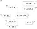
请参考图3,图3是本公开实施例提供的一种车辆的结构框图。该车辆300可以包括:VCU 301、油门踏板302、MCU 303、驱动电机304、危险警报灯305、车身控制器306、刹车灯307以及制动踏板308。Please refer to FIG. 3 , which is a structural block diagram of a vehicle provided by an embodiment of the present disclosure. The
示例的,当驾驶员踩下制动踏板308时,制动踏板308可以向车辆300发送制动信号,此时,VCU 301可以检测到车辆300接收到制动信号,VCU 301可以控制刹车灯点亮;当驾驶员未踩下制动踏板308时,制动踏板308可以停止向车辆300发送制动信号,此时,VCU 301可以检测到车辆300未接收到制动信号,执行步骤202。For example, when the driver depresses the
步骤202、若检测到车辆未接收到制动信号,检测车辆中的驱动电机的转速降低是否降低。Step 202: If it is detected that the vehicle does not receive a braking signal, it is detected whether the speed of the driving motor in the vehicle decreases.
在本公开实施例中,若VCU检测到车辆未接收到制动信号,VCU检测车辆中的驱动电机的转速是否降低。示例的,当VCU检测到车辆中的驱动电机的转速降低时,执行步骤203;当VCU检测到车辆中的驱动电机的转速未降低时,重复执行步骤201。In the embodiment of the present disclosure, if the VCU detects that the vehicle does not receive a braking signal, the VCU detects whether the rotational speed of the drive motor in the vehicle decreases. For example, when the VCU detects that the rotational speed of the drive motor in the vehicle decreases, step 203 is performed; when the VCU detects that the rotational speed of the drive motor in the vehicle does not decrease,
在本公开实施例中,VCU检测车辆中的驱动电机的转速是否降低有多种可实现方式,本公开实施例以以下四种可实现方式为例进行示意性的说明:In the embodiment of the present disclosure, there are multiple implementations for the VCU to detect whether the rotational speed of the drive motor in the vehicle is reduced. The embodiment of the present disclosure takes the following four implementations as examples for schematic illustration:
在第一种可实现方式中,VCU检测车辆中的驱动电机的转速是否降低可以包括以下几个步骤:In the first implementation manner, the VCU detecting whether the rotational speed of the drive motor in the vehicle decreases may include the following steps:
步骤A1、检测车辆中的MCU的高压电源端与车辆中的电池包之间的电连接是否断开。Step A1: Detect whether the electrical connection between the high-voltage power supply terminal of the MCU in the vehicle and the battery pack in the vehicle is disconnected.
在本公开实施例中,VCU可以检测车辆中的MCU的高压电源端与车辆中的电池包之间的电连接是否断开。示例的,当VCU检测到车辆中的MCU的高压电源端与车辆中的电池包之间的电连接断开时,VCU可以确定出MCU出现故障,此时,执行步骤B1;当VCU检测到车辆中的MCU的高压电源端与车辆中的电池包之间的电连接未断开时,重复执行步骤201。In the embodiment of the present disclosure, the VCU can detect whether the electrical connection between the high-voltage power supply terminal of the MCU in the vehicle and the battery pack in the vehicle is disconnected. For example, when the VCU detects that the electrical connection between the high-voltage power supply terminal of the MCU in the vehicle and the battery pack in the vehicle is disconnected, the VCU can determine that the MCU is faulty, and at this time, step B1 is performed; when the VCU detects that the vehicle is faulty When the electrical connection between the high-voltage power supply terminal of the MCU in the MCU and the battery pack in the vehicle is not disconnected,
可选的,如图3所述,VCU 301可以检测MCU 303的高压电源端是否发出高压电平信号,以判断车辆300中的MCU 303的高压电源端与车辆300中的电池包之间的电连接是否断开。示例的,当VCU 301检测到MCU 303的高压电源端未发出高压电平信号时,VCU 301可以确定出车辆300中的MCU 303的高压电源端与车辆300中的电池包之间的电连接断开,执行步骤B1;当VCU 301检测到MCU 303的高压电源端发出高压电平信号时,车辆300中的MCU303的高压电源端与车辆300中的电池包之间的电连接连通,重复执行步骤201。Optionally, as shown in FIG. 3 , the
步骤B1、若检测到车辆中的MCU的高压电源端与车辆中的电池包之间的电连接断开,确定车辆中的驱动电机的转速降低。Step B1, if it is detected that the electrical connection between the high-voltage power supply terminal of the MCU in the vehicle and the battery pack in the vehicle is disconnected, it is determined that the rotational speed of the driving motor in the vehicle is reduced.
在本公开实施例中,若VCU检测到车辆中的MCU的高压电源端与车辆中的电池包之间的电连接断开,VCU可以确定出车辆中的驱动电机的转速降低,此时,执行步骤203。In the embodiment of the present disclosure, if the VCU detects that the electrical connection between the high-voltage power supply terminal of the MCU in the vehicle and the battery pack in the vehicle is disconnected, the VCU can determine that the rotational speed of the driving motor in the vehicle is reduced, and at this time, execute Step 203.
在第二种可实现方式中,VCU检测车辆中的驱动电机的转速是否降低可以包括以下几个步骤:In a second implementation manner, the VCU detecting whether the rotational speed of the drive motor in the vehicle decreases may include the following steps:
步骤A2、检测VCU与车辆中的MCU之间的通信连接是否断开。Step A2: Detect whether the communication connection between the VCU and the MCU in the vehicle is disconnected.
在本公开实施例中,VCU可以检测VCU与车辆中的MCU之间的通信连接是否断开。示例的,当VCU检测到VCU与车辆中的MCU之间的通信连接断开时,VCU可以确定出MCU出现故障,此时,执行步骤B2;当VCU检测到VCU与车辆中的MCU之间的通信连接未断开时,重复执行步骤201。In the embodiment of the present disclosure, the VCU may detect whether the communication connection between the VCU and the MCU in the vehicle is disconnected. For example, when the VCU detects that the communication connection between the VCU and the MCU in the vehicle is disconnected, the VCU can determine that the MCU is faulty, and at this time, step B2 is performed; when the VCU detects that the communication between the VCU and the MCU in the vehicle is disconnected When the communication connection is not disconnected,
可选的,如图3所示,VCU 301可以周期性的向MCU 303发送第一心跳包,在MCU 303接收到第一心跳包后,该MCU 303可以基于该第一心跳包生成第一心跳反馈包,该第一心跳反馈包用于向VCU 301指示MCU 303和VCU 301之间的通信连接正常。VCU可以检测在预设时长内是否接受到MCU发送的第一心跳反馈包,以判断VCU 301与车辆300中的MCU 303之间的通信连接是否断开。示例的,当VCU 301检测到预设时长内未接收到MCU 303发送的第一心跳反馈包时,VCU 301可以确定VCU 301与车辆300中的MCU 303之间的通信连接断开,执行步骤B2;当VCU 301检测到预设时长内接收到MCU 303发送的第一心跳反馈包时,VCU 301可以确定VCU 301与车辆300中的MCU 303之间的通信连接未断开,重复执行步骤201。Optionally, as shown in FIG. 3 , the
步骤B2、若检测到VCU与车辆中的MCU之间的通信连接断开,确定车辆中的驱动电机的转速降低。Step B2: If it is detected that the communication connection between the VCU and the MCU in the vehicle is disconnected, it is determined that the rotational speed of the driving motor in the vehicle is reduced.
在本公开实施例中,若VCU检测到VCU与车辆中的MCU之间的通信连接断开,VCU可以确定出车辆中的驱动电机的转速降低,此时,执行步骤203。In the embodiment of the present disclosure, if the VCU detects that the communication connection between the VCU and the MCU in the vehicle is disconnected, the VCU may determine that the rotational speed of the driving motor in the vehicle is reduced, and in this case, step 203 is performed.
在第三种可实现方式中,VCU检测车辆中的驱动电机的转速是否降低可以包括以下几个步骤:In a third achievable manner, the VCU detecting whether the rotational speed of the drive motor in the vehicle decreases may include the following steps:
A3、检测车辆中的MCU与车辆中的驱动电机之间的通信连接是否断开。A3. Detect whether the communication connection between the MCU in the vehicle and the drive motor in the vehicle is disconnected.
在本公开实施例中,VCU可以车辆中的MCU与车辆中的驱动电机之间的通信连接是否断开。示例的,当VCU检测到车辆中的MCU与车辆中的驱动电机之间的通信连接断开时,VCU可以确定出MCU或驱动电机出现故障,此时,执行步骤B3;当VCU检测到车辆中的MCU与车辆中的驱动电机之间的通信连接未断开时,重复执行步骤201。In the embodiment of the present disclosure, the VCU can determine whether the communication connection between the MCU in the vehicle and the drive motor in the vehicle is disconnected. For example, when the VCU detects that the communication connection between the MCU in the vehicle and the drive motor in the vehicle is disconnected, the VCU can determine that the MCU or the drive motor is faulty, and at this time, step B3 is performed; When the communication connection between the MCU and the drive motor in the vehicle is not disconnected,
可选的,如图3所示,MCU 303可以周期性的向驱动电机304发送第二心跳包,在驱动电机304接收到第二心跳包后,该驱动电机304可以基于该第二心跳包生成第二心跳反馈包,该第二心跳反馈包用于向MCU 303指示MCU 303和驱动电机304之间的通信连接正常。MCU 303可以检测在预设时长内是否接受到驱动电机304发送的第二心跳反馈包,以判断MCU 303与驱动电机304之间的通信连接是否断开。示例的,当MCU 303检测到预设时长内未接收到驱动电机304发送的第二心跳反馈包时,MCU 303可以确定MCU 303与驱动电机304之间的通信连接断开;当MCU 303检测到预设时长内接收到驱动电机304发送的第二心跳反馈包时,MCU 303可以确定MCU 303与驱动电机304之间的通信连接未断开。Optionally, as shown in FIG. 3, the
其中,当MCU 303与驱动电机304之间的通信连接断开时,有以下三种情况:MCU303无法周期性的向驱动电机304发送第二心跳包;或者驱动电机304无法基于该第二心跳包生成第二心跳反馈包;或者MCU 303无法周期性的向驱动电机304发送第二心跳包,且驱动电机304无法基于第二心跳包生成第二心跳反馈包。上述情况均可造成车辆300中的MCU303与车辆300中的驱动电机304之间的通信连接断开。Wherein, when the communication connection between the
在MCU检测出MCU与驱动电机之间的通信连接断开时,MCU可以向VCU发送用于指示MCU和驱动电机之间的通信连接断开的指示信息。因此,VCU可以检测是否接收到MCU发送的指示信息,以判断车辆中的MCU与驱动电机之间的通信连接是否断开。示例的,当VCU接收到了MCU发送的指示信息时,VCU可以确定出车辆中的MCU与驱动电机之间的通信连接断开,执行步骤B3;当VCU未接收到了MCU发送的指示信息时,VCU可以确定出车辆中的MCU与驱动电机之间的通信连接未断开,重复执行步骤201。When the MCU detects that the communication connection between the MCU and the driving motor is disconnected, the MCU may send the instruction information to the VCU for indicating that the communication connection between the MCU and the driving motor is disconnected. Therefore, the VCU can detect whether the instruction information sent by the MCU is received, so as to determine whether the communication connection between the MCU in the vehicle and the drive motor is disconnected. For example, when the VCU receives the instruction information sent by the MCU, the VCU can determine that the communication connection between the MCU in the vehicle and the drive motor is disconnected, and execute step B3; when the VCU does not receive the instruction information sent by the MCU, the VCU It can be determined that the communication connection between the MCU in the vehicle and the drive motor is not disconnected, and step 201 is repeated.
B3、若检测到车辆中的MCU与车辆中的驱动电机之间的通信连接断开,确定车辆中的驱动电机的转速降低。B3. If it is detected that the communication connection between the MCU in the vehicle and the driving motor in the vehicle is disconnected, determine that the rotational speed of the driving motor in the vehicle is reduced.
在本公开实施例中,若VCU检测到车辆中的MCU与车辆中的驱动电机之间的通信连接断开,VCU可以确定出车辆中的驱动电机的转速降低,此时,执行步骤203。In the embodiment of the present disclosure, if the VCU detects that the communication connection between the MCU in the vehicle and the driving motor in the vehicle is disconnected, the VCU may determine that the rotational speed of the driving motor in the vehicle is reduced, and in this case, step 203 is performed.
在第四种可实现方式中,VCU检测车辆中的驱动电机的转速是否降低可以包括以下几个步骤:In a fourth achievable manner, the VCU detecting whether the rotational speed of the drive motor in the vehicle decreases may include the following steps:
A4、检测车辆是否接收到油门信号。A4. Detect whether the vehicle receives the accelerator signal.
在本公开实施例中,VCU可以检测车辆是否接受到油门信号。示例的,当VCU检测到车辆未接受到油门信号时,执行步骤B4;当VCU检测到车辆接受到油门信号时,重复执行步骤201。In the embodiment of the present disclosure, the VCU can detect whether the vehicle receives an accelerator signal. For example, when the VCU detects that the vehicle does not receive the accelerator signal, step B4 is performed; when the VCU detects that the vehicle receives the accelerator signal,
可选的,如图3所示,当驾驶员踩下油门踏板302时,油门踏板302可以向车辆300发送油门信号,此时,VCU 301可以检测到车辆300接收到油门信号,重复执行步骤201;当驾驶员未踩下油门踏板302时,油门踏板302可以向车辆300停止发送油门信号,此时,VCU 301可以检测到车辆300未接收到油门信号,执行步骤B4。Optionally, as shown in FIG. 3 , when the driver steps on the
B4、若检测到车辆未接收到油门信号,确定车辆中的驱动电机的转速降低。B4. If it is detected that the vehicle does not receive the accelerator signal, it is determined that the rotational speed of the driving motor in the vehicle is reduced.
在本公开实施例中,若VCU检测到车辆中的油门踏板未被踩,VCU可以确定出车辆中的驱动电机的转速较低,此时,执行步骤203。In the embodiment of the present disclosure, if the VCU detects that the accelerator pedal in the vehicle is not stepped on, the VCU may determine that the rotational speed of the driving motor in the vehicle is low, and in this case, step 203 is performed.
需要说明的是,若通过上述第一种可实现方式、第二种可实现方式或第三种可实现方式,VCU确定出驱动电机的转速降低,则VCU可以确定出车辆中的MCU或驱动电机出现了故障;若通过上述第四种可实现方式VCU确定出驱动电机的转速降低,则VCU可以确定出驾驶员未踩下车辆中的油门踏板。It should be noted that, if the VCU determines that the rotational speed of the drive motor is reduced through the first, second, or third achievable methods described above, the VCU can determine the MCU or the drive motor in the vehicle. A fault has occurred; if the VCU determines that the rotational speed of the drive motor is reduced through the fourth implementation manner described above, the VCU can determine that the driver has not stepped on the accelerator pedal in the vehicle.
步骤203、当检测到车辆中的驱动电机的转速降低时,控制刹车灯点亮。Step 203 , when it is detected that the rotational speed of the drive motor in the vehicle decreases, control the brake light to turn on.
在本公开实施例中,当VCU检测到车辆中的驱动电机的转速降低时,VCU可以控制刹车灯点亮,可以为在该车辆后方行驶的车辆和行人指明其处于制动状态,进而降低了车辆行驶中的发生安全事故的概率。In the embodiment of the present disclosure, when the VCU detects that the rotational speed of the drive motor in the vehicle decreases, the VCU can control the brake light to light up, which can indicate that the vehicle and pedestrians behind the vehicle are in a braking state, thereby reducing the speed of the vehicle. The probability of a safety accident while the vehicle is in motion.
步骤204、发出用于指示车辆出现故障的提示信息。Step 204: Send out a prompt message for indicating that the vehicle is faulty.
在本公开实施例中,VCU在检测到刹车灯未接收到制动信号,且检测到由MCU或驱动电机出现故障而引发的驱动电机的转速降低时,VCU可以发出用于指示车辆出现故障的提示信息。该提示信息可以对驾驶员进行提示,以使驾驶员了解到MCU或驱动电机出现了故障。In the embodiment of the present disclosure, when the VCU detects that the brake light does not receive the braking signal, and detects that the rotational speed of the driving motor is reduced due to the failure of the MCU or the driving motor, the VCU may issue a message indicating the failure of the vehicle. prompt information. The prompt information can prompt the driver, so that the driver knows that the MCU or the drive motor is faulty.
可选的,该提示信息可以为音频信息和/或文字信息。当提示信息为音频信息时,VCU可以控制车辆中的音频播放器播放该提示信息;当提示信息为文字信息时,VCU可以控制车辆中的显示设备显示该提示信息。Optionally, the prompt information may be audio information and/or text information. When the prompt information is audio information, the VCU can control the audio player in the vehicle to play the prompt information; when the prompt information is text information, the VCU can control the display device in the vehicle to display the prompt information.
本公开实施例中,在上述步骤201至步骤204的基础上,该刹车灯的控制方法还可以包括:当接收到危险警报灯启动信号时,控制刹车灯点亮。In the embodiment of the present disclosure, on the basis of the
示例的,如图3所示,若驾驶员按下危险报警灯305,该危险报警灯305可以向车身控制器306发送危险警报灯305启动信号,该车身控制器306可以将危险警报灯305启动信号转发给VCU 301。此时,VCU 301可以在接收到危险警报灯305启动信号后,控制刹车灯307点亮。从而可以为位于该车辆300后方的车辆进行提示,降低了发生交通事故的概率。For example, as shown in FIG. 3 , if the driver presses down the
需要说明的是,本公开实施例提供的刹车灯的控制方法步骤的先后顺序可以进行适当调整,步骤也可以根据情况进行相应增减,任何熟悉本技术领域的技术人员在本公开揭露的技术范围内,可轻易想到变化的方法,都应涵盖在本公开的保护范围之内,因此不再赘述。It should be noted that the sequence of steps of the brake light control method provided by the embodiments of the present disclosure can be appropriately adjusted, and the steps can also be increased or decreased according to the situation. Within the scope of the present disclosure, any method that can be easily imagined changes should be covered within the protection scope of the present disclosure, and thus will not be repeated here.
综上所述,本公开实施例提供的刹车灯的控制方法,通过检测车辆是否接收到制动信号,若检测到车辆未接收到制动信号,当检测到车辆中的驱动电机的转速降低时,控制车辆中的刹车灯点亮。刹车灯不仅可以在驾驶员踩下制动板时被点亮,也可以在驾驶员未踩下制动板,但在车辆中的驱动电机的转速降低时被点亮,有效的丰富了刹车灯的功能。并且,在车辆中的驱动电机或MCU出现故障时,控制车辆中刹车灯点亮,或者,在驾驶员未踩车辆中的油门踏板时,控制车辆中的刹车灯点亮,可以为在该车辆后方行驶的车辆和行人指明其处于制动状态,进而降低了车辆行驶中的发生安全事故的概率。To sum up, the control method for a brake light provided by an embodiment of the present disclosure detects whether the vehicle receives a braking signal. If it is detected that the vehicle does not receive a braking signal, when it is detected that the speed of the driving motor in the vehicle decreases , to control the brake lights in the vehicle to illuminate. The brake light can be illuminated not only when the driver steps on the brake pad, but also when the driver does not step on the brake pad, but when the speed of the drive motor in the vehicle decreases, effectively enriching the brake lights. function. In addition, when the drive motor or MCU in the vehicle fails, control the brake light in the vehicle to light up, or control the brake light in the vehicle to light up when the driver does not step on the accelerator pedal in the vehicle. Vehicles and pedestrians driving behind indicate that they are in a braking state, thereby reducing the probability of a safety accident while the vehicle is driving.
下述为本公开装置实施例,可以用于执行本公开方法实施例。对于本公开装置实施例中未披露的细节,请参照本公开方法实施例。The following are the apparatus embodiments of the present disclosure, which can be used to execute the method embodiments of the present disclosure. For details not disclosed in the apparatus embodiments of the present disclosure, please refer to the method embodiments of the present disclosure.
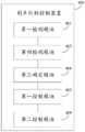
请参考图4,图4是本公开实施例提供的一种刹车灯的控制装置的结构框图。该刹车灯的控制装置可以应用于车辆中的VCU,该刹车灯的控制装置400可以包括:Please refer to FIG. 4 , which is a structural block diagram of a control device for a brake light provided by an embodiment of the present disclosure. The control device for the brake light may be applied to a VCU in a vehicle, and the
第一检测模块401,用于在车辆正常行驶时,检测车辆是否接收到制动信号。The
第一控制模块402,用于若检测到车辆未接收到制动信号,当检测到车辆中的驱动电机的转速降低时,控制车辆中的刹车灯点亮。The
综上所述,本公开实施例提供的刹车灯的控制装置,通过检测车辆是否接收到制动信号,若检测到车辆未接收到制动信号,当检测到车辆中的驱动电机的转速降低时,控制车辆中的刹车灯点亮。刹车灯不仅可以在驾驶员踩下制动板时被点亮,也可以在驾驶员未踩下制动板,但在车辆中的驱动电机的转速降低时被点亮,有效的丰富了刹车灯的功能。并且,在车辆中的驱动电机或MCU出现故障时,控制车辆中刹车灯点亮,或者,在驾驶员未踩车辆中的油门踏板时,控制车辆中的刹车灯点亮,可以为在该车辆后方行驶的车辆和行人指明其处于制动状态,进而降低了车辆行驶中的发生安全事故的概率。To sum up, the control device for a brake light provided by the embodiment of the present disclosure detects whether the vehicle receives a braking signal. , to control the brake lights in the vehicle to illuminate. The brake light can be illuminated not only when the driver steps on the brake pad, but also when the driver does not step on the brake pad, but when the speed of the drive motor in the vehicle decreases, effectively enriching the brake lights. function. In addition, when the drive motor or MCU in the vehicle fails, control the brake light in the vehicle to light up, or control the brake light in the vehicle to light up when the driver does not step on the accelerator pedal in the vehicle. Vehicles and pedestrians driving behind indicate that they are in a braking state, thereby reducing the probability of a safety accident while the vehicle is driving.
可选的,请参考图5,图5是本公开实施例提供的另一种刹车灯的控制装置的结构框图。该刹车灯的控制装置400还可以包括:Optionally, please refer to FIG. 5. FIG. 5 is a structural block diagram of another brake light control apparatus provided by an embodiment of the present disclosure. The
第二检测模块403,用于检测车辆中的电机控制器MCU的高压电源端与车辆中的电池包之间的电连接是否断开。The
第一确定模块404,用于若检测到车辆中的MCU与车辆中的电池包之间的连接断开,确定车辆中的驱动电机的转速降低。The first determining
可选的,请参考图6,图6是本公开实施例提供的又一种刹车灯的控制装置的结构框图。该刹车灯的控制装置400还可以包括:Optionally, please refer to FIG. 6 . FIG. 6 is a structural block diagram of another apparatus for controlling a brake light provided by an embodiment of the present disclosure. The
第三检测模块405,用于检测VCU与车辆中的MCU之间的通信连接是否断开。The
第二确定模块406,用于若检测到VCU与车辆中的MCU之间的通信连接断开,确定车辆中的驱动电机的转速降低。The
可选的,请参考图7,图7是本公开实施例提供的再一种刹车灯的控制装置的结构框图。该刹车灯的控制装置400还可以包括:Optionally, please refer to FIG. 7 , which is a structural block diagram of still another brake light control device provided by an embodiment of the present disclosure. The
第四检测模块407,用于检测所述车辆中的MCU与所述车辆中的驱动电机之间的通信连接是否断开。The
第三确定模块408,用于若检测到车辆中的MCU与车辆中的驱动电机之间的通信连接断开,确定车辆中的驱动电机的转速降低。The third determining
可选的,请参考图4至图7,在上述刹车灯的控制装置400的基础上,该刹车灯的控制装置400还可以包括:第二控制模块409,用于当接收到危险警报灯启动信号时,控制所述刹车灯点亮。Optionally, please refer to FIG. 4 to FIG. 7 , on the basis of the above-mentioned
综上所述,本公开实施例提供的刹车灯的控制装置,通过检测车辆是否接收到制动信号,若检测到车辆未接收到制动信号,当检测到车辆中的驱动电机的转速降低时,控制车辆中的刹车灯点亮。刹车灯不仅可以在驾驶员踩下制动板时被点亮,也可以在驾驶员未踩下制动板,但在车辆中的驱动电机的转速降低时被点亮,有效的丰富了刹车灯的功能。并且,在车辆中的驱动电机或MCU出现故障时,控制车辆中刹车灯点亮,或者,在驾驶员未踩车辆中的油门踏板时,控制车辆中的刹车灯点亮,可以为在该车辆后方行驶的车辆和行人指明其处于制动状态,进而降低了车辆行驶中的发生安全事故的概率。To sum up, the control device for a brake light provided by the embodiment of the present disclosure detects whether the vehicle receives a braking signal. , to control the brake lights in the vehicle to illuminate. The brake light can be illuminated not only when the driver steps on the brake pad, but also when the driver does not step on the brake pad, but when the speed of the drive motor in the vehicle decreases, effectively enriching the brake lights. function. In addition, when the drive motor or MCU in the vehicle fails, control the brake light in the vehicle to light up, or control the brake light in the vehicle to light up when the driver does not step on the accelerator pedal in the vehicle. Vehicles and pedestrians driving behind indicate that they are in a braking state, thereby reducing the probability of a safety accident while the vehicle is driving.
所属领域的技术人员可以清楚地了解到,为描述的方便和简洁,上述描述的装置和模块的具体工作过程,可以参考前述方法实施例中的对应过程,在此不再赘述。Those skilled in the art can clearly understand that, for the convenience and brevity of description, for the specific working process of the above-described devices and modules, reference may be made to the corresponding processes in the foregoing method embodiments, which will not be repeated here.
本公开实施例还提供了一种计算机可读存储介质,该存储介质为非易失性存储介质,该存储介质中存储有代码指令,该代码指令由处理器执行,以执行图1或图2示出的刹车灯的控制方法。An embodiment of the present disclosure further provides a computer-readable storage medium, which is a non-volatile storage medium, and stores code instructions in the storage medium, and the code instructions are executed by a processor to execute FIG. 1 or FIG. 2 The control method of the brake light is shown.
本公开实施例还提供了一种车辆。该车辆包括:至少一个处理器;和至少一个存储器;Embodiments of the present disclosure also provide a vehicle. The vehicle includes: at least one processor; and at least one memory;
其中,该至少一个存储器存储有一个或多个程序;Wherein, the at least one memory stores one or more programs;
至少一个处理器,用于执行至少一个存储器上所存储的程序,以实现图1或图2示出的刹车灯的控制方法。At least one processor is configured to execute a program stored in at least one memory, so as to implement the control method of the brake light shown in FIG. 1 or FIG. 2 .
在本公开中,术语“第一”和“第二”仅用于描述目的,而不能理解为指示或暗示相对重要性。术语“多个”指两个或两个以上,除非另有明确的限定。In this disclosure, the terms "first" and "second" are used for descriptive purposes only and should not be construed to indicate or imply relative importance. The term "plurality" refers to two or more, unless expressly limited otherwise.
本领域普通技术人员可以理解实现上述实施例的全部或部分步骤可以通过硬件来完成,也可以通过程序来指令相关的硬件完成,所述的程序可以存储于一种计算机可读存储介质中,上述提到的存储介质可以是只读存储器,磁盘或光盘等。Those of ordinary skill in the art can understand that all or part of the steps of implementing the above embodiments can be completed by hardware, or can be completed by instructing relevant hardware through a program, and the program can be stored in a computer-readable storage medium. The storage medium mentioned may be a read-only memory, a magnetic disk or an optical disk, etc.
以上所述仅为本公开的可选的实施例,并不用以限制本公开,凡在本公开的精神和原则之内,所作的任何修改、等同替换、改进等,均应包含在本公开的保护范围之内。The above descriptions are only optional embodiments of the present disclosure, and are not intended to limit the present disclosure. Any modifications, equivalent replacements, improvements, etc. made within the spirit and principles of the present disclosure shall be included in the scope of the present disclosure. within the scope of protection.
Claims (8)
Translated fromChinesePriority Applications (1)
| Application Number | Priority Date | Filing Date | Title |
|---|---|---|---|
| CN201911337883.4ACN110861576B (en) | 2019-12-23 | 2019-12-23 | Control method and device of brake lamp |
Applications Claiming Priority (1)
| Application Number | Priority Date | Filing Date | Title |
|---|---|---|---|
| CN201911337883.4ACN110861576B (en) | 2019-12-23 | 2019-12-23 | Control method and device of brake lamp |
Publications (2)
| Publication Number | Publication Date |
|---|---|
| CN110861576A CN110861576A (en) | 2020-03-06 |
| CN110861576Btrue CN110861576B (en) | 2022-06-07 |
Family
ID=69659173
Family Applications (1)
| Application Number | Title | Priority Date | Filing Date |
|---|---|---|---|
| CN201911337883.4AActiveCN110861576B (en) | 2019-12-23 | 2019-12-23 | Control method and device of brake lamp |
Country Status (1)
| Country | Link |
|---|---|
| CN (1) | CN110861576B (en) |
Families Citing this family (1)
| Publication number | Priority date | Publication date | Assignee | Title |
|---|---|---|---|---|
| CN114454810B (en)* | 2022-02-25 | 2023-08-25 | 重庆金康赛力斯新能源汽车设计院有限公司 | A new energy vehicle tail light warning control method, a device based on the method, and a vehicle |
Citations (9)
| Publication number | Priority date | Publication date | Assignee | Title |
|---|---|---|---|---|
| KR20020011465A (en)* | 2000-08-02 | 2002-02-09 | 류정열 | Tail lamp operating apparatus of vehicle |
| CN102371940A (en)* | 2010-08-13 | 2012-03-14 | 彭国智 | Automobile multifunctional flasher |
| CN102514493A (en)* | 2011-12-16 | 2012-06-27 | 奇瑞汽车股份有限公司 | Safe torque monitoring method for electric vehicle |
| CN102658794A (en)* | 2012-05-09 | 2012-09-12 | 重庆桴之科科技发展有限公司 | Device and method for turning on brake lamp in advance to prevent automobile rear-end collision |
| CN103747571A (en)* | 2013-12-25 | 2014-04-23 | 浙江吉利控股集团有限公司 | Vehicle speed based brake lamp automatic control method and control apparatus |
| CN203567620U (en)* | 2013-11-06 | 2014-04-30 | 吉林大学 | Automobile brake light and automobile |
| CN104723888A (en)* | 2013-12-18 | 2015-06-24 | 博世汽车部件(苏州)有限公司 | Motor vehicle regenerative control and brake lamp control |
| CN104828073A (en)* | 2014-04-10 | 2015-08-12 | 北汽福田汽车股份有限公司 | Vehicle control method and system |
| CN110316048A (en)* | 2019-07-24 | 2019-10-11 | 重庆长安汽车股份有限公司 | A kind of electric car brake lamp control method, system and automobile |
- 2019
- 2019-12-23CNCN201911337883.4Apatent/CN110861576B/enactiveActive
Patent Citations (9)
| Publication number | Priority date | Publication date | Assignee | Title |
|---|---|---|---|---|
| KR20020011465A (en)* | 2000-08-02 | 2002-02-09 | 류정열 | Tail lamp operating apparatus of vehicle |
| CN102371940A (en)* | 2010-08-13 | 2012-03-14 | 彭国智 | Automobile multifunctional flasher |
| CN102514493A (en)* | 2011-12-16 | 2012-06-27 | 奇瑞汽车股份有限公司 | Safe torque monitoring method for electric vehicle |
| CN102658794A (en)* | 2012-05-09 | 2012-09-12 | 重庆桴之科科技发展有限公司 | Device and method for turning on brake lamp in advance to prevent automobile rear-end collision |
| CN203567620U (en)* | 2013-11-06 | 2014-04-30 | 吉林大学 | Automobile brake light and automobile |
| CN104723888A (en)* | 2013-12-18 | 2015-06-24 | 博世汽车部件(苏州)有限公司 | Motor vehicle regenerative control and brake lamp control |
| CN103747571A (en)* | 2013-12-25 | 2014-04-23 | 浙江吉利控股集团有限公司 | Vehicle speed based brake lamp automatic control method and control apparatus |
| CN104828073A (en)* | 2014-04-10 | 2015-08-12 | 北汽福田汽车股份有限公司 | Vehicle control method and system |
| CN110316048A (en)* | 2019-07-24 | 2019-10-11 | 重庆长安汽车股份有限公司 | A kind of electric car brake lamp control method, system and automobile |
Also Published As
| Publication number | Publication date |
|---|---|
| CN110861576A (en) | 2020-03-06 |
Similar Documents
| Publication | Publication Date | Title |
|---|---|---|
| KR101547938B1 (en) | Driving Sound Generating System for Environment Friendly Vehicle and a method for controlling the system | |
| CN107499137B (en) | The electrification control method and device of vehicle | |
| CN113232640A (en) | Vacuum failure auxiliary brake control system of electric automobile | |
| CN112060911B (en) | Low-voltage power supply abnormal driving control method, device and medium for new energy automobile | |
| CN115817204B (en) | Abnormal launch start processing method, device, storage medium and electric vehicle | |
| CN110539643A (en) | Method and device for controlling high voltage of electric automobile | |
| CN110861576B (en) | Control method and device of brake lamp | |
| CN117755083A (en) | A method, device, equipment and storage medium for determining the power-off delay time | |
| CN115042626B (en) | Ignition switch power-off protection control circuit and method for electric vehicles | |
| US20220345065A1 (en) | Control device for rotating electrical machine | |
| CN114590236B (en) | Electric vehicle control method and device, storage medium and vehicle | |
| CN219601224U (en) | Redundant brake system and vehicle for control-by-wire chassis | |
| CN114454810A (en) | New energy vehicle tail lamp warning control method, device based on method and vehicle | |
| CN105329236B (en) | A kind of Powertrain control method, apparatus and system | |
| JP6634772B2 (en) | Stop lamp failure detection device | |
| CN114074552A (en) | Fuel cell automobile insulation detection method and vehicle control unit | |
| CN116494943A (en) | Dual-backup vehicle braking system and vehicle | |
| CN113547934B (en) | An energy recovery method, device, storage medium and vehicle controller | |
| CN206436906U (en) | A kind of vehicle intelligent horn system | |
| CN115257541A (en) | Vehicle brake lamp failure control method and system | |
| CN115092080A (en) | Method, system and electric vehicle for fault classification prompting of vehicle power system | |
| CN115742996A (en) | Limping control method based on vehicle body control system | |
| CN114103659A (en) | A kind of electric vehicle energy consumption optimization method and control system | |
| CN107097716A (en) | Car bulb failure alternative | |
| CN113815527A (en) | Brake lamp control method and system of pure electric vehicle and pure electric vehicle |
Legal Events
| Date | Code | Title | Description |
|---|---|---|---|
| PB01 | Publication | ||
| PB01 | Publication | ||
| SE01 | Entry into force of request for substantive examination | ||
| SE01 | Entry into force of request for substantive examination | ||
| GR01 | Patent grant | ||
| GR01 | Patent grant | ||
| OL01 | Intention to license declared | ||
| OL01 | Intention to license declared |