CN110859418A - Shelf and cloakroom with suspension structure - Google Patents
Shelf and cloakroom with suspension structureDownload PDFInfo
- Publication number
- CN110859418A CN110859418ACN201911017509.6ACN201911017509ACN110859418ACN 110859418 ACN110859418 ACN 110859418ACN 201911017509 ACN201911017509 ACN 201911017509ACN 110859418 ACN110859418 ACN 110859418A
- Authority
- CN
- China
- Prior art keywords
- shelf
- clothes
- fastener
- suspension structure
- slot
- Prior art date
- Legal status (The legal status is an assumption and is not a legal conclusion. Google has not performed a legal analysis and makes no representation as to the accuracy of the status listed.)
- Pending
Links
Images


Classifications
- A—HUMAN NECESSITIES
- A47—FURNITURE; DOMESTIC ARTICLES OR APPLIANCES; COFFEE MILLS; SPICE MILLS; SUCTION CLEANERS IN GENERAL
- A47B—TABLES; DESKS; OFFICE FURNITURE; CABINETS; DRAWERS; GENERAL DETAILS OF FURNITURE
- A47B61/00—Wardrobes
- A—HUMAN NECESSITIES
- A47—FURNITURE; DOMESTIC ARTICLES OR APPLIANCES; COFFEE MILLS; SPICE MILLS; SUCTION CLEANERS IN GENERAL
- A47B—TABLES; DESKS; OFFICE FURNITURE; CABINETS; DRAWERS; GENERAL DETAILS OF FURNITURE
- A47B45/00—Cabinets, racks or shelf units, characterised by features enabling enlarging in height, length, or depth
- A—HUMAN NECESSITIES
- A47—FURNITURE; DOMESTIC ARTICLES OR APPLIANCES; COFFEE MILLS; SPICE MILLS; SUCTION CLEANERS IN GENERAL
- A47B—TABLES; DESKS; OFFICE FURNITURE; CABINETS; DRAWERS; GENERAL DETAILS OF FURNITURE
- A47B47/00—Cabinets, racks or shelf units, characterised by features related to dismountability or building-up from elements
- A—HUMAN NECESSITIES
- A47—FURNITURE; DOMESTIC ARTICLES OR APPLIANCES; COFFEE MILLS; SPICE MILLS; SUCTION CLEANERS IN GENERAL
- A47B—TABLES; DESKS; OFFICE FURNITURE; CABINETS; DRAWERS; GENERAL DETAILS OF FURNITURE
- A47B95/00—Fittings for furniture
- A47B95/04—Keyplates; Ornaments or the like
- A—HUMAN NECESSITIES
- A47—FURNITURE; DOMESTIC ARTICLES OR APPLIANCES; COFFEE MILLS; SPICE MILLS; SUCTION CLEANERS IN GENERAL
- A47B—TABLES; DESKS; OFFICE FURNITURE; CABINETS; DRAWERS; GENERAL DETAILS OF FURNITURE
- A47B97/00—Furniture or accessories for furniture, not provided for in other groups of this subclass
Landscapes
- Assembled Shelves (AREA)
Abstract
Translated fromChinese
Description
Translated fromChinese技术领域technical field
本发明属于家装技术领域,涉及一种搁架,和一种具有悬挂结构的搁架及衣帽间。The invention belongs to the technical field of home improvement, and relates to a rack, a rack with a suspension structure, and a cloakroom.
背景技术Background technique
搁板常应用于衣帽间、客厅、书房、也可以用于店面衣服展架、储藏室货架等,除了具有收纳功能,还起到装饰的作用。现有搁板存在以下问题:Shelves are often used in cloakrooms, living rooms, study rooms, and can also be used for storefront clothes display racks, storage room shelves, etc. In addition to the storage function, they also play a decorative role. Existing shelves have the following problems:
1.结构复杂,不易拆装。1. The structure is complex and difficult to disassemble.
2.功能单一,扩展性不好。2. Single function, poor scalability.
发明内容SUMMARY OF THE INVENTION
本发明的目的是针对现有的技术存在上述问题,提出了一种结构简单、功能多样化,并具有悬挂结构的搁架。The purpose of the present invention is to solve the above-mentioned problems in the existing technology, and propose a shelf with a simple structure, diversified functions and a suspension structure.
本发明的目的可通过下列技术方案来实现;The object of the present invention can be achieved through the following technical solutions;
一种具有悬挂结构的搁架,包括:A shelf with a hanging structure, comprising:
至少一块隔板,作为承载结构;at least one bulkhead as the load-bearing structure;
两块侧扣件,分别位于隔板的两侧,且每一个侧扣件与隔板之间凹凸嵌套配合,其中,在每一个侧扣件的一端设置有第一连接部,在每一个侧扣件的另一端设置有第二连接部;The two side fasteners are respectively located on both sides of the partition plate, and each side fastener and the partition plate are in a concave-convex nesting fit, wherein a first connecting portion is provided at one end of each side fastener, and a first connection portion is provided at one end of each side fastener, The other end of the side fastener is provided with a second connecting portion;
若干个第一锁定件,分别位于隔板的两侧,用以固定侧扣件与隔板之间的连接;A plurality of first locking pieces are respectively located on both sides of the partition plate to fix the connection between the side fasteners and the partition plate;
挂衣杆,两端分别与两个侧扣件上的第二连接部相连;a clothes hanger, two ends of which are respectively connected with the second connecting parts on the two side fasteners;
若干个第二锁定件,分别位于挂衣杆的两端,用以固定第二连接部与挂衣杆之间的连接。A plurality of second locking pieces are located at both ends of the clothes hanger, respectively, and are used to fix the connection between the second connection part and the clothes hanger.
在上述的一种具有悬挂结构的搁架中,第一连接部与第二连接部均与侧扣件集成设置,其中,在每一个第二连接部上开设有一个通槽。In the above-mentioned rack with a suspension structure, both the first connecting portion and the second connecting portion are integrally provided with the side fasteners, wherein a through slot is opened on each of the second connecting portions.
在上述的一种具有悬挂结构的搁架中,挂衣杆的两端呈中空状结构设置,其中,第二锁定件的一端依次与第二连接部、挂衣杆的端部嵌套连接。In the above-mentioned rack with a hanging structure, both ends of the clothes hanging rod are arranged in a hollow structure, wherein one end of the second locking member is nested and connected to the second connecting part and the end of the clothes hanging rod in sequence.
在上述的一种具有悬挂结构的搁架中,第二锁定件呈L型结构设置,其中,第二锁定件的一端分别与第二连接部、挂衣杆的端部相嵌套,第二锁定件的另一端与第二连接部的表面相抵靠。In the above-mentioned rack with a hanging structure, the second locking member is arranged in an L-shaped structure, wherein one end of the second locking member is respectively nested with the second connecting portion and the end portion of the clothes hanging rod, and the second locking member The other end of the locking piece abuts against the surface of the second connecting part.
在上述的一种具有悬挂结构的搁架中,在挂衣杆上安装有一条橡胶条。In the above-mentioned rack with a hanging structure, a rubber strip is installed on the clothes rail.
在上述的一种具有悬挂结构的搁架中,沿挂衣杆的长度方向设置有第一条槽和第二条槽,且第一条槽与第二条槽呈上下设置,其中,在第一条槽与第二条槽之间设置有螺纹孔,且第一条槽作为橡胶条的安装位置,第二条槽作为第二锁定件与挂衣杆相嵌套的安装位置,螺纹孔作为固定第二锁定件与挂衣杆时紧固件的连接位置。In the above-mentioned rack with a suspension structure, a first slot and a second slot are arranged along the length direction of the clothes rail, and the first slot and the second slot are arranged up and down, wherein, in the first slot A threaded hole is arranged between the first groove and the second groove, and the first groove is used as the installation position of the rubber strip, the second groove is used as the installation position of the second locking piece and the clothes hanging rod nested, and the threaded hole is used as the installation position of the rubber strip. The connection position of the fastener when the second locking piece and the clothes hanger are fixed.
在上述的一种具有悬挂结构的搁架中,当隔板数量超过一块时,相邻两块隔板之间还设置有一块中扣件,其中,该中扣件的两侧分别与相邻两块隔板之间为凹凸嵌套配合。In the above-mentioned shelf with a suspension structure, when the number of partitions exceeds one, a middle fastener is also provided between two adjacent partitions, wherein the two sides of the middle fastener are respectively adjacent to the adjacent ones. There is a concave-convex nesting fit between the two partitions.
在上述的一种具有悬挂结构的搁架中,在每一个侧扣件的一侧沿水平方向延伸形成一块凸板,在隔板的两侧各设置有一条与凸板嵌套配合的第三条槽。In the above-mentioned shelf with a suspension structure, a convex plate is formed on one side of each side fastener extending in the horizontal direction, and a third plate is arranged on each side of the partition plate to be nested and matched with the convex plate. slot.
在上述的一种具有悬挂结构的搁架中,位于隔板上的第三条槽,其一端呈封闭式结构设置,另一端呈开放式结构设置。In the above-mentioned shelf with a suspension structure, one end of the third slot on the partition is arranged in a closed structure, and the other end is arranged in an open structure.
在上述的一种具有悬挂结构的搁架中,每一个第一锁定件包括一个设置在隔板与侧扣件嵌套位置的弹性插片,和用以锁定隔板与侧扣件的紧固件。In the above-mentioned shelf with a suspension structure, each first locking member includes an elastic insert arranged at the nesting position of the partition plate and the side fastener, and a fastener for locking the partition plate and the side fastener pieces.
在上述的一种具有悬挂结构的搁架中,在弹性插片上至少设置有一个弹性部,其中该弹性部呈斜向设置。In the above-mentioned shelf with a suspension structure, at least one elastic portion is provided on the elastic insert, wherein the elastic portion is arranged obliquely.
在上述的一种具有悬挂结构的搁架中,在弹性部与凸板之间设置有一个定位部,其中,该定位部为凹凸配合结构。In the above-mentioned shelf with a suspension structure, a positioning portion is provided between the elastic portion and the convex plate, wherein the positioning portion is a concave-convex matching structure.
在上述的一种具有悬挂结构的搁架中,该定位部包括开设在凸板上的定位孔,和连接在弹性插片上的定位块。In the above-mentioned shelf with a suspension structure, the positioning portion includes a positioning hole opened on the convex plate, and a positioning block connected to the elastic insert.
在上述的一种具有悬挂结构的搁架中,侧扣件、中扣件的上端面高于隔板的上端面,或者侧扣件、中扣件的上端面与隔板的上端面相平齐。In the above-mentioned shelf with a suspension structure, the upper end surfaces of the side fasteners and the middle fasteners are higher than the upper end surfaces of the partitions, or the upper end surfaces of the side fasteners and the middle fasteners are flush with the upper end surfaces of the partitions. .
在上述的一种具有悬挂结构的搁架中,在侧扣件和中扣件上开设有若干个槽孔。In the above-mentioned rack with a suspension structure, a plurality of slot holes are opened on the side fasteners and the middle fastener.
本发明还提供一种衣帽间,包括:若干个安装于墙体上的扣架,并沿扣架的长度方向设置有若干根立柱,其中,相邻两根立柱之间设置有装饰板,且上述所述的搁架可拆卸连接于立柱上。The present invention also provides a cloakroom, comprising: a plurality of buckle frames installed on the wall, and a plurality of uprights are arranged along the length direction of the buckle frames, wherein a decorative board is arranged between two adjacent uprights, and the above-mentioned The shelf is detachably connected to the upright column.
与现有技术相比,本发明具有以下优点:Compared with the prior art, the present invention has the following advantages:
(1)、本发明提供的一种具有悬挂结构的搁架,其结构简单,拆装方便,且通过侧扣件上的连接部实现搁架的可拆卸固定,可以根据用户身高进行相应的调整,提高搁架的灵活性,另外,通过挂衣杆能够实现衣物的悬挂,避免衣物在首次穿戴时发生褶皱现象,展现衣物的美观。(1) The present invention provides a shelf with a suspension structure, which has a simple structure, is easy to disassemble and assemble, and realizes the detachable fixation of the shelf through the connecting portion on the side fastener, which can be adjusted according to the height of the user. , the flexibility of the shelf is improved, and in addition, the clothes can be hung through the clothes hanger, so that the clothes can be prevented from wrinkling when they are first worn, and the beauty of the clothes can be displayed.
(2)、本发明提供的一种衣帽间,将墙体上的装饰板与搁架集成设置,其中的装饰板不仅作为墙体的装饰板,也可以作为搁架的封板,避免放置于搁架上的衣物与墙体向碰触,使得整个衣帽间的结构更为简洁,另外,装饰板与扣件支架为可拆卸连接,搁架与立柱之间为可拆卸连接,从而实现了安装的方便与快捷。(2) In a cloakroom provided by the present invention, the decorative board on the wall is integrated with the shelf, and the decorative board is not only used as the decorative board of the wall, but also can be used as the sealing board of the shelf to avoid placing it on the shelf. The clothes on the shelf are in contact with the wall, which makes the structure of the entire cloakroom more concise. In addition, the decorative plate and the fastener bracket are detachably connected, and the shelf and the column are detachably connected, thus realizing the convenience of installation. with fast.
附图说明Description of drawings
图1是本发明一种具有悬挂结构的搁架的结构示意图。FIG. 1 is a schematic structural diagram of a shelf with a suspension structure according to the present invention.
图2是本发明一种具有悬挂结构的搁架的局部结构示意图一。FIG. 2 is a partial structural schematic diagram 1 of a shelf with a suspension structure according to the present invention.
图3是本发明一种具有悬挂结构的搁架的局部结构示意图二。FIG. 3 is a second partial structural schematic diagram of a shelf with a suspension structure according to the present invention.
图4是图3中A部分的局部放大图。FIG. 4 is a partial enlarged view of part A in FIG. 3 .
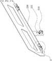
图5是本发明一较佳实施例中挂衣杆的结构示意图。FIG. 5 is a schematic structural diagram of a clothes rail in a preferred embodiment of the present invention.
图6是图5中B部分的局部放大图。FIG. 6 is a partial enlarged view of part B in FIG. 5 .
图7是本发明一较佳实施例中隔板的结构示意图。FIG. 7 is a schematic diagram of the structure of a separator in a preferred embodiment of the present invention.
图8是本发明一种悬挂结构的搁架另一实施例的结构示意图。FIG. 8 is a schematic structural diagram of another embodiment of a shelf with a suspension structure of the present invention.
图9是本发明一种衣帽间的结构示意图。FIG. 9 is a schematic structural diagram of a cloakroom of the present invention.
图10是本发明一种衣帽间的局部示意图。Figure 10 is a partial schematic view of a cloakroom of the present invention.
图11是图10中C部分的放大图。FIG. 11 is an enlarged view of part C in FIG. 10 .
图12是图10中D部分的放大图。FIG. 12 is an enlarged view of part D in FIG. 10 .
图13是本发明一种衣帽间另一实施例的结构示意图。13 is a schematic structural diagram of another embodiment of a cloakroom of the present invention.
图中,100、隔板;110、第三条槽;200、侧扣件;210、第一连接部;211、扣脚;220、第二连接部;221、通槽;230、凸板;231、定位孔;240、槽孔;300、第一锁定件;310、弹性插片;311、弹性部;320、定位块;400、挂衣杆;410、橡胶条;420、第一条槽;430、第二条槽;440、螺纹孔;500、第二锁定件;510、凸块;600、中扣件;700、墙体;800、扣架;810、第一挂板;811、第一支板;812、第一滑槽;813、安装孔;820、托板;821、台阶;830、顶板900、立柱;910、条形凹槽;920、卡接块;1000、装饰板;1100、门板;1200、第二挂板;1210、第二支板;1220、第二滑槽。In the figure, 100, partition; 110, third slot; 200, side fastener; 210, first connection part; 211, buckle foot; 220, second connection part; 221, through groove; 230, convex plate; 231, positioning hole; 240, slot; 300, first locking piece; 310, elastic insert; 311, elastic part; 320, positioning block; 400, clothes rail; 410, rubber strip; 420, first slot ; 430, the second slot; 440, the threaded hole; 500, the second locking piece; 510, the bump; 600, the middle fastener; 700, the wall; 812, first chute; 813, mounting hole; 820, pallet; 821, step; 830,
具体实施方式Detailed ways
以下是本发明的具体实施例并结合附图,对本发明的技术方案作进一步的描述,但本发明并不限于这些实施例。The following are specific embodiments of the present invention and the accompanying drawings to further describe the technical solutions of the present invention, but the present invention is not limited to these embodiments.
实施例一Example 1
如图1至图7所示,本发明提供的一种具有悬挂结构的搁架,包括:至少一块隔板100,作为承载结构;两块侧扣件200,分别位于隔板100的两侧,且每一个侧扣件200与隔板100之间凹凸嵌套配合,其中,在每一个侧扣件200的一端设置有第一连接部210,在每一个侧扣件200的另一端设置有第二连接部220;若干个第一锁定件300,分别位于隔板100的两侧,用以固定侧扣件200与隔板100之间的连接;挂衣杆400,两端分别与两个侧扣件200上的第二连接部220相连;若干个第二锁定件500,分别位于挂衣杆400的两端,用以固定第二连接部220与挂衣杆400之间的连接。As shown in FIG. 1 to FIG. 7 , a shelf with a suspension structure provided by the present invention includes: at least one
本发明提供的一种具有悬挂结构的搁架,其结构简单,拆装方便,且通过侧扣件200上的连接部实现搁架的可拆卸固定,可以根据用户身高进行相应的调整,提高搁架的灵活性,另外,通过挂衣杆400能够实现衣物的悬挂,避免衣物在首次穿戴时发生褶皱现象,展现衣物的美观。The present invention provides a shelf with a suspension structure, which is simple in structure, easy to disassemble and assemble, and the shelf can be detachably fixed through the connecting part on the
在本实施例中,搁架应用于衣帽间、客厅、书房、也可以当写字台桌面、化妆间桌台、靠墙吧台、简餐店靠墙桌台、店面衣服展架、储藏室货架等。In this embodiment, the shelves are used in cloakrooms, living rooms, study rooms, and can also be used as desk tops, dressing room desks, bar counters against the wall, countertops against the wall in simple restaurants, storefront clothing display racks, storage room shelves, and the like.
优选地,如图1至图7所示,第一连接部210与第二连接部220均与侧扣件200集成设置,其中,在每一个第二连接部220上开设有一个通槽221。当固定第二连接部220与挂衣杆400时,第二锁定件500的一端穿过通槽221,并通过紧固件与挂衣杆400相连,完成第二连接部220与挂衣杆400之间的固定。Preferably, as shown in FIGS. 1 to 7 , the first connecting
进一步优选地,挂衣杆400的两端呈中空状结构设置,其中,第二锁定件500的一端依次与第二连接部220、挂衣杆400的端部嵌套连接。从而提高挂衣杆400的承受能力。Further preferably, both ends of the
优选地,如图1至图7所示,第二锁定件500呈L型结构设置,其中,第二锁定件500的一端分别与第二连接部220、挂衣杆400的端部相嵌套,第二锁定件500的另一端与第二连接部220的表面相抵靠。Preferably, as shown in FIGS. 1 to 7 , the
在本实施例中,用以固定第二连接部220与挂衣杆400之间连接的紧固件的拧紧方向是沿水平方向前进,由于第二锁定件500的其中一端与第二连接部220的一侧相抵靠,挂衣杆400的端部与第二连接部220的另一侧相抵靠,因此,随着紧固件的不断拧入,拉紧第二锁定件500与挂衣杆400之间的连接,从而提高搁架的承载力。In this embodiment, the tightening direction of the fastener for fixing the connection between the second connecting
优选地,如图1至图7所示,在挂衣杆400上安装有一条橡胶条410。在本实施例中,由于挂衣杆400是由金属材质制成,而悬挂于挂衣杆400上的衣架可能是金属材质,也可能是塑料材质,或者是木质等,但是这几种材质的表面均为光滑的平面或者弧面,导致衣架在挂衣杆400的表面容易发生滑动。因此,为了提高挂衣杆400使用的可靠性,避免悬挂于挂衣杆400上的衣物在长时间使用后,发生“单边集中”现象,影响挂衣杆400的整体“承载力”,所以,在挂衣杆400上安装一条橡胶条410,从而增大衣架与挂衣杆400之间的摩擦力,避免衣架在挂衣杆400上发生轻易滑动。Preferably, as shown in FIG. 1 to FIG. 7 , a
进一步优选地,沿挂衣杆400的长度方向设置有第一条槽420和第二条槽430,且第一条槽420与第二条槽430呈上下设置,其中,在第一条槽420与第二条槽430之间设置有螺纹孔440,且第一条槽420作为橡胶条410的安装位置,第二条槽430作为第二锁定件500与挂衣杆400相嵌套的安装位置,螺纹孔440作为固定第二锁定件500与挂衣杆400时紧固件的连接位置。Further preferably, a
进一步优选地,第二条槽430的数量为一条,或者为两条,当第一条槽420的数量为一条时,该第一条槽420与第二锁定件500上的一个封闭式凸块510相嵌套;当第二条槽430的数量为两条时,呈并排设置,其中,两条第二条槽430分别与第二锁定件500上的两个C型凸块510相连套。Further preferably, the number of the
进一步优选地,橡胶条410的截面呈“π”字型结构设置,其中,橡胶条410的上端面呈上凸状弧形结构设置。扩大挂衣杆400与衣架之间的接触面积,提高衣物悬挂时的可靠性。Further preferably, the cross section of the
优选地,如图1至图7所示,第一连接部210包括若干个扣脚211,且若干个扣脚211由上至下单列设置,其中,每一个扣脚211与侧扣件200呈一体式设置;第二连接部220为连接板,其中,该连接板与侧扣件200呈一体式结构设置。Preferably, as shown in FIG. 1 to FIG. 7 , the first connecting
在本实施例中,当使用搁架时,直接通过扣脚211将搁架扣接在衣帽间的立柱900上,操作方便,根据扣脚211与立柱900之间的连接位置,改变搁架的离地高度,当搁架作为鞋子的展示架时,能够实现竖直方向或者水平方向的多列,或者多排放置,扩大展示面积。In this embodiment, when the shelf is used, the shelf is directly buckled on the
优选地,如图1至图7所示,当隔板100数量超过一块时,相邻两块隔板100之间还设置有一块中扣件600,其中,该中扣件600的两侧分别与相邻两块隔板100之间为凹凸嵌套配合。Preferably, as shown in FIGS. 1 to 7 , when the number of
优选地,如图1至图7所示,由于侧扣件200与隔板100之间为凹凸嵌套配合,一般可以采用两种方式,其一,在侧扣件200的一侧设置有一个凸部,对应地,在隔板100上设置有一个与凸部嵌套配合的凹部;其二,在侧扣件200的一侧设置有一个凹部,对应地,在隔板100上设置有一个与凹部嵌套配合的凸部,以上两种方式均能实现侧扣件200与隔板100之间的嵌套连接。Preferably, as shown in FIG. 1 to FIG. 7 , since the
进一步优选地,在每一个侧扣件200的一侧沿水平方向延伸形成一块凸板230(凸部),在隔板100的两侧各设置有一条与凸板230嵌套配合的第三条槽110(凹部)。在本实施例中,侧扣件200上的凸板230与隔板100上的第三条槽110可以互换设置,即侧扣件200上设置第三条槽110,在隔板100上设置凸板230。Further preferably, a convex plate 230 (a convex part) is formed on one side of each
进一步优选地,位于隔板100上的第三条槽110,其一端呈封闭式结构设置,另一端呈开放式结构设置。Further preferably, one end of the
在本实施例中,之所以将第三条槽110的一端设置呈封闭时,另一端设置呈开放式,一方面,方便侧扣件200与隔板100之间的拆卸与安装,另一方面,为后续通过第一锁定件300来紧固侧扣件200与隔板100时,提供一个精准的连接位置。In this embodiment, when one end of the
进一步优选地,在侧扣件200与隔板100相连时,隔板100可以由前往后插入两侧的侧扣件200,此时,隔板100上第三条槽110的开口端与侧扣件200上的连接部位于同一侧,这样的好处在于,从搁架的前侧看,无法看到侧扣件200与隔板100之间的拼接痕迹,或者隔板100可以由后往前插入两侧的侧扣件200。Further preferably, when the
优选地,如图1至图7所示,若干个第一锁定件300对称、均匀地分布在隔板100的两侧,进一步,每一个第一锁定件300包括一个设置在隔板100与侧扣件200嵌套位置的弹性插片310,和用以锁定隔板100与侧扣件200的紧固件。进一步,弹性插片310整体呈U型结构设置,并与凸板230嵌套连接。Preferably, as shown in FIGS. 1 to 7 , a plurality of
在本实施例中设置弹性插片310,从而胀紧侧扣件200与隔板100之间的连接,避免侧扣件200与隔板100发生滑脱现象。In this embodiment,
进一步优选地,在弹性插片310上至少设置有一个弹性部311,其中,该弹性部311包括一块弹片,或者二块弹片,或者四块弹片。Further preferably, at least one
当弹性部311包括一块弹片时,其该弹片位于弹性插片310的上部,或者下部,且该弹片与弹性插片310呈一体式结构设置。When the
当弹性部311包括两块弹片时,其两块弹片均位于弹性插片310的上部,呈前后并列平行设置,或者呈前后错位平行设置;或者其两块弹片均位于弹性插片310的下部,呈前后并列平行设置,或者呈前后错位平行设置;或者其两块弹片呈上下垂直平行设置,或者呈上下前后错位设置,其中,两块弹片与弹性插片310呈一体式结构设置。When the
当弹性部311包括四块弹片时,可以均设置于弹性插片310的上部,或者均设置于弹性插片310的下部,或者对称设置于弹性插片310的上下两侧,或者错位设置于弹性插片310的上下两侧,其中,四块弹片与弹性插片310呈一体式结构设置。When the
进一步优选地,该弹性部311呈斜向设置。在本实施例中,弹性部311的斜向延伸方向与隔板100插入侧扣件200时的运动方向相一致。之所以将弹性部311呈斜向设置,是因为,当侧扣件200与隔板100相连后,该弹性部311恰好处于受压状态,从而扩大隔板100与侧扣件200之间的胀力,进而提高隔板100与侧扣件200之间的连接可靠性;另外,将弹性部311的斜向延伸方向与隔板100插入侧扣件200时的运动方向相一致,是为了方便隔板100的两侧插入侧扣件200中,避免隔板100与弹性部311发生抵靠干涉现象。Further preferably, the
进一步,在弹性部311的端部呈波浪状结构设置,使得弹性部311形成类似“蝶翅(蝴蝶的翅膀)”形态。Further, the end portion of the
进一步,在弹性部311与凸板230之间设置有一个定位部,其中,该定位部为凹凸配合结构。通过定位部,实现弹性插片310在凸板230上的定位连接,避免弹性插片310在凸板230上发生移动,提高侧扣件200与隔板100之间的连接可靠性。Further, a positioning portion is provided between the
进一步,该定位部包括开设在凸板230上的定位孔231,和连接在弹性插片310上的定位块320。在本实施例中,凸板230上的定位孔231与弹性插片310上的定位块320可以互换设置,即凸板230上设置定位块320,弹性插片310上设置定位孔231,上述两种方式均可。Further, the positioning portion includes a
进一步优选地,侧扣件200、中扣件600的上端面高于隔板100的上端面。使得相邻两隔板100之间形成两个“独立空间”,当搁架作为衣物存放空间时,能够实现衣物分门别类的放置。Further preferably, the upper end surfaces of the
进一步优选地,在侧扣件200和中扣件600上开设有若干个槽孔240。用以降低侧扣件200、中扣件600的制作成本,并降低侧扣件200、中扣件600的重量。Further preferably,
实施例二Embodiment 2
如图8所示,本实施例与实施例一相比较而言,其不同之处在于,在本实施例中,侧扣件200、中扣件600的上端面与隔板100的上端面相平齐。从而“打通”相邻两个隔板100之间的放置空间,使得若干个隔板100上方的放置空间呈“一体式结构”,便于放置长度跨度较大的物品。As shown in FIG. 8 , the difference between this embodiment and the first embodiment is that in this embodiment, the upper end surfaces of the
实施例三Embodiment 3
如图1至图13所示,由于实施例一中的搁架在衣帽间的连接方式与实施例二中的搁架在衣帽间的连接方式相同,因此,如下以实施例一中的搁架为例进行阐述As shown in FIGS. 1 to 13 , since the connection method of the rack in the first embodiment is the same as that of the rack in the second embodiment, the rack in the first embodiment is used as an example as follows. explain
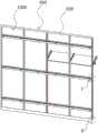
如图1至图13所示,本发明还提供一种衣帽间,包括:若干个安装于墙体700上的扣架800,并沿扣架800的长度方向设置有若干根立柱900,其中,相邻两根立柱900之间设置有装饰板1000,且上述所述的搁架可拆卸连接于立柱900上。As shown in FIG. 1 to FIG. 13 , the present invention also provides a cloakroom, comprising: a plurality of buckle frames 800 mounted on the
本发明提供的一种衣帽间,将墙体700上的装饰板1000与搁架集成设置,其中的装饰板1000不仅作为墙体700的装饰板1000,也可以作为搁架的封板,避免放置于搁架上的衣物与墙体700向碰触,使得整个衣帽间的结构更为简洁,另外,装饰板1000与扣件支架为可拆卸连接,搁架与立柱900之间为可拆卸连接,从而实现了安装的方便与快捷。In the cloakroom provided by the present invention, the
优选地,如图1至图13所示,沿立柱900的长度方向设置有两条条形凹槽910,其中,沿条形凹槽910的长度方向设置有若干个卡接块920。当搁架与立柱900相连接时,扣脚211直接卡接在立柱900的卡接块920上,安装方便,其中,相邻两个卡接块920之间的距离与相邻两个扣脚211之间的距离相匹配。Preferably, as shown in FIG. 1 to FIG. 13 , two strip-shaped
进一步优选地,扣架800包括若干个与墙体700安装的第一挂板810,且沿第一挂板810的侧壁向外斜向延伸形成第一支板811,其中,在第一挂板810与第一支板811之间形成第一滑槽812,与装饰板1000之间形成滑移扣接。Further preferably, the
在本实施例中,第一挂板810上设置有若干个安装孔813,一方面作为第一挂板810与墙体700之间的连接位置,另一方面作为调整相邻两块第一挂板810之间的平整度,从而使得悬挂于第一挂板810上的装饰板1000之间相互平行。In this embodiment, the
进一步优选地,装饰板1000包括门板1100,和连接于门板1100上的第二挂板1200,且沿第二挂板1200的侧壁向外斜向延伸形成第二支板1210,其中,第二挂板1200与第二支板1210之间形成第二滑槽1220。当扣架800与装饰板1000相连时,第二支板1210插入第一滑槽812内,第一支板811插入第二滑槽1220内,安装方便、可靠。Further preferably, the
进一步优选地,扣架800还包括一个托板820,其中,托板820的一侧通过垫块与墙体700相连,托板820的另一端设置有一个台阶821,作为立柱900的支撑部位。通过改变垫块的厚度,调整立柱900与墙体700之间的水平距离,提高装饰板1000表面的竖直平整度,进而提高搁架安装的平整度。Further preferably, the
进一步优选地,扣架800还包括一个顶板830,其中,顶板830插接于装饰板1000的顶部,使得相邻两个装饰板1000之间能够紧紧依靠,而不发生散架现象。Further preferably, the
本文中所描述的具体实施例仅仅是对本发明精神作举例说明。本发明所属技术领域的技术人员可以对所描述的具体实施例做各种各样的修改或补充或采用类似的方式替代,但并不会偏离本发明的精神或者超越所附权利要求书所定义的范围。The specific embodiments described herein are merely illustrative of the spirit of the invention. Those skilled in the art to which the present invention pertains can make various modifications or additions to the described specific embodiments or substitute in similar manners, but will not deviate from the spirit of the present invention or go beyond the definitions of the appended claims range.
Claims (10)
Translated fromChinesePriority Applications (1)
| Application Number | Priority Date | Filing Date | Title |
|---|---|---|---|
| CN201911017509.6ACN110859418A (en) | 2019-10-24 | 2019-10-24 | Shelf and cloakroom with suspension structure |
Applications Claiming Priority (1)
| Application Number | Priority Date | Filing Date | Title |
|---|---|---|---|
| CN201911017509.6ACN110859418A (en) | 2019-10-24 | 2019-10-24 | Shelf and cloakroom with suspension structure |
Publications (1)
| Publication Number | Publication Date |
|---|---|
| CN110859418Atrue CN110859418A (en) | 2020-03-06 |
Family
ID=69653234
Family Applications (1)
| Application Number | Title | Priority Date | Filing Date |
|---|---|---|---|
| CN201911017509.6APendingCN110859418A (en) | 2019-10-24 | 2019-10-24 | Shelf and cloakroom with suspension structure |
Country Status (1)
| Country | Link |
|---|---|
| CN (1) | CN110859418A (en) |
Citations (8)
| Publication number | Priority date | Publication date | Assignee | Title |
|---|---|---|---|---|
| US20090139943A1 (en)* | 2007-12-04 | 2009-06-04 | Clairson, Inc. | Standard and track shelving systems |
| CN202248976U (en)* | 2011-09-26 | 2012-05-30 | 深圳市中意集团有限公司 | Wall-attached coatroom |
| CN205094121U (en)* | 2015-06-19 | 2016-03-23 | 东莞家宝生活用品有限公司 | A wall-mounted shelf |
| CN105986436A (en)* | 2015-02-26 | 2016-10-05 | 王骏 | Anti-slip clothes airing rod |
| CN108049590A (en)* | 2017-12-30 | 2018-05-18 | 浙江亚厦装饰股份有限公司 | Modularization metope and trailing |
| CN208909397U (en)* | 2017-12-13 | 2019-05-31 | 厦门金牌厨柜股份有限公司 | A kind of hanging type hanging clothes hanger |
| CN208957176U (en)* | 2018-04-24 | 2019-06-11 | 广东宅可丽集成装配科技有限公司 | A kind of aluminium trim cabinet of convenient installation |
| CN211747900U (en)* | 2019-10-24 | 2020-10-27 | 宁波欧琳整体厨房有限公司 | Shelf and cloakroom with suspension structure |
- 2019
- 2019-10-24CNCN201911017509.6Apatent/CN110859418A/enactivePending
Patent Citations (8)
| Publication number | Priority date | Publication date | Assignee | Title |
|---|---|---|---|---|
| US20090139943A1 (en)* | 2007-12-04 | 2009-06-04 | Clairson, Inc. | Standard and track shelving systems |
| CN202248976U (en)* | 2011-09-26 | 2012-05-30 | 深圳市中意集团有限公司 | Wall-attached coatroom |
| CN105986436A (en)* | 2015-02-26 | 2016-10-05 | 王骏 | Anti-slip clothes airing rod |
| CN205094121U (en)* | 2015-06-19 | 2016-03-23 | 东莞家宝生活用品有限公司 | A wall-mounted shelf |
| CN208909397U (en)* | 2017-12-13 | 2019-05-31 | 厦门金牌厨柜股份有限公司 | A kind of hanging type hanging clothes hanger |
| CN108049590A (en)* | 2017-12-30 | 2018-05-18 | 浙江亚厦装饰股份有限公司 | Modularization metope and trailing |
| CN208957176U (en)* | 2018-04-24 | 2019-06-11 | 广东宅可丽集成装配科技有限公司 | A kind of aluminium trim cabinet of convenient installation |
| CN211747900U (en)* | 2019-10-24 | 2020-10-27 | 宁波欧琳整体厨房有限公司 | Shelf and cloakroom with suspension structure |
Similar Documents
| Publication | Publication Date | Title |
|---|---|---|
| TWI837164B (en) | Storage system, cantilivered bracket for storage system, cantilivered drawer assembly for storage system, cantilivered bracket for drawer assembly for storage system, panel installation method for wall mounted storage system, closet rod hanger system for storage system, and wall mounted shelving system | |
| US6837384B2 (en) | Storage track | |
| US3828937A (en) | Adjustable pole support system | |
| US6220186B1 (en) | Modular interior furnishing system | |
| US6315135B1 (en) | Combination shelving system | |
| CN104814607B (en) | Reassembling type wardrobe | |
| US9504323B1 (en) | Drawer slide structure | |
| US11224289B1 (en) | Shelf support assembly | |
| US20060091768A1 (en) | Adjustable door-mounted rack | |
| US20080197253A1 (en) | Standard | |
| US6044986A (en) | Wall mounted display fixture system | |
| KR101797641B1 (en) | display rack | |
| RU2140183C1 (en) | Furniture piece construction | |
| CN114760883B (en) | Elongated support members and cargo storage systems | |
| CN211747900U (en) | Shelf and cloakroom with suspension structure | |
| CN211748167U (en) | Shelf and cloakroom with hang function | |
| CN110859418A (en) | Shelf and cloakroom with suspension structure | |
| CN212015045U (en) | Shelf and cloakroom | |
| US4625471A (en) | Apparatus and method for supporting cupboards and the like | |
| CN113513873B (en) | a refrigerator | |
| CN211186772U (en) | Shelf and cloakroom | |
| CN110840123B (en) | Shelf and clothes and hat room | |
| CN211747899U (en) | Plane type shelf and clothes and hat room | |
| CN211722319U (en) | Flat plate type shelf and clothes and hat room | |
| CN110720814A (en) | A shelf and cloakroom |
Legal Events
| Date | Code | Title | Description |
|---|---|---|---|
| PB01 | Publication | ||
| PB01 | Publication | ||
| SE01 | Entry into force of request for substantive examination | ||
| SE01 | Entry into force of request for substantive examination |