CN110856671A - Shoulder joint prosthesis - Google Patents
Shoulder joint prosthesisDownload PDFInfo
- Publication number
- CN110856671A CN110856671ACN201810972039.8ACN201810972039ACN110856671ACN 110856671 ACN110856671 ACN 110856671ACN 201810972039 ACN201810972039 ACN 201810972039ACN 110856671 ACN110856671 ACN 110856671A
- Authority
- CN
- China
- Prior art keywords
- locking
- taper
- head
- starting point
- shoulder joint
- Prior art date
- Legal status (The legal status is an assumption and is not a legal conclusion. Google has not performed a legal analysis and makes no representation as to the accuracy of the status listed.)
- Granted
Links
Images


Classifications
- A—HUMAN NECESSITIES
- A61—MEDICAL OR VETERINARY SCIENCE; HYGIENE
- A61F—FILTERS IMPLANTABLE INTO BLOOD VESSELS; PROSTHESES; DEVICES PROVIDING PATENCY TO, OR PREVENTING COLLAPSING OF, TUBULAR STRUCTURES OF THE BODY, e.g. STENTS; ORTHOPAEDIC, NURSING OR CONTRACEPTIVE DEVICES; FOMENTATION; TREATMENT OR PROTECTION OF EYES OR EARS; BANDAGES, DRESSINGS OR ABSORBENT PADS; FIRST-AID KITS
- A61F2/00—Filters implantable into blood vessels; Prostheses, i.e. artificial substitutes or replacements for parts of the body; Appliances for connecting them with the body; Devices providing patency to, or preventing collapsing of, tubular structures of the body, e.g. stents
- A61F2/02—Prostheses implantable into the body
- A61F2/30—Joints
- A61F2/40—Joints for shoulders
- A61F2/4014—Humeral heads or necks; Connections of endoprosthetic heads or necks to endoprosthetic humeral shafts
- A—HUMAN NECESSITIES
- A61—MEDICAL OR VETERINARY SCIENCE; HYGIENE
- A61F—FILTERS IMPLANTABLE INTO BLOOD VESSELS; PROSTHESES; DEVICES PROVIDING PATENCY TO, OR PREVENTING COLLAPSING OF, TUBULAR STRUCTURES OF THE BODY, e.g. STENTS; ORTHOPAEDIC, NURSING OR CONTRACEPTIVE DEVICES; FOMENTATION; TREATMENT OR PROTECTION OF EYES OR EARS; BANDAGES, DRESSINGS OR ABSORBENT PADS; FIRST-AID KITS
- A61F2/00—Filters implantable into blood vessels; Prostheses, i.e. artificial substitutes or replacements for parts of the body; Appliances for connecting them with the body; Devices providing patency to, or preventing collapsing of, tubular structures of the body, e.g. stents
- A61F2/02—Prostheses implantable into the body
- A61F2/30—Joints
- A61F2/40—Joints for shoulders
- A61F2/4059—Humeral shafts
- A—HUMAN NECESSITIES
- A61—MEDICAL OR VETERINARY SCIENCE; HYGIENE
- A61F—FILTERS IMPLANTABLE INTO BLOOD VESSELS; PROSTHESES; DEVICES PROVIDING PATENCY TO, OR PREVENTING COLLAPSING OF, TUBULAR STRUCTURES OF THE BODY, e.g. STENTS; ORTHOPAEDIC, NURSING OR CONTRACEPTIVE DEVICES; FOMENTATION; TREATMENT OR PROTECTION OF EYES OR EARS; BANDAGES, DRESSINGS OR ABSORBENT PADS; FIRST-AID KITS
- A61F2/00—Filters implantable into blood vessels; Prostheses, i.e. artificial substitutes or replacements for parts of the body; Appliances for connecting them with the body; Devices providing patency to, or preventing collapsing of, tubular structures of the body, e.g. stents
- A61F2/02—Prostheses implantable into the body
- A61F2/30—Joints
- A61F2/40—Joints for shoulders
- A61F2/4014—Humeral heads or necks; Connections of endoprosthetic heads or necks to endoprosthetic humeral shafts
- A61F2002/4037—Connections of heads to necks
Landscapes
- Health & Medical Sciences (AREA)
- Orthopedic Medicine & Surgery (AREA)
- Cardiology (AREA)
- Oral & Maxillofacial Surgery (AREA)
- Transplantation (AREA)
- Engineering & Computer Science (AREA)
- Biomedical Technology (AREA)
- Heart & Thoracic Surgery (AREA)
- Vascular Medicine (AREA)
- Life Sciences & Earth Sciences (AREA)
- Animal Behavior & Ethology (AREA)
- General Health & Medical Sciences (AREA)
- Public Health (AREA)
- Veterinary Medicine (AREA)
- Prostheses (AREA)
Abstract
Translated fromChineseDescription
Translated fromChinese技术领域technical field
本发明涉及一种肩关节假体,特别涉及一种在反肩关节置换时使用的肩关节假体,其具有能够进行锥度连接、特别是莫氏锥度连接的肩胛盂托与肩胛盂头。The present invention relates to a shoulder joint prosthesis, in particular to a shoulder joint prosthesis used in reverse shoulder joint replacement.
背景技术Background technique
目前市场上主流的肩关节假体主要通过两种方式将肩胛盂头固定在肩胛盂托上,一种是由中央固定螺钉穿过肩胛盂头,再与肩胛盂托通过螺纹连接,锁紧肩胛盂头;另一种是通过锥度连接、特别是莫氏锥度连接,将肩胛盂头固定在肩胛盂托上。At present, the mainstream shoulder joint prostheses on the market mainly fix the glenoid head on the glenoid tray in two ways. One is to pass the central fixing screw through the glenoid head, and then connect it with the glenoid tray through threads to lock the scapula. The glenoid head; the other is to fix the glenoid head on the glenoid tray through a taper connection, especially a Morse taper connection.
中央螺钉连接方式是通过螺纹的锁紧将肩胛盂头固定在肩胛盂托上,其固定效果非常牢固,但由于肩胛盂头承载面上会增加一个螺钉孔,在运动时钉孔位置会与配合的肱骨衬垫部分产生摩擦,而此情况下的肱骨衬垫的磨损程度要远大于肩胛盂头没有钉孔的情况。The central screw connection method is to fix the glenoid head on the glenoid bracket through thread locking. The fixation effect is very firm, but since a screw hole will be added on the bearing surface of the glenoid head, the position of the screw hole will match during movement. The part of the humerus pad in the scapula produces friction, and the wear level of the humerus pad in this case is much greater than that in the case of the glenoid head without nail holes.
莫氏锥度连接方式能够避免在肩胛盂头的承载面增加螺钉孔,可以最大限度地降低肱骨衬垫的磨损,但是由于其是体内安装,在手术中进行装配时很难像体外安装时一样给莫氏锥度连接部分提供足够大的敲击力,将锥度配合部分锁得足够紧,而长时间在人体内,锥度配合部分会承受来自不同方向的力,其中必然会有一部分力可分解出沿锥度轴向方向向外的拔出力,作用范围位于肩胛盂头部分,这个拔出力可能造成反肩肩胛盂头的脱落。拔出力可以很大,一次性将锥度配合部分破坏,也可以很小,多次、反复作用,持续不断的使锥度配合部分产生松动。The Morse taper connection method can avoid adding screw holes on the bearing surface of the glenoid head, which can minimize the wear of the humerus pad, but because it is installed in the body, it is difficult to assemble it during surgery as it is installed outside the body. The Morse taper connection part provides a large enough percussion force to lock the taper fitting part tightly enough, and in the human body for a long time, the taper fitting part will bear forces from different directions, some of which must be decomposed along the edge. The pull-out force in the axial direction of the taper is located in the glenoid head. This pull-out force may cause the reverse glenoid head to fall off. The pull-out force can be very large, destroying the taper fitting part at one time, or it can be very small, repeatedly acting repeatedly, and continuously loosening the taper fitting part.
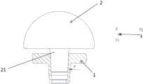
图1是现有技术中采用莫氏锥度连接的肩胛盂头和肩胛盂托的示意图。此种情况下,肩胛盂托1的内锥槽会给肩胛盂头2的锥形结构21一个斜向上的力F,F可分解为水平方向的压力F1和竖直方向的推力F2,其中推力F2沿中心轴方向向外,使肩胛盂头2更容易拔出。由于装配过程在人体内完成,肩胛盂不能承受较大敲击力,因此很难保证通过敲击力将锥度配合部分锁得足够紧;而肩胛盂头2与肩胛盂托1术后会长时间留在人体内,这种莫氏锥度连接部分会承受来自不同方向的力,其中必然会有一部分力可分解出沿莫氏锥度连接的纵向(轴向)方向向外的拔出力,作用范围位于肩胛盂头部分,这个拔出力可能造成肩胛盂头1的松动甚至脱落。而上述推力F2的存在无疑加剧了上述两方面风险。FIG. 1 is a schematic diagram of the glenoid head and the glenoid tray connected by Morse taper in the prior art. In this case, the inner conical groove of the
鉴于上述情况,业界急需一种新的肩关节假体,其具有能够进行锥度连接的肩胛盂托与肩胛盂头,该连接能够通过肩胛盂托与肩胛盂头上相互配合的辅助锁紧结构锁紧,从而避免肩胛盂头承载面因螺钉孔而对肱骨衬垫造成磨损,同时能够避免莫氏锥度连接在体内装配时因敲击力不够大而无法牢固固定以及莫氏锥度连接装配后在体内经受多次反复的拔出力作用而易于松动甚至脱落等问题。In view of the above-mentioned situation, the industry is in urgent need of a new shoulder joint prosthesis, which has a glenoid tray and a glenoid head that can be connected in a tapered manner, and the connection can be locked by an auxiliary locking structure that cooperates with the glenoid tray and the glenoid head. Therefore, the bearing surface of the glenoid head of the scapula is prevented from being worn on the humerus pad due to the screw hole, and at the same time, it can prevent the Morse taper connection from being firmly fixed due to insufficient knocking force when the Morse taper connection is assembled in the body, and the Morse taper connection in the body after assembly. It is easy to loosen or even fall off after being subjected to repeated pull-out forces.
发明内容SUMMARY OF THE INVENTION
本发明的一个目的在于提供一种肩关节假体,其具有能够进行锥度连接的肩胛盂托与肩胛盂头,该连接能够通过肩胛盂托与肩胛盂头上相互配合的辅助锁紧结构锁紧,以克服或改善上述现有技术中的至少一种缺陷。An object of the present invention is to provide a shoulder joint prosthesis, which has a scapula socket and a glenoid head that can be connected in a tapered manner, and the connection can be locked by an auxiliary locking structure that cooperates with the glenoid socket and the glenoid head. , in order to overcome or improve at least one of the above-mentioned defects in the prior art.
为实现上述目的,本发明提供一种肩关节假体,其包括肩胛盂托和肩胛盂头,其中:所述肩胛盂托具有杆部和位于杆部一端的底板,所述杆部和所述底板两者内设有一内锥槽,该内锥槽在从所述杆部朝向所述底板的方向上具有渐增的横截面直径,所述底板在与杆部相反的方向上具有锁紧部;所述肩胛盂头具有头部和柄部,所述柄部的远离所述头部的一端的至少一部分为锥形结构,所述锥形结构能与所述内锥槽锥度配合,所述柄部的靠近所述头部的一端上具有锁紧凸起。In order to achieve the above object, the present invention provides a shoulder joint prosthesis, which comprises a glenoid tray and a glenoid head, wherein: the glenoid tray has a rod portion and a bottom plate located at one end of the rod portion, the rod portion and the glenoid head are provided. An inner tapered groove is provided in both of the bottom plates, the inner tapered groove has an increasing cross-sectional diameter in the direction from the rod portion toward the bottom plate, and the bottom plate has a locking portion in the direction opposite to the rod portion The glenoid head of the scapula has a head and a handle, and at least a part of one end of the handle away from the head is a tapered structure, and the tapered structure can be taper-fitted with the inner tapered groove, and the A locking protrusion is provided on one end of the handle portion close to the head portion.
在一实施例中,所述锁紧部从所述肩胛盂托的所述底板远离所述杆部纵向延伸,并在其延伸末端处形成横向向内侧突出的卡止端,并且在所述锥形结构插入到所述内锥槽中并形成锥度连接的情况下,所述锁紧凸起能够被所述卡止端全部或部分地卡止保持于所述锁紧部内。In one embodiment, the locking portion extends longitudinally from the bottom plate of the glenoid tray away from the rod portion, and forms a latching end protruding laterally inwardly at the extending end thereof, and at the cone. When the shaped structure is inserted into the inner tapered groove and forms a taper connection, the locking protrusion can be locked and retained in the locking portion in whole or in part by the locking end.
在一实施例中,所述锁紧凸起包括与所述锥形结构的锥度方向基本同向的正向斜面以及与所述锥形结构的锥度方向反向的反向斜面,其中,所述正向斜面从正向斜面起点远离所述锥形结构延伸至所述锁紧凸起的最高点,其中所述正向斜面起点与所述锥形结构的大直径端处的锥部起点重合或位于所述锥部起点与所述头部之间,其中,所述反向斜面从所述锁紧凸起的最高点远离所述正向斜面起点延伸至反向斜面起点。In one embodiment, the locking protrusion includes a forward slope substantially in the same direction as the taper direction of the conical structure and a reverse slope opposite to the taper direction of the conical structure, wherein the A positive slope extends away from the tapered structure from a positive slope starting point, wherein the positive slope starting point coincides with a taper starting point at the large diameter end of the tapered structure to the highest point of the locking projection or located between the starting point of the taper portion and the head, wherein the reverse slope extends from the highest point of the locking protrusion away from the starting point of the forward slope to the starting point of the reverse slope.
在一实施例中,所述内锥槽的大直径端距所述卡止端的内侧端面的纵向高度大于所述锁紧凸起的最高点距所述锥形结构的锥部起点的纵向高度,且小于等于所述锥形结构的锥部起点距所述反向斜面起点的纵向高度,使所述卡止端能够卡置于所述反向斜面上。In one embodiment, the longitudinal height of the large-diameter end of the inner tapered groove from the inner end surface of the locking end is greater than the longitudinal height of the highest point of the locking protrusion from the starting point of the tapered portion of the tapered structure, and less than or equal to the longitudinal height of the starting point of the tapered portion of the tapered structure from the starting point of the reverse slope, so that the locking end can be locked on the reverse slope.
在一实施例中,所述锁紧凸起的最高点处的半径与所述反向斜面起点处的半径的差值大于0.1mm且小于1mm。In one embodiment, the difference between the radius at the highest point of the locking protrusion and the radius at the starting point of the reverse slope is greater than 0.1 mm and less than 1 mm.
在一实施例中,所述反向斜面的纵向高度大于1.4mm。In one embodiment, the longitudinal height of the reverse slope is greater than 1.4 mm.
在一实施例中,所述锁紧凸起的最高点处的直径大于所述锥形结构的锥部起点处的直径。In one embodiment, the diameter at the highest point of the locking protrusion is larger than the diameter at the starting point of the tapered portion of the tapered structure.
在一实施例中,所述锁紧部的内径大于等于所述锥形结构的锥部起点处的直径。In one embodiment, the inner diameter of the locking portion is greater than or equal to the diameter at the starting point of the tapered portion of the tapered structure.
在一实施例中,所述反向斜面的锥角大于所述正向斜面的锥角。In one embodiment, the taper angle of the reverse slope is greater than the taper angle of the forward slope.
在一实施例中,所述柄部从其与所述头部连接的部位到所述反向斜面起点之间呈圆柱状,该圆柱状的部分的直径大于所述锁紧部的内径φ,并且其中在所述正向斜面起点位于所述锥部起点与所述头部之间的情况下,所述锥形结构的锥部起点到正向斜面起点之间呈圆柱状或圆锥状。In one embodiment, the handle portion is cylindrical from the part where it is connected with the head to the starting point of the reverse slope, and the diameter of the cylindrical portion is larger than the inner diameter φ of the locking portion, In addition, when the starting point of the forward slope is located between the starting point of the taper portion and the head portion, the tapered structure is cylindrical or conical between the starting point of the taper portion and the starting point of the forward slope.
在一实施例中,所述锁紧部具有一个或多个沿纵向延伸的开口。In one embodiment, the locking portion has one or more longitudinally extending openings.
在一实施例中,所述锥形结构呈莫氏锥度。In one embodiment, the tapered structure has a Morse taper.
本发明的肩关节假体具有能够进行锥度连接的肩胛盂托与肩胛盂头,两者上具有相互配合的辅助锁紧结构,该锁紧结构是在锥度连接(特别是莫氏锥度连接)的基础上增加的、能够防止锥度连接松动的锁紧结构,本发明的肩关节假体具有以下有益技术效果中的至少其中之一:The shoulder joint prosthesis of the present invention has the glenoid tray and the glenoid head which can be connected with a taper, and the two have auxiliary locking structures that cooperate with each other. Based on the added locking structure that can prevent the taper connection from loosening, the shoulder joint prosthesis of the present invention has at least one of the following beneficial technical effects:
本发明的肩关节假体不存在螺纹连接所必须的螺钉孔,不会增大承载面对肱骨衬垫的磨损。The shoulder joint prosthesis of the present invention does not have screw holes necessary for threaded connection, and does not increase the wear of the humerus pad on the bearing face.
本发明的肩关节假体上的锁紧结构能够提供一个沿锥度轴向向内、持续作用的抗拔出力,此力可以增大肩胛盂头装配时的敲击力,使装配更加牢固。The locking structure on the shoulder joint prosthesis of the present invention can provide an anti-pull-out force acting inwardly and continuously along the taper axis, which can increase the knocking force when the glenoid head is assembled and make the assembly more firm.
本发明的肩关节假体上的锁紧结构所提供的抗拔出力可以优先抵消部分肩胛盂头受到的、轴向向外的拔出力,保护莫氏锥度连接,降低肩胛盂头松动、脱落的风险。The anti-pull-out force provided by the locking structure on the shoulder joint prosthesis of the present invention can preferentially offset the axially outward pull-out force received by part of the glenoid head, protect the Morse taper connection, reduce the loosening of the glenoid head, reduce Risk of falling off.
本发明的肩关节假体上的辅助锁紧结构是一个弹性结构,其在完全失效前有自动回弹能力,相对于锥度部分的单一方向失效的不可逆性,辅助锁紧结构在承受较小力的反复拔出力时具有明显的优势,而其失效的情况只出现在锥度配合完全失效之后,在锥度配合失效前会持续的保持增强锥度配合的稳定性。The auxiliary locking structure on the shoulder joint prosthesis of the present invention is an elastic structure, which has the ability to automatically rebound before it completely fails. Compared with the irreversibility of the single-direction failure of the tapered part, the auxiliary locking structure can withstand less force. It has obvious advantages in repeated pull-out force, and its failure only occurs after the taper fit completely fails, and the stability of the enhanced taper fit will continue to be maintained before the taper fit fails.
附图说明Description of drawings
通过结合附图考虑以下对本发明的优选实施例的详细说明,本发明的各种目的、特征和优点将变得更加显而易见。附图仅为本发明的示例性图示,并非一定是按比例绘制。在附图中,同样的附图标记始终表示相同或类似的部件。其中:Various objects, features and advantages of the present invention will become more apparent from consideration of the following detailed description of the preferred embodiments of the present invention in conjunction with the accompanying drawings. The drawings are merely exemplary illustrations of the invention and are not necessarily drawn to scale. Throughout the drawings, the same reference numbers refer to the same or like parts. in:
图1是现有技术中采用莫氏锥度连接的肩胛盂头和肩胛盂托的示意图。FIG. 1 is a schematic diagram of the glenoid head and the glenoid tray connected by Morse taper in the prior art.
图2是根据本发明实施例的具有锁紧部的肩胛盂托的立体示意图。FIG. 2 is a schematic perspective view of a glenoid tray with a locking portion according to an embodiment of the present invention.
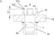
图3是根据本发明实施例的具有锁紧部的肩胛盂托的剖视图。3 is a cross-sectional view of a glenoid tray with a locking portion according to an embodiment of the present invention.
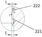
图4是根据本发明实施例的具有锁紧凸起的肩胛盂头的剖视图。4 is a cross-sectional view of the glenoid head with locking projections according to an embodiment of the present invention.
图5是图4中I部分的放大视图。FIG. 5 is an enlarged view of part I in FIG. 4 .
图6是图3所示的肩胛盂托与图4所示的肩胛盂头连接在一起后的剖视图。FIG. 6 is a cross-sectional view of the glenoid tray shown in FIG. 3 and the glenoid head shown in FIG. 4 after being connected together.
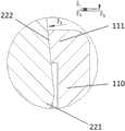
图7是图6中II部分的放大视图。FIG. 7 is an enlarged view of part II in FIG. 6 .
附图标记说明:Description of reference numbers:
1 肩胛盂托1 glenoid rest
11 锁紧部11 Locking part
110 锁紧壁110 Locking wall
111 卡止端111 Locking end
112 开口112 Openings
113 内侧端面113 Inner end face
12 底板12 Bottom plate
13 杆部13 rod
14 内锥槽14 Inner taper groove
2 肩胛盂头2 glenoid head
20 头部20 head
205 环槽205 Ring groove
21 锥形结构21 Conical structure
22 锁紧凸起22 Locking projection
221 正向斜面221 Positive slope
222 反向斜面222 Reverse Bevel
29 柄部29 handle
F、F1、F2 力F, F1, F2 force
Fa、Fb、Fc 力Fa, Fb, Fc force
α 莫氏锥度锥角α Morse taper taper angle

θ1、θ2 锥角θ1, θ2 cone angle
h1、h2、h3 纵向高度h1, h2, h3 vertical height
A、B 距离A and B distance
M 锥部起点M Taper start point
N 正向斜面起点N Positive slope start point
O 反向斜面起点O Reverse slope start point
P 锁紧凸起的最高点P Highest point of locking projection
具体实施方式Detailed ways
下面结合附图对本发明作进一步的详细说明。The present invention will be further described in detail below in conjunction with the accompanying drawings.
图2是根据本发明实施例的具有锁紧部的肩胛盂托的立体示意图。图3是根据本发明实施例的具有锁紧部的肩胛盂托的剖视图。图4是根据本发明实施例的具有锁紧凸起的肩胛盂头的剖视图。在本发明的一实施例中,肩关节假体包括肩胛盂托1和肩胛盂头2。FIG. 2 is a schematic perspective view of a glenoid tray with a locking portion according to an embodiment of the present invention. 3 is a cross-sectional view of a glenoid tray with a locking portion according to an embodiment of the present invention. 4 is a cross-sectional view of the glenoid head with locking projections according to an embodiment of the present invention. In an embodiment of the present invention, the shoulder joint prosthesis includes a
参照图2和图3,在本发明的一实施例中,肩胛盂托1包括近似筒状的杆部13和位于杆部13一端外围的底板12,在杆部13和底板12两者内设有一内锥槽14。该内锥槽14在从杆部13朝向底板12的方向(图3中为向上的方向)上具有渐增的横截面直径。底板12在与杆部相反的方向上具有锁紧部11。底板12沿与肩胛盂托1的纵向方向(即,杆部13的纵向方向)垂直的径向方向向外突出于杆部13,也突出于锁紧部11。该底板12可以为圆环形或其他任何合适的形状。2 and 3 , in an embodiment of the present invention, the
在一实施例中,内锥槽14呈莫氏锥度。In one embodiment, the inner tapered
图4示意性示出了肩胛盂头2,其具有头部20和柄部29。柄部29的远离头部20的一端(图4中为下端)的至少一部分为锥形结构21。该锥形结构21可与肩胛盂托1中的内锥槽14锥度配合,从而实现肩胛盂头2与肩胛盂托1之间所需的连接。柄部29的靠近头部20的一端上具有锁紧凸起22。FIG. 4 schematically shows the
在一实施例中,锥形结构21呈莫氏锥度。此时,锥形结构21与内锥槽14实现莫氏锥度配合,从而实现肩胛盂头2与肩胛盂托1之间的莫氏锥度连接。In one embodiment, the tapered
位于肩胛盂托1上的锁紧部11和位于肩胛盂头2上的锁紧凸起22相互配合,用于辅助肩胛盂托1与肩胛盂头2之间的锥度连接。The locking
锁紧部11包括从底板12沿竖直方向与杆部13相对地(图中所示为竖直向上的方向)延伸出的锁紧壁110。该锁紧壁110围成环形,且在其末端具有向内侧突出的卡止端111。具体而言,锁紧部11从肩胛盂托1的内锥槽14具有较大直径的端部处向外纵向延伸,并在其延伸末端处形成横向向内侧突出的卡止端111。The locking
继续如图4所示,在本发明的一实施例中,锁紧凸起22位于柄部29上方,具体地在锥形结构21的大直径端处的锥部起点M与该肩胛盂头2的头部20之间。在锥形结构21插入到内锥槽14中并形成锥度连接的情况下,锁紧凸起22可被卡止端111全部或部分地卡止保持于锁紧部11内。Continuing as shown in FIG. 4 , in an embodiment of the present invention, the locking
肩胛盂头2的头部20例如为近似半球形,其内侧具有围绕柄部29的向内凹陷的环槽205。该环槽205的外周壁在纵向上覆盖锁紧凸起22。亦即,环槽205的外径小于头部20的外径,但大于锁紧部11的外径,从而在肩胛盂头2与肩胛盂托1之间形成锥度连接时,锁紧部11能够被容纳在环槽205中。锥形结构21具有与内锥槽14相对应的锥度,以便其插入内锥槽14内形成锥度连接。在一实施例中,该锥度为莫氏锥度。The
锁紧凸起22包括与锥形结构21的锥度方向基本同向的正向斜面221以及与锥形结构21的锥度方向反向的反向斜面222。The locking
其中,锥形结构21在锥部起点M与头部20之间具有一正向斜面起点N,正向斜面221从该正向斜面起点N远离锥部起点M延伸至锁紧凸起22的最高点P,而反向斜面222从锁紧凸起22的最高点P远离正向斜面起点N延伸至一反向斜面起点O,换句话说,反向斜面222从图4中所示的反向斜面起点O延伸至最高点P,从而使得卡止端111能够卡置于反向斜面222上。其中,如图4所示,正向斜面起点N位于锥部起点M与头部20之间。柄部29上的正向斜面起点N与锥部起点M之间(即锁紧凸起22与锥形结构21之间)为具有适当直径的柱形或锥形等。The tapered
在另一实施例中,正向斜面起点N也可与锥形结构21的大直径端处的锥部起点M重合(图中未示出),即锁紧凸起22与锥形结构21紧邻。In another embodiment, the starting point N of the positive slope can also coincide with the starting point M of the taper portion at the large diameter end of the tapered structure 21 (not shown in the figure), that is, the locking
图6是图3所示的肩胛盂托与图4所示的肩胛盂头连接在一起后的剖视图。FIG. 6 is a cross-sectional view of the glenoid tray shown in FIG. 3 and the glenoid head shown in FIG. 4 after being connected together.
在反肩关节置换时,一般会先将肩胛盂托装在肩胛盂上,再通过锥度连接(特别地,莫氏锥度连接)将肩胛盂头装配在肩胛盂托上。In reverse shoulder joint replacement, the glenoid tray is generally installed on the glenoid first, and then the glenoid head is assembled on the glenoid tray through a taper connection (in particular, Morse taper connection).
如图6所示,在本发明的一实施例中,将肩胛盂头2的锥形结构21插入肩胛盂托1的内锥槽14中,并通过敲击形成莫氏锥度连接。一般而言,锥形结构21与内锥槽14之间的莫氏锥度连接为刚性连接。锁紧部11的锁紧壁110的卡止端111沿着锁紧凸起22滑动、越过锁紧凸起22的最高点并卡在锁紧凸起22上方的反向斜面222上。其中,锁紧部11与锁紧凸起22相互配合,以防止肩胛盂头和肩胛盂托之间的锥度连接松动,两者可以合称为辅助锁紧结构。As shown in FIG. 6, in an embodiment of the present invention, the
在一实施例中,锁紧部11设置有一个或多个沿纵向延伸的开口112,使锁紧部11形成弹性结构,以利于锁紧壁110的卡止端111越过锁紧凸起22的最高点,并实现弹性卡合。当然,开口112的数量在本发明中并无限制,可以根据情况设置不同数量的开口112。开口优选地可具有上宽下窄的形状,以在不减小其弹性的基础上尽可能增加卡止端可拓宽的程度。另外,开口112可以设计为各种形状,例如,竖直狭槽加倒圆形(如图所示)、圆角矩形等,而不受限于发明所述以及所示。In one embodiment, the locking
如图7所示,在莫氏锥度连接的上方,根据本发明实施例的锁紧部11施加一个持续的力Fa,该力可分解为水平方向的压力Fc和沿轴向方向向下的抗拔出力Fb。该抗拔出力Fb与敲击力方向相同,相对地增大了敲击力,使得在手术中锥度配合部分能够被锁得足够紧;同时,在手术后,该抗拔出力Fb持续发挥作用,抵消诸如F2的拔出力,使得肩胛盂头长期牢固固定。在一实施例中,锁紧部施加在锁紧凸起上的抗拔出力Fb可在50N-500N之间。As shown in FIG. 7 , above the Morse taper connection, the locking
需注意的是,在敲击过程中,锁紧部11的锁紧壁110的卡止端111先一步到达反向斜面222上,随后莫氏锥度连接锁紧,辅助锁紧结构进入锁紧状态,而通过锁紧凸起22的最高点时的最大敲击力,仍要远远小于莫氏锥度连接锁紧所需的敲击力。由此,卡止端111可以顺利越过锁紧凸起22的最高点,并最终卡在反向斜面222上。It should be noted that during the knocking process, the locking
图5是图4中I部分的放大视图。图7是图6中II部分的放大视图。下面参照图3-图7描述本发明一实施例的肩关节假体。FIG. 5 is an enlarged view of part I in FIG. 4 . FIG. 7 is an enlarged view of part II in FIG. 6 . Next, a shoulder joint prosthesis according to an embodiment of the present invention will be described with reference to FIGS. 3-7 .
如图4、图5所示,图中的距离B为锁紧凸起22的最高点P处的半径与正向斜面起点N处的半径的差值,距离A为锁紧凸起22的最高点P处的半径与反向斜面222的反向斜面起点O处的半径的差值。显然,距离A、距离B大于0。在一实施例中,B为0.475mm。As shown in FIG. 4 and FIG. 5 , the distance B in the figures is the difference between the radius at the highest point P of the locking
为保证装配过程中,锁紧部在逐渐通过锁紧凸起时承受不大的阻力,锁紧凸起22的最高点P处的半径与反向斜面起点O处的半径的差值A优选地大于0.1mm且小于1mm。在一实施例中,A为0.3mm。In order to ensure that during the assembly process, the locking portion bears little resistance when gradually passing through the locking protrusion, the difference A between the radius at the highest point P of the locking
锥形结构21的锥部起点M处的直径D为锥形结构21上与肩胛盂托1的内锥槽14配合的锥部的最大直径。该直径D可以根据实际需求决定。在一实施例中,该直径D为8.45mm。The diameter D at the starting point M of the tapered portion of the tapered
由此,由于在图4-图5所示的实施例中,锁紧凸起22与锥形结构21之间为具有直径D的柱形,因此,锁紧凸起22的最高点P处的直径为D+2B,显然大于锥形结构21的大直径端处的直径D。Therefore, in the embodiment shown in FIGS. 4-5 , the space between the locking
锁紧部11的内径

在本发明的实施例中,锥形结构21在反向斜面起点O处的直径C大于锁紧部11的内径φ,从而保证锁紧部具有持续的弹力。优选地,在柄部29上,从该柄部与头部20连接的部位到反向斜面起点O之间的部分呈具有直径C的圆柱状。In the embodiment of the present invention, the diameter C of the tapered
参照图3-图5,内锥槽14的大直径端距卡止端111的内侧端面113的纵向高度h3大于等于锁紧凸起22的最高点P距离锥形结构21的锥部起点M处的纵向高度h2,以使卡止端111能够卡止在反向斜面222上。在一实施例中,h3为4.5mm。在一实施例中,h2为2mm。3 to 5 , the longitudinal height h3 of the large diameter end of the inner tapered
由于莫氏锥度的锥角α的公差为±0°2’30”,为保证辅助锁紧结构正好落在反向斜面上,优选地,反向斜面222的纵向高度h1(锁紧凸起22的最高点P距离反向斜面起点O的高度)大于1.4mm。在距离A相同的情况下,h1越小,反斜面角度越大,辅助锁紧结构提供的轴向抗拔出力越大,因此,优选地,h1取值在大于1.4mm的基础上尽可能小,例如,h1可为1.41mm。在距离B相同的情况下h2越大,锁紧部11在通过正斜面的时候越平缓,也就越容易通过,但是h2必须小于等于与其配合的内锥上方的h3的高度,即h2≤h3。同样,为保证卡止端111正好落在反向斜面上,纵向高度h2与纵向高度h1之和可以大于等于纵向高度h3。Since the tolerance of the taper angle α of the Morse taper is ±0°2'30", in order to ensure that the auxiliary locking structure just falls on the reverse slope, preferably, the longitudinal height h1 of the reverse slope 222 (the locking
另外,如图5所示,将反向斜面起点O与正向斜面起点N用一直线(虚线)连接,在本文中,将反向斜面222与该直线形成的角度θ1称为反向斜面的锥角,而将正向斜面221与该直线形成的角度θ2称为正向斜面的锥角,在本实施例中,反向斜面的锥角大于正向斜面的锥角,以利于锁紧凸起22容易进入锁紧部11中被卡止端111卡止,而不容易从锁紧部11中拔出。优选地,反向斜面222的锥角θ1为12.1°。优选地,正向斜面221的锥角θ2为10°左右。In addition, as shown in FIG. 5 , the starting point O of the reverse slope and the starting point N of the forward slope are connected by a straight line (dotted line). The angle θ2 formed by the
在反向肩关节置换过程中,一般会先将肩胛盂托装在肩胛盂上,再通过锥度配合将肩胛盂头装配在肩胛盂托上,由于装配过程在人体内完成,很难保证通过敲击力将锥度配合部分锁足够紧,此时辅助锁紧装置可以提供一个额外的、沿轴向方向持续向内的力,叠加后相对增大敲击力,使锥度配合部分锁紧。需要说明的是,在敲击过程中,锥度配合上部的锁紧结构先一步到达位置并进入辅助锁紧状态,而通过凸起位置时的最大敲击力,要远远小于锥度锁紧所需的敲击力。In the process of reverse shoulder arthroplasty, the glenoid bracket is usually first installed on the scapula, and then the glenoid head is assembled on the glenoid through the taper fit. Since the assembly process is completed in the human body, it is difficult to ensure that the The striking force locks the taper fitting part tightly enough. At this time, the auxiliary locking device can provide an additional, continuous inward force along the axial direction. After superposition, the striking force is relatively increased to lock the taper fitting part. It should be noted that during the tapping process, the taper cooperates with the upper locking structure to reach the position first and enter the auxiliary locking state, and the maximum tapping force when passing through the convex position is much smaller than the taper locking required. percussion force.
在根据本发明实施例的肩关节假体中的肩胛盂托与肩胛盂头完成莫氏锥度连接之后,术后长时间在人体内,莫氏锥度连接部分会承受来自不同方向的力,其中必然会有一部分力可分解出沿莫氏锥度连接的轴向方向向外的拔出力,作用范围位于肩胛盂头部分,这个拔出力可能造成肩胛盂头的脱落。上述的拔出力可能很大,能够一次性将锥度连接部分破坏,也可能很小,通过多次、反复作用,持续不断的使莫氏锥度连接部分产生松动。拔出力作用在肩胛盂头部分,而辅助锁紧结构又位于莫氏锥度连接部分的上方,会优先于莫氏锥度连接部分承受拔出力。如果拔出力很大,辅助锁紧结构可抵消一部分沿莫氏锥度连接轴向方向向外的拔出力,降低莫氏锥度连接部分失效的风险;如果拔出力很小,其必然将降低甚至抵消拔出力,大大降低莫氏锥度连接部分松动的风险。需要说明的是,辅助锁紧结构是一个弹性结构,其在完全失效前是有自动回弹的能力,相对于莫氏锥度连接的单一方向失效的不可逆性,辅助锁紧结构在承受较小力的反复拔出力时具有明显的优势,而其失效的情况只出现在莫氏锥度连接完全失效之后,在莫氏锥度连接失效前会持续的保持增强莫氏锥度连接的稳定性。After the Morse taper connection is completed between the glenoid tray and the glenoid head in the shoulder joint prosthesis according to the embodiment of the present invention, the Morse taper connection part will be subjected to forces from different directions in the human body for a long time after the operation. There will be a part of the force that can be decomposed into the pull-out force along the axial direction of the Morse taper connection, and the scope of action is in the glenoid head part. This pull-out force may cause the glenoid head to fall off. The above-mentioned pull-out force may be very large, which can destroy the taper connection part at one time, or it may be very small, and through repeated actions, the Morse taper connection part will be loosened continuously. The pull-out force acts on the glenoid head part of the scapula, and the auxiliary locking structure is located above the Morse taper connection part, which will bear the pull-out force in preference to the Morse taper connection part. If the pull-out force is large, the auxiliary locking structure can offset part of the pull-out force outward along the axial direction of the Morse taper connection, reducing the risk of failure of the Morse taper connection part; if the pull-out force is small, it will inevitably reduce the It even counteracts the pull-out force, greatly reducing the risk of loosening the Morse taper connection part. It should be noted that the auxiliary locking structure is an elastic structure, which has the ability to automatically rebound before it completely fails. Compared with the irreversibility of Morse taper connection failure in one direction, the auxiliary locking structure can withstand less force. It has obvious advantages in repeated pull-out force, and its failure only occurs after the Morse taper connection fails completely, and the stability of the Morse taper connection will continue to be enhanced before the Morse taper connection fails.
应理解的是,尽管上文示出并描述了优选实施例,但是发明并不限于上述具体实施例,在不背离所附权利要求书的精神和范围的情况下,本领域技术人员可进行各种修改和变形。因此,应注意的是,各种修改和变形不能被认为超出发明的技术精神和范围。It should be understood that while preferred embodiments have been shown and described above, the invention is not limited to the specific embodiments described above, and that those skilled in the art can make various Modifications and deformations. Therefore, it should be noted that various modifications and variations cannot be considered beyond the technical spirit and scope of the invention.
Claims (12)


Priority Applications (1)
| Application Number | Priority Date | Filing Date | Title |
|---|---|---|---|
| CN201810972039.8ACN110856671B (en) | 2018-08-24 | 2018-08-24 | Shoulder Prosthesis |
Applications Claiming Priority (1)
| Application Number | Priority Date | Filing Date | Title |
|---|---|---|---|
| CN201810972039.8ACN110856671B (en) | 2018-08-24 | 2018-08-24 | Shoulder Prosthesis |
Publications (2)
| Publication Number | Publication Date |
|---|---|
| CN110856671Atrue CN110856671A (en) | 2020-03-03 |
| CN110856671B CN110856671B (en) | 2025-06-20 |
Family
ID=69635435
Family Applications (1)
| Application Number | Title | Priority Date | Filing Date |
|---|---|---|---|
| CN201810972039.8AActiveCN110856671B (en) | 2018-08-24 | 2018-08-24 | Shoulder Prosthesis |
Country Status (1)
| Country | Link |
|---|---|
| CN (1) | CN110856671B (en) |
Cited By (1)
| Publication number | Priority date | Publication date | Assignee | Title |
|---|---|---|---|---|
| WO2021196748A1 (en)* | 2020-03-30 | 2021-10-07 | 北京市春立正达医疗器械股份有限公司 | Glenoid prosthesis applied in total shoulder arthroplasty |
Citations (9)
| Publication number | Priority date | Publication date | Assignee | Title |
|---|---|---|---|---|
| US4135517A (en)* | 1977-07-21 | 1979-01-23 | Minnesota Mining And Manufacturing Company | Femoral prosthesis trial fitting device |
| US4865605A (en)* | 1988-02-02 | 1989-09-12 | Dines David M | Modular shoulder prosthesis |
| CN201208317Y (en)* | 2008-03-17 | 2009-03-18 | 常州好利医疗器械有限公司 | Double acting head structure in artificial hip joint system |
| US20100249934A1 (en)* | 2007-01-08 | 2010-09-30 | Warsaw Orthopedic, Inc. | Ratcheting Expandable Corpectomy/Vertebrectomy Cage |
| CN201668540U (en)* | 2010-04-20 | 2010-12-15 | 北京百慕航材高科技股份有限公司 | Biological fixed double-equator anti-dislocation acetabulum prosthesis |
| CN102458311A (en)* | 2009-05-07 | 2012-05-16 | 史密夫和内修有限公司 | Modular trial heads for a prosthetic |
| CN104665960A (en)* | 2015-02-15 | 2015-06-03 | 张洋 | Orthopedic prosthesis for proximal radioulnar joint fusion |
| US20190159905A1 (en)* | 2016-04-11 | 2019-05-30 | Cossington Limited | Modular spacer device |
| CN209236468U (en)* | 2018-08-24 | 2019-08-13 | 北京纳通医学科技研究院有限公司 | Shoulder joint prosthesis |
- 2018
- 2018-08-24CNCN201810972039.8Apatent/CN110856671B/enactiveActive
Patent Citations (9)
| Publication number | Priority date | Publication date | Assignee | Title |
|---|---|---|---|---|
| US4135517A (en)* | 1977-07-21 | 1979-01-23 | Minnesota Mining And Manufacturing Company | Femoral prosthesis trial fitting device |
| US4865605A (en)* | 1988-02-02 | 1989-09-12 | Dines David M | Modular shoulder prosthesis |
| US20100249934A1 (en)* | 2007-01-08 | 2010-09-30 | Warsaw Orthopedic, Inc. | Ratcheting Expandable Corpectomy/Vertebrectomy Cage |
| CN201208317Y (en)* | 2008-03-17 | 2009-03-18 | 常州好利医疗器械有限公司 | Double acting head structure in artificial hip joint system |
| CN102458311A (en)* | 2009-05-07 | 2012-05-16 | 史密夫和内修有限公司 | Modular trial heads for a prosthetic |
| CN201668540U (en)* | 2010-04-20 | 2010-12-15 | 北京百慕航材高科技股份有限公司 | Biological fixed double-equator anti-dislocation acetabulum prosthesis |
| CN104665960A (en)* | 2015-02-15 | 2015-06-03 | 张洋 | Orthopedic prosthesis for proximal radioulnar joint fusion |
| US20190159905A1 (en)* | 2016-04-11 | 2019-05-30 | Cossington Limited | Modular spacer device |
| CN209236468U (en)* | 2018-08-24 | 2019-08-13 | 北京纳通医学科技研究院有限公司 | Shoulder joint prosthesis |
Cited By (1)
| Publication number | Priority date | Publication date | Assignee | Title |
|---|---|---|---|---|
| WO2021196748A1 (en)* | 2020-03-30 | 2021-10-07 | 北京市春立正达医疗器械股份有限公司 | Glenoid prosthesis applied in total shoulder arthroplasty |
Also Published As
| Publication number | Publication date |
|---|---|
| CN110856671B (en) | 2025-06-20 |
Similar Documents
| Publication | Publication Date | Title |
|---|---|---|
| US11259931B2 (en) | Glenoid anchor for a shoulder joint prosthesis | |
| US9463057B2 (en) | Orthopedic fastener | |
| JP6182139B2 (en) | Acetabular connection fixing screw and a composite structure of the acetabular connection fixing screw and an acetabular cup of an artificial hip joint | |
| JP5622387B2 (en) | Receiving part for receiving the rod and connecting it to the bone anchoring element, and a bone anchoring device having such a receiving part | |
| US20080045969A1 (en) | Extractor for a bone connection element | |
| US20160270922A1 (en) | Glenoid Anchor for a Shoulder Joint Prosthesis | |
| US20170020573A1 (en) | Pedicle screw tulip assembly with multi-segmented member | |
| US9155632B2 (en) | Orthopedic instrument, system and method for implanting an acetabular cup | |
| JP2012520100A (en) | Spine implant with lockable ball joint connection | |
| CN103445846B (en) | Polyaxial bone anchoring device | |
| JP6768076B2 (en) | Bone fixation device | |
| RU2011143386A (en) | CUTTING HEAD CONTAINING A TAIL WITH A DROP AND A CUTTING TOOL CONTAINING SUCH A CUTTING HEAD | |
| JP6285554B2 (en) | Mounting and connecting members for thumb carpal metacarpal joint prosthesis, and thumb carpal metacarpal joint prosthesis | |
| JP2018110842A (en) | Modular bone plate and member of such modular bone plate | |
| CN110856671A (en) | Shoulder joint prosthesis | |
| JP2018523537A (en) | Sinking and removable elastic coupling implant system | |
| KR101239512B1 (en) | Bone Fixation Means | |
| KR101178488B1 (en) | Apparatus for bone fixation | |
| CN209236468U (en) | Shoulder joint prosthesis | |
| CN112353474A (en) | A universal pedicle screw | |
| KR200410476Y1 (en) | Pedicle screw | |
| JP7137814B2 (en) | Mounting device | |
| US11174888B2 (en) | Threaded pin | |
| CN102835996B (en) | Lockpin type central nail device | |
| CN201719366U (en) | bone fixation device |
Legal Events
| Date | Code | Title | Description |
|---|---|---|---|
| PB01 | Publication | ||
| PB01 | Publication | ||
| SE01 | Entry into force of request for substantive examination | ||
| SE01 | Entry into force of request for substantive examination | ||
| CB02 | Change of applicant information | Address after:G356, 3rd floor, building 1, yard 9, CHENGWAN street, Haidian District, Beijing 100094 Applicant after:Beijing natong Medical Technology Holding Co.,Ltd. Applicant after:BEIJING NATON TECHNOLOGY GROUP Co.,Ltd. Address before:100095 3, 2 floor, 2 building, 103 Beiqing Road, Haidian District, Beijing. Applicant before:BEIJING NATON INSTITUTE OF MEDICAL TECHNOLOGY Co.,Ltd. Applicant before:BEIJING NATON TECHNOLOGY GROUP Co.,Ltd. | |
| CB02 | Change of applicant information | ||
| TA01 | Transfer of patent application right | Effective date of registration:20210319 Address after:G356, 3rd floor, building 1, yard 9, CHENGWAN street, Haidian District, Beijing 100094 Applicant after:Beijing natong Medical Technology Holding Co.,Ltd. Address before:G356, 3rd floor, building 1, yard 9, CHENGWAN street, Haidian District, Beijing 100094 Applicant before:Beijing natong Medical Technology Holding Co.,Ltd. Applicant before:BEIJING NATON TECHNOLOGY GROUP Co.,Ltd. | |
| TA01 | Transfer of patent application right | ||
| GR01 | Patent grant | ||
| GR01 | Patent grant |