CN110854602A - A multi-purpose mating multi-cavity rectangular modular connector - Google Patents
A multi-purpose mating multi-cavity rectangular modular connectorDownload PDFInfo
- Publication number
- CN110854602A CN110854602ACN201911167497.5ACN201911167497ACN110854602ACN 110854602 ACN110854602 ACN 110854602ACN 201911167497 ACN201911167497 ACN 201911167497ACN 110854602 ACN110854602 ACN 110854602A
- Authority
- CN
- China
- Prior art keywords
- cavity
- plug
- socket
- sockets
- locking
- Prior art date
- Legal status (The legal status is an assumption and is not a legal conclusion. Google has not performed a legal analysis and makes no representation as to the accuracy of the status listed.)
- Granted
Links
Images


Classifications
- H—ELECTRICITY
- H01—ELECTRIC ELEMENTS
- H01R—ELECTRICALLY-CONDUCTIVE CONNECTIONS; STRUCTURAL ASSOCIATIONS OF A PLURALITY OF MUTUALLY-INSULATED ELECTRICAL CONNECTING ELEMENTS; COUPLING DEVICES; CURRENT COLLECTORS
- H01R27/00—Coupling parts adapted for co-operation with two or more dissimilar counterparts
- H—ELECTRICITY
- H01—ELECTRIC ELEMENTS
- H01R—ELECTRICALLY-CONDUCTIVE CONNECTIONS; STRUCTURAL ASSOCIATIONS OF A PLURALITY OF MUTUALLY-INSULATED ELECTRICAL CONNECTING ELEMENTS; COUPLING DEVICES; CURRENT COLLECTORS
- H01R13/00—Details of coupling devices of the kinds covered by groups H01R12/70 or H01R24/00 - H01R33/00
- H01R13/46—Bases; Cases
- H01R13/502—Bases; Cases composed of different pieces
- H—ELECTRICITY
- H01—ELECTRIC ELEMENTS
- H01R—ELECTRICALLY-CONDUCTIVE CONNECTIONS; STRUCTURAL ASSOCIATIONS OF A PLURALITY OF MUTUALLY-INSULATED ELECTRICAL CONNECTING ELEMENTS; COUPLING DEVICES; CURRENT COLLECTORS
- H01R13/00—Details of coupling devices of the kinds covered by groups H01R12/70 or H01R24/00 - H01R33/00
- H01R13/62—Means for facilitating engagement or disengagement of coupling parts or for holding them in engagement
- H01R13/627—Snap or like fastening
- H—ELECTRICITY
- H01—ELECTRIC ELEMENTS
- H01R—ELECTRICALLY-CONDUCTIVE CONNECTIONS; STRUCTURAL ASSOCIATIONS OF A PLURALITY OF MUTUALLY-INSULATED ELECTRICAL CONNECTING ELEMENTS; COUPLING DEVICES; CURRENT COLLECTORS
- H01R13/00—Details of coupling devices of the kinds covered by groups H01R12/70 or H01R24/00 - H01R33/00
- H01R13/62—Means for facilitating engagement or disengagement of coupling parts or for holding them in engagement
- H01R13/629—Additional means for facilitating engagement or disengagement of coupling parts, e.g. aligning or guiding means, levers, gas pressure electrical locking indicators, manufacturing tolerances
- H—ELECTRICITY
- H01—ELECTRIC ELEMENTS
- H01R—ELECTRICALLY-CONDUCTIVE CONNECTIONS; STRUCTURAL ASSOCIATIONS OF A PLURALITY OF MUTUALLY-INSULATED ELECTRICAL CONNECTING ELEMENTS; COUPLING DEVICES; CURRENT COLLECTORS
- H01R13/00—Details of coupling devices of the kinds covered by groups H01R12/70 or H01R24/00 - H01R33/00
- H01R13/62—Means for facilitating engagement or disengagement of coupling parts or for holding them in engagement
- H01R13/639—Additional means for holding or locking coupling parts together, after engagement, e.g. separate keylock, retainer strap
- H—ELECTRICITY
- H01—ELECTRIC ELEMENTS
- H01R—ELECTRICALLY-CONDUCTIVE CONNECTIONS; STRUCTURAL ASSOCIATIONS OF A PLURALITY OF MUTUALLY-INSULATED ELECTRICAL CONNECTING ELEMENTS; COUPLING DEVICES; CURRENT COLLECTORS
- H01R24/00—Two-part coupling devices, or either of their cooperating parts, characterised by their overall structure
Landscapes
- Connector Housings Or Holding Contact Members (AREA)
- Details Of Connecting Devices For Male And Female Coupling (AREA)
Abstract
Translated fromChinese
Description
Translated fromChinese技术领域technical field
本发明涉及连接器技术领域,具体是一种多用途插合的多腔体矩形模块化连接器。The invention relates to the technical field of connectors, in particular to a multi-cavity rectangular modular connector for multi-purpose insertion.
背景技术Background technique
现有多腔体矩形模块化连接器如直插拔式连接器,广泛应用于电气行业,能够实现机箱和设备之间的低频、射频、差分、光纤信号的集成化传输,连接器本身不带锁紧,依靠设备锁紧机构进行锁紧;目前直插拔式连接器只能用于机箱和设备之间的连接,不能用于设备和线缆之间的连接,当需要在设备和线缆之间实现连接或者需要对连接器进行测试时,必须设计开发新结构的连接器,目前的直插拔式连接器不够灵活,使用起来不方便。Existing multi-cavity rectangular modular connectors, such as straight plug connectors, are widely used in the electrical industry and can realize the integrated transmission of low frequency, radio frequency, differential, and optical fiber signals between the chassis and equipment. Lock, rely on the device locking mechanism for locking; at present, the plug-in connector can only be used for the connection between the chassis and the device, and cannot be used for the connection between the device and the cable. When the connection is realized or the connector needs to be tested, a connector with a new structure must be designed and developed. The current direct plug-in connector is not flexible enough and inconvenient to use.
发明内容SUMMARY OF THE INVENTION
为克服上述缺陷,本发明提供一种多用途插合的多腔体矩形模块化连接器,在不改变连接器整体方案的前提下,可以同时用于机箱和设备之间及设备和线缆之间的连接,当处于测试模式下或者用于设备和线缆之间的连接时不需要重新更改连接器方案设计,使直插拔连接器具有灵活运用的特点。In order to overcome the above defects, the present invention provides a multi-cavity rectangular modular connector with multi-purpose insertion, which can be used between the chassis and the equipment and between the equipment and the cable at the same time without changing the overall solution of the connector. It is not necessary to change the design of the connector scheme when it is in the test mode or used for the connection between the device and the cable, so that the straight plug connector has the characteristics of flexible use.
本发明解决其技术问题是采用以下技术方案来实现的,依据本发明提出的The present invention solves its technical problems by adopting the following technical solutions.
一种多用途插合的多腔体矩形模块化连接器,包括插头和插座,所述插头上设置有M个腔体用于安装插头绝缘体模块形成M腔体插头,所述的插座包括一个M腔体插座和两个N腔体插座,M腔体插头和M腔体插座对插用于机箱和设备之间的连接,两个N腔体插座和一个M腔体插头同时对插用于设备和线缆之间的连接或者用于连接器测试使用;M、N均为大于1的整数,且M=2N;A multi-purpose plug-in multi-cavity rectangular modular connector, including a plug and a socket, the plug is provided with M cavities for installing a plug insulator module to form an M cavity plug, and the socket includes an M cavity The cavity socket and two N cavity sockets, the M cavity plug and the M cavity socket are mated for the connection between the chassis and the device, and the two N cavity sockets and one M cavity plug are mated for the equipment at the same time. The connection between the cable and the cable or used for connector testing; M and N are both integers greater than 1, and M=2N;
M腔体插座上安装有M个插座绝缘体模块用于和插头上的M个插头绝缘体模块对插;两个N腔体插座包括N腔体插座Ⅰ和N腔体插座Ⅱ用于同时和M腔体插头对插,N腔体插座Ⅰ和N腔体插座Ⅱ上均设置有N个插座绝缘体模块且N腔体插座Ⅰ和N腔体插座Ⅱ上的插座绝缘体模块与M腔体插头上的插头绝缘体模块适配;M socket insulator modules are installed on the M cavity socket for mating with M plug insulator modules on the plug; the two N cavity sockets include N cavity socket I and N cavity socket II for simultaneous and M cavity sockets. The body plugs are inserted into each other, and N socket insulator modules are provided on both the N cavity socket I and the N cavity socket II, and the socket insulator modules on the N cavity socket I and the N cavity socket II and the plug on the M cavity plug Insulator module adaptation;
M腔体插头的壳体上设置有锁紧机构安装孔,两个N腔体插座的壳体上均设置有第一锁紧机构,当M腔体插头与两个N腔体插座对插时,在插头壳体的锁紧机构安装孔内装入第二锁紧机构,头座对插后M腔体插头壳体上的第二锁紧机构与N腔体插座上的第一锁紧机构配合锁紧,实现连接器直插的同时具备锁紧功能。The housing of the M cavity plug is provided with a locking mechanism mounting hole, and the housings of the two N cavity sockets are provided with a first locking mechanism. When the M cavity plug is inserted into the two N cavity sockets , Install a second locking mechanism in the locking mechanism mounting hole of the plug housing, and the second locking mechanism on the M cavity plug housing cooperates with the first locking mechanism on the N cavity socket after the headers are inserted into each other. Locking, realizes the straight insertion of the connector and has the locking function at the same time.
进一步地,M个插头绝缘体模块可以在插头的M个腔体内任意装配,M腔体插座上的M个插座绝缘体模块可以在插座的M个腔体内任意装配用于和插头上的M个插头绝缘体模块适配;并且,插座绝缘体模块可以在两个N腔体插座上的腔体内任意装配用于和M腔体插头上的M个插头绝缘体模块适配。Further, the M plug insulator modules can be arbitrarily assembled in the M cavities of the plug, and the M socket insulator modules on the M cavity socket can be arbitrarily assembled in the M cavities of the socket for use with the M plug insulators on the plug. Module adaptation; and, the socket insulator modules can be arbitrarily assembled in the cavities on the two N-cavity sockets to be adapted to the M plug insulator modules on the M-cavity plugs.
进一步地,可以是M=4,N=2,形成四腔体插头、四腔体插座及两个两腔体插座。Further, M=4, N=2, forming a four-chamber plug, a four-chamber socket and two two-chamber sockets.
进一步地,第一锁紧机构可以是锁紧导销机构,此时,第二锁紧机构为识别导套机构。Further, the first locking mechanism may be a locking guide pin mechanism, and in this case, the second locking mechanism is an identification guide sleeve mechanism.
与现有技术相比,本发明具有以下优点:Compared with the prior art, the present invention has the following advantages:
本发明将插座设计为一体式和分体式两种,在分体式插座上设置第一锁紧机构,同时在插头壳体上设置安装孔用于安装第二锁紧机构。当用于机箱和设备之间的连接时选用插头与一体式插座对插,插头壳体的安装孔内不需安装第二锁紧机构。当用于设备和线缆之间的连接时选用插头和两个分体式插座对插,同时在插头壳体的安装孔内安装第二锁紧机构用于和分体式插座上的第一锁紧机构配合锁紧使连接器具备锁紧功能。分体式插座和一体式插座除了第一锁紧机构的差别,其它结构一致。一体式插座上如果设置锁紧机构使用起来不方便,因此将一体式拆成两个分体式插座并在分体式插座上设置锁紧机构。本发明可以在不改变连接器结构,尤其是不改变插头结构的前提下,使连接器同时具备直插拔和锁紧的功能,既可以用于机箱和设备之间的连接也可以用于设备和线缆之间的连接,或者用于连接器测试,具有灵活使用的优点。In the present invention, the socket is designed in two types: one-piece type and one-piece type. The split-type socket is provided with a first locking mechanism, and at the same time, an installation hole is arranged on the plug housing for installing the second locking mechanism. When used for the connection between the chassis and the equipment, the plug and the integrated socket are selected to be inserted in pairs, and the second locking mechanism does not need to be installed in the installation hole of the plug housing. When used for the connection between the equipment and the cable, the plug and the two split sockets are used to plug in, and a second locking mechanism is installed in the installation hole of the plug housing for locking with the first split socket. The mechanism cooperates and locks so that the connector has a locking function. Apart from the difference in the first locking mechanism, the split socket and the integrated socket have the same structure. If the one-piece socket is provided with a locking mechanism, it is inconvenient to use, so the one-piece socket is disassembled into two split sockets and a locking mechanism is provided on the split socket. The invention can make the connector have the functions of straight plugging and locking at the same time without changing the structure of the connector, especially without changing the structure of the plug, and can be used for the connection between the chassis and the equipment as well as the equipment. The connection between the cable and the cable, or for connector testing, has the advantage of flexible use.
附图说明Description of drawings
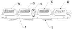
图1是本发明四腔体插头的结构示意图。FIG. 1 is a schematic structural diagram of a four-cavity plug of the present invention.
图2是本发明四腔体插座的结构示意图。FIG. 2 is a schematic structural diagram of a four-cavity socket of the present invention.
图3是本发明两腔体插座的结构示意图。FIG. 3 is a schematic structural diagram of a two-cavity socket of the present invention.
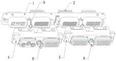
图4是用于机箱和设备之间连接时头座插合示意图。FIG. 4 is a schematic diagram of the plug-in connection of the head base when used for connection between the chassis and the equipment.
图5是用于设备和线缆之间连接或连接器测试时头座插合示意图。FIG. 5 is a schematic diagram of the plug-in connection between the device and the cable or the connector test.
图6是第一锁紧机构为锁紧导销机构的结构示例。FIG. 6 is a structural example in which the first locking mechanism is a locking guide pin mechanism.
图7是第二锁紧机构为识别导套机构的结构示例。FIG. 7 is a structural example in which the second locking mechanism is an identification guide sleeve mechanism.
图8是第一锁紧机构和第二锁紧机构锁紧状态示意图。FIG. 8 is a schematic diagram of the locking state of the first locking mechanism and the second locking mechanism.
【元件及符号说明】:【Component and Symbol Description】:
1-四腔体插头,2-接触件Ⅰ,3-四腔体插座,4-两腔体插座Ⅰ,5-两腔体插座Ⅱ,6-接触件Ⅱ,7-锁紧机构安装孔,8-第一锁紧机构,9-第二锁紧机构,10-识别导销,11-固定套,12-多边形导套,13-多边形导杆,14-螺纹导套,15-螺纹Ⅰ,16-螺纹Ⅱ,17-壳体,18-固定件,19-弹簧,20-固定端,21-台阶Ⅰ,22-固定件下端,23-插头绝缘体模块Ⅰ,24-插头绝缘体模块Ⅱ,25-插头绝缘体模块Ⅲ,26-插头绝缘体模块Ⅳ,27-插座绝缘体模块Ⅰ,28-插座绝缘体模块Ⅱ,29-插座绝缘体模块Ⅲ,30-插座绝缘体模块Ⅳ,31-识别导销底部,32-导销,33-导销安装孔。1- Four-chamber plug, 2- Contact piece I, 3- Four-chamber socket, 4- Two-chamber socket I, 5- Two-chamber socket II, 6- Contact piece II, 7- Mounting hole for locking mechanism, 8-First locking mechanism, 9-Second locking mechanism, 10-Identification guide pin, 11-Fixing sleeve, 12-Polygon guide sleeve, 13-Polygon guide rod, 14-Thread guide sleeve, 15-Thread I, 16-Thread II, 17-Housing, 18-Fixing piece, 19-Spring, 20-Fixing end, 21-Step I, 22-Fixing piece lower end, 23-Plug insulator module I, 24-Plug insulator module II, 25 -Plug insulator module III, 26-Plug insulator module IV, 27-Socket insulator module I, 28-Socket insulator module II, 29-Socket insulator module III, 30-Socket insulator module IV, 31- Identification guide pin bottom, 32- Guide pin, 33 - guide pin mounting hole.
具体实施方式Detailed ways
为进一步阐述本发明采取的技术手段和技术效果,以下结合附图及较佳实施例,对本发明进行详细说明。In order to further illustrate the technical means and technical effects adopted by the present invention, the present invention will be described in detail below with reference to the accompanying drawings and preferred embodiments.
由于设备上自带锁紧机构,机箱和设备之间连接对插的连接器上不需锁紧机构。而设备和线缆之间对插时需要连接器自带锁紧机构。本发明将插头设计为M个腔体结构可以装配M个插头绝缘体模块形成M腔体插头,插头绝缘体模块上装配相应的接触件Ⅰ2,为了使本发明的矩形模块化连接器能够同时适应直插拔连接,也能在必要的时候具备锁紧功能,本发明将用于和M腔体插头对插的插座设计为一体式和分体式两种结构,分别为一个M腔体插座和两个N腔体插座,M、N均为大于1的整数,且M=2N。Since the device has its own locking mechanism, there is no need for a locking mechanism on the connector that is connected between the chassis and the device. When the device and the cable are plugged together, the connector needs to have its own locking mechanism. In the present invention, the plug is designed to have M cavity structures, and M plug insulator modules can be assembled to form M cavity plugs. The plug insulator modules are equipped with corresponding contact pieces I2. In order to make the rectangular modular connector of the present invention suitable for direct insertion at the same time It can also have a locking function when necessary. The present invention designs two types of sockets, one-body type and one-piece type, for the sockets used to be inserted into the M-cavity plugs, which are one M-cavity socket and two N-cavity sockets respectively. For the cavity socket, M and N are both integers greater than 1, and M=2N.
M腔体插座上安装有M个插座绝缘体模块用于和插头上的M个插头绝缘体模块对插;两个N腔体插座包括N腔体插座Ⅰ和N腔体插座Ⅱ用于同时和M腔体插头对插,N腔体插座Ⅰ和N腔体插座Ⅱ上均设置有N个插座绝缘体模块且N腔体插座Ⅰ和N腔体插座Ⅱ上的插座绝缘体模块与M腔体插头上的插头绝缘体模块一一适配;插座绝缘体模块上装配有相应的接触件Ⅱ6用于和对应的插头绝缘体模块上的接触件Ⅰ2对插。M socket insulator modules are installed on the M cavity socket for mating with M plug insulator modules on the plug; the two N cavity sockets include N cavity socket I and N cavity socket II for simultaneous and M cavity sockets. The body plugs are inserted into each other, and N socket insulator modules are provided on both the N cavity socket I and the N cavity socket II, and the socket insulator modules on the N cavity socket I and the N cavity socket II and the plug on the M cavity plug The insulator modules are adapted one by one; the socket insulator module is equipped with a corresponding contact piece II6 for mating with the contact piece I2 on the corresponding plug insulator module.
M腔体插头和M腔体插座对插用于机箱和设备之间的连接。两个N腔体插座和一个M腔体插头同时对插用于设备和线缆之间的连接或者用于连接器测试使用,此时,连接器上需要自带锁紧机构。M腔体插头的壳体上设置有锁紧机构安装孔7,两个N腔体插座的壳体上均设置有第一锁紧机构8,当M腔体插头与两个N腔体插座对插时,在插头壳体的锁紧机构安装孔内装入第二锁紧机构9,头座对插后M腔体插头壳体上的第二锁紧机构与N腔体插座上的第一锁紧机构配合锁紧,实现连接器直插的同时具备锁紧功能。The M-cavity plug and the M-cavity socket are paired for connection between the chassis and the device. Two N-cavity sockets and one M-cavity plug are used for connection between equipment and cables or for connector testing. At this time, the connector needs to have its own locking mechanism. The housing of the M cavity plug is provided with a locking
进一步地,N腔体插座Ⅰ和N腔体插座Ⅱ上设置的第一锁紧机构可以是锁紧导销机构,包括识别导销10和固定套11,识别导销和固定套之间相对固定。固定套中部为多边形导套12,该多边形导套的内壁横截面为多边形用于和识别导销上的多边形导杆13配合,在使用工具转动识别导销时,固定套也能随之转动;多边形导杆横截面形状与多边形导套内壁横截面形状相同。图6-图8所示均为六方导套和六方导杆,其导套内壁横截面形状和导杆横截面形状均为六边形。固定套下部为螺纹导套14,该螺纹导套内壁设有螺纹Ⅰ15用于和识别导套机构中壳体上部插合端外壁的螺纹Ⅱ16配合从而使识别导套机构与螺纹导套螺纹连接。Further, the first locking mechanism provided on the N cavity socket I and the N cavity socket II may be a locking guide pin mechanism, including an
M腔体插头的壳体上锁紧机构安装孔内安装的第二锁紧机构可以是识别导套机构,包括壳体17和固定在壳体内部的固定件18以及装配在固定件外周的弹簧19。固定件上端设置有半球形或四面体形或其它多面体形的固定端20用于限位弹簧上端,弹簧下端被壳体底部的台阶Ⅰ21限位。弹簧被压缩或弹开时固定件下端22可以在壳体底部台阶Ⅰ的中心轴向移动(上下移动)。The second locking mechanism installed in the mounting hole of the locking mechanism on the housing of the M cavity plug can be an identification guide sleeve mechanism, including a housing 17, a fixing member 18 fixed inside the housing, and a spring assembled on the outer periphery of the fixing member 19. The upper end of the fixing piece is provided with a hemispherical or tetrahedral or other polyhedral-shaped fixing end 20 for limiting the upper end of the spring, and the lower end of the spring is limited by the step I21 at the bottom of the housing. When the spring is compressed or springs open, the lower end 22 of the fixing member can move axially (up and down) at the center of the step I at the bottom of the housing.
M腔体插头和两个N腔体插座对插时,两个N腔体插座上安装的插座绝缘体模块与插头上的插头绝缘体模块位置对应,两者对插后,通过插头壳体上的识别导套机构和插座上的锁紧导销机构配合锁紧实现连接器之间的锁紧功能。When the M cavity plug and two N cavity sockets are inserted into each other, the socket insulator module installed on the two N cavity sockets corresponds to the position of the plug insulator module on the plug. The guide sleeve mechanism and the locking guide pin mechanism on the socket cooperate and lock to realize the locking function between the connectors.
具体地,锁紧导销机构(第一锁紧机构)和识别导套机构(第二锁紧机构)锁紧的原理如下:Specifically, the locking principle of the locking guide pin mechanism (first locking mechanism) and the identification guide sleeve mechanism (second locking mechanism) is as follows:
头座对插后,识别导套机构壳体上部插合端外壁的螺纹Ⅱ16顺势插入螺纹导套14内,转动识别导销使螺纹导套与识别导套机构壳体上部插合端旋合进行螺纹连接,螺纹连接到位后实现连接器的锁紧。在螺纹连接过程中,识别导销底部31接近并压迫固定件上的固定端20使弹簧压缩。识别导套机构和锁紧导销机构插合到位并螺纹连接锁紧状态下,弹簧始终处于压缩状态使弹簧有反向的弹力,由于螺纹导套与识别导套机构壳体是螺纹连接,在弹簧弹力作用下使螺纹Ⅰ与螺纹Ⅱ之间始终顶紧并保持较大的顶紧力,从而实现锁紧及螺纹防松,即使在高震动环境下也不易松脱。After the head bases are inserted into each other, the thread II16 on the outer wall of the upper insertion end of the casing of the identification guide sleeve mechanism is inserted into the threaded
上述识别导套机构和锁紧导销机构仅是本发明锁紧结构的一种示例,当M腔体插头和N腔体插座对插用于设备和线缆之间的连接时,锁紧结构还可以有其他示例,只要能起到锁紧的效果即可。本发明的目的是提供一种多用途插合的多腔体矩形模块化连接器结构,在不改变插头连接器整体结构、不需重新进行连接器方案更改设计的前提下,实现连接器的直插拔或者在必要的时候采用锁紧式进行连接器连接。当用于机箱和设备之间连接时采用M腔体插头和M腔体插座对插,当用于设备和线缆之间连接或者在测试时(此时需要连接器具备锁紧功能)采用M腔体插头和两个带有第一锁紧机构的N腔体插座对插,并在插头上装配用于和第一锁紧机构配合锁紧的第二锁紧机构。M腔体插座和N腔体插座除了第一锁紧机构的差别,其它结构一致。The above-mentioned identification guide sleeve mechanism and locking guide pin mechanism are only an example of the locking structure of the present invention. When the M-cavity plug and the N-cavity socket are used for the connection between the equipment and the cable, the locking structure There can also be other examples, as long as the locking effect can be achieved. The purpose of the present invention is to provide a multi-cavity rectangular modular connector structure with multi-purpose insertion, without changing the overall structure of the plug connector and without the need to redesign the connector scheme, realize the direct connection of the connector. Plug-in or lock-on connector connections when necessary. When used for the connection between the chassis and the device, the M cavity plug and the M cavity socket are used for plugging, and when used for the connection between the device and the cable or when testing (the connector needs to have a locking function at this time), the M cavity is used. The cavity plug is inserted into two N cavity sockets with a first locking mechanism, and a second locking mechanism for cooperating and locking with the first locking mechanism is assembled on the plug. Except for the difference of the first locking mechanism, the M cavity socket and the N cavity socket have the same structure.
下面以M=4,N=2为例进行详细说明:The following takes M=4, N=2 as an example for detailed description:
如图1所示,四腔体插头1中的四个插头绝缘体模块包括插头绝缘体模块Ⅰ23、插头绝缘体模块Ⅱ24、插头绝缘体模块Ⅲ25、插头绝缘体模块Ⅳ26,四个插头绝缘体模块在插头的四个腔体内的安装位置不限定,可以根据需要在插头的四个腔体内任意装配。As shown in Figure 1, the four plug insulator modules in the four-
四腔体插座3上安装有四个插座绝缘体模块用于和插头上的四个插头绝缘体模块对插,四个插座绝缘体模块包括插座绝缘体模块Ⅰ27、插座绝缘体模块Ⅱ28、插座绝缘体模块Ⅲ29、插座绝缘体模块Ⅳ30,四个插座绝缘体模块在插座的四个腔体内的安装位置不限定,可以在插座的四个腔体内任意装配用于和插头上的四个插头绝缘体模块一一适配。Four socket insulator modules are installed on the four-
两腔体插座包括两腔体插座Ⅰ4和两腔体插座Ⅱ5用于同时和四腔体插头对插,两腔体插座Ⅰ和两腔体插座Ⅱ上均安装有两个插座绝缘体模块,插座绝缘体模块Ⅰ、插座绝缘体模块Ⅱ、插座绝缘体模块Ⅲ、插座绝缘体模块Ⅳ中的两个装配在两腔体插座Ⅰ上,其余两个装配在两腔体插座Ⅱ上,四个插座绝缘体模块在两个两腔体插座内的安装位置不限定,可以在两个两腔体插座的四个腔体内任意装配用于和插头上的四个插头绝缘体模块一一适配。Two-chamber sockets include two-chamber sockets I4 and two-chamber sockets II5, which are used for simultaneous insertion with four-chamber plugs. Two-chamber sockets I and two-chamber sockets II are installed with two socket insulator modules. Two of the module I, the socket insulator module II, the socket insulator module III, and the socket insulator module IV are assembled on the two-cavity socket I, the other two are assembled on the two-cavity socket II, and the four socket insulator modules are in two. The installation position in the two-cavity socket is not limited, and it can be arbitrarily assembled in the four cavities of the two two-cavity sockets for one-to-one matching with the four plug insulator modules on the plug.
当用于机箱和设备间的连接对插时,选用四腔体插头和一个四腔体插座对插,插头壳体的锁紧机构安装孔不安装第二锁紧机构,如图4所示。When it is used for the connection between the chassis and the equipment, a four-chamber plug and a four-chamber socket are selected for the matching, and the locking mechanism mounting hole of the plug housing is not equipped with a second locking mechanism, as shown in Figure 4.
当用于设备和线缆之间的连接对插时,选用四腔体插头和两个带有第一锁紧机构的两腔体插座对插,此时,在插头壳体上的锁紧机构安装孔内安装第二锁紧机构用于和两腔体插座上的第一锁紧机构配合锁紧,如图5所示。When it is used for the connection between the equipment and the cable, the four-chamber plug and the two two-chamber sockets with the first locking mechanism are used for the matching. At this time, the locking mechanism on the plug housing A second locking mechanism is installed in the installation hole for locking with the first locking mechanism on the two-cavity socket, as shown in FIG. 5 .
进一步地,M腔体插头的壳体上还设置有导销32,M腔体插座的壳体上对应设置有导销安装孔33用于在头座对插时起到引导作用,如图1-图2所示。Further, guide pins 32 are also provided on the housing of the M cavity plug, and guide pin mounting holes 33 are correspondingly provided on the housing of the M cavity socket for guiding when the headers are plugged together, as shown in FIG. 1 . - As shown in Figure 2.
以上所述,仅是本发明的较佳实施例而已,并非对本发明作任何形式上的限制,任何熟悉本专业的技术人员,在不脱离本发明技术方案范围内,依据本发明的技术实质对以上实施例所作的任何简单修改、等同变化与修饰,均仍属于本发明技术方案的范围内。The above are only preferred embodiments of the present invention, and are not intended to limit the present invention in any form. Any person skilled in the art, without departing from the scope of the technical solution of the present invention, will Any simple modifications, equivalent changes and modifications made in the above embodiments still fall within the scope of the technical solutions of the present invention.
Claims (4)
Priority Applications (1)
| Application Number | Priority Date | Filing Date | Title |
|---|---|---|---|
| CN201911167497.5ACN110854602B (en) | 2019-11-25 | 2019-11-25 | Multi-purpose plugged multi-cavity rectangular modular connector |
Applications Claiming Priority (1)
| Application Number | Priority Date | Filing Date | Title |
|---|---|---|---|
| CN201911167497.5ACN110854602B (en) | 2019-11-25 | 2019-11-25 | Multi-purpose plugged multi-cavity rectangular modular connector |
Publications (2)
| Publication Number | Publication Date |
|---|---|
| CN110854602Atrue CN110854602A (en) | 2020-02-28 |
| CN110854602B CN110854602B (en) | 2022-01-25 |
Family
ID=69604290
Family Applications (1)
| Application Number | Title | Priority Date | Filing Date |
|---|---|---|---|
| CN201911167497.5AActiveCN110854602B (en) | 2019-11-25 | 2019-11-25 | Multi-purpose plugged multi-cavity rectangular modular connector |
Country Status (1)
| Country | Link |
|---|---|
| CN (1) | CN110854602B (en) |
Cited By (2)
| Publication number | Priority date | Publication date | Assignee | Title |
|---|---|---|---|---|
| CN115000768A (en)* | 2022-05-20 | 2022-09-02 | 中航光电科技股份有限公司 | Novel shielding structure and connector using same |
| CN119787051A (en)* | 2025-01-03 | 2025-04-08 | 中航光电科技股份有限公司 | Novel connector with multiple monitoring functions and connector assembly |
Citations (6)
| Publication number | Priority date | Publication date | Assignee | Title |
|---|---|---|---|---|
| US4986769A (en)* | 1989-11-16 | 1991-01-22 | Amp Incorporated | Polarization and keying mechanism |
| CN1395342A (en)* | 2001-07-04 | 2003-02-05 | 日本航空电子工业株式会社 | Connector for many paired connector with different interface shape |
| CN201541025U (en)* | 2010-02-05 | 2010-08-04 | 陕西四菱电子有限责任公司 | On-site combined rectangle high-low frequency mixed connector |
| CN101944684A (en)* | 2009-07-07 | 2011-01-12 | 三美电机株式会社 | Connector |
| CN102969610A (en)* | 2011-08-29 | 2013-03-13 | 矢崎总业株式会社 | Multi-plug connection unit |
| CN103441380A (en)* | 2013-09-16 | 2013-12-11 | 上海航天科工电器研究院有限公司 | Anti-misplug IO (input/output) connector with locking function |
- 2019
- 2019-11-25CNCN201911167497.5Apatent/CN110854602B/enactiveActive
Patent Citations (6)
| Publication number | Priority date | Publication date | Assignee | Title |
|---|---|---|---|---|
| US4986769A (en)* | 1989-11-16 | 1991-01-22 | Amp Incorporated | Polarization and keying mechanism |
| CN1395342A (en)* | 2001-07-04 | 2003-02-05 | 日本航空电子工业株式会社 | Connector for many paired connector with different interface shape |
| CN101944684A (en)* | 2009-07-07 | 2011-01-12 | 三美电机株式会社 | Connector |
| CN201541025U (en)* | 2010-02-05 | 2010-08-04 | 陕西四菱电子有限责任公司 | On-site combined rectangle high-low frequency mixed connector |
| CN102969610A (en)* | 2011-08-29 | 2013-03-13 | 矢崎总业株式会社 | Multi-plug connection unit |
| CN103441380A (en)* | 2013-09-16 | 2013-12-11 | 上海航天科工电器研究院有限公司 | Anti-misplug IO (input/output) connector with locking function |
Cited By (3)
| Publication number | Priority date | Publication date | Assignee | Title |
|---|---|---|---|---|
| CN115000768A (en)* | 2022-05-20 | 2022-09-02 | 中航光电科技股份有限公司 | Novel shielding structure and connector using same |
| CN119787051A (en)* | 2025-01-03 | 2025-04-08 | 中航光电科技股份有限公司 | Novel connector with multiple monitoring functions and connector assembly |
| CN119787051B (en)* | 2025-01-03 | 2025-09-09 | 中航光电科技股份有限公司 | Connector and connector assembly with multiple monitoring functions |
Also Published As
| Publication number | Publication date |
|---|---|
| CN110854602B (en) | 2022-01-25 |
Similar Documents
| Publication | Publication Date | Title |
|---|---|---|
| CN100563064C (en) | Plate is to plate concentration mounting type RF coaxial connector | |
| CN101317304B (en) | Connector | |
| CN101657749B (en) | optical connector | |
| CN103337740B (en) | Component of RF coaxial connector with larger distance between plates | |
| CN102882053B (en) | Photoelectric mixed connector | |
| CN201247879Y (en) | Plate-to-plate concentration mounting type RF coaxial connector | |
| CN110854602A (en) | A multi-purpose mating multi-cavity rectangular modular connector | |
| CN208127515U (en) | A kind of waterproof electric connector | |
| CN106654760A (en) | Floating blind-mating radio frequency coaxial adapter | |
| CN109950761B (en) | Double-end floating radio frequency coaxial adapter | |
| CN115882293A (en) | Communication connector | |
| CN202797409U (en) | Multi-core cluster coaxial connector | |
| CN218919299U (en) | Power terminal, heavy-duty connector and heavy-duty connector assembly | |
| CN111244680A (en) | Connector integrated plug and connector integrated assembly | |
| CN216624804U (en) | Multi-PIN One-In Two-Out Adapters and Connectors | |
| CN117878666A (en) | Electronic connector with quick locking mechanism and use method thereof | |
| CN107565250A (en) | Connector | |
| CN116430081A (en) | Probes and Probe Components | |
| US11283224B1 (en) | Adapter mechanism | |
| CN212277509U (en) | Anti-loosening sealing electric connector special for case | |
| CN103326096B (en) | A kind of adapter of coaxial connector, socket and coaxial connector | |
| CN109143483B (en) | Integrated optical fiber connector and plug shell, socket shell and shell assembly thereof | |
| CN104300329A (en) | Mixed connector assembly with RJ45 modules | |
| CN104218385A (en) | Inter-board adapter and connector assembly with same | |
| CN222422467U (en) | Cable connector assembly and cable connecting mechanism |
Legal Events
| Date | Code | Title | Description |
|---|---|---|---|
| PB01 | Publication | ||
| PB01 | Publication | ||
| SE01 | Entry into force of request for substantive examination | ||
| SE01 | Entry into force of request for substantive examination | ||
| GR01 | Patent grant | ||
| GR01 | Patent grant |