CN110849420A - An experimental device for studying liquid carrying in undulating pipelines - Google Patents
An experimental device for studying liquid carrying in undulating pipelinesDownload PDFInfo
- Publication number
- CN110849420A CN110849420ACN201911173833.7ACN201911173833ACN110849420ACN 110849420 ACN110849420 ACN 110849420ACN 201911173833 ACN201911173833 ACN 201911173833ACN 110849420 ACN110849420 ACN 110849420A
- Authority
- CN
- China
- Prior art keywords
- pipeline
- experimental
- liquid
- pipe
- section
- Prior art date
- Legal status (The legal status is an assumption and is not a legal conclusion. Google has not performed a legal analysis and makes no representation as to the accuracy of the status listed.)
- Pending
Links
- 239000007788liquidSubstances0.000titleclaimsabstractdescription90
- 238000002474experimental methodMethods0.000claimsabstractdescription17
- XLYOFNOQVPJJNP-UHFFFAOYSA-NwaterSubstancesOXLYOFNOQVPJJNP-UHFFFAOYSA-N0.000claimsdescription38
- 239000011449brickSubstances0.000claimsdescription15
- VVQNEPGJFQJSBK-UHFFFAOYSA-NMethyl methacrylateChemical compoundCOC(=O)C(C)=CVVQNEPGJFQJSBK-UHFFFAOYSA-N0.000claimsdescription11
- 229920005372Plexiglas®Polymers0.000claimsdescription11
- 238000002347injectionMethods0.000claimsdescription8
- 239000007924injectionSubstances0.000claimsdescription8
- 235000007164Oryza sativaNutrition0.000claimsdescription6
- 238000005259measurementMethods0.000claimsdescription6
- 235000009566riceNutrition0.000claimsdescription6
- 230000001105regulatory effectEffects0.000claimsdescription5
- 239000012780transparent materialSubstances0.000claimsdescription5
- 239000000463materialSubstances0.000claimsdescription3
- 240000007594Oryza sativaSpecies0.000claims1
- 238000011160researchMethods0.000abstractdescription3
- 238000004088simulationMethods0.000abstractdescription3
- 238000012795verificationMethods0.000abstractdescription2
- 239000007789gasSubstances0.000description67
- VNWKTOKETHGBQD-UHFFFAOYSA-NmethaneChemical compoundCVNWKTOKETHGBQD-UHFFFAOYSA-N0.000description8
- 238000010586diagramMethods0.000description6
- 241000209094OryzaSpecies0.000description5
- 238000013461designMethods0.000description5
- 239000003345natural gasSubstances0.000description4
- 238000009825accumulationMethods0.000description3
- 230000000694effectsEffects0.000description3
- 238000000034methodMethods0.000description3
- 230000005540biological transmissionEffects0.000description2
- 238000005516engineering processMethods0.000description2
- 238000012360testing methodMethods0.000description2
- 2380000101463D printingMethods0.000description1
- 229910000831SteelInorganic materials0.000description1
- 238000005452bendingMethods0.000description1
- 230000009286beneficial effectEffects0.000description1
- 238000002485combustion reactionMethods0.000description1
- 230000007812deficiencyEffects0.000description1
- 238000011161developmentMethods0.000description1
- 230000007613environmental effectEffects0.000description1
- 239000012530fluidSubstances0.000description1
- NMJORVOYSJLJGU-UHFFFAOYSA-Nmethane clathrateChemical compoundC.C.C.C.O.O.O.O.O.O.O.O.O.O.O.O.O.O.O.O.O.O.O.O.O.O.ONMJORVOYSJLJGU-UHFFFAOYSA-N0.000description1
- 238000012986modificationMethods0.000description1
- 230000004048modificationEffects0.000description1
- 239000011347resinSubstances0.000description1
- 229920005989resinPolymers0.000description1
- 238000005070samplingMethods0.000description1
- 238000000926separation methodMethods0.000description1
- 238000009987spinningMethods0.000description1
- 239000010959steelSubstances0.000description1
- 238000012800visualizationMethods0.000description1
Images


Classifications
- G—PHYSICS
- G01—MEASURING; TESTING
- G01D—MEASURING NOT SPECIALLY ADAPTED FOR A SPECIFIC VARIABLE; ARRANGEMENTS FOR MEASURING TWO OR MORE VARIABLES NOT COVERED IN A SINGLE OTHER SUBCLASS; TARIFF METERING APPARATUS; MEASURING OR TESTING NOT OTHERWISE PROVIDED FOR
- G01D21/00—Measuring or testing not otherwise provided for
- G01D21/02—Measuring two or more variables by means not covered by a single other subclass
Landscapes
- Physics & Mathematics (AREA)
- General Physics & Mathematics (AREA)
- Measuring Volume Flow (AREA)
Abstract
Description
Translated fromChinese技术领域technical field
本发明涉及油气输送领域,尤其涉及一种用于研究起伏管线携液的实验装置。The invention relates to the field of oil and gas transportation, in particular to an experimental device for studying liquid carrying in undulating pipelines.
背景技术Background technique
近年来,随着对清洁能源需求的不断扩大,越来越多的天然气得到使用。而对天然气的输送最常用的方法就是管道输送,管道输送具有连续高效和安全稳定的特点,在天然气资源开发和输送过程中发挥着重要作用。输送过程中因环境等因素会在管道中产生积液尤其是在起伏管线的位置。积液的产生会影响天然气的输送甚至会生成天然气水合物堵塞管道危害管道安全,因此需要对积液进行排除并提高输送效率。螺旋流同时存在轴向及切向速度分量,且切向速度的作用不能忽略,在燃烧技术、水力输送、旋风分离、射流技术、气力输送等方面应用广泛。综上螺旋流也可以应用于起伏管线的携液领域,以减少管道堵塞,确保油气的安全输送。In recent years, as the demand for clean energy continues to expand, more and more natural gas has been used. The most commonly used method for natural gas transportation is pipeline transportation. Pipeline transportation has the characteristics of continuous efficiency, safety and stability, and plays an important role in the development and transportation of natural gas resources. During the transportation process, due to environmental and other factors, liquid accumulation will occur in the pipeline, especially in the position of the undulating pipeline. The generation of liquid accumulation will affect the transmission of natural gas and even generate natural gas hydrate to block the pipeline and endanger the safety of the pipeline. Therefore, it is necessary to remove the accumulated liquid and improve the transmission efficiency. Spiral flow has both axial and tangential velocity components, and the effect of tangential velocity cannot be ignored. It is widely used in combustion technology, hydraulic conveying, cyclone separation, jet technology, and pneumatic conveying. In summary, the spiral flow can also be applied to the liquid-carrying field of undulating pipelines to reduce pipeline blockage and ensure the safe transportation of oil and gas.
目前,对起伏管线携液的研究主要集中在流速和携液量方面,未将流型和压降考虑进去,缺乏完整和严谨性。因此,设计一种用于研究起伏管线携液并且兼顾流型、压降的实验装置,对于研究起伏管线携液的流动规律应用具有重要意义。At present, the research on liquid carrying in undulating pipelines mainly focuses on the flow rate and liquid carrying amount, and does not take into account the flow pattern and pressure drop, and lacks completeness and rigor. Therefore, designing an experimental device for studying liquid-carrying in undulating pipelines and taking into account the flow pattern and pressure drop is of great significance for the application of the flow law of liquid-carrying in undulating pipelines.
发明内容SUMMARY OF THE INVENTION
本发明要解决的技术问题是:为了克服现有技术之不足,本发明提供一种具有可视化的起伏管线,便于在实验中记录管线内部流型、压降,便于研究起伏管线携液的流动规律的一种用于研究起伏管线携液的实验装置。The technical problem to be solved by the present invention is: in order to overcome the deficiencies of the prior art, the present invention provides an undulating pipeline with visualization, which is convenient for recording the flow pattern and pressure drop inside the pipeline in the experiment, and is convenient for studying the flow law of the liquid carried by the undulating pipeline. An experimental device used to study liquid carrying in undulating pipelines.
本发明解决其技术问题所采用的技术方案是:一种用于研究起伏管线携液的实验装置,包括气相供给系统、实验管路系统和测量系统。The technical scheme adopted by the present invention to solve the technical problem is as follows: an experimental device for studying liquid carrying in an undulating pipeline, including a gas phase supply system, an experimental pipeline system and a measurement system.
所述的气相供给系统包括依次管路连接的空气压缩机、气体缓冲罐和混合器。The gas phase supply system includes an air compressor, a gas buffer tank and a mixer which are connected by pipelines in sequence.
所述的实验管路系统包括在混合器后依次通过法兰管路连接的进液管道、U型管和出液管道,所述的进液管道、U型管和出液管道均为透明材质。透明材质可便于流型的观察和记录。所述的进液管道与出液管道为水平管路,U型管包括对称设计的下倾段和上倾段,U型管下倾段前开有注水孔,进液管道内固定有起旋器,所述的实验管路系统还包括供U型管浸入的开口透明水箱,开口透明水箱内灌注有水且水深没过U型管的下端。在记录流型时,开口透明水箱内注满水可用于拍摄时减少管路带来的误差。The experimental pipeline system includes a liquid inlet pipe, a U-shaped pipe and a liquid outlet pipe connected by flange pipelines in sequence after the mixer, and the liquid inlet pipe, U-shaped pipe and liquid outlet pipe are all transparent materials. . The transparent material facilitates the observation and recording of flow patterns. The liquid inlet pipeline and the liquid outlet pipeline are horizontal pipelines. The U-shaped pipe includes a symmetrically designed downward slope section and an upward slope section. A water injection hole is opened in front of the downward slope section of the U-shaped tube, and a spinning is fixed in the liquid inlet pipeline. The experimental pipeline system also includes an open transparent water tank for the U-shaped pipe to be immersed, and the open transparent water tank is filled with water and the water depth does not exceed the lower end of the U-shaped pipe. When recording the flow pattern, the open transparent water tank filled with water can be used to reduce the error caused by the pipeline when shooting.
所述的测量系统包括气体流量计、压力传感器、若干压差传感器、温度传感器、光源和高速摄像机;所述的气体流量计位于气体缓冲罐与混合器之间的管路上,用于计量从气体缓冲罐出来的气体流量;所述的压力传感器位于进液管道上,且位于进液管道安装起旋器管路之前,用于测量系统的压力值;所述的压差传感器则分别位于U型管的下倾段、上倾段和出液管道所对应位置处,用于测量一定距离的压差值;所述的温度传感器则设置在出液管路中段位置处,用于测量系统的温度;所述的光源对应设置在U型管后方,高速摄像机则与光源对应并置于开口透明水箱前方,用于捕捉实验管段动态的流动特性,以分析其流动规律。The measuring system includes a gas flow meter, a pressure sensor, several differential pressure sensors, a temperature sensor, a light source and a high-speed camera; the gas flow meter is located on the pipeline between the gas buffer tank and the mixer, and is used to measure the gas from the gas. The gas flow from the buffer tank; the pressure sensor is located on the liquid inlet pipeline, and is located before the spinner pipeline is installed in the liquid inlet pipeline to measure the pressure value of the system; the differential pressure sensors are located in the U-shaped The position corresponding to the downward slope section, the upward slope section and the liquid outlet pipeline of the pipe is used to measure the pressure difference value of a certain distance; the temperature sensor is set in the middle section of the liquid outlet pipeline to measure the temperature of the system The light source is correspondingly arranged behind the U-shaped tube, and the high-speed camera corresponds to the light source and is placed in front of the open transparent water tank to capture the dynamic flow characteristics of the experimental pipe section to analyze its flow law.
在上述方案中,通过气相供给系统、实验管路系统和测量系统的配合,可通过高速摄像机拍摄起伏管线中的携液图像,同时由于实验管路采用多段式的连接,可根据需要跟换实验管段进行实验。In the above scheme, through the cooperation of the gas phase supply system, the experimental pipeline system and the measurement system, the liquid-carrying image in the undulating pipeline can be captured by a high-speed camera. At the same time, since the experimental pipeline adopts a multi-section connection, the experiment can be changed as needed. Pipe section for experiment.
进一步的,为了便于支撑整个实验装置,所述的实验管路系统下设有用于支撑实验管路系统的平台系统;所述的平台系统包括分别对应进液管道和出液管道下方设置的支架,所述的支架上固定有实验平台,所述的实验平台上则固定有支撑进液管道和出液管道的管托;进液管道下方的支架与出液管道下方的支架之间则连接有与U型管开口方向相对的U型支架。Further, in order to facilitate the support of the entire experimental device, the experimental pipeline system is provided with a platform system for supporting the experimental pipeline system; the platform system includes brackets corresponding to the liquid inlet pipeline and the liquid outlet pipeline respectively, An experimental platform is fixed on the support, and a tube holder supporting the liquid inlet pipeline and the liquid outlet pipeline is fixed on the experimental platform; and the bracket below the liquid inlet pipeline and the liquid outlet pipeline are connected with each other. A U-shaped bracket with the opening direction of the U-shaped tube opposite.
进一步的,为了便于模拟螺旋流的产生,便于在进液管道内安装起旋器,所述的进液管道包括法兰连接的第一段实验管道和第二段实验管道,所述的压力传感器位于第一段实验管道末端,所述的起旋器则固定在第一段实验管道与第二段实验管道之间的法兰中,所述的起旋器包括中心轴和环绕在中心轴上的四个螺旋叶片。Further, in order to facilitate the generation of simulated spiral flow, it is convenient to install a spinner in the liquid inlet pipeline, and the liquid inlet pipeline includes the first section of the experimental pipeline and the second section of the experimental pipeline connected by flanges. The pressure sensor Located at the end of the first section of the experimental pipeline, the spinner is fixed in the flange between the first section of the experimental pipeline and the second section of the experimental pipeline. of four helical blades.
进一步的,所述的出液管道包括第三段实验管道,所述第三段实验管道前端与U型管法兰连接,该法兰后的第三实验管道外固定有透明方砖,所述的透明方砖上表面具有供第三实验管道配合嵌入的柱形中空。透明方砖可有效减少拍摄时圆形出液管道所带来的误差。所述的第三段实验管道尾端通过法兰连接有弯头,所述弯头尾端连接有软管,软管尾端出水口处设有承接出水的水桶,水桶为敞口圆柱形水桶,用于收集被实验中气体携带出来的液体。Further, the liquid outlet pipeline includes a third section of the experimental pipeline, the front end of the third section of the experimental pipeline is connected with the U-shaped pipe flange, the third experimental pipeline behind the flange is fixed with transparent square bricks, the The upper surface of the transparent square brick has a cylindrical hollow for the third experimental pipeline to fit into. The transparent square brick can effectively reduce the error caused by the circular liquid outlet pipe during shooting. The tail end of the third section of the experimental pipeline is connected with an elbow through a flange, the tail end of the elbow is connected with a hose, and the water outlet at the tail end of the hose is provided with a bucket for receiving water, and the bucket is an open cylindrical bucket. , used to collect the liquid carried by the gas in the experiment.
所述的空气压缩机与气体缓冲罐之间的管路上设有止回阀。止回阀可以使压缩气体从空气压缩机流向气体缓冲罐而防止压缩气体从气体缓冲罐回流至空气压缩机。所述的气体缓冲罐与气体流量计之间的管路上还设有气体流量调节阀。所述的气体缓冲罐顶部设有弹簧式安全阀和压力表。当罐内压力将要超过气体缓冲罐的承压能力时,弹簧式安全阀可自动打开向外界释放气体,防止气体缓冲罐损坏。A check valve is provided on the pipeline between the air compressor and the gas buffer tank. The check valve allows compressed gas to flow from the air compressor to the gas buffer tank and prevents the backflow of compressed gas from the gas buffer tank to the air compressor. A gas flow regulating valve is also provided on the pipeline between the gas buffer tank and the gas flow meter. The top of the gas buffer tank is provided with a spring-type safety valve and a pressure gauge. When the pressure in the tank is about to exceed the pressure-bearing capacity of the gas buffer tank, the spring-type safety valve can automatically open to release the gas to the outside world to prevent the gas buffer tank from being damaged.
进一步的,开口透明水箱与进液管道、U型管和出液管道均采用相同的有机玻璃材质制成。Further, the open transparent water tank, the liquid inlet pipe, the U-shaped pipe and the liquid outlet pipe are all made of the same plexiglass material.
进一步的,混合器内布满长条状波浪板,使空气在实验管道中均匀分布,确保实验系统稳定运行。Further, the mixer is covered with long strips of wave plates, so that the air is evenly distributed in the experimental pipeline and ensures the stable operation of the experimental system.
进一步的,光源与U型管之间设有宣纸,在光源前覆盖一层宣纸,可有效均匀光线,改善拍摄效果。Further, rice paper is arranged between the light source and the U-shaped tube, and a layer of rice paper is covered in front of the light source, which can effectively uniform the light and improve the shooting effect.
本发明的有益效果是,本发明提供的一种用于研究起伏管线携液的实验装置,结构设计合理,通过气相供给系统、实验管路系统和测量系统的配合,可通过高速摄像机拍摄起伏管线中的携液图像;灵活性高,可通过更换实验管段进行其他实验,如起伏管线段更换为弯管则可以进行弯管实验;准确性好,高速摄像机、压差传感器、压力传感器和流量传感器均为高精度、高灵敏性的仪器,测量的数据准确可靠;同时安全性能好,能有效控制气体缓冲罐内气体压力,避免发生损坏。The beneficial effect of the present invention is that the present invention provides an experimental device for studying liquid-carrying of undulating pipelines, with a reasonable structure design, and through the cooperation of the gas phase supply system, the experimental pipeline system and the measuring system, the undulating pipeline can be photographed by a high-speed camera Liquid-carrying image in the middle; high flexibility, other experiments can be carried out by replacing the experimental pipe section, such as replacing the undulating pipeline section with a curved pipe, the pipe bending experiment can be carried out; good accuracy, high-speed camera, differential pressure sensor, pressure sensor and flow sensor They are all high-precision, high-sensitivity instruments, and the measured data is accurate and reliable; at the same time, the safety performance is good, and the gas pressure in the gas buffer tank can be effectively controlled to avoid damage.
附图说明Description of drawings
下面结合附图和实施例对本发明进一步说明。The present invention will be further described below in conjunction with the accompanying drawings and embodiments.
图1是本发明最优实施例的结构示意图。FIG. 1 is a schematic structural diagram of a preferred embodiment of the present invention.
图2是本发明最优实施例中起旋器的结构示意图。FIG. 2 is a schematic structural diagram of a spinner in the preferred embodiment of the present invention.
图3是本发明最优实施例中开口透明水箱的结构示意图。3 is a schematic structural diagram of an open transparent water tank in a preferred embodiment of the present invention.
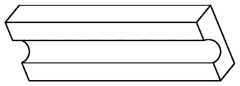
图4是本发明最优实施例中有机玻璃方砖的结构示意图。FIG. 4 is a schematic structural diagram of a plexiglass square brick in the preferred embodiment of the present invention.
图5是本发明最优实施例中有机玻璃方砖组成透明方砖的结构示意图。FIG. 5 is a schematic structural diagram of transparent square bricks composed of plexiglass square bricks in the preferred embodiment of the present invention.
图中1、空气压缩机 2、止回阀 3、弹簧式安全阀 4、压力表 5、气体缓冲罐 6、气体流量调节阀 7、气体流量计 8、混合器 9、第一段实验管道 10、温度传感器 11、起旋器 12、第二段实验管道 13、宣纸 14、注水孔 15、U型管 16、开口透明水箱 17、U型支架 18、高速摄像机 19、管托 20、透明方砖 21、第三段实验管道 22、实验平台 23、弯头 24、软管 25、水桶 26、压力传感器 27、压差传感器 28、支架 29、光源。In the figure 1, air compressor 2,
具体实施方式Detailed ways
现在结合附图对本发明作进一步详细的说明。这些附图均为简化的示意图,仅以示意方式说明本发明的基本结构,因此其仅显示与本发明有关的构成。The present invention will now be described in further detail with reference to the accompanying drawings. These drawings are all simplified schematic diagrams, and only illustrate the basic structure of the present invention in a schematic manner, so they only show the structures related to the present invention.
如图1所示一种用于研究起伏管线携液的实验装置,是本发明最优实施例,包括气相供给系统、实验管路系统和测量系统。As shown in Fig. 1, an experimental device for studying liquid carrying in an undulating pipeline is the preferred embodiment of the present invention, including a gas phase supply system, an experimental pipeline system and a measurement system.
所述的气相供给系统包括依次管路连接的空气压缩机1、气体缓冲罐5和混合器8。混合器8内布满长条状波浪板,使空气在实验管道中均匀分布,确保实验系统稳定运行。The gas phase supply system includes an
空气压缩机1为螺杆式压缩机,排气压力0.7MPa,排气量为1.35m3/min;气体缓冲罐5容积为2m3。当气体缓冲罐5内气体的压力达到0.8MPa时,空气压缩机1自动停止工作,进入待机状态;当气体缓冲罐5内气体的压力小于0.6MPa时,空气压缩机1又自动开启,进入工作状态。The
所述的空气压缩机1与气体缓冲罐5之间的管路上设有止回阀2。止回阀2可以使压缩气体从空气压缩机1流向气体缓冲罐5而防止压缩气体从气体缓冲罐5回流至空气压缩机1。A check valve 2 is provided on the pipeline between the
所述的气体缓冲罐5与气体流量计7之间的管路上还设有气体流量调节阀6。气体流量调节阀6为DN25的闸阀,通过旋转阀门控制流量大小。A gas flow regulating valve 6 is also provided on the pipeline between the
所述的气体缓冲罐5顶部设有弹簧式安全阀3和压力表4。当罐内压力将要超过气体缓冲罐5的承压能力时,弹簧式安全阀3可自动打开向外界释放气体,防止气体缓冲罐5损坏。The top of the
所述的实验管路系统包括在混合器8后依次通过法兰管路连接的进液管道、U型管15和出液管道,所述的进液管道、U型管15和出液管道均为透明材质。透明材质可便于流型的观察和记录。所述的进液管道与出液管道为水平管路,U型管15包括对称设计的下倾段和上倾段。为了便于模拟携液,U型管15下倾段前开有注水孔14。注水孔14为U型管15前端的开孔,目的在于实验前向U型管15中注入达到实验所需液面,模拟起伏管线积液,注水完成后通过堵头密封注水孔,随后进行气体在起伏管线中的携液实验。进液管道内固定有起旋器11,实验时气体通过起旋器11产生螺旋气流携带注水孔14注入U型管15中的液体前进模拟起伏管线携液实验。The experimental pipeline system includes a liquid inlet pipe, a
为了便于模拟螺旋流的产生,便于在进液管道内安装起旋器11,所述的进液管道包括法兰连接的第一段实验管道9和第二段实验管道12,所述的出液管道包括第三段实验管道21,所述第三段实验管道21前端与U型管15法兰连接,该法兰后的第三实验管道外固定有透明方砖20,所述的透明方砖20上表面具有供第三实验管道配合嵌入的半圆柱形镂空。In order to simulate the generation of the spiral flow, it is convenient to install the
在实际设计中,开口透明水箱16与进液管道、U型管15和出液管道均采用相同的有机玻璃材质制成。其中进液管道、出液管道为有机玻璃材质的透明管,其中第一段实验管道9和第二段实验管道12长0.3m,第三段实验管道21长1m,内径均为25mm,外径均为35mm,管与管之间通过尺寸为DN25的法兰连接而成。U型管15为有机玻璃材质的弯管,用于模拟输气管线的起伏管段,在下倾段和上倾段接有测压孔,用于接入压差传感器27测量携液时的压差变化。U型管15长0.7m,内径25mm,外径35mm,高度0.3m,通过法兰与两端的实验管道连接。透明方砖20是由两片长20cm、宽8cm,高5cm的有机玻璃方砖组成,且有机玻璃方砖一侧表面具有直径35mm的半圆柱形镂空,两片有机玻璃方砖前后夹在一起,半圆柱形镂空面对贴形成柱形中空,供第三段实验管道21配合嵌入放置,为第三段实验管道21提供有效支撑,可有效减少拍摄时第三段实验管道21所带来的误差。In the actual design, the open
所述的实验管路系统还包括供U型管15浸入的开口透明水箱16,开口透明水箱16内灌注有水且水深没过U型管15的下端。开口透明水箱16为有机玻璃材质,长0.5m,宽0.3m,高0.4m,上方的两边开了直径35mm的半圆,供U型管15两端放置。在记录流型时,开口透明水箱16向内注满水可用于拍摄时减少管路带来的误差。The experimental pipeline system also includes an open
所述的第三段实验管道21尾端通过法兰连接有弯头23,弯头23尺寸为DN25。所述弯头23尾端连接有软管24,软管24尾端出水口处设有承接出水的水桶25,水桶25为半径为20cm的敞口圆柱形水桶25,用于收集被实验中气体携带出来的液体。The end of the third section of the
所述的起旋器11则固定在第一段实验管道9与第二段实验管道12之间的法兰中,所述的起旋器11包括中心轴和环绕在中心轴上的四个螺旋叶片。起旋器11由光敏树脂通过3D打印制成,螺旋叶片倾角60°、厚度2mm。四个螺旋叶片旋转180°均匀分布在中心轴上,中心轴直径为15mm,用于产生螺旋流。The
所述的测量系统包括气体流量计7、压力传感器、若干压差传感器27、温度传感器10、光源29和高速摄像机18。The described measurement system includes a gas flow meter 7 , a pressure sensor, several
所述的气体流量计7位于气体缓冲罐5与混合器8之间的管路上,用于计量从气体缓冲罐5出来的气体流量,气体流量计7优选为涡轮流量计,量程范围为2.5-25m3/h。The gas flow meter 7 is located on the pipeline between the
所述的压力传感器位于第一段实验管道9末端,量程范围为0-0.5MPa,用于测量系统的压力值。The pressure sensor is located at the end of the first section of the
所述的压差传感器27则分别位于U型管15的下倾段、上倾段和出液管道所对应位置处,用于测量一定距离的压差值,量程范围为0-6.22kPa。The
所述的温度传感器10则设置在第三段实验管道21的透明方砖20后方的位置处,用于测量系统的温度,量程范围为0-100℃。The temperature sensor 10 is arranged at a position behind the transparent
所述的光源29对应设置在U型管15后方,为两组41cm、30W的LED灯,用于给高速摄像机18照明。光源29与U型管15之间设有宣纸13,在光源29前覆盖一层宣纸13,可有效均匀光线,改善拍摄效果。The
高速摄像机18则与光源29对应并置于开口透明水箱16前方,最高帧率为10000帧/秒,满幅分辨率为2048×1088。用于捕捉实验管段动态的流动特性,以分析其流动规律。The high-
为了便于支撑整个实验装置,所述的实验管路系统下设有用于支撑实验管路系统的平台系统;所述的平台系统包括分别对应进液管道和出液管道下方设置的支架28,所述的支架28上固定有实验平台22,所述的实验平台22上则固定有支撑进液管道和出液管道的管托19,管托19内径为35mm,用于将有机玻璃材质的管道与实验平台22固定。在实际设计中,可分别对应进液管道和出液管道设计两个长度分别为0.7m、1.2m,宽12cm的槽钢作为实验平台22,用于支撑实验设备。进液管道下方的支架28与出液管道下方的支架28之间则连接有与U型管15开口方向相对的U型支架17。In order to facilitate the support of the entire experimental device, the experimental pipeline system is provided with a platform system for supporting the experimental pipeline system; the platform system includes
在实验过程中,通过气相供给系统、实验管路系统和测量系统的配合,模拟起伏管线携液,并通过高速摄像机18记录流型,便于对管段内动态流动进行特性规律分析,实现实验室条件下对起伏管线携液的流动规律以及压降特性的研究,对数值模拟结果进行实验验证,完善气体携液的流动机理,同时结合流型和压降对气体携液能力展开研究,具有灵活性强,占用空间小和便于操作等优点。During the experiment, through the cooperation of the gas phase supply system, the experimental pipeline system and the measurement system, the liquid carrying of the undulating pipeline is simulated, and the flow pattern is recorded by the high-
由于实验管路系统通过法兰进行多段式的分段安装,更可根据需要通过更换实验管段进行其他实验,例如将起伏管线段更换为上倾弯管,则可进行上倾弯管携液的实验分析。气相供给系统设计合理,通过气体缓冲罐5的设计,提高安全性能,在罐内压力过高时,可及时自动向外释放气体,防止气体缓冲罐5发生损坏。而配合采样设计的高速摄像机18和光源29的配合,使得采集流型数据稳定可靠,同时压差传感器27、压力传感器和流量传感器均为高精度、高灵敏性仪器,采集数据准确可靠,有效提高了实验的准确性和可靠性。Since the experimental pipeline system is installed in multiple sections through flanges, other experiments can be carried out by replacing the experimental pipe sections as needed. experiment analysis. The gas phase supply system is reasonably designed. The design of the
以上述依据本发明的理想实施例为启示,通过上述的说明内容,相关工作人员完全可以在不偏离本项发明技术思想的范围内,进行多样的变更以及修改。本项发明的技术性范围并不局限于说明书上的内容,必须要根据权利要求范围来确定其技术性范围。Taking the above ideal embodiments according to the present invention as inspiration, and through the above description, relevant personnel can make various changes and modifications without departing from the technical idea of the present invention. The technical scope of the present invention is not limited to the contents in the specification, and the technical scope must be determined according to the scope of the claims.
Claims (8)
Translated fromChinesePriority Applications (1)
| Application Number | Priority Date | Filing Date | Title |
|---|---|---|---|
| CN201911173833.7ACN110849420A (en) | 2019-11-26 | 2019-11-26 | An experimental device for studying liquid carrying in undulating pipelines |
Applications Claiming Priority (1)
| Application Number | Priority Date | Filing Date | Title |
|---|---|---|---|
| CN201911173833.7ACN110849420A (en) | 2019-11-26 | 2019-11-26 | An experimental device for studying liquid carrying in undulating pipelines |
Publications (1)
| Publication Number | Publication Date |
|---|---|
| CN110849420Atrue CN110849420A (en) | 2020-02-28 |
Family
ID=69604516
Family Applications (1)
| Application Number | Title | Priority Date | Filing Date |
|---|---|---|---|
| CN201911173833.7APendingCN110849420A (en) | 2019-11-26 | 2019-11-26 | An experimental device for studying liquid carrying in undulating pipelines |
Country Status (1)
| Country | Link |
|---|---|
| CN (1) | CN110849420A (en) |
Cited By (1)
| Publication number | Priority date | Publication date | Assignee | Title |
|---|---|---|---|---|
| CN114741642A (en)* | 2022-03-22 | 2022-07-12 | 陕西延长石油(集团)有限责任公司 | Method for calculating critical liquid carrying flow rate of multi-lodging pipe sections |
Citations (7)
| Publication number | Priority date | Publication date | Assignee | Title |
|---|---|---|---|---|
| CN102507423A (en)* | 2011-10-14 | 2012-06-20 | 崔铭伟 | Testing apparatus for internal corrosion of circulating multiphase flow undulating pipeline |
| CN202803126U (en)* | 2012-06-26 | 2013-03-20 | 上海华之邦能源科技有限公司 | Venturi gas mixing device |
| CN205796995U (en)* | 2016-07-25 | 2016-12-14 | 环境保护部南京环境科学研究所 | A kind of accurate air distributing device of laboratory exhaust gas processing system |
| CN108051180A (en)* | 2017-11-17 | 2018-05-18 | 中国石油大学(华东) | A kind of circulating multiphase flow fluctuating pipeline experimental rig, application and method |
| CN110115956A (en)* | 2018-02-06 | 2019-08-13 | 中国石油天然气股份有限公司 | Pipeline mixer |
| CN209432776U (en)* | 2018-11-27 | 2019-09-24 | 中国石油化工股份有限公司 | Gas-liquid phase pipe experimental provision |
| CN110487508A (en)* | 2019-08-20 | 2019-11-22 | 常州大学 | A kind of experimental provision for research level pipe gas-liquid two-phase spiral flow |
- 2019
- 2019-11-26CNCN201911173833.7Apatent/CN110849420A/enactivePending
Patent Citations (7)
| Publication number | Priority date | Publication date | Assignee | Title |
|---|---|---|---|---|
| CN102507423A (en)* | 2011-10-14 | 2012-06-20 | 崔铭伟 | Testing apparatus for internal corrosion of circulating multiphase flow undulating pipeline |
| CN202803126U (en)* | 2012-06-26 | 2013-03-20 | 上海华之邦能源科技有限公司 | Venturi gas mixing device |
| CN205796995U (en)* | 2016-07-25 | 2016-12-14 | 环境保护部南京环境科学研究所 | A kind of accurate air distributing device of laboratory exhaust gas processing system |
| CN108051180A (en)* | 2017-11-17 | 2018-05-18 | 中国石油大学(华东) | A kind of circulating multiphase flow fluctuating pipeline experimental rig, application and method |
| CN110115956A (en)* | 2018-02-06 | 2019-08-13 | 中国石油天然气股份有限公司 | Pipeline mixer |
| CN209432776U (en)* | 2018-11-27 | 2019-09-24 | 中国石油化工股份有限公司 | Gas-liquid phase pipe experimental provision |
| CN110487508A (en)* | 2019-08-20 | 2019-11-22 | 常州大学 | A kind of experimental provision for research level pipe gas-liquid two-phase spiral flow |
Non-Patent Citations (4)
| Title |
|---|
| 曹学文 等: "复杂地表气田集输管道的泡沫排液技术", 《油气储运》* |
| 王琦 等: "水平气井连续携液实验研究及模型评价", 《西南石油大学学报(自然科学版)》* |
| 饶永超 等: "基于高速摄像的直管内多相流动特性研究进展", 《科技通报》* |
| 魏纳 等: "高气液比垂直管流连续携液实验", 《力学与实践》* |
Cited By (1)
| Publication number | Priority date | Publication date | Assignee | Title |
|---|---|---|---|---|
| CN114741642A (en)* | 2022-03-22 | 2022-07-12 | 陕西延长石油(集团)有限责任公司 | Method for calculating critical liquid carrying flow rate of multi-lodging pipe sections |
Similar Documents
| Publication | Publication Date | Title |
|---|---|---|
| CN110487508B (en) | Experimental device for be used for studying horizontal pipe gas-liquid two-phase spiral flow | |
| CN201130143Y (en) | Porous medium material permeability coefficient determinator | |
| CN202141562U (en) | Coal-fired boiler air preheater air leakage online monitoring device | |
| CN102607990B (en) | A kind of whole-process automatic test device of coal sample desorption of mash gas speed | |
| CN102620998B (en) | Device and method for pressure test and drainage tests for waved pipeline | |
| CN103900842B (en) | A self-priming Venturi scrubber performance test system | |
| CN106198932B (en) | The experimental provision and method of water lithofacies interaction in a kind of simulation rock crack | |
| CN104729637A (en) | Turbine flowmeter online calibration system and method | |
| CN106290107A (en) | A kind of coarse intersection crack permeation flow tester and method | |
| CN112129470B (en) | Pipeline micro-leakage monitoring simulation experiment system of underground comprehensive pipe gallery | |
| CN103822839A (en) | Circular erosion test device for closed pipelines and using method of circular erosion test device | |
| CN100374842C (en) | A Measuring Device for Flat Wall Fluid Frictional Resistance Based on Open Cycle | |
| CN106567998A (en) | Gas pipeline leakage detection simulation experiment platform based on optical fiber temperature sensor | |
| CN208224038U (en) | A kind of experimental provision for surveying permeability during the rock failure mechanism of rock in real time with constant flow | |
| CN110530760A (en) | A kind of experimental provision developed with geometry and method of exchanging heat in fissure channel for analog study foam fracturing fluid | |
| CN110849420A (en) | An experimental device for studying liquid carrying in undulating pipelines | |
| CN208091955U (en) | Water-oil phase glues the experimental provision of wall temperature in the defeated pipeline of measurement set | |
| CN116537753A (en) | A multifunctional displacement system and method using CO2 | |
| CN205981916U (en) | Controllable rock lateral restraint expansion rate survey device of side direction confined pressure | |
| CN208187686U (en) | A kind of experimental rig for probing into surface drag reduction mechanism | |
| CN204027885U (en) | A kind of blast furnace gas dust content is measured and is used filter membrane sampling device | |
| CN106092850A (en) | A kind of experimental provision monitoring hole water-soluble matter migration rule | |
| CN201653765U (en) | Flue gas sampling device | |
| CN108760232A (en) | A kind of experimental rig and test method for probing into surface drag reduction mechanism | |
| CN209673685U (en) | A kind of experimental rig for ice berg freezing isolation technology |
Legal Events
| Date | Code | Title | Description |
|---|---|---|---|
| PB01 | Publication | ||
| PB01 | Publication | ||
| SE01 | Entry into force of request for substantive examination | ||
| SE01 | Entry into force of request for substantive examination | ||
| RJ01 | Rejection of invention patent application after publication | ||
| RJ01 | Rejection of invention patent application after publication | Application publication date:20200228 |