CN110849374B - Underground environment positioning method, device, equipment and storage medium - Google Patents
Underground environment positioning method, device, equipment and storage mediumDownload PDFInfo
- Publication number
- CN110849374B CN110849374BCN201911217135.2ACN201911217135ACN110849374BCN 110849374 BCN110849374 BCN 110849374BCN 201911217135 ACN201911217135 ACN 201911217135ACN 110849374 BCN110849374 BCN 110849374B
- Authority
- CN
- China
- Prior art keywords
- point cloud
- map
- frame
- pose
- current
- Prior art date
- Legal status (The legal status is an assumption and is not a legal conclusion. Google has not performed a legal analysis and makes no representation as to the accuracy of the status listed.)
- Active
Links
Images


Classifications
- G—PHYSICS
- G01—MEASURING; TESTING
- G01C—MEASURING DISTANCES, LEVELS OR BEARINGS; SURVEYING; NAVIGATION; GYROSCOPIC INSTRUMENTS; PHOTOGRAMMETRY OR VIDEOGRAMMETRY
- G01C21/00—Navigation; Navigational instruments not provided for in groups G01C1/00 - G01C19/00
- G01C21/20—Instruments for performing navigational calculations
- G—PHYSICS
- G01—MEASURING; TESTING
- G01S—RADIO DIRECTION-FINDING; RADIO NAVIGATION; DETERMINING DISTANCE OR VELOCITY BY USE OF RADIO WAVES; LOCATING OR PRESENCE-DETECTING BY USE OF THE REFLECTION OR RERADIATION OF RADIO WAVES; ANALOGOUS ARRANGEMENTS USING OTHER WAVES
- G01S7/00—Details of systems according to groups G01S13/00, G01S15/00, G01S17/00
- G01S7/48—Details of systems according to groups G01S13/00, G01S15/00, G01S17/00 of systems according to group G01S17/00
- G01S7/4802—Details of systems according to groups G01S13/00, G01S15/00, G01S17/00 of systems according to group G01S17/00 using analysis of echo signal for target characterisation; Target signature; Target cross-section
- G—PHYSICS
- G06—COMPUTING OR CALCULATING; COUNTING
- G06F—ELECTRIC DIGITAL DATA PROCESSING
- G06F16/00—Information retrieval; Database structures therefor; File system structures therefor
- G06F16/20—Information retrieval; Database structures therefor; File system structures therefor of structured data, e.g. relational data
- G06F16/29—Geographical information databases
- G—PHYSICS
- G06—COMPUTING OR CALCULATING; COUNTING
- G06F—ELECTRIC DIGITAL DATA PROCESSING
- G06F18/00—Pattern recognition
- G06F18/20—Analysing
- G06F18/23—Clustering techniques
Landscapes
- Engineering & Computer Science (AREA)
- Remote Sensing (AREA)
- Data Mining & Analysis (AREA)
- Radar, Positioning & Navigation (AREA)
- Physics & Mathematics (AREA)
- General Physics & Mathematics (AREA)
- Theoretical Computer Science (AREA)
- General Engineering & Computer Science (AREA)
- Databases & Information Systems (AREA)
- Life Sciences & Earth Sciences (AREA)
- Computer Networks & Wireless Communication (AREA)
- Automation & Control Theory (AREA)
- Artificial Intelligence (AREA)
- Bioinformatics & Cheminformatics (AREA)
- Bioinformatics & Computational Biology (AREA)
- Computer Vision & Pattern Recognition (AREA)
- Evolutionary Biology (AREA)
- Evolutionary Computation (AREA)
- Optical Radar Systems And Details Thereof (AREA)
Abstract
Translated fromChinese
Description
Translated fromChinese技术领域technical field
本发明涉及定位技术领域,尤其涉及一种地下环境定位方法、装置、设备及存储介质。The present invention relates to the technical field of positioning, in particular to an underground environment positioning method, device, equipment and storage medium.
背景技术Background technique
近年来,地面无人驾驶项目发展迅速,对提高整个交通行业安全及效率有重要作用。而地下封闭受限空间的特殊环境,是实现无人驾驶快速落地的首选场景,能大幅度改善作业的安全性并提高地下作业效率,进而为企业创造出更大的经济效益,其中,地下环境中的精确定位是关键。In recent years, the ground unmanned driving project has developed rapidly, which plays an important role in improving the safety and efficiency of the entire transportation industry. The special environment of underground closed and restricted space is the first choice for realizing the rapid landing of unmanned driving, which can greatly improve the safety of operations and improve the efficiency of underground operations, thereby creating greater economic benefits for enterprises. Among them, the underground environment Precise positioning in is key.
虽然在空旷环境下基于GNSS(全球定位卫星系统)的定位能实现厘米级的定位精度,但对地下矿山、地铁、管廊、消防、人防等地下特殊环境,由于无法接收到GPS(全球定位系统)信号,使得地下定位困难增加。针对地下环境的定位问题,早在20世纪90年代初就已应用低频电磁引导、超声波传感测量引导、基于视觉信标导航等进行地下定位与连续跟踪。此外,基于Wi-Fi(Wireless-Fidelity,无线保真)定位、蓝牙定位、RFID(Radio FrequencyIdentification,无线射频识别)定位、UWB(Ultra Wideband)定位、红外技术、超声波等定位技术也有广泛应用。但上述定位技术都需要在地下环境中安装相应的辅助定位装置,虽能提高定位精度,但是需要增加大量的设备与维护费用,同时由于地下空间环境粗糙,容易造成定位过程中的累计误差,特别是在旋转情况下,很容易出现位姿获取失败,使地下装备自主行走过程中的安全性大大降低。Although the positioning based on GNSS (Global Positioning Satellite System) can achieve centimeter-level positioning accuracy in an open environment, for underground special environments such as underground mines, subways, pipe corridors, fire protection, and civil air defense, it is impossible to receive GPS (Global Positioning System) ) signal, making underground positioning more difficult. Aiming at the positioning problem of the underground environment, as early as the early 1990s, low-frequency electromagnetic guidance, ultrasonic sensor measurement guidance, and visual beacon-based navigation have been used for underground positioning and continuous tracking. In addition, based on Wi-Fi (Wireless-Fidelity, wireless fidelity) positioning, Bluetooth positioning, RFID (Radio Frequency Identification, radio frequency identification) positioning, UWB (Ultra Wideband) positioning, infrared technology, ultrasonic positioning technology and other positioning technologies are also widely used. However, the above positioning technologies all need to install corresponding auxiliary positioning devices in the underground environment. Although they can improve the positioning accuracy, they need to increase a lot of equipment and maintenance costs. Especially in the case of rotation, it is easy to fail to obtain the pose, which greatly reduces the safety of the underground equipment during autonomous walking.
发明内容Contents of the invention
有鉴于此,本发明实施例提供了一种地下环境定位方法、装置、设备及存储介质,旨在提高地下环境中定位的精度,满足地下装备的自主行走的无人驾驶需求。In view of this, the embodiments of the present invention provide an underground environment positioning method, device, equipment, and storage medium, aiming at improving the positioning accuracy in the underground environment and meeting the unmanned driving requirements of autonomous walking of underground equipment.
本发明实施例的技术方案是这样实现的:The technical scheme of the embodiment of the present invention is realized like this:
本发明实施例提供了一种地下环境定位方法,包括:An embodiment of the present invention provides an underground environment positioning method, including:
获取扫描点云数据的特征点云;Obtain the feature point cloud of the scanned point cloud data;
以上一帧的位姿作为当前的初始位姿,基于当前帧的扫描点云数据的特征点云与上一帧的扫描点云数据的特征点云进行点云帧与帧匹配,确定当前的预测位姿;The pose of the previous frame is used as the current initial pose, and the point cloud frame-to-frame matching is performed based on the feature point cloud of the scanned point cloud data of the current frame and the feature point cloud of the scanned point cloud data of the previous frame to determine the current prediction pose;
基于当前帧的扫描点云数据的特征点云、所述当前的预测位姿和特征地图,进行点云帧与地图匹配,得到当前的修正位姿;Based on the feature point cloud of the scanned point cloud data of the current frame, the current predicted pose and the feature map, the point cloud frame is matched with the map to obtain the current corrected pose;
其中,所述特征地图是基于实时的激光里程计及建图(LOAM,Lidar Odometry andMapping in Real-time)生成的,且所述特征地图的构建过程中,基于点云与扫描设备间的距离对扫描点云数据进行修正。Wherein, the feature map is generated based on real-time laser odometer and mapping (LOAM, Lidar Odometry and Mapping in Real-time), and in the construction process of the feature map, based on the distance between the point cloud and the scanning device Scan point cloud data for correction.
本发明实施例还提供了一种地下环境定位装置,包括:The embodiment of the present invention also provides an underground environment positioning device, including:
获取模块,用于获取扫描点云数据的特征点云;Obtaining module, for obtaining the characteristic point cloud of scanned point cloud data;
预测模块,用于以上一帧的位姿作为当前的初始位姿,基于当前帧的扫描点云数据的特征点云与上一帧的扫描点云数据的特征点云进行点云帧与帧匹配,确定当前的预测位姿;The prediction module is used to use the pose of the previous frame as the current initial pose, and perform point cloud frame-to-frame matching based on the feature point cloud of the scanned point cloud data of the current frame and the feature point cloud of the scanned point cloud data of the previous frame , to determine the current predicted pose;
位姿确定模块,用于基于当前帧的扫描点云数据的特征点云、所述当前的预测位姿和特征地图,进行点云帧与地图匹配,得到当前的修正位姿;The pose determining module is used to perform point cloud frame and map matching based on the feature point cloud of the scanned point cloud data of the current frame, the current predicted pose and the feature map, to obtain the current corrected pose;
其中,所述特征地图是基于LOAM生成的,且所述特征地图的构建过程中,基于点云与扫描设备间的距离对扫描点云数据进行修正。Wherein, the feature map is generated based on LOAM, and during the construction of the feature map, the scanned point cloud data is corrected based on the distance between the point cloud and the scanning device.
本发明实施例又一种地下环境定位设备,包括:处理器和用于存储能够在处理器上运行的计算机程序的存储器,其中,所述处理器,用于运行计算机程序时,执行本发明任一实施例所述方法的步骤。Another underground environment positioning device according to an embodiment of the present invention includes: a processor and a memory for storing a computer program that can run on the processor, wherein, when the processor is used to run the computer program, perform any task of the present invention The steps of the method described in one embodiment.
本发明实施例还提供了一种存储介质,所述存储介质上存储有计算机程序,所述计算机程序被处理器执行时,实现本发明任一实施例所述方法的步骤。An embodiment of the present invention also provides a storage medium, on which a computer program is stored, and when the computer program is executed by a processor, the steps of the method described in any embodiment of the present invention are implemented.
本发明实施例提供的技术方案,通过基于当前帧的扫描点云数据的特征点云与上一帧的扫描点云数据的特征点云进行点云帧与帧匹配,确定当前的预测位姿;基于当前帧的扫描点云数据的特征点云、所述当前的预测位姿和特征地图,进行点云帧与地图匹配,得到当前的修正位姿,且特征地图是基于LOAM生成的,且所述特征地图的构建过程中,基于点云与扫描设备间的距离对扫描点云数据进行修正,实现了基于距离权重的地下环境的精确定位,能够提高地下环境中定位的精度,满足地下装备的自主行走的无人驾驶需求。In the technical solution provided by the embodiment of the present invention, the current predicted pose is determined by performing point cloud frame-to-frame matching based on the feature point cloud of the scanned point cloud data of the current frame and the feature point cloud of the scanned point cloud data of the previous frame; Based on the feature point cloud of the scanned point cloud data of the current frame, the current predicted pose and the feature map, the point cloud frame is matched with the map to obtain the current corrected pose, and the feature map is generated based on LOAM, and the obtained In the process of constructing the above feature map, the scanned point cloud data is corrected based on the distance between the point cloud and the scanning equipment, and the accurate positioning of the underground environment based on the distance weight is realized, which can improve the positioning accuracy in the underground environment and meet the needs of underground equipment. Unmanned driving requirements for autonomous walking.
附图说明Description of drawings
图1为本发明实施例地下环境定位方法的流程示意图;Fig. 1 is a schematic flow chart of an underground environment positioning method according to an embodiment of the present invention;
图2为本发明实施例中点云坐标系变换的示意图;Fig. 2 is the schematic diagram of point cloud coordinate system transformation in the embodiment of the present invention;
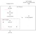
图3为本发明一实施例地下环境定位框架的示意图;3 is a schematic diagram of an underground environment positioning framework according to an embodiment of the present invention;
图4为本发明实施例地下环境定位装置的结构示意图;4 is a schematic structural diagram of an underground environment positioning device according to an embodiment of the present invention;
图5为本发明实施例地下环境定位设备的结构示意图。Fig. 5 is a schematic structural diagram of an underground environment positioning device according to an embodiment of the present invention.
具体实施方式Detailed ways
下面结合附图及实施例对本发明再作进一步详细的描述。The present invention will be further described in detail below in conjunction with the accompanying drawings and embodiments.
除非另有定义,本文所使用的所有的技术和科学术语与属于本发明的技术领域的技术人员通常理解的含义相同。本文中在本发明的说明书中所使用的术语只是为了描述具体的实施例的目的,不是旨在于限制本发明。Unless otherwise defined, all technical and scientific terms used herein have the same meaning as commonly understood by one of ordinary skill in the technical field of the invention. The terms used herein in the description of the present invention are for the purpose of describing specific embodiments only, and are not intended to limit the present invention.
相关技术中,三维激光雷达(又称为3D激光雷达)的出现,为地下环境的精确定位带来了便利,可以通过采集丰富的3D环境点云信息,实现高精度地图构建及定位的应用。发明人在实现本发明的过程中,发现三维激光雷达的采集点的距离越远,其测量误差越大,采集点距离越近,其测量误差越小。同时由于在地下环境中,其地面并不是十分平整,在三维激光雷达的移动过程中,少许的抖动更会增加远距离数据点(即点云)的测量误差。现有的SLAM(即时定位与地图构建)系统在建图过程中,一般是给地图划分栅格,根据实时点云数据的不断增加,对栅格内的点值进行不断的加权平均更新,求其均值和方差,很少考虑其测量误差,虽然LOAM中对运动畸变进行了去畸处理,但是没有考虑测量本身的误差对建图的影响。In related technologies, the emergence of three-dimensional laser radar (also known as 3D laser radar) has brought convenience to the precise positioning of the underground environment. It can realize the application of high-precision map construction and positioning by collecting rich 3D environmental point cloud information. In the process of implementing the present invention, the inventors found that the farther the distance between the collection points of the three-dimensional laser radar is, the greater the measurement error is, and the closer the collection points are, the smaller the measurement error is. At the same time, because the ground is not very smooth in the underground environment, a little shaking will increase the measurement error of long-distance data points (ie, point clouds) during the movement of the 3D lidar. In the process of building maps, the existing SLAM (real-time positioning and map construction) system generally divides the map into grids, and according to the continuous increase of real-time point cloud data, the point values in the grids are continuously weighted and averaged to update. The mean and variance rarely consider the measurement error. Although the motion distortion is de-distorted in LOAM, the influence of the error of the measurement itself on the mapping is not considered.
基于此,在本发明的各种实施例中,基于LOAM的地图构建过程中,基于点云与扫描设备间的距离对扫描点云数据进行修正,实现了基于距离权重的地下环境的精确定位,能够提高地下环境中定位的精度,满足地下装备的自主行走的无人驾驶需求。Based on this, in various embodiments of the present invention, in the LOAM-based map construction process, the scanned point cloud data is corrected based on the distance between the point cloud and the scanning device, and the precise positioning of the underground environment based on the distance weight is realized. It can improve the accuracy of positioning in the underground environment and meet the unmanned driving requirements of autonomous walking of underground equipment.
本发明实施例提供了一种地下环境定位方法,如图1所示,包括:An embodiment of the present invention provides an underground environment positioning method, as shown in Figure 1, including:
步骤101,获取扫描点云数据的特征点云;
步骤102,以上一帧的位姿作为当前的初始位姿,基于当前帧的扫描点云数据的特征点云与上一帧的扫描点云数据的特征点云进行点云帧与帧匹配,确定当前的预测位姿;
步骤103,基于当前帧的扫描点云数据的特征点云、所述当前的预测位姿和特征地图,进行点云帧与地图匹配,得到当前的修正位姿。
其中,所述特征地图是基于实时的激光里程计及建图(LOAM)生成的,且所述特征地图的构建过程中,基于点云与扫描设备间的距离对扫描点云数据进行修正。Wherein, the feature map is generated based on real-time laser odometry and mapping (LOAM), and during the construction of the feature map, the scanned point cloud data is corrected based on the distance between the point cloud and the scanning device.
本发明实施例中,由于特征地图是基于点云与扫描设备的距离进行修正后生成的,基于当前帧的扫描点云数据的特征点云、所述当前的预测位姿和特征地图,进行点云帧与地图匹配,得到当前的修正位姿,实现了基于距离权重的地下环境的精确定位,能够提高地下环境中定位的精度,满足地下装备的自主行走的无人驾驶需求。In the embodiment of the present invention, since the feature map is generated after correction based on the distance between the point cloud and the scanning device, based on the feature point cloud of the scanned point cloud data of the current frame, the current predicted pose, and the feature map, point The cloud frame is matched with the map to obtain the current corrected pose, which realizes the precise positioning of the underground environment based on the distance weight, which can improve the positioning accuracy in the underground environment and meet the unmanned driving requirements of autonomous walking of underground equipment.
在一实施例中,扫描设备为三维激光雷达。这里,以VLP-16三维激光雷达为例,VLP-16三维激光雷达是Velodyne公司出品的三维激光雷达。其竖直分辨率约为2°,水平分辨率最大为0.4°。把单个线束称为一个Scan,对全部16线组成的一帧点云称为一个Sweep。一帧内所有的点云,都是按顺序串行扫描的,同一个时间点,只会有一次发送,紧接着一次接收。先从水平第一个角度,一般在0°左右,扫描这个水平角度上竖直方向所有16个点(对应16个SCAN)的深度,当然这16个点也是串行按顺序的,然后转到下一个水平角度,比如0.3°开始,水平分辨率0.4°,那么下个角度就是0.7°,然后1.1°,一直顺时针扫完一圈,完成一个Sweep数据的采集,其输出形式为每个点云对应的(X,Y,Z,I),其中,(X,Y,Z)为三维坐标,I为反射强度值。In one embodiment, the scanning device is a three-dimensional lidar. Here, take the VLP-16 3D LiDAR as an example. The VLP-16 3D LiDAR is a 3D LiDAR produced by Velodyne. Its vertical resolution is about 2° and its horizontal resolution is up to 0.4°. A single wire harness is called a Scan, and a frame of point cloud composed of all 16 lines is called a Sweep. All point clouds in one frame are scanned serially in sequence. At the same time point, there will only be one transmission, followed by one reception. First start from the first horizontal angle, generally around 0°, scan the depth of all 16 points in the vertical direction (corresponding to 16 SCANs) at this horizontal angle, of course, these 16 points are also serial in order, and then go to The next horizontal angle, for example, starts at 0.3°, and the horizontal resolution is 0.4°, then the next angle is 0.7°, then 1.1°, and has been swept clockwise to complete a Sweep data collection, and its output form is each point (X, Y, Z, I) corresponding to the cloud, where (X, Y, Z) is the three-dimensional coordinates, and I is the reflection intensity value.
这里,地下环境定位设备获取三维激光雷达扫描得到的扫描点云数据,其中,一帧扫描点云数据即三维激光雷达扫描采集的一个Sweep数据。Here, the underground environment positioning device acquires scanning point cloud data obtained by three-dimensional lidar scanning, wherein one frame of scanning point cloud data is a Sweep data collected by three-dimensional lidar scanning.
本发明实施例中,地下环境定位设备获取到扫描点云数据后,对扫描点云数据基于无损卡尔曼滤波(UKF,Unscented Kalman Filter)构建特征地图、点云帧与帧匹配、点云帧与地图匹配的定位框架,实现地下环境的准确定位。其中,UKF是无损变换(UT)和标准卡尔曼(Kalman)滤波体系的结合,通过无损变换使非线性系统方程适用于线性假设下的标准卡尔曼滤波体系。UKF以UT变换为基础,摒弃了对非线性函数进行线性化的传统做法,采用卡尔曼线性滤波框架,对于一步预测方程,使用UT来处理均值和协方差的非线性传递,就成为UKF算法。UKF是对非线性函数的概率密度分布进行近似,用一系列确定样本来逼近状态的后验概率密度,而不是对非线性函数进行近似,不需要求导计算Jacobian(雅克比)矩阵。UKF没有线性化忽略高阶项,因此非线性分布统计量的计算精度较高。In the embodiment of the present invention, after the underground environment positioning device acquires the scanned point cloud data, it constructs a feature map, matches point cloud frames with frames, and matches point cloud frames with The positioning framework of map matching realizes the accurate positioning of the underground environment. Among them, UKF is a combination of lossless transformation (UT) and standard Kalman filter system, through lossless transformation, the nonlinear system equation is suitable for the standard Kalman filter system under the linear assumption. Based on UT transformation, UKF abandons the traditional method of linearizing nonlinear functions and adopts the Kalman linear filtering framework. For one-step prediction equations, using UT to handle the nonlinear transfer of mean and covariance becomes the UKF algorithm. UKF approximates the probability density distribution of the nonlinear function, and uses a series of determined samples to approximate the posterior probability density of the state, instead of approximating the nonlinear function, and does not need to calculate the Jacobian (Jacobian) matrix. UKF does not linearize and ignores higher-order terms, so the calculation accuracy of nonlinear distribution statistics is higher.
这里,地下环境定位设备对获取的扫描点云数据基于聚类方法进行噪声移除,提取扫描点云数据的特征点云。具体地,可以对噪声移除后的扫描点云数据采用LOAM中的特征提取方法进行特征提取,得到扫描点云数据的特征点云,比如,提取corner地图和surface地图对应的点云作为特征点云。在其他实施例中,扫描设备可以对扫描获取的扫描点云数据进行特征提取,得到扫描点云数据的特征点云并传送给地下环境定位设备,使得地下环境定位设备获取扫描点云数据的特征点云。Here, the underground environment positioning device performs noise removal on the acquired scanning point cloud data based on a clustering method, and extracts feature point clouds of the scanning point cloud data. Specifically, the feature extraction method in LOAM can be used to perform feature extraction on the scanned point cloud data after noise removal, and the feature point cloud of the scanned point cloud data can be obtained, for example, the point cloud corresponding to the corner map and the surface map can be extracted as feature points cloud. In other embodiments, the scanning device can perform feature extraction on the scanned point cloud data obtained by scanning, obtain the feature point cloud of the scanned point cloud data and send it to the underground environment positioning device, so that the underground environment positioning device can obtain the feature of the scanned point cloud data point cloud.
基于UKF的定位框架的地下环境定位包括:预测位姿阶段和修正位姿阶段。其中,预测位姿阶段即前述步骤102,修正位姿阶段即前述步骤103。The underground environment positioning based on the UKF positioning framework includes: the phase of predicting the pose and the phase of correcting the pose. Wherein, the pose prediction stage is the
这里,可以将上一帧的位姿作为当前的初始位姿,基于当前帧的扫描点云数据的特征点云与上一帧的扫描点云数据的特征点云进行点云帧与帧匹配,确定当前的预测位姿。Here, the pose of the previous frame can be used as the current initial pose, and point cloud frame-to-frame matching is performed based on the feature point cloud of the scanned point cloud data of the current frame and the feature point cloud of the scanned point cloud data of the previous frame, Determine the current predicted pose.
实际应用中,定义三维激光雷达的位姿状态向量为:In practical applications, the pose state vector of the 3D lidar is defined as:

其中,pt为t时刻的三维激光雷达的三维坐标,qt为t时刻的三维激光雷达的四元数。Among them, pt is the three-dimensional coordinates of the three-dimensional lidar at time t, and qt is the quaternion of the three-dimensional lidar at time t.
地下环境定位设备通过在连续帧之间迭代地应用所提取的特征点云确定三维激光雷达的预测位姿。具体地,可以基于当前帧的扫描点云数据的特征点云与上一帧的扫描点云数据的特征点云进行点云帧与帧(Scan to Scan)匹配,得到当前帧与上一帧间的相对位姿;基于所述相对位姿和上一帧的位姿得到当前的预测位姿。The subsurface environment localization device determines the predicted pose of 3D lidar by iteratively applying the extracted feature point cloud between consecutive frames. Specifically, point cloud frame-to-frame (Scan to Scan) matching can be performed based on the feature point cloud of the scanned point cloud data of the current frame and the feature point cloud of the scanned point cloud data of the previous frame to obtain the distance between the current frame and the previous frame. The relative pose; based on the relative pose and the pose of the previous frame, the current predicted pose is obtained.
示例性地,可以将实时获取的当前帧的特征点云与上一相邻帧的特征点云进行匹配,来获得重新扫描帧t时刻到最近帧t-1时刻的相对位姿Δxt-1,t=[Δpt,Δqt]T,同时t-1时刻三维激光雷达在世界坐标中的位姿为xt-1,则t时刻三维激光雷达的预测位姿计算如下:Exemplarily, the feature point cloud of the current frame acquired in real time can be matched with the feature point cloud of the previous adjacent frame to obtain the relative pose Δxt-1 from the rescanning frame t time to the latest frame t-1 time,t = [Δpt ,Δqt ]T , and the pose of the 3D lidar in the world coordinates at time t-1 is xt-1 , then the predicted pose of the 3D lidar at time t is calculated as follows:
xt=xt-1Δxt-1,txt = xt-1 Δxt-1,t
在一实施例中,所述基于当前帧的扫描点云数据的特征点云、所述当前的预测位姿和特征地图,进行点云帧与地图匹配,得到当前的修正位姿,包括:In one embodiment, the feature point cloud based on the scanned point cloud data of the current frame, the current predicted pose and the feature map are matched between the point cloud frame and the map to obtain the current corrected pose, including:
以所述当前的预测位姿作为点云帧与地图匹配的初始值,对当前帧的扫描点云数据的特征点云与特征地图进行点云帧与地图(Scan to Map)匹配得到配准位姿,将所述配准位姿作为当前的修正位姿。需要说明的是,在一实施例中,当前的修正位姿可以作为下一帧的初始位姿。若上一帧为第一帧时,则当前的初始位姿可以选取扫描设备的起始位置。Using the current predicted pose as the initial value of point cloud frame and map matching, carry out point cloud frame and map (Scan to Map) matching on the feature point cloud and feature map of the scanned point cloud data of the current frame to obtain the registration position pose, and use the registration pose as the current corrected pose. It should be noted that, in an embodiment, the current corrected pose can be used as the initial pose of the next frame. If the previous frame is the first frame, the current initial pose can select the starting position of the scanning device.
实际应用中,以所述预测位姿xt作为点云帧与地图匹配的初始值,通过点云帧与地图匹配,得到配准位姿为
由于在进行点云帧与地图匹配时,需要用到特征地图。基于此,在一实施例中,所述方法还包括:Because the feature map is needed when matching the point cloud frame with the map. Based on this, in one embodiment, the method also includes:
基于LOAM对已获取的扫描点云数据进行地图构建,得到初始的特征地图;Based on LOAM, map the acquired scanning point cloud data to obtain the initial feature map;
对所述初始的特征地图基于距离幂次反比法对特征点的距离赋予权值,得到修正后的特征地图。Weights are assigned to the distances of the feature points based on the distance inverse power method for the initial feature map to obtain the corrected feature map.
这里,所述基于LOAM对已获取的扫描点云数据进行地图构建,得到初始的特征地图,包括:Here, the LOAM-based map construction is performed on the acquired scanned point cloud data to obtain an initial feature map, including:
根据第一频率对已获取的扫描点云数据基于帧间匹配,得到相邻帧的数据间匹配的拼接位姿;According to the first frequency, based on the inter-frame matching of the acquired scanning point cloud data, the splicing poses matched between the data of adjacent frames are obtained;
根据第二频率对相邻帧的数据基于相应的拼接位姿拼接,得到初始的角corner地图和初始的面surface地图;According to the second frequency, the data of adjacent frames are spliced based on the corresponding splicing poses to obtain an initial corner map and an initial surface map;
其中,所述第一频率大于所述第二频率。Wherein, the first frequency is greater than the second frequency.
LOAM可以使用一个三维空间中运动的两轴激光雷达来获得低漂移和低复杂度,并且不需要高精度的测距和惯性测量的实时激光里程计和地图,其核心思想是将定位和建图的分割,通过两个算法:一个是执行高频率的里程计但是低精度的运动估计(定位),通过对每一帧激光的配准,可以得到一个精度较差的ODOM(里程计),由于没有IMU(惯性测量单元)提供帧间匹配的初始位姿,因此对LOAM进行少许改动,运用一个匀速运动模型来计算帧与帧配准的拼接位姿(POSE);另一个算法在一个数量级低的频率执行匹配和注册点云信息(建图和校正里程计),通过将多帧的激光特征点云基于拼接位姿拼接,形成特征点云地图(即前述的特征地图)。具体地,可以包括:corner地图和surface地图。这样,就建立了两种特征点云地图。此外,还可以将新入的帧与特征点云地图作配准,得到更精准的拼接位姿,并基于这个更精准的拼接位姿进行拼接,得到更新的特征点云地图;将这两个算法结合就获得了高精度、实时性的激光里程计。LOAM can use a two-axis lidar moving in three-dimensional space to obtain low drift and low complexity, and does not require high-precision ranging and inertial measurement of real-time laser odometer and map. The core idea is to combine positioning and mapping The segmentation, through two algorithms: one is to perform high-frequency odometer but low-precision motion estimation (positioning), through the registration of each frame of laser, you can get an ODOM (odometer) with poor accuracy, because There is no IMU (inertial measurement unit) to provide the initial pose for frame-to-frame matching, so a small change is made to LOAM, and a uniform motion model is used to calculate the spliced pose (POSE) for frame-to-frame registration; another algorithm is an order of magnitude lower The frequency of matching and registering point cloud information (mapping and odometry correction) is performed, and the feature point cloud map (that is, the aforementioned feature map) is formed by stitching the multi-frame laser feature point cloud based on the stitching pose. Specifically, it may include: a corner map and a surface map. In this way, two kinds of feature point cloud maps are established. In addition, new frames can be registered with the feature point cloud map to obtain a more accurate stitching pose, and based on this more accurate stitching pose, stitching can be performed to obtain an updated feature point cloud map; the two algorithms Combined to obtain a high-precision, real-time laser odometer.
本发明实施例中,还需要对特征点云地图基于距离幂次反比法对特征点的距离赋予权值,得到修正后的特征地图,包括:In the embodiment of the present invention, it is also necessary to assign weights to the distances of the feature points based on the inverse distance power method for the feature point cloud map, and obtain the corrected feature map, including:
将初始的corner地图和初始的corner地图的三维点云转换至世界坐标系并划分至世界坐标系下的三维栅格中;Convert the initial corner map and the 3D point cloud of the initial corner map to the world coordinate system and divide them into 3D grids under the world coordinate system;
针对每个栅格,统计各栅格内点云的个数,并基于各点云与设定位置的距离,对各点云进行权值赋值,确定各栅格对应的坐标;For each grid, count the number of point clouds in each grid, and assign weights to each point cloud based on the distance between each point cloud and the set position, and determine the coordinates corresponding to each grid;
根据各栅格对应的坐标更新初始的corner地图和corner地图,得到修正后的特征地图。The initial corner map and the corner map are updated according to the coordinates corresponding to each grid to obtain the corrected feature map.
实际应用中,对特征点云地图基于距离幂次反比法对特征点的距离赋予权值,得到修正后的特征地图,包括:In practical applications, weights are assigned to the distances of feature points based on the inverse distance power method for feature point cloud maps, and the corrected feature maps are obtained, including:
步骤1,依据得到的三维激光雷达的位姿信息,把激光雷达坐标系下的三维点云坐标转换到世界坐标系下,如图2所示。设三维激光雷达坐标系下三维点坐标为pL=(xL,yL,zL),三维激光雷达位姿信息用旋转矩阵TWL表示,则世界坐标系下三维点云坐标pW=(xW,yW,zW),满足如下公式:Step 1. According to the obtained 3D lidar pose information, transform the 3D point cloud coordinates in the lidar coordinate system into the world coordinate system, as shown in Figure 2. Suppose the coordinates of the 3D point in the 3D lidar coordinate system are pL =(xL , yL , zL ), and the pose information of the 3D lidar is represented by the rotation matrix TWL , then the coordinates of the 3D point cloud in the world coordinate system pW = (xW ,yW ,zW ), satisfy the following formula:
pW=TWL·pLpW =TWL ·pL
在三维激光雷达坐标系下,计算三维点云中任意一点距离三维激光雷达坐标原点的距离
步骤2,把世界坐标下的实时转换点云和局部地图点云划分到三维栅格中。当实时转换的点云为第一帧数据时,初始化点云地图,只需把第一帧转换点云划分到三维栅格中。在后续的三维激光帧中,需把转换点云和局部地图划分到三维栅格中。Step 2: Divide the real-time converted point cloud and local map point cloud in world coordinates into 3D grids. When the real-time converted point cloud is the first frame of data, to initialize the point cloud map, it is only necessary to divide the converted point cloud of the first frame into three-dimensional grids. In subsequent 3D laser frames, the converted point cloud and local map need to be divided into 3D grids.
针对每一个栅格,统计栅格内点云的个数n,根据激光雷达的测量特性,距离远的点其测量误差相对较大,依据上述点到激光雷达坐标系原点的距离S的计算方法,给每个点赋予相应的权值
根据转换后的三维点坐标和其相应的权重,计算每个栅格中此时刻最终点坐标pWC=(xWC,yWC,zWC),其满足如下公式:According to the converted three-dimensional point coordinates and their corresponding weights, calculate the final point coordinates pWC = (xWC , yWC , zWC ) in each grid at this moment, which satisfies the following formula:

根据最终点坐标pWC=(xWC,yWC,zWC),计算其在三维激光雷达坐标系下坐标pLC=(xLC,yLC,zLC),其满足如下公式:According to the final point coordinate pWC =(xWC ,yWC ,zWC ), calculate its coordinate pLC =(xLC ,yLC ,zLC ) in the three-dimensional lidar coordinate system, which satisfies the following formula:

并通过如下公式计算pLC与此时刻三维激光雷达坐标原点的距离:And the distance between pLC and the origin of the three-dimensional lidar coordinates at this moment is calculated by the following formula:

步骤3,依据得到的每一时刻位姿和其三维点云信息,不断迭代以上两个步骤,可以逐步对点云地图进行更新,得到受点云噪声影响小的完整三维点云地图(即修正后的特征地图)。Step 3: According to the obtained pose and its 3D point cloud information at each moment, the above two steps are continuously iterated, and the point cloud map can be gradually updated to obtain a complete 3D point cloud map that is less affected by point cloud noise (that is, corrected later feature maps).
如图3所示,在一实施例中,三维激光雷达采用Velodyne公司的VLP-16,地下环境精确定位框架主要分为基于3D激光雷达的离线距离权重点云地图构建和基于距离权重点云地图的实时精确定位。针对离线地图构建,首先基于LOAM生成Cornern地图和Surface地图,同时在生成地图过程中,根据3D激光雷达的数据采集特性,距离远的障碍物返回值较距离近的障碍物返回值偏移距离误差大,采用距离幂次反比法根据每个点的距离赋予不同的权值,进而对生成的特征地图进行修正,得到基于LOAM和距离幂次反比法的特征地图。针对基于距离权重地图的实时精确定位,为保证后续处理效率及定位精度,首先基于聚类方法进行噪声移除,同时采用LOAM中的特征提取方法对实时点云进行特征提取,得到特征点云;其次,基于无损卡尔曼滤波实现地下环境的实时定位。其中,在预测位姿阶段,主要通过点云帧间匹配进行位姿估计得到预测位姿;在修正位姿阶段,通过实时点云与构建的距离权重地图进行点云帧与地图,得到当前的修正位姿,最终输出实时精确位姿,同时该修正位姿也用于下一次循环的初始位姿。As shown in Figure 3, in one embodiment, the 3D lidar uses VLP-16 from Velodyne, and the precise positioning framework for the underground environment is mainly divided into offline distance-weighted key cloud map construction based on 3D lidar and distance-weighted key cloud map real-time precise positioning. For offline map construction, the Cornern map and Surface map are first generated based on LOAM. At the same time, in the process of generating the map, according to the data collection characteristics of 3D lidar, the return value of distant obstacles is offset by the distance error compared with the return value of short obstacles. Large, the distance inverse power method is used to assign different weights according to the distance of each point, and then the generated feature map is corrected to obtain a feature map based on LOAM and distance inverse power method. For the real-time precise positioning based on the distance weight map, in order to ensure the subsequent processing efficiency and positioning accuracy, the noise is firstly removed based on the clustering method, and the feature extraction method in LOAM is used to extract the features of the real-time point cloud to obtain the feature point cloud; Secondly, the real-time positioning of the underground environment is realized based on the lossless Kalman filter. Among them, in the pose prediction stage, the predicted pose is mainly obtained by point cloud inter-frame matching for pose estimation; in the pose correction stage, the point cloud frame and map are obtained through the real-time point cloud and the constructed distance weight map to obtain the current Correct the pose, and finally output the real-time accurate pose, and the corrected pose is also used for the initial pose of the next cycle.
实际应用中,将本发明实施例地下环境定位方法应用于在地下多个场景中进行测试,包括表面光滑直巷道、表面光滑回环巷道、粗糙非直巷道及粗糙斜坡道,通过定位误差及定位时间分析证明该算法实现地下环境的精准定位及算法的鲁棒性,并从定位误差、定位时间等方面进行对比分析,定位误差能控制在4cm左右,定位时间平均控制在60ms左右,结果表明该算法可以实现低漂移的实时定位。In practical applications, the underground environment positioning method according to the embodiment of the present invention is applied to multiple underground scenarios for testing, including smooth-surfaced straight roadways, smooth-surfaced loop roadways, rough non-straight roadways and rough slope roads. The analysis proves that the algorithm realizes the precise positioning of the underground environment and the robustness of the algorithm, and compares and analyzes the positioning error and positioning time. The positioning error can be controlled at about 4cm, and the average positioning time is controlled at about 60ms. The results show that the algorithm Real-time positioning with low drift can be achieved.
为了实现本发明实施例的方法,本发明实施例还提供一种地下环境定位装置,如图4所示,该装置包括:获取模块401、预测模块402、位姿确定模块403。其中,In order to implement the method of the embodiment of the present invention, the embodiment of the present invention also provides an underground environment positioning device, as shown in FIG. 4 , the device includes: an acquisition module 401 , a prediction module 402 , and a pose determination module 403 . in,
获取模块401,用于获取扫描点云数据的特征点云;Obtaining module 401, for obtaining the characteristic point cloud of scanned point cloud data;
预测模块402,用于以上一帧的位姿作为当前的初始位姿,基于当前帧的扫描点云数据的特征点云与上一帧的扫描点云数据的特征点云进行点云帧与帧匹配,确定当前的预测位姿;The prediction module 402 is used to use the pose of the previous frame as the current initial pose, based on the feature point cloud of the scanned point cloud data of the current frame and the feature point cloud of the scanned point cloud data of the previous frame to perform point cloud frame-to-frame Match to determine the current predicted pose;
位姿确定模块403,用于基于当前帧的扫描点云数据的特征点云、所述当前的预测位姿和特征地图,进行点云帧与地图匹配,得到当前的修正位姿;The pose determination module 403 is used for matching the point cloud frame with the map based on the feature point cloud of the scanned point cloud data of the current frame, the current predicted pose and the feature map to obtain the current corrected pose;
其中,所述特征地图是基于LOAM生成的,且所述特征地图的构建过程中,基于点云与扫描设备间的距离对扫描点云数据进行修正。Wherein, the feature map is generated based on LOAM, and during the construction of the feature map, the scanned point cloud data is corrected based on the distance between the point cloud and the scanning device.
在一实施例中,地下环境定位装置还包括:地图构建模块404,用于:In one embodiment, the underground environment positioning device further includes: a map construction module 404, configured to:
基于LOAM对已获取的扫描点云数据进行地图构建,得到初始的特征地图;Based on LOAM, map the acquired scanning point cloud data to obtain the initial feature map;
对所述初始的特征地图基于距离幂次反比法对特征点的距离赋予权值,得到修正后的特征地图。Weights are assigned to the distances of the feature points based on the distance inverse power method for the initial feature map to obtain the corrected feature map.
在一实施例中,地图构建模块404具体用于:In one embodiment, the map construction module 404 is specifically used for:
根据第一频率对已获取的扫描点云数据基于帧间匹配,得到相邻帧的数据间匹配的拼接位姿;According to the first frequency, based on the inter-frame matching of the acquired scanning point cloud data, the splicing poses matched between the data of adjacent frames are obtained;
根据第二频率对相邻帧的数据基于相应的拼接位姿拼接,得到初始的角corner地图和初始的面surface地图;According to the second frequency, the data of adjacent frames are spliced based on the corresponding splicing poses to obtain an initial corner map and an initial surface map;
其中,所述第一频率大于所述第二频率。Wherein, the first frequency is greater than the second frequency.
在一实施例中,地图构建模块404具体用于:In one embodiment, the map construction module 404 is specifically used for:
将初始的corner地图和初始的corner地图的三维点云转换至世界坐标系并划分至世界坐标系下的三维栅格中;Convert the initial corner map and the 3D point cloud of the initial corner map to the world coordinate system and divide them into 3D grids under the world coordinate system;
针对每个栅格,统计各栅格内点云的个数,并基于各点云与设定位置的距离,对各点云进行权值赋值,确定各栅格对应的坐标;For each grid, count the number of point clouds in each grid, and assign weights to each point cloud based on the distance between each point cloud and the set position, and determine the coordinates corresponding to each grid;
根据各栅格对应的坐标更新初始的corner地图和corner地图,得到修正后的特征地图。The initial corner map and the corner map are updated according to the coordinates corresponding to each grid to obtain the corrected feature map.
在一实施例中,预测模块402具体用于:In an embodiment, the prediction module 402 is specifically used for:
基于当前帧的扫描点云数据的特征点云与上一帧的扫描点云数据的特征点云进行点云帧与帧匹配,得到当前帧与上一帧间的相对位姿;Based on the feature point cloud of the scanned point cloud data of the current frame and the feature point cloud of the scanned point cloud data of the previous frame, the point cloud frame is matched with the frame to obtain the relative pose between the current frame and the previous frame;
基于所述相对位姿和上一帧的位姿得到当前的预测位姿。The current predicted pose is obtained based on the relative pose and the pose of the previous frame.
在一实施例中,位姿确定模块403具体用于:In one embodiment, the pose determining module 403 is specifically used for:
以所述当前的预测位姿作为点云帧与地图匹配的初始值,对当前帧的扫描点云数据的特征点云与特征地图进行点云帧与地图匹配得到配准位姿,将所述配准位姿作为当前的修正位姿。Using the current predicted pose as the initial value of point cloud frame and map matching, performing point cloud frame and map matching on the feature point cloud and feature map of the scanned point cloud data of the current frame to obtain the registration pose, and using the The registered pose is used as the current corrected pose.
实际应用时,获取模块401、预测模块402、位姿确定模块403及地图构建模块404,可以由地下环境定位装置中的处理器来实现。当然,处理器需要运行存储器中的计算机程序来实现它的功能。In actual application, the acquisition module 401, the prediction module 402, the pose determination module 403 and the map construction module 404 may be implemented by a processor in the underground environment positioning device. Of course, a processor needs to run a computer program in memory to carry out its functions.
需要说明的是:上述实施例提供的地下环境定位装置在进行地下环境定位时,仅以上述各程序模块的划分进行举例说明,实际应用中,可以根据需要而将上述处理分配由不同的程序模块完成,即将装置的内部结构划分成不同的程序模块,以完成以上描述的全部或者部分处理。另外,上述实施例提供的地下环境定位装置与地下环境定位方法实施例属于同一构思,其具体实现过程详见方法实施例,这里不再赘述。It should be noted that: when the underground environment locating device provided by the above-mentioned embodiments performs underground environment locating, the division of the above-mentioned program modules is used as an example for illustration. In practical applications, the above-mentioned processing can be assigned to different program modules as required Completion means that the internal structure of the device is divided into different program modules to complete all or part of the processing described above. In addition, the underground environment locating device provided in the above embodiments and the underground environment locating method embodiments belong to the same idea, and the specific implementation process thereof is detailed in the method embodiments, and will not be repeated here.
基于上述程序模块的硬件实现,且为了实现本发明实施例的方法,本发明实施例还提供一种地下环境定位设备。图5仅仅示出了该设备的示例性结构而非全部结构,根据需要可以实施图5示出的部分结构或全部结构。Based on the hardware implementation of the above program modules, and in order to implement the method of the embodiment of the present invention, the embodiment of the present invention further provides an underground environment positioning device. FIG. 5 only shows an exemplary structure of the device but not the entire structure, and part or all of the structures shown in FIG. 5 can be implemented as required.
如图5所示,本发明实施例提供的地下环境定位设备500包括:至少一个处理器501、存储器502、用户接口503和至少一个网络接口504。地下环境定位设备500中的各个组件通过总线系统505耦合在一起。可以理解,总线系统505用于实现这些组件之间的连接通信。总线系统505除包括数据总线之外,还包括电源总线、控制总线和状态信号总线。但是为了清楚说明起见,在图5中将各种总线都标为总线系统505。As shown in FIG. 5 , an underground
其中,用户接口503可以包括显示器、键盘、鼠标、轨迹球、点击轮、按键、按钮、触感板或者触摸屏等。Wherein, the
本发明实施例中的存储器502用于存储各种类型的数据以支持地下环境定位设备的操作。这些数据的示例包括:用于在地下环境定位设备上操作的任何计算机程序。The
本发明实施例揭示的地下环境定位方法可以应用于处理器501中,或者由处理器501实现。处理器501可能是一种集成电路芯片,具有信号的处理能力。在实现过程中,地下环境定位方法的各步骤可以通过处理器501中的硬件的集成逻辑电路或者软件形式的指令完成。上述的处理器501可以是通用处理器、数字信号处理器(DSP,Digital SignalProcessor),或者其他可编程逻辑器件、分立门或者晶体管逻辑器件、分立硬件组件等。处理器501可以实现或者执行本发明实施例中的公开的各方法、步骤及逻辑框图。通用处理器可以是微处理器或者任何常规的处理器等。结合本发明实施例所公开的方法的步骤,可以直接体现为硬件译码处理器执行完成,或者用译码处理器中的硬件及软件模块组合执行完成。软件模块可以位于存储介质中,该存储介质位于存储器502,处理器501读取存储器502中的信息,结合其硬件完成本发明实施例提供的地下环境定位方法的步骤。The underground environment positioning method disclosed in the embodiment of the present invention may be applied to the
在示例性实施例中,地下环境定位设备可以被一个或多个应用专用集成电路(ASIC,Application Specific Integrated Circuit)、DSP、可编程逻辑器件(PLD,Programmable Logic Device)、复杂可编程逻辑器件(CPLD,Complex Programmable LogicDevice)、FPGA、通用处理器、控制器、微控制器(MCU,Micro Controller Unit)、微处理器(Microprocessor)、或者其他电子元件实现,用于执行前述方法。In an exemplary embodiment, the underground environment positioning device may be implemented by one or more Application Specific Integrated Circuits (ASIC, Application Specific Integrated Circuit), DSP, Programmable Logic Device (PLD, Programmable Logic Device), complex programmable logic device ( CPLD, Complex Programmable LogicDevice), FPGA, general-purpose processor, controller, microcontroller (MCU, Micro Controller Unit), microprocessor (Microprocessor), or other electronic components are used to implement the aforementioned method.
在一应用示例中,地下环境定位设备包括16线3D激光雷达、移动电源及笔记本电脑,该移动电源供电给16线3D激光雷达和笔记本电脑,笔记本电脑与16线3D激光雷达通信连接,笔记本电脑运行计算机程序时,实现前述任一实施例所述的地下环境定位方法。In an application example, the underground environment positioning equipment includes a 16-line 3D laser radar, a mobile power supply and a notebook computer. The mobile power supply supplies power to the 16-line 3D laser radar and a notebook computer. When the computer program is run, the method for locating the underground environment described in any of the foregoing embodiments is realized.
可以理解,存储器502可以是易失性存储器或非易失性存储器,也可包括易失性和非易失性存储器两者。其中,非易失性存储器可以是只读存储器(ROM,Read Only Memory)、可编程只读存储器(PROM,Programmable Read-Only Memory)、可擦除可编程只读存储器(EPROM,Erasable Programmable Read-Only Memory)、电可擦除可编程只读存储器(EEPROM,Electrically Erasable Programmable Read-Only Memory)、磁性随机存取存储器(FRAM,ferromagnetic random access memory)、快闪存储器(Flash Memory)、磁表面存储器、光盘、或只读光盘(CD-ROM,Compact Disc Read-Only Memory);磁表面存储器可以是磁盘存储器或磁带存储器。易失性存储器可以是随机存取存储器(RAM,Random AccessMemory),其用作外部高速缓存。通过示例性但不是限制性说明,许多形式的RAM可用,例如静态随机存取存储器(SRAM,Static Random Access Memory)、同步静态随机存取存储器(SSRAM,Synchronous Static Random Access Memory)、动态随机存取存储器(DRAM,Dynamic Random Access Memory)、同步动态随机存取存储器(SDRAM,SynchronousDynamic Random Access Memory)、双倍数据速率同步动态随机存取存储器(DDRSDRAM,Double Data Rate Synchronous Dynamic Random Access Memory)、增强型同步动态随机存取存储器(ESDRAM,Enhanced Synchronous Dynamic Random Access Memory)、同步连接动态随机存取存储器(SLDRAM,SyncLink Dynamic Random Access Memory)、直接内存总线随机存取存储器(DRRAM,Direct Rambus Random Access Memory)。本发明实施例描述的存储器旨在包括但不限于这些和任意其它适合类型的存储器。It can be understood that the
在示例性实施例中,本发明实施例还提供了一种存储介质,即计算机存储介质,具体可以是计算机可读存储介质,例如包括存储计算机程序的存储器502,上述计算机程序可由地下环境定位设备的处理器501执行,以完成本发明实施例方法所述的步骤。计算机可读存储介质可以是ROM、PROM、EPROM、EEPROM、Flash Memory、磁表面存储器、光盘、或CD-ROM等存储器。In an exemplary embodiment, the embodiment of the present invention also provides a storage medium, that is, a computer storage medium, specifically a computer-readable storage medium, for example, including a
需要说明的是:“第一”、“第二”等是用于区别类似的对象,而不必用于描述特定的顺序或先后次序。It should be noted that: "first", "second", etc. are used to distinguish similar objects, and not necessarily used to describe a specific order or sequence.
另外,本发明实施例所记载的技术方案之间,在不冲突的情况下,可以任意组合。In addition, the technical solutions described in the embodiments of the present invention may be combined arbitrarily if there is no conflict.
以上所述,仅为本发明的具体实施方式,但本发明的保护范围并不局限于此,任何熟悉本技术领域的技术人员在本发明揭露的技术范围内,可轻易想到变化或替换,都应涵盖在本发明的保护范围之内。因此,本发明的保护范围应以权利要求的保护范围为准。The above is only a specific embodiment of the present invention, but the scope of protection of the present invention is not limited thereto. Anyone skilled in the art can easily think of changes or substitutions within the technical scope disclosed in the present invention. Should be covered within the protection scope of the present invention. Therefore, the protection scope of the present invention should be based on the protection scope of the claims.
Claims (6)
Priority Applications (1)
| Application Number | Priority Date | Filing Date | Title |
|---|---|---|---|
| CN201911217135.2ACN110849374B (en) | 2019-12-03 | 2019-12-03 | Underground environment positioning method, device, equipment and storage medium |
Applications Claiming Priority (1)
| Application Number | Priority Date | Filing Date | Title |
|---|---|---|---|
| CN201911217135.2ACN110849374B (en) | 2019-12-03 | 2019-12-03 | Underground environment positioning method, device, equipment and storage medium |
Publications (2)
| Publication Number | Publication Date |
|---|---|
| CN110849374A CN110849374A (en) | 2020-02-28 |
| CN110849374Btrue CN110849374B (en) | 2023-04-18 |
Family
ID=69607168
Family Applications (1)
| Application Number | Title | Priority Date | Filing Date |
|---|---|---|---|
| CN201911217135.2AActiveCN110849374B (en) | 2019-12-03 | 2019-12-03 | Underground environment positioning method, device, equipment and storage medium |
Country Status (1)
| Country | Link |
|---|---|
| CN (1) | CN110849374B (en) |
Families Citing this family (40)
| Publication number | Priority date | Publication date | Assignee | Title |
|---|---|---|---|---|
| CN111442722B (en)* | 2020-03-26 | 2022-05-17 | 达闼机器人股份有限公司 | Positioning method, positioning device, storage medium and electronic equipment |
| CN111461981B (en)* | 2020-03-30 | 2023-09-01 | 北京百度网讯科技有限公司 | Error estimation method and device for point cloud stitching algorithm |
| CN111461982B (en)* | 2020-03-30 | 2023-09-22 | 北京百度网讯科技有限公司 | Method and device for splicing point clouds |
| CN111461980B (en)* | 2020-03-30 | 2023-08-29 | 北京百度网讯科技有限公司 | Performance Estimation Method and Device for Point Cloud Stitching Algorithm |
| CN111735451B (en)* | 2020-04-16 | 2022-06-07 | 中国北方车辆研究所 | Point cloud matching high-precision positioning method based on multi-source prior information |
| WO2021212477A1 (en)* | 2020-04-24 | 2021-10-28 | 华为技术有限公司 | Point cloud data correction method, and related device |
| CN114026461A (en)* | 2020-05-19 | 2022-02-08 | 深圳市大疆创新科技有限公司 | Method for constructing point cloud frame, target detection method, distance measuring device, movable platform and storage medium |
| CN115968344A (en)* | 2020-06-18 | 2023-04-14 | 联邦科学和工业研究组织 | Navigation of underground mining machines |
| CN111812669B (en)* | 2020-07-16 | 2023-08-04 | 南京航空航天大学 | Winding machine inspection device, positioning method thereof and storage medium |
| CN114814872B (en)* | 2020-08-17 | 2025-03-14 | 浙江商汤科技开发有限公司 | Method and device for determining posture, electronic device and storage medium |
| CN112130168B (en)* | 2020-09-11 | 2023-04-14 | 北京埃福瑞科技有限公司 | Train position state detection method and system for turn-back control |
| CN112101229B (en)* | 2020-09-16 | 2023-02-24 | 云南师范大学 | Point cloud data feature point extraction method and device, computer equipment and storage medium |
| CN114526720B (en)* | 2020-11-02 | 2024-04-16 | 北京四维图新科技股份有限公司 | Positioning processing method, device, equipment and storage medium |
| CN114088093B (en)* | 2020-11-09 | 2024-07-16 | 北京京东乾石科技有限公司 | Point cloud map construction method, device and system and storage medium |
| CN114488178A (en)* | 2020-11-13 | 2022-05-13 | 北京四维图新科技股份有限公司 | Positioning method and device |
| CN113761090B (en)* | 2020-11-17 | 2024-04-05 | 北京京东乾石科技有限公司 | Positioning method and device based on point cloud map |
| CN112700495B (en)* | 2020-11-25 | 2024-08-16 | 北京旷视机器人技术有限公司 | Pose determination method, pose determination device, robot, electronic equipment and storage medium |
| CN112630787B (en)* | 2020-12-03 | 2022-05-17 | 深圳市优必选科技股份有限公司 | Positioning method, positioning device, electronic equipment and readable storage medium |
| CN112683268A (en)* | 2020-12-08 | 2021-04-20 | 中国铁建重工集团股份有限公司 | Roadway real-time positioning navigation method and system based on extended Kalman filtering |
| CN114623836A (en)* | 2020-12-11 | 2022-06-14 | 杭州海康威视数字技术股份有限公司 | Vehicle pose determining method and device and vehicle |
| CN112630745B (en)* | 2020-12-24 | 2024-08-09 | 深圳市大道智创科技有限公司 | A method and device for environmental mapping based on laser radar |
| CN113155126B (en)* | 2021-01-04 | 2023-10-20 | 航天时代飞鸿技术有限公司 | Visual navigation-based multi-machine cooperative target high-precision positioning system and method |
| CN112883134A (en)* | 2021-02-01 | 2021-06-01 | 上海三一重机股份有限公司 | Data fusion graph building method and device, electronic equipment and storage medium |
| CN112862894B (en)* | 2021-04-12 | 2022-09-06 | 中国科学技术大学 | Robot three-dimensional point cloud map construction and expansion method |
| CN113219486B (en)* | 2021-04-23 | 2023-03-31 | 北京云迹科技股份有限公司 | Positioning method and device |
| CN113310484B (en)* | 2021-05-28 | 2022-06-24 | 杭州艾米机器人有限公司 | A mobile robot positioning method and system |
| CN113503883B (en)* | 2021-06-22 | 2022-07-19 | 北京三快在线科技有限公司 | Method for collecting data for constructing map, storage medium and electronic equipment |
| CN113947713A (en)* | 2021-09-10 | 2022-01-18 | 上海三一重机股份有限公司 | Three-dimensional map construction method, system, operating machine, equipment and medium |
| CN114155389A (en)* | 2021-11-15 | 2022-03-08 | 东风汽车集团股份有限公司 | Automatic driving vehicle positioning method and device |
| CN113936194A (en)* | 2021-11-18 | 2022-01-14 | 广西柳工机械股份有限公司 | A method, device, equipment and storage medium for determining the position and attitude of a loader |
| CN114964204B (en)* | 2021-11-19 | 2025-07-11 | 丰疆智能(深圳)有限公司 | Map construction method, map use method, device, equipment and storage medium |
| CN114266821A (en)* | 2021-11-26 | 2022-04-01 | 深圳市易成自动驾驶技术有限公司 | Online positioning method, device, terminal device and storage medium |
| CN114371462B (en)* | 2021-12-06 | 2025-05-13 | 广东嘉腾机器人自动化有限公司 | Laser radar positioning method, device and medium |
| CN114239663B (en)* | 2021-12-22 | 2024-08-20 | 广东技术师范大学 | SLAM method, system and storage medium based on signal noise reduction |
| CN114782944A (en)* | 2022-03-11 | 2022-07-22 | 理大产学研基地(深圳)有限公司 | A method, device, terminal and storage medium for judging point cloud degradation environment |
| CN114820749B (en)* | 2022-04-27 | 2025-04-18 | 西安优迈智慧矿山研究院有限公司 | Unmanned vehicle underground positioning method, system, equipment and medium |
| CN114937065B (en)* | 2022-06-09 | 2025-09-19 | 中国铁建重工集团股份有限公司 | Tunnel construction equipment positioning method and device, electronic equipment and storage medium |
| CN115127543A (en)* | 2022-07-22 | 2022-09-30 | 上海于万科技有限公司 | A method and system for removing abnormal edges in laser mapping optimization |
| CN115661798B (en)* | 2022-12-23 | 2023-03-21 | 小米汽车科技有限公司 | Method and device for determining target area, vehicle and storage medium |
| CN117452429B (en)* | 2023-12-21 | 2024-03-01 | 江苏中科重德智能科技有限公司 | Robot positioning method and system based on multi-line laser radar |
Citations (6)
| Publication number | Priority date | Publication date | Assignee | Title |
|---|---|---|---|---|
| CN108225341A (en)* | 2016-12-14 | 2018-06-29 | 乐视汽车(北京)有限公司 | Vehicle positioning method |
| CN109507677A (en)* | 2018-11-05 | 2019-03-22 | 浙江工业大学 | A kind of SLAM method of combination GPS and radar odometer |
| CN109682385A (en)* | 2018-11-05 | 2019-04-26 | 天津大学 | A method of instant positioning and map structuring based on ORB feature |
| CN109813310A (en)* | 2019-03-11 | 2019-05-28 | 中南大学 | Underground operation equipment positioning method, device, system and storage medium |
| CN109839112A (en)* | 2019-03-11 | 2019-06-04 | 中南大学 | Underground working apparatus localization method, device, system and storage medium |
| CN109945856A (en)* | 2019-02-18 | 2019-06-28 | 天津大学 | Autonomous positioning and mapping method of UAV based on inertial/radar |
Family Cites Families (1)
| Publication number | Priority date | Publication date | Assignee | Title |
|---|---|---|---|---|
| EP3078935A1 (en)* | 2015-04-10 | 2016-10-12 | The European Atomic Energy Community (EURATOM), represented by the European Commission | Method and device for real-time mapping and localization |
- 2019
- 2019-12-03CNCN201911217135.2Apatent/CN110849374B/enactiveActive
Patent Citations (6)
| Publication number | Priority date | Publication date | Assignee | Title |
|---|---|---|---|---|
| CN108225341A (en)* | 2016-12-14 | 2018-06-29 | 乐视汽车(北京)有限公司 | Vehicle positioning method |
| CN109507677A (en)* | 2018-11-05 | 2019-03-22 | 浙江工业大学 | A kind of SLAM method of combination GPS and radar odometer |
| CN109682385A (en)* | 2018-11-05 | 2019-04-26 | 天津大学 | A method of instant positioning and map structuring based on ORB feature |
| CN109945856A (en)* | 2019-02-18 | 2019-06-28 | 天津大学 | Autonomous positioning and mapping method of UAV based on inertial/radar |
| CN109813310A (en)* | 2019-03-11 | 2019-05-28 | 中南大学 | Underground operation equipment positioning method, device, system and storage medium |
| CN109839112A (en)* | 2019-03-11 | 2019-06-04 | 中南大学 | Underground working apparatus localization method, device, system and storage medium |
Also Published As
| Publication number | Publication date |
|---|---|
| CN110849374A (en) | 2020-02-28 |
Similar Documents
| Publication | Publication Date | Title |
|---|---|---|
| CN110849374B (en) | Underground environment positioning method, device, equipment and storage medium | |
| CN109059942B (en) | An underground high-precision navigation map construction system and construction method | |
| US11295472B2 (en) | Positioning method, positioning apparatus, positioning system, storage medium, and method for constructing offline map database | |
| CN109813310B (en) | Underground operation equipment positioning method, device, system and storage medium | |
| CN110531759A (en) | Path generating method, device, computer equipment and storage medium are explored by robot | |
| Chiu et al. | Robust vision-aided navigation using sliding-window factor graphs | |
| CN105760811B (en) | Global map closed loop matching process and device | |
| CN107036594A (en) | The positioning of intelligent Power Station inspection intelligent body and many granularity environment perception technologies | |
| Vysotska et al. | Improving SLAM by exploiting building information from publicly available maps and localization priors | |
| CN110866927A (en) | A robot positioning and composition method based on EKF-SLAM algorithm combined with vertical foot point and line features | |
| WO2021021862A1 (en) | Mapping and localization system for autonomous vehicles | |
| CN109839112B (en) | Underground operation equipment positioning method, device and system and storage medium | |
| CN109541630A (en) | A method of it is surveyed and drawn suitable for Indoor environment plane 2D SLAM | |
| Jia et al. | A cross-correction LiDAR SLAM method for high-accuracy 2D mapping of problematic scenario | |
| Cao et al. | Accurate localization of autonomous vehicles based on pattern matching and graph-based optimization in urban environments | |
| CN114323038A (en) | Outdoor positioning method fusing binocular vision and 2D laser radar | |
| CN117169942A (en) | An unmanned vehicle relocation method based on LiDAR/GPS/IMU fusion | |
| CN112068552A (en) | An autonomous mapping method for mobile robots based on CAD drawings | |
| CN117388830A (en) | External parameter calibration methods, devices, equipment and media for lidar and inertial navigation | |
| CN116753969A (en) | Laser inertia SLAM method under high dynamic environment | |
| Shu et al. | 3D point cloud-based indoor mobile robot in 6-DoF pose localization using a Wi-Fi-aided localization system | |
| Chen et al. | Trajectory optimization of LiDAR SLAM based on local pose graph | |
| CN118960720A (en) | Map updating method for full life cycle SLAM system | |
| Yang et al. | Modeling of laneway environment and locating method of roadheader based on self-coupling and hector SLAM | |
| CN118351251A (en) | 3D scene perception method based on uncertainty modeling |
Legal Events
| Date | Code | Title | Description |
|---|---|---|---|
| PB01 | Publication | ||
| PB01 | Publication | ||
| SE01 | Entry into force of request for substantive examination | ||
| SE01 | Entry into force of request for substantive examination | ||
| GR01 | Patent grant | ||
| GR01 | Patent grant |