CN110844679A - A textile stacker - Google Patents
A textile stackerDownload PDFInfo
- Publication number
- CN110844679A CN110844679ACN201911111184.8ACN201911111184ACN110844679ACN 110844679 ACN110844679 ACN 110844679ACN 201911111184 ACN201911111184 ACN 201911111184ACN 110844679 ACN110844679 ACN 110844679A
- Authority
- CN
- China
- Prior art keywords
- rod
- box body
- textile
- casing
- motor
- Prior art date
- Legal status (The legal status is an assumption and is not a legal conclusion. Google has not performed a legal analysis and makes no representation as to the accuracy of the status listed.)
- Granted
Links
- 239000004753textileSubstances0.000titleclaimsabstractdescription20
- 239000004744fabricSubstances0.000claimsabstractdescription56
- 238000004321preservationMethods0.000abstractdescription3
- 238000004043dyeingMethods0.000abstractdescription2
- 238000003825pressingMethods0.000description6
- 238000000034methodMethods0.000description3
- 230000009286beneficial effectEffects0.000description2
- 238000012986modificationMethods0.000description2
- 230000004048modificationEffects0.000description2
- 230000007812deficiencyEffects0.000description1
- 238000010586diagramMethods0.000description1
- 238000001125extrusionMethods0.000description1
- 230000005484gravityEffects0.000description1
- 230000010354integrationEffects0.000description1
- 238000004519manufacturing processMethods0.000description1
- 230000002035prolonged effectEffects0.000description1
- 238000006467substitution reactionMethods0.000description1
Images


Classifications
- B—PERFORMING OPERATIONS; TRANSPORTING
- B65—CONVEYING; PACKING; STORING; HANDLING THIN OR FILAMENTARY MATERIAL
- B65H—HANDLING THIN OR FILAMENTARY MATERIAL, e.g. SHEETS, WEBS, CABLES
- B65H45/00—Folding thin material
- B65H45/02—Folding limp material without application of pressure to define or form crease lines
- B65H45/06—Folding webs
- B65H45/10—Folding webs transversely
Landscapes
- Folding Of Thin Sheet-Like Materials, Special Discharging Devices, And Others (AREA)
Abstract
Translated fromChinese
Description
Translated fromChinese技术领域technical field
本发明涉及纺织印染设备技术领域,具体为一种纺织用叠布机。The invention relates to the technical field of textile printing and dyeing equipment, in particular to a textile stacker.
背景技术Background technique
布料在生产加工过程中,需要将布料折叠起来,以便于传送。现有技术都是折叠工作都是由人工进行折叠工作,工人的劳动强度大,且效率低,因此人们发明了可以自动叠布的叠布机。During the production and processing of fabrics, the fabrics need to be folded for easy transportation. In the prior art, all the folding work is performed manually, and the labor intensity of the workers is high and the efficiency is low. Therefore, people have invented a cloth stacking machine that can automatically stack cloth.
如中国专利公开了“一种自动叠布机”(专利号:CN201711495247.5),该专利包括:第一传送机构和第二传送机构,其中:第一传送机构的一端的下方设有沿第一传送机构传送方向间距布置的第一摆动杆、第二摆动杆和用于驱动第一摆动杆。上述专利明实现了布料自动折叠的目的,然而这种叠布方法,虽然简单有效,但是在叠完后的布料之间往往会留有很大的空隙。这样会白白浪费了有限空间,而且使得布料堆叠后也不是很整齐。For example, a Chinese patent discloses "an automatic cloth stacking machine" (patent number: CN201711495247.5), which includes: a first conveying mechanism and a second conveying mechanism, wherein: one end of the first conveying mechanism A conveying mechanism conveys a first swing rod, a second swing rod and a first swing rod for driving the first swing rod arranged at intervals in the direction. The above-mentioned patent clearly realizes the purpose of automatic folding of fabrics. However, although this method of stacking fabrics is simple and effective, there is often a large gap between the folded fabrics. This wastes the limited space and makes the fabric not very neat after stacking.
如中国专利公开了“标准叠布机”(专利号:CN201521003403.8),该专利包括底板和压板组成,底板的上表面设有齿纹,压板的下表面设有齿纹,底板上表面的齿纹与压板下表面的齿纹相适应。上述专利明通过压板和底板挤压待折叠的布料,由于压板和底板上均有齿纹,被挤压后的布料上面会产生折痕,然后沿着折痕就可以高效的折叠布料了。然后这种方法虽然折叠后布料较为整齐和紧密,但严格来说,并没有自动叠布的功能,还是没有摆脱人工叠布的操作步骤。For example, a Chinese patent discloses a "standard stacking machine" (patent number: CN201521003403.8), which includes a bottom plate and a pressing plate, the upper surface of the bottom plate is provided with tooth patterns, the lower surface of the pressing plate is provided with tooth patterns, and the upper surface of the bottom plate is provided with tooth patterns. The tooth pattern is adapted to the tooth pattern on the lower surface of the pressing plate. The above-mentioned patent shows that the cloth to be folded is squeezed through the pressing plate and the bottom plate. Since there are tooth patterns on the pressing plate and the bottom plate, creases will be formed on the pressed cloth, and then the cloth can be efficiently folded along the creases. Then, although this method is neat and tight after folding, strictly speaking, it does not have the function of automatic folding, and there is no operation step to get rid of manual folding.
本发明内容SUMMARY OF THE INVENTION
(一)解决的技术问题(1) Technical problems solved
针对现有技术的不足,本发明提供了一种堆叠整齐、自动化较高的纺织用叠布机。Aiming at the deficiencies of the prior art, the present invention provides a stacking machine for textiles with neat stacking and high automation.
(二)技术方案(2) Technical solutions
为实现以上目的,本发明通过以下技术方案予以实现:一种纺织用叠布机,包括底座,所述底座的顶部设置有立柱。所述立柱上安装有顶出机构。所述顶出机构包括电动推杆、箱体、支撑架和横板。所述箱体安装在立柱的上,所述电动推杆设置在箱体内。所述支撑架设置在电动推杆的活动端。所述横板设置在支撑架上,所述横板穿过箱体并延伸至箱体外。还包括收缩机构,所述收缩机构包括多个限位杆、外壳、多个主齿轮、联动杆、侧齿齿轮和电机二。所述外壳设置在箱体上。所述限位杆垂直设置在外壳的一侧,所述限位杆的一端穿过外壳并延伸至外壳的另一侧。所述限位杆的设置方向与横板相平行。所述电机二设置在外壳内。所述各个主齿轮对应套接在各个限位杆表面,所述主齿轮与电机二的输出端啮合。所述侧齿齿轮设置在主齿轮的一侧且与限位杆套接,所述侧齿齿轮和联动杆相互啮合。各个主齿轮通过联动杆相互联动。还包括用于压缩叠布之间空隙的动力机构。In order to achieve the above objects, the present invention is achieved through the following technical solutions: a cloth stacking machine for textiles, comprising a base, and the top of the base is provided with a column. An ejection mechanism is installed on the upright column. The ejection mechanism includes an electric push rod, a box body, a support frame and a horizontal plate. The box body is installed on the upright column, and the electric push rod is arranged in the box body. The support frame is arranged at the movable end of the electric push rod. The transverse plate is arranged on the support frame, and the transverse plate passes through the box body and extends to the outside of the box body. It also includes a retracting mechanism, which includes a plurality of limit rods, a housing, a plurality of main gears, a linkage rod, a side gear and a second motor. The casing is arranged on the box body. The limiting rod is vertically arranged on one side of the housing, and one end of the limiting rod passes through the housing and extends to the other side of the housing. The setting direction of the limit rod is parallel to the horizontal plate. The second motor is arranged in the casing. Each of the main gears is correspondingly sleeved on the surface of each limit rod, and the main gears are engaged with the output end of the second motor. The side-tooth gear is arranged on one side of the main gear and is sleeved with the limit rod, and the side-tooth gear and the linkage rod are meshed with each other. The main gears are linked with each other through linkage rods. Also includes a power mechanism for compressing the gap between the stacks.
优选的,所述收缩机构还包括多个卡槽。多个卡槽等间距的分布在各个限位杆表面。所述限位杆通过卡槽与主齿轮啮合。所述限位杆位于两个横板之间。Preferably, the shrinking mechanism further includes a plurality of card slots. A plurality of card slots are equally spaced on the surface of each limit rod. The limit rod is engaged with the main gear through the card slot. The limit rod is located between the two horizontal plates.
优选的,所述动力机构包括滑块、螺纹杆、壳体、电机一和多个用于放置叠好布料的托板。所述壳体设置在底座的上,所述电机一设置在壳体内。所述螺纹杆的一端与电机一相连,所述滑块设置在螺纹杆上。多个托板设置在壳体的左右两侧。Preferably, the power mechanism includes a slider, a threaded rod, a casing, a motor, and a plurality of pallets for placing the stacked cloth. The casing is arranged on the base, and the motor is arranged in the casing. One end of the threaded rod is connected to the first motor, and the sliding block is arranged on the threaded rod. A plurality of pallets are arranged on the left and right sides of the casing.
优选的,所述动力机构还包括连接杆、滑道和凸块。所述凸块设置在滑块的底部。所述连接杆的底部与电机一的输出端相连,顶部与螺纹杆相连。所述滑道设置在外壳上,所述滑块滑动配合在滑道上。Preferably, the power mechanism further includes a connecting rod, a slideway and a convex block. The bump is arranged at the bottom of the slider. The bottom of the connecting rod is connected with the output end of the first motor, and the top is connected with the threaded rod. The slideway is arranged on the housing, and the slider is slidably fitted on the slideway.
优选的,所述箱体的顶部设置有出布轮。Preferably, the top of the box body is provided with a cloth outlet wheel.
优选的,还包括固定组件。所述固定组件包括固定块一、螺栓、螺纹座、固定块二和固定座。所述固定组件设置在箱体的底部,所述固定块二与箱体固定连接。所述固定块一和固定块二相接触,所述固定座设置在固定块二的侧面。所述螺纹座设置在固定块一的侧面,所述螺栓穿过螺纹座并与固定座螺纹连接。Preferably, a fixing component is also included. The fixing assembly includes a first fixing block, a bolt, a threaded seat, a second fixing block and a fixing seat. The fixing assembly is arranged at the bottom of the box body, and the second fixing block is fixedly connected with the box body. The first fixing block is in contact with the second fixing block, and the fixing seat is arranged on the side surface of the second fixing block. The threaded seat is arranged on the side of the first fixing block, and the bolt passes through the threaded seat and is threadedly connected with the fixing seat.
优选的,还包括连接座和弹簧。所述连接座设置在穿过的一端,多个连接座之间通过弹簧相连。Preferably, a connecting seat and a spring are also included. The connecting seat is arranged at one end that passes through, and a plurality of connecting seats are connected by springs.
(三)有益效果(3) Beneficial effects
本发明提供了一种纺织用叠布机。具备有益效果如下:The invention provides a cloth stacking machine for textiles. The beneficial effects are as follows:
该纺织用叠布机,通过设置的收缩机构和顶出机构的配合,将布料铺平在箱体上,压上限位杆,利用推出的横板使得布料成凹凸状,收回横板,在将滑块向下压缩,使得布料堆叠完成,这样可以大大提高堆叠效率,一次可以堆叠完成,减少了工作时间,同时,通过滑块对布料进行挤压,可以减小布料之间的空隙距离,使得堆叠布料更加整齐和紧密,方便人们的搬运和使用,也节约了空间,可以方便工厂的保存,保障了工厂的利润。The textile stacking machine, through the cooperation of the set shrinking mechanism and the ejecting mechanism, lays the cloth on the box body, presses the upper limit rod, uses the pushed out horizontal plate to make the cloth into a concave-convex shape, retracts the horizontal plate, and then presses the upper limit rod. The slider compresses downward to complete the stacking of the fabrics, which can greatly improve the stacking efficiency. The stacking can be completed at one time, which reduces the working time. The stacking of fabrics is more tidy and compact, which is convenient for people to carry and use, saves space, facilitates the preservation of the factory, and ensures the profit of the factory.
附图说明Description of drawings
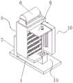
图1为本发明立体图;1 is a perspective view of the present invention;
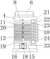
图2为本发明正面剖视图;Fig. 2 is the front sectional view of the present invention;
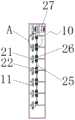
图3为本发明俯视剖面图;Fig. 3 is the top sectional view of the present invention;
图4为收缩机构剖视图;Figure 4 is a sectional view of a retraction mechanism;
图5为局部部件图;Figure 5 is a partial component diagram;
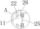
图6为图4中A处放大图。FIG. 6 is an enlarged view of part A in FIG. 4 .
图中:1底座、2立柱、3电动推杆、4箱体、5顶出机构、6出布轮、7 支撑架、8滑块、9凸块、10收放机构、11限位杆、12横板、13螺纹杆、14 滑道、15动力机构、16壳体、17固定组件、18布料挤压用电机、19连接杆、 20卡槽、21外壳、22主齿轮、23连接座、24弹簧、25联动杆、26侧齿齿轮、 27限位杆收放用电机、28固定块一、29螺栓、30螺纹座、31固定块二、32 固定座、33托板。In the picture: 1 base, 2 column, 3 electric push rod, 4 box body, 5 ejector mechanism, 6 cloth ejection wheel, 7 support frame, 8 slider, 9 bump, 10 retractable mechanism, 11 limit rod, 12 horizontal plate, 13 threaded rod, 14 slideway, 15 power mechanism, 16 casing, 17 fixed component, 18 motor for cloth extrusion, 19 connecting rod, 20 card slot, 21 shell, 22 main gear, 23 connecting seat, 24 springs, 25 linkage rods, 26 side gears, 27 limit rod retractable motors, 28 fixing
具体实施方式Detailed ways
下面通过附图和实施例对本发明作进一步详细阐述。The present invention will be described in further detail below through the accompanying drawings and embodiments.
本发明实施例提供一种纺织用叠布机,如图1-6所示,包括底座1,底座 1的顶部设置有立柱2。立柱2上安装有顶出机构5。顶出机构5包括电动推杆3、箱体4、支撑架7和横板12。箱体4安装在立柱2的上,箱体4的顶部设置有出布轮6。电动推杆3设置在箱体4内。支撑架7设置在电动推杆3的活动端。横板12设置在支撑架7上,横板12穿过箱体4并延伸至箱体4外。通过设置的多个横板12,可以一次性实现多个折叠操作,提高了该叠布机的叠布速度。An embodiment of the present invention provides a fabric stacker for textiles, as shown in Figures 1-6, comprising a
还包括收缩机构10,收缩机构10包括多个限位杆11、外壳21、多个主齿轮22、联动杆25、侧齿齿轮26和电机二27。外壳21设置在箱体4上。限位杆11垂直设置在外壳21的一侧,限位杆11的一端穿过外壳21并延伸至外壳21的另一侧。限位杆11的设置方向与横板12相平行。电机二27设置在外壳21内。各个主齿轮22对应套接在各个限位杆11表面,主齿轮22与电机二27的输出端啮合。侧齿齿轮26设置在主齿轮22的一侧且与限位杆11 套接,侧齿齿轮26和联动杆25相互啮合。各个主齿轮22通过联动杆25相互联动。通过设置的多个限位杆11的配合,可以有效的将布料固定住,防止在横板12顶出时,布料左右偏移的可能。同时各个限位杆11之间的间隔距离是测量过得,不会出现布料的破损的可能,同时限位杆11的表面是光滑的。这样大大减小布料和限位杆11之间的摩擦力,间接保护了布料本身。It also includes a
通过多个齿轮的配合,可以实现多个限位杆11同时移动,使得该装置的整体化和自动化大大提高,方便人们的使用。Through the cooperation of multiple gears,
收缩机构10还包括多个卡槽20。多个卡槽20等间距的分布在各个限位杆11表面。限位杆11通过卡槽20与主齿轮22啮合。限位杆11位于两个横板12之间。还包括连接座23和弹簧24。连接座23设置在11穿过21的一端,多个连接座23之间通过弹簧24相连。通过设置的弹簧24的连接,可以提高该限位杆11在工作时的稳定性,减小齿轮之间的震动次数,延长该装置的使用寿命。The
还包括用于压缩叠布之间空隙的动力机构15。动力机构15包括滑块8、螺纹杆13、壳体16、电机一18和多个用于放置叠好布料的托板33。壳体16 设置在底座1的上,电机一18设置在壳体16内。螺纹杆13的一端与电机一 18相连,滑块8设置在螺纹杆13上。多个托板33设置在壳体16的左右两侧。Also included is a
动力机构15还包括连接杆19、滑道14和凸块9。凸块9设置在滑块8 的底部。连接杆19的底部与电机一18的输出端相连,顶部与螺纹杆13相连。滑道14设置在外壳21上,滑块8滑动配合在滑道14上。通过设置的连接杆 19可以防止对布料压缩过大,使得布料出现不必要的折痕或者磨损,提高布料的品质。The
还包括固定组件17。固定组件17包括固定块一28、螺栓29、螺纹座30、固定块二31和固定座32。固定组件17设置在箱体4的底部,固定块二31与箱体4固定连接。固定块一28和固定块二31相接触,固定座32设置在固定块二31的侧面。螺纹座30设置在固定块一28的侧面,螺栓29穿过螺纹座 30并与固定座32螺纹连接。A fixing
工作原理:使用时,首先将布料从出布轮6中拽出,并平铺在箱体4上,通过固定组件17将布料一端固定住,再通过利用限位杆11将布料分成多个区域。通过将电动推杆3通电,使得横板12从箱体4内推出,使得布料成为凹凸状,再通过电机二27工作,通过主齿轮22、联动杆25和侧齿齿轮26的配合,使得限位杆11移动,布料利用重力下落堆叠,然后收回横板12并打开电机一18,通过旋转螺纹杆13,使得滑块8向下运动,最后从出布轮6减掉多余布料,将折叠好的布料放置好。Working principle: When using, first pull out the cloth from the
综上所述,该纺织用叠布机,通过设置的收缩机构10和顶出机构5的配合,将布料铺平在箱体4上,压上限位杆11,利用推出的横板12使得布料成凹凸状,收回横板12,在将滑块8向下压缩,使得布料堆叠完成,这样可以大大提高堆叠效率,一次可以堆叠完成,减少了工作时间,同时,通过滑块8 对布料进行挤压,可以减小布料之间的空隙距离,使得堆叠布料更加整齐和紧密,方便人们的搬运和使用,也节约了空间,可以方便工厂的保存,保障了工厂的利润。To sum up, this textile stacking machine, through the cooperation of the
尽管已经示出和描述了本发明的实施例,对于本领域的普通技术人员而言,可以理解在不脱离本发明的原理和精神的情况下可以对这些实施例进行多种变化、修改、替换和变型,本发明的范围由所附权利要求及其等同物限定。Although embodiments of the present invention have been shown and described, it will be understood by those skilled in the art that various changes, modifications, and substitutions can be made in these embodiments without departing from the principle and spirit of the invention and modifications, the scope of the present invention is defined by the appended claims and their equivalents.
Claims (7)
Translated fromChinesePriority Applications (1)
| Application Number | Priority Date | Filing Date | Title |
|---|---|---|---|
| CN201911111184.8ACN110844679B (en) | 2019-11-14 | 2019-11-14 | A textile stacker |
Applications Claiming Priority (1)
| Application Number | Priority Date | Filing Date | Title |
|---|---|---|---|
| CN201911111184.8ACN110844679B (en) | 2019-11-14 | 2019-11-14 | A textile stacker |
Publications (2)
| Publication Number | Publication Date |
|---|---|
| CN110844679Atrue CN110844679A (en) | 2020-02-28 |
| CN110844679B CN110844679B (en) | 2021-05-18 |
Family
ID=69600412
Family Applications (1)
| Application Number | Title | Priority Date | Filing Date |
|---|---|---|---|
| CN201911111184.8AActiveCN110844679B (en) | 2019-11-14 | 2019-11-14 | A textile stacker |
Country Status (1)
| Country | Link |
|---|---|
| CN (1) | CN110844679B (en) |
Cited By (1)
| Publication number | Priority date | Publication date | Assignee | Title |
|---|---|---|---|---|
| CN112374248A (en)* | 2020-10-07 | 2021-02-19 | 浙江美来亚纺织有限公司 | Lifting mechanism for folding prevention of textile stacking |
Citations (7)
| Publication number | Priority date | Publication date | Assignee | Title |
|---|---|---|---|---|
| EP0367881A1 (en)* | 1987-05-04 | 1990-05-16 | Jean-Baptiste Duribreux | Folding installation for a rectangular piece of textile |
| US5471817A (en)* | 1993-04-07 | 1995-12-05 | Automated Solutions Inc. | Bag folding system |
| US5493846A (en)* | 1993-04-07 | 1996-02-27 | Automated Solutions Inc. | Bag folding system |
| WO2004094190A2 (en)* | 2003-04-22 | 2004-11-04 | Key Safety Systems, Inc. | Airbag deployment sensor tape folding loom |
| CN202912483U (en)* | 2012-11-21 | 2013-05-01 | 儒拉玛特自动化技术(苏州)有限公司 | Folding device of air bag |
| CN104590640A (en)* | 2015-01-20 | 2015-05-06 | 上海东方久乐汽车安全气囊有限公司 | Automatic Z-shaped folding device for side curtain airbag |
| CN209455159U (en)* | 2018-11-28 | 2019-10-01 | 上海克拉方今环保科技有限公司 | A kind of folding towel structure of non-woven fabric |
- 2019
- 2019-11-14CNCN201911111184.8Apatent/CN110844679B/enactiveActive
Patent Citations (7)
| Publication number | Priority date | Publication date | Assignee | Title |
|---|---|---|---|---|
| EP0367881A1 (en)* | 1987-05-04 | 1990-05-16 | Jean-Baptiste Duribreux | Folding installation for a rectangular piece of textile |
| US5471817A (en)* | 1993-04-07 | 1995-12-05 | Automated Solutions Inc. | Bag folding system |
| US5493846A (en)* | 1993-04-07 | 1996-02-27 | Automated Solutions Inc. | Bag folding system |
| WO2004094190A2 (en)* | 2003-04-22 | 2004-11-04 | Key Safety Systems, Inc. | Airbag deployment sensor tape folding loom |
| CN202912483U (en)* | 2012-11-21 | 2013-05-01 | 儒拉玛特自动化技术(苏州)有限公司 | Folding device of air bag |
| CN104590640A (en)* | 2015-01-20 | 2015-05-06 | 上海东方久乐汽车安全气囊有限公司 | Automatic Z-shaped folding device for side curtain airbag |
| CN209455159U (en)* | 2018-11-28 | 2019-10-01 | 上海克拉方今环保科技有限公司 | A kind of folding towel structure of non-woven fabric |
Cited By (2)
| Publication number | Priority date | Publication date | Assignee | Title |
|---|---|---|---|---|
| CN112374248A (en)* | 2020-10-07 | 2021-02-19 | 浙江美来亚纺织有限公司 | Lifting mechanism for folding prevention of textile stacking |
| CN112374248B (en)* | 2020-10-07 | 2022-12-13 | 浙江美来亚纺织有限公司 | Lifting mechanism for folding prevention of textile stacking |
Also Published As
| Publication number | Publication date |
|---|---|
| CN110844679B (en) | 2021-05-18 |
Similar Documents
| Publication | Publication Date | Title |
|---|---|---|
| CN107855322B (en) | Bookshelf cleaning device | |
| CN111607949A (en) | Automatic folding machine and folding method | |
| CN111470328B (en) | A batch palletizing device for environmentally friendly flame retardant pressure-sensitive tapes | |
| CN110844679A (en) | A textile stacker | |
| CN108162496A (en) | A kind of vacuum compression bag cutting machine | |
| CN107475915A (en) | A kind of automatic collecting device, automatic material receiving method and sewing device | |
| CN111998622B (en) | Textile drying equipment | |
| CN209411479U (en) | A kind of cloth-pressing device of automatic cloth paving machine | |
| CN219280327U (en) | A cutting device equipped with auxiliary blade replacement | |
| CN114034175B (en) | Cotton thread drying device for textile industry | |
| CN214819278U (en) | Washboard grooving machine | |
| CN113862860B (en) | Blending regeneration cotton yarn presses cotton equipment | |
| CN211972750U (en) | A roller groove ironing machine | |
| CN210309274U (en) | Finished product braided bag ejection of compact collection device | |
| CN208792121U (en) | A kind of automatic slotting machine with waste recovery processing function | |
| CN220925847U (en) | A cloth conveying mechanism | |
| CN209701093U (en) | A head folding device for plastic bags | |
| CN221969190U (en) | A paperboard water-based printing device | |
| CN223060330U (en) | Feeding mechanism for clothing cleaning and cutting machine | |
| CN107927970A (en) | Hair products comb presses | |
| CN221441109U (en) | Clothing winding machine | |
| CN216611807U (en) | Orderly stacking machine for rubber hot-water bags | |
| CN217499636U (en) | Pleating processing device for fabric | |
| CN204162137U (en) | Chu Bu mechanism in composite material manufacturing and processing equipment | |
| CN217099028U (en) | Publication is compaction device for printing |
Legal Events
| Date | Code | Title | Description |
|---|---|---|---|
| PB01 | Publication | ||
| PB01 | Publication | ||
| SE01 | Entry into force of request for substantive examination | ||
| SE01 | Entry into force of request for substantive examination | ||
| GR01 | Patent grant | ||
| GR01 | Patent grant |