CN110841149A - Low-temperature locking automatic injector - Google Patents
Low-temperature locking automatic injectorDownload PDFInfo
- Publication number
- CN110841149A CN110841149ACN201911310001.5ACN201911310001ACN110841149ACN 110841149 ACN110841149 ACN 110841149ACN 201911310001 ACN201911310001 ACN 201911310001ACN 110841149 ACN110841149 ACN 110841149A
- Authority
- CN
- China
- Prior art keywords
- syringe
- sleeve
- groove
- flange
- sliding sleeve
- Prior art date
- Legal status (The legal status is an assumption and is not a legal conclusion. Google has not performed a legal analysis and makes no representation as to the accuracy of the status listed.)
- Pending
Links
Images


Classifications
- A—HUMAN NECESSITIES
- A61—MEDICAL OR VETERINARY SCIENCE; HYGIENE
- A61M—DEVICES FOR INTRODUCING MEDIA INTO, OR ONTO, THE BODY; DEVICES FOR TRANSDUCING BODY MEDIA OR FOR TAKING MEDIA FROM THE BODY; DEVICES FOR PRODUCING OR ENDING SLEEP OR STUPOR
- A61M5/00—Devices for bringing media into the body in a subcutaneous, intra-vascular or intramuscular way; Accessories therefor, e.g. filling or cleaning devices, arm-rests
- A61M5/178—Syringes
- A61M5/20—Automatic syringes, e.g. with automatically actuated piston rod, with automatic needle injection, filling automatically
- A61M5/2033—Spring-loaded one-shot injectors with or without automatic needle insertion
- A—HUMAN NECESSITIES
- A61—MEDICAL OR VETERINARY SCIENCE; HYGIENE
- A61M—DEVICES FOR INTRODUCING MEDIA INTO, OR ONTO, THE BODY; DEVICES FOR TRANSDUCING BODY MEDIA OR FOR TAKING MEDIA FROM THE BODY; DEVICES FOR PRODUCING OR ENDING SLEEP OR STUPOR
- A61M5/00—Devices for bringing media into the body in a subcutaneous, intra-vascular or intramuscular way; Accessories therefor, e.g. filling or cleaning devices, arm-rests
- A61M5/178—Syringes
- A61M5/31—Details
- A61M5/32—Needles; Details of needles pertaining to their connection with syringe or hub; Accessories for bringing the needle into, or holding the needle on, the body; Devices for protection of needles
- A61M5/3202—Devices for protection of the needle before use, e.g. caps
- A—HUMAN NECESSITIES
- A61—MEDICAL OR VETERINARY SCIENCE; HYGIENE
- A61M—DEVICES FOR INTRODUCING MEDIA INTO, OR ONTO, THE BODY; DEVICES FOR TRANSDUCING BODY MEDIA OR FOR TAKING MEDIA FROM THE BODY; DEVICES FOR PRODUCING OR ENDING SLEEP OR STUPOR
- A61M5/00—Devices for bringing media into the body in a subcutaneous, intra-vascular or intramuscular way; Accessories therefor, e.g. filling or cleaning devices, arm-rests
- A61M5/50—Devices for bringing media into the body in a subcutaneous, intra-vascular or intramuscular way; Accessories therefor, e.g. filling or cleaning devices, arm-rests having means for preventing re-use, or for indicating if defective, used, tampered with or unsterile
- A61M5/5013—Means for blocking the piston or the fluid passageway to prevent illegal refilling of a syringe
- A61M5/502—Means for blocking the piston or the fluid passageway to prevent illegal refilling of a syringe for blocking the piston
- A—HUMAN NECESSITIES
- A61—MEDICAL OR VETERINARY SCIENCE; HYGIENE
- A61M—DEVICES FOR INTRODUCING MEDIA INTO, OR ONTO, THE BODY; DEVICES FOR TRANSDUCING BODY MEDIA OR FOR TAKING MEDIA FROM THE BODY; DEVICES FOR PRODUCING OR ENDING SLEEP OR STUPOR
- A61M5/00—Devices for bringing media into the body in a subcutaneous, intra-vascular or intramuscular way; Accessories therefor, e.g. filling or cleaning devices, arm-rests
- A61M5/178—Syringes
- A61M5/20—Automatic syringes, e.g. with automatically actuated piston rod, with automatic needle injection, filling automatically
- A61M2005/2006—Having specific accessories
- A—HUMAN NECESSITIES
- A61—MEDICAL OR VETERINARY SCIENCE; HYGIENE
- A61M—DEVICES FOR INTRODUCING MEDIA INTO, OR ONTO, THE BODY; DEVICES FOR TRANSDUCING BODY MEDIA OR FOR TAKING MEDIA FROM THE BODY; DEVICES FOR PRODUCING OR ENDING SLEEP OR STUPOR
- A61M5/00—Devices for bringing media into the body in a subcutaneous, intra-vascular or intramuscular way; Accessories therefor, e.g. filling or cleaning devices, arm-rests
- A61M5/50—Devices for bringing media into the body in a subcutaneous, intra-vascular or intramuscular way; Accessories therefor, e.g. filling or cleaning devices, arm-rests having means for preventing re-use, or for indicating if defective, used, tampered with or unsterile
- A61M5/5013—Means for blocking the piston or the fluid passageway to prevent illegal refilling of a syringe
- A61M5/502—Means for blocking the piston or the fluid passageway to prevent illegal refilling of a syringe for blocking the piston
- A61M2005/5033—Means for blocking the piston or the fluid passageway to prevent illegal refilling of a syringe for blocking the piston by use of an intermediate blocking member positioned between the syringe barrel and the piston rod to prevent retraction of the latter, e.g. toothed clip placed on the piston rod
Landscapes
- Health & Medical Sciences (AREA)
- Vascular Medicine (AREA)
- Engineering & Computer Science (AREA)
- Anesthesiology (AREA)
- Biomedical Technology (AREA)
- Heart & Thoracic Surgery (AREA)
- Hematology (AREA)
- Life Sciences & Earth Sciences (AREA)
- Animal Behavior & Ethology (AREA)
- General Health & Medical Sciences (AREA)
- Public Health (AREA)
- Veterinary Medicine (AREA)
- Infusion, Injection, And Reservoir Apparatuses (AREA)
Abstract
Description
Translated fromChinese技术领域technical field
本发明涉及医疗器械领域,特别涉及一种低温锁定的自动注射设备。The invention relates to the field of medical instruments, in particular to a low temperature locking automatic injection device.
背景技术Background technique
现有的大部分自动注射器都要存放在5摄氏度左右用来保证药效。在注射前,自动注射器一般都要求在室温放30分钟或更长,这样有下列好处:Most existing auto-injectors are stored at around 5 degrees Celsius to ensure drug efficacy. Before injection, auto-injectors are generally required to stand at room temperature for 30 minutes or more, which has the following benefits:
1.在室温下注射,可以大大降低注射时的疼痛;1. Injection at room temperature can greatly reduce the pain during injection;
2.自动注射器是按室温下的药物粘度设计的,如果在低温下注射,自动注射器可能不工作或注射剂量不准确;2. The auto-injector is designed according to the drug viscosity at room temperature, if it is injected at low temperature, the auto-injector may not work or the injection dose is inaccurate;
3.药物的药效也是在室温下最有效。3. The efficacy of the drug is also most effective at room temperature.
而现在市场上所有的自动注射器,用户都可以在低温下注射。With all auto-injectors on the market today, users can inject at low temperatures.
CN110237366A公开了一种医用注射装置,包括外筒和笔帽,外筒的一端设置有可拆卸的药仓,药仓内设置有可更换的标准卡式药瓶,外筒的内部靠近药仓的一端设置有固定套,固定套的内部轴向移动设置有推杆座,推杆座的内部设置有可与传动杆的端部相啮合的传动环,传动杆的外侧套接有可轴向滑动的棘齿环,棘齿环的一端端面与外筒内部单向啮合,棘齿环的另一端轴向设置有第一弹簧,推杆座的一端轴向设置有与外筒顶住的推杆座弹簧,推杆的一端穿过推杆座伸入到标准卡式药瓶内与推块相连。CN110237366A discloses a medical injection device, including an outer cylinder and a pen cap, one end of the outer cylinder is provided with a detachable medicine storehouse, a replaceable standard cartridge medicine bottle is arranged in the medicine storey, and the inside of the outer tube is close to one end of the medicine storey A fixed sleeve is provided, the inner part of the fixed sleeve is axially moved with a push rod seat, the inside of the push rod seat is provided with a transmission ring that can be engaged with the end of the transmission rod, and the outer side of the transmission rod is sleeved with an axially slidable ring. Ratchet ring, one end face of the ratchet ring is unidirectionally engaged with the inside of the outer cylinder, the other end of the ratchet ring is axially provided with a first spring, and one end of the push rod seat is axially provided with a push rod seat which is withheld by the outer cylinder A spring, one end of the push rod extends through the push rod seat into the standard cartridge medicine bottle and is connected with the push block.
CN109999272A公开了一种用于胰岛素注射的一次性可调式注射装置,包括保护盖、一次性针头、笔芯套、主体外壳、笔芯和调节组件,所述主体外壳的一端设置有第二凸台,所述第二凸台的外部安装有笔芯套,所述笔芯套的一端开设有螺纹槽,所述第二凸台的外螺纹与螺纹槽相互螺接,所述笔芯套的另一端设置有第一凸台,所述第一凸台的外部通过螺纹连接有一次性针头,所述一次性针头的内部插接有钢针,所述笔芯套的内部安装有笔芯,所述笔芯套的外部套接有保护盖,所述主体外壳的另一端设置有调节组件,所述主体外壳的内部安装有固定套筒,所述固定套筒的一端向外凸出有凸缘部。CN109999272A discloses a disposable adjustable injection device for insulin injection, comprising a protective cover, a disposable needle, a refill cover, a main body shell, a refill and an adjustment assembly, and one end of the main body shell is provided with a second boss , a refill sleeve is installed on the outside of the second boss, one end of the refill sleeve is provided with a threaded groove, the external thread of the second boss is screwed with the threaded groove, and the other side of the refill sleeve is One end is provided with a first boss, the outside of the first boss is screwed with a disposable needle, the inside of the disposable needle is inserted with a steel needle, and the inside of the refill sleeve is installed with a refill, so The outer part of the refill sleeve is sleeved with a protective cover, the other end of the main body shell is provided with an adjustment component, the inside of the main body shell is installed with a fixed sleeve, and one end of the fixed sleeve is protruded with a flange department.
CN102264417A公开了一种注射设备,其包括:长的壳体;容器载运器,其具有药剂容器,针头安装到所述药剂容器;穿刺装置,其包括分离套管、预加载穿刺弹簧装置和穿刺保持装置,其中,所述预加载穿刺弹簧装置能够作用于所述分离套管且由此作用于所述容器载运器以使所述容器和针头做滑动运动,并且所述穿刺保持装置能够将所述穿刺弹簧装置保持在加载状态;注射装置,其包括柱塞杆、预加载注射弹簧装置和注射保持装置,其中,所述柱塞杆设置为作用在所述药剂容器中的限位器,所述预加载注射弹簧装置能够作用于所述柱塞杆而使得所述限位器在所述容器内产生位移,并且所述注射保持装置能够将所述注射弹簧装置保持在加载状态;退回装置,其包括预加载回缩弹簧和退回保持装置,其中,所述预加载回缩弹簧被布置为作用于所述分离套管且由此作用于所述容器载运器,并且所述退回保持装置能够将所述回缩弹簧保持在加载状态;穿刺序列启动装置,其能够作用于穿刺触发装置,所述穿刺触发装置被布置在所述分离套管上用于断开所述穿刺保持装置;注射触发装置,其设置在所述分离套管上并能够断开所述注射保持装置以当分离套管和柱塞杆移动到特定位置时启动注射序列;以及退回触发装置,其布置在所述分离套管上并能够在所述柱塞杆已经移动到一定位置时断开所述退回保持装置用于启动针头退回;其特征在于,所述设备还包括阻尼装置,所述阻尼装置包括隔室,该隔室包含一定体积的高粘性液体并且由所述柱塞杆的外表面和帽的内表面部分地限定,其中所述隔室布置有通道,所述液体仅在所述注射序列启动时被强制通过该通道,使得在所述隔室内的体积在整个注射序列期间随所述柱塞杆在所述容器的移动而减小,并由此产生阻尼剪切力。CN102264417A discloses an injection device comprising: an elongated housing; a container carrier having a medicament container to which a needle is mounted; a puncture device comprising a separation cannula, a preloaded puncture spring device and a puncture retention device, wherein the preloaded puncture spring means is capable of acting on the separation sleeve and thereby on the container carrier for sliding movement of the container and needle, and the puncture retention means is capable of holding the a puncture spring device is maintained in a loaded state; an injection device comprising a plunger rod, a preloaded injection spring device and an injection retention device, wherein the plunger rod is arranged to act as a stop in the medicament container, the preloaded injection spring means capable of acting on said plunger rod to displace said stop within said container, and said injection retention means capable of maintaining said injection spring means in a charged state; retraction means, which comprising a preloaded retraction spring and a retraction retention device, wherein the preloaded retraction spring is arranged to act on the separation sleeve and thereby the container carrier, and the retraction retention device is capable of placing all said retraction spring remains in a loaded state; puncture sequence activation means capable of acting on puncture trigger means arranged on said separation sleeve for disconnecting said puncture retention means; injection trigger means, it is provided on the separation sleeve and is capable of breaking the injection retention means to initiate an injection sequence when the separation sleeve and plunger rod are moved to a specific position; and a retraction trigger means arranged on the separation sleeve And can disconnect the retraction holding device for initiating needle retraction when the plunger rod has moved to a certain position; it is characterized in that the device further comprises a damping device, the damping device comprises a compartment, the compartment Contains a volume of highly viscous liquid and is partially defined by the outer surface of the plunger rod and the inner surface of the cap, wherein the compartment is arranged with a channel through which the liquid is forced only when the injection sequence is initiated. Channels such that the volume within the compartment decreases with movement of the plunger rod in the container during the entire injection sequence, and thereby generates damping shear forces.
发明内容SUMMARY OF THE INVENTION
本发明所要解决的技术问题是克服现有技术的不足,提供一种温控自动注射器,本发明的方案能保证自动注射器只有达到一定温度以上,才可以注射,其在低温下处于锁定状态,避免了用户因操作不当在低温下注射所带来的一系列弊端。The technical problem to be solved by the present invention is to overcome the deficiencies of the prior art and provide a temperature-controlled auto-injector. The solution of the present invention can ensure that the auto-injector can only be injected when the temperature is above a certain temperature. It eliminates a series of drawbacks caused by users injecting at low temperature due to improper operation.
为了实现以上目的,本发明提供了:In order to achieve the above object, the present invention provides:
一种低温锁定自动注射器,其特征在于,包括注射器本体、笔帽和记忆材料锁定件,所述注射器本体具有开口端,所述开口端和所述笔帽套接,所述注射器本体容纳预填充针筒,所述预填针筒的针头位于注射器本体和笔帽构成的空间中,所述笔帽和所述注射器本体通过所述记忆材料锁定件在低温下锁定,在高温下解锁;A low-temperature locking automatic injector, characterized in that it includes a syringe body, a pen cap and a memory material locking piece, the syringe body has an open end, the open end is sleeved with the pen cap, and the syringe body accommodates a prefilled syringe , the needle of the prefilled syringe is located in the space formed by the syringe body and the pen cap, and the pen cap and the syringe body are locked at low temperature by the memory material locking member, and unlocked at high temperature;
所述低温可根据药物的贮存要求进行选择,例如0-6度的任意温度,所述高温可根据药物的注射要求进行选择,例如10-25度的任意温度;The low temperature can be selected according to the storage requirements of the drug, such as any temperature of 0-6 degrees, and the high temperature can be selected according to the injection requirements of the drug, such as any temperature of 10-25 degrees;
所述记忆材料锁定件可以通过各种方式将笔帽和笔壳在低温下锁定,此处不做限定。The memory material locking member can lock the pen cap and the pen shell at low temperature in various ways, which are not limited here.
优选的,所述注射器本体的开口端具有第一凹槽,所述笔帽具有第二凹槽,当所述笔帽和所述注射器本体套接时,位于外层的部件上的凹槽为贯穿槽,且上述部件上的两个凹槽在位置上重叠,两个槽体重叠后形成一个深度为两者之和的槽体。此处不对笔帽和注射器本体套接时的内外关系做限定。Preferably, the open end of the syringe body has a first groove, the pen cap has a second groove, and when the pen cap and the syringe body are sleeved, the groove on the component on the outer layer is a through groove , and the two grooves on the above-mentioned components overlap in position, and the two groove bodies are overlapped to form a groove body whose depth is the sum of the two. The internal and external relationship between the cap and the syringe body is not limited here.
优选的,当所述笔帽和所述注射器本体套接时,所述记忆材料锁定件在低温下具有马氏体形状,该形状下,所述记忆材料锁定件卡入所述笔帽和所述注射器本体的凹槽,保持形状无法取出,锁定笔帽和注射器本体。至于马氏体的形状,不做特殊限定,只要该形状下,记忆材料锁定件具有大于第一凹槽和第二凹槽组成的凹槽深度的自由度,可以从上述凹槽中取出即可,例如,当所述套接部位为圆柱体时,记忆材料锁定件为半径(内径)大于套接部位半径的圆环。Preferably, when the pen cap and the syringe body are sleeved, the memory material locking member has a martensitic shape at low temperature, and under this shape, the memory material locking member is snapped into the pen cap and the syringe The groove of the body, which keeps the shape and cannot be taken out, locks the cap and the syringe body. As for the shape of the martensite, there is no special limitation, as long as the shape of the memory material locking member has a degree of freedom greater than the depth of the groove formed by the first groove and the second groove, and can be taken out from the above-mentioned groove. For example, when the socket connection part is a cylinder, the memory material locking member is a ring whose radius (inner diameter) is larger than the radius of the socket connection part.
所述记忆材料锁定件在高温下形变成奥氏体形状,该形状下,所述记忆材料锁定件从所述笔帽和所述注射器本体的凹槽中脱离并解锁笔帽和注射器本体。至于奥氏体的形状,不做特殊限定,只要该形状下,记忆材料锁定件具有小于第一凹槽和第二凹槽组成的凹槽深度的自由度,无法从上述凹槽中取出即可,例如,当所述套接部位为圆柱体时,记忆材料锁定件为短半径(内径)小于套接部位半径的椭圆形,或者短边(内径)小于套接部位半径的标准矩形或者四角为弧形的类矩形。The memory material lock is deformed at high temperature into an austenitic shape in which the memory material lock disengages from the groove of the cap and the syringe body and unlocks the cap and the syringe body. As for the shape of the austenite, there is no special limitation, as long as the memory material locking piece has a degree of freedom less than the depth of the groove formed by the first groove and the second groove, and cannot be taken out from the above-mentioned groove. For example, when the socket part is a cylinder, the memory material locking piece is an ellipse whose short radius (inner diameter) is smaller than the radius of the socket part, or a standard rectangle whose short side (inner diameter) is smaller than the radius of the socket part, or the four corners are Arc-like rectangle.
优选的,所述记忆材料为记忆合金。Preferably, the memory material is a memory alloy.
优选的,所述记忆合金选自镍钛合金、铜锌合金、铜铝镍合金、铜钼镍合金、铜金锌合金。Preferably, the memory alloy is selected from nickel-titanium alloy, copper-zinc alloy, copper-aluminum-nickel alloy, copper-molybdenum-nickel alloy, and copper-gold-zinc alloy.
本发明通过上述方案,能保证自动注射器只有达到一定温度以上,才可以注射,低于该温度时,笔帽和注射器本体无法分离,从而无法进行注射,避免了用户因操作不当在低温下注射所带来的一系列弊端。Through the above solution, the present invention can ensure that the automatic injector can only inject when the temperature is above a certain temperature. When the temperature is lower than the temperature, the pen cap and the injector body cannot be separated, so that the injection cannot be performed, and the user can be prevented from injecting at a low temperature due to improper operation. a series of disadvantages.
另一方面,本发明同时提供一种结构简单,零部件数量显著减少,且各注射步骤可靠性高的一次性自动注射器。On the other hand, the present invention also provides a disposable automatic injector with a simple structure, a significantly reduced number of parts, and high reliability in each injection step.
优选的,所述注射组件包括推进组件、启动组件和触发组件,所述推进组件位于启动组件中,所述推进组件包括推进部件和限位部件,推进部件通过和限位部件卡合实现限位,启动组件通过固定推进组件的限位形态确保推进组件在注射前的制动;Preferably, the injection assembly includes a propulsion assembly, an activation assembly and a trigger assembly, the propulsion assembly is located in the activation assembly, the propulsion assembly includes a propulsion part and a limit part, and the propulsion part is engaged with the limit part to realize the limit , the starting assembly ensures the braking of the propulsion assembly before injection by fixing the limit form of the propulsion assembly;
所述触发组件容纳所述预填充针筒,并在注射开始后,推动启动组件使其脱离制动位置。The trigger assembly accommodates the prefilled syringe and pushes the trigger assembly out of the detent position after injection has begun.
优选地,所述推进组件的推进部件包括主弹簧套和主弹簧,所述推进部件的限位部件包括主轴,所述启动组件包括启动滑套和辅助弹簧;Preferably, the propulsion component of the propulsion assembly includes a main spring sleeve and a main spring, the limiting component of the propulsion component includes a main shaft, and the activation assembly includes an activation sliding sleeve and an auxiliary spring;
所述主轴的轴体为中空,其一端封闭并具有第一凸缘,所述轴体上按照距离第一凸缘由近到远分别设有若干个具有弹性的第一凸块和第二凸块,所述第一凸块向轴体外表面方向凸起,其朝向第一凸缘方向具有轴向引导坡面,所述第二凸块向轴体内表面方向凸起,其朝向第一凸缘方向具有轴向引导坡面;The shaft body of the main shaft is hollow, one end of which is closed and has a first flange. The shaft body is respectively provided with a plurality of elastic first and second bumps according to the distance from the first flange to the farthest. , the first lug protrudes toward the outer surface of the shaft, and has an axial guide slope toward the first flange, and the second lug protrudes toward the inner surface of the shaft, toward the first flange Has an axial guide slope;
所述主弹簧套位于主轴轴体内,其一端封闭,另一端开放,所述封闭端可插进预填充针筒,所述主弹簧套的套体上设有和第二凸块匹配的卡槽,预紧的主弹簧一端抵住主弹簧套的封闭端,另一端抵住主轴的封闭端,所述第二凸块卡入卡槽中;The main spring sleeve is located in the shaft body of the main shaft, one end of which is closed and the other end is open, the closed end can be inserted into the pre-filled syringe, and the sleeve body of the main spring sleeve is provided with a slot matching the second projection. , one end of the preloaded main spring is pressed against the closed end of the main spring sleeve, and the other end is against the closed end of the main shaft, and the second protrusion is stuck into the slot;
所述启动滑套套接在所述主轴外,其远端具有第二凸缘,滑套内表面轴向开有可容纳第一凸块在其中滑动的第三凹槽,所述第三凹槽一端开口,另一端封闭,所述开口位于滑套的凸缘端,第一凸块和第二凸块完全位于所述启动滑套内部,所述第一凸缘和第二凸缘之间设有辅助弹簧,所述第一凸块卡在所述第三凹槽的封闭端;The starting sliding sleeve is sleeved outside the main shaft, and the distal end thereof has a second flange. The inner surface of the sliding sleeve is axially provided with a third groove for accommodating the sliding of the first protrusion in the third groove. One end is open and the other end is closed, the opening is located at the flange end of the sliding sleeve, the first protrusion and the second protrusion are completely located inside the starting sliding sleeve, and a setting is provided between the first flange and the second flange. There is an auxiliary spring, and the first bump is stuck at the closed end of the third groove;
主弹簧套的卡槽与主轴轴体的第二凸块卡合后,启动滑套的套体紧紧压住第二凸块,使得主轴轴体的第二凸块和主弹簧套的卡槽卡死,由此实现启动组件可靠地固定在锁止状态。After the slot of the main spring sleeve is engaged with the second bump of the spindle shaft body, the sleeve body of the starting sliding sleeve tightly presses the second bump, so that the second bump of the main shaft shaft body and the slot of the main spring sleeve jamming, thereby enabling the starter assembly to be reliably fixed in the locked state.
优选地,所述触发组件包括针筒滑套;Preferably, the trigger assembly comprises a syringe sleeve;
所述针筒滑套可以使预填充针筒在套内自由滑动,其套体上开有若干槽,所述针筒滑套的一端抵住启动滑套,另一端开设有所述注射器本体的第一凹槽,所述针筒滑套的长度超过预填充针筒的针头;The syringe sleeve can make the pre-filled syringe slide freely in the sleeve, the sleeve body is provided with a number of grooves, one end of the syringe sleeve is pressed against the start-up sleeve, and the other end is provided with the syringe body. the first groove, the length of the barrel sliding sleeve exceeds the needle head of the prefilled barrel;
优选地,所述壳体套设在所述自动注射器外部,其一端固定在第一凸缘上,另一端的长度短于预填充针筒的针头,壳体内部有若干卡块,所述卡块可穿过针筒滑套的贯穿槽卡住预填充针筒的凸缘,使预填充针筒无法朝注射方向移动。壳体另一端短于针头的长度决定了穿刺的深度;Preferably, the casing is sleeved on the outside of the automatic injector, one end of which is fixed on the first flange, and the other end is shorter than the needle of the pre-filled syringe. The block can pass through the through groove of the syringe sleeve to catch the flange of the pre-filled syringe, so that the pre-filled syringe cannot move toward the injection direction. The length of the other end of the shell shorter than the needle determines the depth of puncture;
优选地,所述第一和第二凸块所在的轴体壁部分镂空,形成具有弹性的长条;Preferably, the shaft wall part where the first and second bumps are located is hollowed out to form an elastic long strip;
优选地,所述第一和第二凸块的弹性长条位于一条直线时,所述第二凸块的长条宽度大于启动滑套内的第三凹槽的宽度,这样第二凸块的长条不会整体位于第三凹槽的空间内,确保启动滑套的内壁能够紧紧压住第二凸块;Preferably, when the elastic strips of the first and second protruding blocks are located in a straight line, the strip width of the second protruding block is larger than the width of the third groove in the starting sliding sleeve, so that the The long strip will not be located in the space of the third groove as a whole, so as to ensure that the inner wall of the starting sliding sleeve can tightly press the second bump;
优选地,所述主弹簧套的封闭端开孔,有利于主弹簧套和预填充针筒的活塞之间的空气及时排出,注射启动后,主弹簧套与活塞快速无障碍地接触;Preferably, the closed end of the main spring sleeve is open, which is conducive to the timely discharge of the air between the main spring sleeve and the piston of the pre-filled syringe, and after the injection is started, the main spring sleeve and the piston are in quick and unobstructed contact;
优选地,壳体和第一凸缘通过卡接固定;Preferably, the housing and the first flange are fixed by snap connection;
优选地,所述主轴的轴体上还设有若干个具有弹性的第三凸块,其向轴体外表面方向凸起,距离第一凸缘的距离大于第一和第二凸块。第三凸块的作用是便于装配,在主弹簧套和主弹簧装配在主轴上之前将启动滑套、和辅助弹簧临时固定在主轴上;Preferably, the shaft body of the main shaft is further provided with a plurality of elastic third protrusions, which protrude toward the outer surface of the shaft, and the distance from the first flange is greater than the first and second protrusions. The function of the third bump is to facilitate assembly, and temporarily fix the starting sliding sleeve and the auxiliary spring on the main shaft before the main spring sleeve and the main spring are assembled on the main shaft;
优选地,所述针筒滑套抵住启动滑套的一端具有向内凸起的倒钩。Preferably, one end of the needle cylinder sliding sleeve against the starting sliding sleeve has an inwardly protruding barb.
优选地,包括预填充针筒。Preferably, a pre-filled syringe is included.
本发明同时提供了一种利用上述注射器进行注射的方法,其特征在于,具体的步骤为:The present invention also provides a method for injection using the above-mentioned syringe, characterized in that the specific steps are:
步骤一:启动阶段,将注射器从低温状态中拿出,放置在高温状态下,直到注射器解锁后,将笔帽拔掉,将针筒滑套端放置在待注射皮肤上,并下压;Step 1: During the start-up phase, take the syringe out of the low temperature state and place it in a high temperature state until the syringe is unlocked, remove the cap, place the sleeve end of the syringe on the skin to be injected, and press down;
步骤二:穿刺阶段,针筒滑套推动启动滑套相对于针头向上运动,直到针头接触皮肤,继续施加压力,针头开始穿刺进入皮肤,针头滑套推动启动滑套继续向上运动,直到针头滑套完全进入壳体,此时到达预定的皮下刺穿深度,穿刺结束;在穿刺过程中,启动滑套下端运动至第二凸块之上,第二凸块和卡槽的锁死状态被解除,在主弹簧推力作用下,主弹簧套的卡槽沿着第二凸块的轴向引导坡面滑动,所述第二凸块向外弹性形变,直到卡槽完全离开第二凸块的卡合位置,主弹簧推动主弹簧套继续向前,主弹簧套的前部接触并抵住预填充针筒的活塞;Step 2: In the puncture stage, the needle sleeve pushes the starter sleeve to move upward relative to the needle until the needle touches the skin and continues to apply pressure. The needle begins to puncture into the skin, and the needle sleeve pushes the starter sleeve to continue to move upward until the needle slips. Completely enter the shell, and reach the predetermined subcutaneous piercing depth at this time, and the piercing is over; during the piercing process, start the lower end of the sliding sleeve to move above the second bump, and the locked state of the second bump and the slot is released. Under the thrust of the main spring, the slot of the main spring sleeve slides along the axial guide slope of the second bump, and the second bump is elastically deformed outward until the slot completely leaves the engagement of the second bump. position, the main spring pushes the main spring cover to continue forward, and the front of the main spring cover contacts and abuts the piston of the pre-filled syringe;
步骤三:注射阶段,预填充针筒和壳体卡合固定不动,主弹簧继续推动主弹簧套和活塞,将预填充针筒中的药物注射到病人皮下,直到活塞到达针筒最底端,注射结束;Step 3: In the injection stage, the pre-filled syringe and the housing are locked and fixed, the main spring continues to push the main spring cover and the piston, and the drug in the pre-filled syringe is injected into the patient's skin until the piston reaches the bottom of the syringe. injection ends;
步骤四:复位阶段,将自动注射器移开,辅助弹簧推动针头滑套和启动滑套回退,当启动滑套上端接触到所述第一凸块时,启动滑套上端沿着第一凸块的轴向引导坡面滑动,所述第一凸块向内弹性形变,随后从启动滑套中脱出,直到针筒滑套的倒钩卡住预填充针筒凸缘,注射程序结束。此时,第一凸块已经从启动滑套中脱出,且被封闭在壳体中,因不具有引导坡面,第一凸块无法反向重新进入启动滑套,注射者如果重复步骤一,整个注射过程将被卡止,避免了自动注射器的重复使用。Step 4: In the reset stage, move the automatic injector away, and the auxiliary spring pushes the needle sliding sleeve and the starting sliding sleeve to retreat. When the upper end of the starting sliding sleeve contacts the first bump, the upper end of the starting sliding sleeve moves along the first bump. The axial guide slope slides, and the first protruding block is elastically deformed inward, and then disengages from the starting sliding sleeve, until the barb of the sliding sleeve of the syringe catches the flange of the pre-filled syringe, and the injection procedure ends. At this point, the first bump has been disengaged from the starter sleeve and is enclosed in the housing. Because there is no guide slope, the first bump cannot re-enter the starter sleeve in the reverse direction. If the injector repeats
本发明相对于现有技术具有如下有益效果:The present invention has the following beneficial effects with respect to the prior art:
1、能保证自动注射器只有达到一定温度以上,才可以注射,低于该温度时,笔帽和壳体无法分离,从而无法进行注射,避免了用户因操作不当在低温下注射所带来的一系列弊端;1. It can ensure that the automatic injector can only inject when it reaches a certain temperature. When the temperature is lower than this temperature, the pen cap and the shell cannot be separated, so the injection cannot be performed, which avoids a series of problems caused by the user's improper operation at low temperature. disadvantages;
2、将注射器设计成推进组件、启动组件、触发组件和壳体,各部件互相配合,使整个注射器结构简单,零部件大幅减少;2. The syringe is designed as a propulsion assembly, a starter assembly, a trigger assembly and a housing, and the components cooperate with each other, so that the structure of the whole syringe is simple and the number of parts is greatly reduced;
3、推进部件通过和限位部件卡合实现限位,启动组件通过固定推进组件的限位形态确保推进组件在注射前的制动,实现注射前启动部件的可靠制动;3. The propulsion component realizes the limit by engaging with the limit component, and the starting component ensures the braking of the propulsion component before injection by fixing the limit shape of the propulsion component, and realizes the reliable braking of the starting component before injection;
4、第一凸块设计成具有单向的引导坡面,和启动滑套配合后能有效避免自动注射器的重复使用;4. The first bump is designed to have a one-way guide slope, which can effectively avoid the repeated use of the automatic injector after being matched with the starting sliding sleeve;
5、第二凸块设计成具有单向的引导坡面,和启动滑套配合后简单巧妙地实现推进组件的制动和推进状态的切换。5. The second bump is designed to have a one-way guiding slope, and after cooperating with the starting sliding sleeve, the braking of the propulsion assembly and the switching of the propulsion state can be realized simply and skillfully.
附图说明Description of drawings
下面结合附图,通过对本发明的具体实施方式详细描述,将使本发明的技术方案及其有益效果显而易见。The technical solutions of the present invention and its beneficial effects will be apparent through the detailed description of the specific embodiments of the present invention below in conjunction with the accompanying drawings.
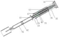
图1:本发明注射器各部件爆炸图;Fig. 1: exploded view of each component of the syringe of the present invention;
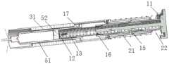
图2:本发明注射器装配状态内部结构剖面图;Figure 2: sectional view of the internal structure of the syringe of the present invention in an assembled state;
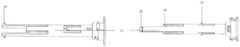
图3:本发明注射器主轴侧视图;Figure 3: side view of the main shaft of the syringe of the present invention;
图4:本发明注射器主弹簧套侧视图;Figure 4: side view of the main spring cover of the syringe of the present invention;
图5:本发明注射器启动滑套侧视图;Figure 5: side view of the present invention's syringe start sliding sleeve;
图6:本发明注射器针筒滑套侧视图;Figure 6: side view of the syringe barrel sliding sleeve of the present invention;
图7:本发明注射器推进组件和启动组件装配预固定状态图;Figure 7: The pre-fixed state diagram of the assembly of the syringe advancing assembly and the starting assembly of the present invention;
图8:本发明注射器推进组件和启动组件装配最终状态图;Figure 8: The final state diagram of the assembly of the syringe advancing assembly and the starting assembly of the present invention;
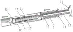
图9:本发明注射器装配状态内部结构剖面图;Figure 9: sectional view of the internal structure of the syringe of the present invention in an assembled state;
图10-14:本发明注射器注射过程图;Figure 10-14: the injection process diagram of the syringe of the present invention;
图15:本发明注射器笔帽和注射器本体分离状态图;Figure 15: The state diagram of the separation state of the syringe cap of the present invention and the syringe body;
图16:本发明注射器笔帽和注射器本体套接状态图;Figure 16: State diagram of socket connection between the syringe cap of the present invention and the syringe body;
图17:本发明记忆材料锁定件高低温形状图;Figure 17: high and low temperature shape diagram of the memory material locking piece of the present invention;
图18:本发明注射器笔帽和注射器本体锁定状态立体图;Figure 18: perspective view of the locked state of the syringe cap and the syringe body of the present invention;
图19:本发明注射器笔帽和注射器本体锁定状态剖视图;Figure 19: sectional view of the locked state of the syringe cap and the syringe body of the present invention;
图20:本发明注射器笔帽和注射器本体解锁状态剖视图。Figure 20: A cross-sectional view of the present invention's syringe cap and syringe body in an unlocked state.
图中部件编号如下:The part numbers in the figure are as follows:
1-注射器本体、11-主轴、12-主弹簧套、13-主弹簧、14-第一凸缘、15-第一凸块、16-第二凸块、17-卡槽、18-第三凸块、21-启动滑套、22-辅助弹簧、23-第二凸缘、24-第三凹槽、31-针筒滑套、32-贯穿槽、33-倒钩、34-第一凹槽、4-壳体、41-卡块、51-预填充针筒、52-活塞、53-针头保护套、54-笔帽、541-第二凹槽、55-预填充针筒凸缘、6-记忆材料锁定件、61-记忆材料锁定件马氏体形状、62-记忆材料锁定件奥氏体形状。1-syringe body, 11-spindle, 12-main spring sleeve, 13-main spring, 14-first flange, 15-first bump, 16-second bump, 17-card groove, 18-third Boss, 21-starting sleeve, 22-auxiliary spring, 23-second flange, 24-third groove, 31-syringe sleeve, 32-through groove, 33-barb, 34-first concave Slot, 4-housing, 41-block, 51-prefilled syringe, 52-piston, 53-needle protector, 54-pen cap, 541-second groove, 55-prefilled syringe flange, 6 - Memory material lock, 61 - Memory material lock martensitic shape, 62 - Memory material lock austenitic shape.
具体实施方式Detailed ways
下面将结合本发明实施例中的附图,对本发明实施例中的技术方案进行清楚、完整地描述,显然,所描述的实施例仅仅是本发明一部分实施例,而不是全部的实施例。基于本发明中的实施例,本领域技术人员在没有作出创造性劳动前提下所获得的所有其他实施例,都属于本发明保护的范围。The technical solutions in the embodiments of the present invention will be clearly and completely described below with reference to the accompanying drawings in the embodiments of the present invention. Obviously, the described embodiments are only a part of the embodiments of the present invention, but not all of the embodiments. Based on the embodiments of the present invention, all other embodiments obtained by those skilled in the art without creative efforts shall fall within the protection scope of the present invention.
实施例一:Example 1:
如图15-16所示,一种自动注射器,其包括注射器本体1和笔帽54,所述注射器本体1具有开口端,所述开口端和所述笔帽54套接,所述开口端具有第一凹槽34,所述笔帽54具有第二凹槽541,其为贯穿槽,所述笔帽54套接在所述注射器本体1的开头端上,且第一凹槽34和第二凹槽541在位置上重叠,两个槽体重叠后形成一个深度为两者之和的槽体。As shown in Figures 15-16, an automatic injector includes a
所述所述注射器本体1中容纳预填充针筒51(未示出),所述预填针筒51的针头位于注射器本体1和笔帽54构成的空间中。The
实施例二:Embodiment 2:
本实施例示出了记忆材料锁定件的制备。This example shows the preparation of a memory material lock.
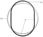
如图17所示,优选的,在变形条件下记忆材料锁定件具有在10-15℃的可逆的马氏体转变起始(As)温度,并在室温(Af)(15-25℃)完成马氏体向奥氏体的转变。对于所述记忆材料锁定件6的奥氏体形状62,这里不做特别限定,只要该形状下,记忆材料锁定件6具有大于第一凹槽34和第二凹槽541组成的凹槽深度的自由度,可以从上述凹槽中取出即可,例如,如图17所示的,半径(内径)大于笔帽54半径的圆形。As shown in Figure 17, preferably, the memory material lock has a reversible martensitic transformation initiation (As) temperature at 10-15°C under deformation conditions and is completed at room temperature (Af) (15-25°C) The transformation of martensite to austenite. The
通过在一小环境或冷冻温度,优选0-6℃,将所述记忆材料锁定件6拉伸制作成马氏体形状61,这里不做特别限定,只要该形状下,记忆材料锁定件6具有小于第一凹槽34和第二凹槽541组成的凹槽深度的自由度,无法从上述凹槽中取出即可,例如,如图17所示的,短半径(内径)小于笔帽54半径的椭圆形,或者短边(内径)小于笔帽54半径的标准矩形或者四角为弧形的类矩形。By stretching the memory
在本发明中较佳的记忆材料包括形状记忆合金。形状记忆合金存在于奥氏体状态和马氏体状态之中,在冷却时经历从奥氏体至马氏体的转变,在一较高温度Ms开始转变,终止在一较低温度Mf,加热状态时经历马氏体至奥氏体的转变,在一较低温度As开始转变,终止于一较高温度Af。Preferred memory materials in the present invention include shape memory alloys. Shape memory alloys exist in austenite state and martensite state, and undergo a transformation from austenite to martensite during cooling, starting at a higher temperature Ms, terminating at a lower temperature Mf, heating The state undergoes a transformation from martensite to austenite, starting at a lower temperature As and ending at a higher temperature Af.
形状记忆合金选自镍钛合金、铜锌合金、铜铝镍合金、铜钼镍合金、铜金锌合金,优选镍钛合金,制造镍钛合金和它们的三元的或四元的修改的成份的较佳合金材料包括二元合金和除了镍和钛之外含有一个或多个其它金属,例如一个或多个铁、钴、锰、铬、钒、钼、锆、铌、铪、钽、钨、铜、银、铂、钯、金和铝的合金。Shape memory alloys selected from nickel-titanium alloys, copper-zinc alloys, copper-aluminum-nickel alloys, copper-molybdenum-nickel alloys, copper-gold-zinc alloys, preferably nickel-titanium alloys, to make nickel-titanium alloys and their ternary or quaternary modified compositions Preferred alloying materials include binary alloys and those containing one or more other metals in addition to nickel and titanium, such as one or more of iron, cobalt, manganese, chromium, vanadium, molybdenum, zirconium, niobium, hafnium, tantalum, tungsten , copper, silver, platinum, palladium, gold and aluminum alloys.
一较佳的二元合金例子包括54.5%至56.0%、较佳地小于55.5%的镍和其余为钛,这是由于这成份范围的合金具有在环境温度上的可逆的马氏体转变(马氏体到奥氏体)温度。在整个本说明书中,关于合金成份所述的百分率都是在合金重量基础上的重量百分率。An example of a preferred binary alloy includes 54.5% to 56.0%, preferably less than 55.5% nickel and the remainder titanium, since alloys in this composition range have reversible martensitic transformation at ambient temperature (ma from tensite to austenite) temperature. Throughout this specification, the percentages stated with respect to alloy composition are weight percentages based on the weight of the alloy.
实施例三:Embodiment three:
如图18-20所示,为本发明所述自动注射器在低温储存状态下的锁定状态图以及高温状态下的解锁状态图,将注射器本体1的开口端和所述笔帽54套接后,对齐第一凹槽34和第二凹槽541,将处于奥氏体形状62的记忆材料锁定件6放置在第一凹槽34和第二凹槽541处,置于低温环境下,如图18-19所示,所述记忆材料锁定件6由奥氏体形状62转变为马氏体形状61,卡入第一凹槽34和第二凹槽541中,完成注射器的锁定。As shown in Figures 18-20, which are the locked state diagram of the auto-injector according to the present invention under the low temperature storage state and the unlocked state diagram under the high temperature state, after the open end of the
使用时,将锁定的注射器置于室温放置一段时间,所述记忆材料锁定件6由马氏体形状61转变为奥氏体形状62,并从第一凹槽34和第二凹槽541中脱离,完成注射器的解锁。When in use, the locked syringe is placed at room temperature for a period of time, and the memory
实施例四Embodiment 4
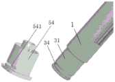
如图1-6所示,一种自动注射器,包括主轴11、主弹簧套12、主弹簧13、启动滑套21、辅助弹簧22、针筒滑套31、壳体4和预填充针筒51;As shown in FIGS. 1-6 , an automatic injector includes a
所述主轴11的轴体为中空,其一端封闭并具有第一凸缘14,所述轴体11上按照距离第一凸缘14由近到远分别设有若干个具有弹性的第一凸块15和第二凸块16,所述第一凸块15向轴体外表面方向凸起,其朝向第一凸缘14方向具有轴向引导坡面,所述第二凸块16向轴体内表面方向凸起,其朝向第一凸缘14方向具有轴向引导坡面;The shaft body of the
装配状态下,所述主弹簧套12位于主轴11轴体内,其一端封闭,另一端开放,所述封闭端可插进预填充针筒51,所述主弹簧套12的套体上设有和第二凸块匹配的卡槽17,预紧的主弹簧13一端抵住主弹簧套12的封闭端,另一端抵住主轴11的封闭端,所述第二凸块16卡入卡槽17中;In the assembled state, the
所述启动滑套21套接在所述主轴11外,其远端具有第二凸缘23,滑套内表面轴向开有可容纳第一凸块15在其中滑动的第三凹槽24,所述第三凹槽24一端开口,另一端封闭,所述开口位于启动滑套21具有凸缘的一端,第一凸块15和第二凸块16完全位于所述启动滑套21内部,所述第一凸缘14和第二凸缘之间设有辅助弹簧22,所述第一凸块15卡在所述第三凹槽的封闭端;The
主弹簧套12的卡槽17与主轴11轴体的第二凸块16卡合后,启动滑套21的套体紧紧压住第二凸块16,使得主轴11轴体的第二凸块16和主弹簧套12的卡槽卡死,使得主弹簧套12带着主弹簧13的预紧力可靠地固定在锁止状态;After the
所述针筒滑套31可以使预填充针筒51在套内自由滑动,其套体上开有若干贯穿槽32,所述针筒滑套31的一端抵住启动滑套21,另一端的长度超过预填充针筒51的针头,将预填充针筒51整体包裹在内部;针筒滑套31抵住启动滑套21的一端具有向内凸起的倒钩;所述预填充针筒51具有活塞52,优选地还可以具有针头保护套53;The
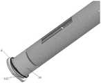
如图9所示,所述壳体4套设在所述自动注射器外部,其一端固定在第一凸缘14上,固定方式优选为卡接,另一端的长度短于预填充针筒51的针头,壳体4内部有若干卡块41,所述卡块41穿过针筒滑套31的贯穿槽32卡住预填充针筒51的凸缘,使预填充针筒51无法朝注射方向移动,壳体4另一端短于针头的长度决定了穿刺的深度;As shown in FIG. 9 , the housing 4 is sleeved on the outside of the automatic injector, one end of which is fixed on the
自动注射器还具有起保护作用的笔帽54,该笔帽54在使用时拔掉,当针头保护套53存在时,其和针头保护套53连接,拔掉笔帽54的同时拔掉针头保护套53。The auto-injector also has a
实施例五Embodiment 5
如图3所示,该实施例中,第一和第二凸块15、16所在的轴体壁部分镂空,形成具有弹性的长条,所述第一和第二凸块15、16位于长条上,当所述第一和第二凸块15、16的弹性长条位于一条直线时,所述第二凸块16的长条宽度大于启动滑套21内的第三凹槽24的宽度,这样第二凸块16的长条不会整体位于第三凹槽24的空间内,确保启动滑套21的内壁能够紧紧压住第二凸块16。As shown in FIG. 3 , in this embodiment, the wall of the shaft body where the first and
实施例六
该实施例中,所述主弹簧套12的封闭端开孔,有利于主弹簧套12和预填充针筒51的活塞之间的空气及时排出,注射启动后,主弹簧套12与活塞52快速无障碍地接触。In this embodiment, the closed end of the
实施例七Embodiment 7
如图7-8所示,该实施例中,所述主轴11的轴体上还设有若干个具有弹性的第三凸块18,其向轴体外表面方向凸起,距离第一凸缘14的距离大于第一和第二凸块15、16。第三凸块18的作用是便于装配,在主弹簧套12和主弹簧13装配在主轴11上之前将启动滑套21和辅助弹簧22临时固定在主轴11上。As shown in FIGS. 7-8 , in this embodiment, the shaft body of the
实施例八Embodiment 8
如图10-14所示,一种利用上述注射器进行注射的方法,具体的步骤为:As shown in Figures 10-14, a method of using the above-mentioned syringe for injection, the specific steps are:
步骤一:启动阶段,将注射器从低温状态中拿出,放置在高温状态下,直到注射器解锁后,将笔帽拔掉,将针筒滑套端放置在待注射皮肤上,并下压;;Step 1: During the start-up phase, take the syringe out of the low temperature state and place it in a high temperature state until the syringe is unlocked, remove the cap, place the sleeve end of the syringe on the skin to be injected, and press down;
步骤二:穿刺阶段,如图11所示,针筒滑套31推动启动滑套21相对于针头向上运动,直到针头接触皮肤,继续施加压力,针头开始穿刺进入皮肤,针头滑套31推动启动滑套21继续向上运动,直到针头滑套31完全进入壳体4,此时到达预定的皮下刺穿深度,穿刺结束;在穿刺过程中,启动滑套21的下端运动至第二凸块16之上,第二凸块16和卡槽17的锁死状态被解除,在主弹簧13推力作用下,主弹簧套12的卡槽17沿着第二凸块16的轴向引导坡面滑动,所述第二凸块16向外弹性形变,直到卡槽17完全离开第二凸块16的卡合位置,主弹簧13推动主弹簧套12继续向前,主弹簧套12的前部接触并抵住预填充针筒51的活塞52;Step 2: puncture stage, as shown in Figure 11, the
步骤三:注射阶段,如图12所示,预填充针筒51和壳体4卡合固定不动,主弹簧13继续推动主弹簧套12和活塞52,将预填充针筒51中的药物注射到病人皮下,直到活塞52到达预填充针筒51最底端,注射结束;Step 3: In the injection stage, as shown in FIG. 12 , the
步骤四:复位阶段,如图13-14所示,将自动注射器移开,辅助弹簧22推动针头滑套31和启动滑套21回退,当启动滑套21上端接触到所述第一凸块15时,启动滑套21上端沿着第一凸块15的轴向引导坡面滑动,所述第一凸块15向内弹性形变,随后从启动滑套21中脱出,直到针筒滑套31的倒钩33卡住预填充针筒凸缘55,注射程序结束。此时,第一凸块15已经从启动滑套21中脱出,且被封闭在壳体4中,因不具有引导坡面,第一凸块15无法反向重新进入启动滑套21,注射者如果重复步骤一,整个注射过程将被卡止,避免了自动注射器的重复使用。Step 4: In the reset stage, as shown in Figures 13-14, move the automatic injector away, the
以上所述仅为本发明的示例性实施例,并非因此限制本发明专利保护范围,凡是利用本发明说明书及附图内容所作的等效结构或等效流程变换,或直接或间接运用在其他相关的技术领域,均同理包括在本发明的专利保护范围内。The above descriptions are only exemplary embodiments of the present invention, and are not intended to limit the scope of patent protection of the present invention. Any equivalent structure or equivalent process transformation made by using the contents of the description and drawings of the present invention, or directly or indirectly applied to other related The technical fields of the present invention are similarly included in the scope of patent protection of the present invention.
Claims (10)
Priority Applications (2)
| Application Number | Priority Date | Filing Date | Title |
|---|---|---|---|
| CN201911310001.5ACN110841149A (en) | 2019-12-18 | 2019-12-18 | Low-temperature locking automatic injector |
| PCT/CN2020/122233WO2021120824A1 (en) | 2019-12-18 | 2020-10-20 | Automatic syringe locking at low temperatures |
Applications Claiming Priority (1)
| Application Number | Priority Date | Filing Date | Title |
|---|---|---|---|
| CN201911310001.5ACN110841149A (en) | 2019-12-18 | 2019-12-18 | Low-temperature locking automatic injector |
Publications (1)
| Publication Number | Publication Date |
|---|---|
| CN110841149Atrue CN110841149A (en) | 2020-02-28 |
Family
ID=69609816
Family Applications (1)
| Application Number | Title | Priority Date | Filing Date |
|---|---|---|---|
| CN201911310001.5APendingCN110841149A (en) | 2019-12-18 | 2019-12-18 | Low-temperature locking automatic injector |
Country Status (2)
| Country | Link |
|---|---|
| CN (1) | CN110841149A (en) |
| WO (1) | WO2021120824A1 (en) |
Cited By (5)
| Publication number | Priority date | Publication date | Assignee | Title |
|---|---|---|---|---|
| WO2021093503A1 (en)* | 2019-11-15 | 2021-05-20 | 苏州嘉树医疗科技有限公司 | Automatic syringe |
| WO2021120824A1 (en)* | 2019-12-18 | 2021-06-24 | 苏州嘉树医疗科技有限公司 | Automatic syringe locking at low temperatures |
| WO2021174669A1 (en)* | 2020-03-05 | 2021-09-10 | 苏州恒瑞宏远医疗科技有限公司 | Automatic injection device and method for using same |
| CN114534021A (en)* | 2022-04-25 | 2022-05-27 | 江苏万海医疗器械有限公司 | Quantitative liquid material conveying device and working method thereof |
| CN115025334A (en)* | 2022-06-09 | 2022-09-09 | 南京鈊帝医疗科技有限公司 | auto injector |
Families Citing this family (1)
| Publication number | Priority date | Publication date | Assignee | Title |
|---|---|---|---|---|
| US12005244B2 (en) | 2020-03-27 | 2024-06-11 | Medivena Sp. Z O.O. | Needle-based device based on direct wing-based coupling of a needle shield to a barrel thereof and safety mechanism implemented therein |
Citations (8)
| Publication number | Priority date | Publication date | Assignee | Title |
|---|---|---|---|---|
| US20100185148A1 (en)* | 2008-06-20 | 2010-07-22 | West Pharmaceutical Services, Inc. | Injector Apparatus |
| US20140236076A1 (en)* | 2011-05-12 | 2014-08-21 | Owen Mumford Limited | Injection devices |
| CN106470716A (en)* | 2014-06-03 | 2017-03-01 | 安姆根有限公司 | Controllable drug delivery systems and methods of use |
| US20170354791A1 (en)* | 2015-02-10 | 2017-12-14 | Gad Lewkonya | Safe auto-needle device |
| CN108434556A (en)* | 2018-05-23 | 2018-08-24 | 苏州鹏烨医疗科技有限公司 | Injection pen |
| WO2019011690A1 (en)* | 2017-07-12 | 2019-01-17 | Shl Medical Ag | ADMINISTRATION ASSEMBLY FOR A MEDICINE DELIVERY DEVICE AND DRUG DELIVERY DEVICE COMPRISING THE SAME |
| CN110520172A (en)* | 2017-04-19 | 2019-11-29 | 免疫医疗有限责任公司 | The automatic injector of electronics connection |
| CN211634672U (en)* | 2019-12-18 | 2020-10-09 | 苏州嘉树医疗科技有限公司 | Low-temperature locking automatic injector |
Family Cites Families (4)
| Publication number | Priority date | Publication date | Assignee | Title |
|---|---|---|---|---|
| GB0900930D0 (en)* | 2009-01-20 | 2009-03-04 | Future Injection Technologies Ltd | Injection device |
| WO2012164389A2 (en)* | 2011-06-02 | 2012-12-06 | Ucb Pharma S.A. | Auto-injector |
| MX2017006267A (en)* | 2014-11-18 | 2017-08-14 | Lilly Co Eli | Thermal locking mechanism for a medication delivery device. |
| CN110841149A (en)* | 2019-12-18 | 2020-02-28 | 苏州嘉树医疗科技有限公司 | Low-temperature locking automatic injector |
- 2019
- 2019-12-18CNCN201911310001.5Apatent/CN110841149A/enactivePending
- 2020
- 2020-10-20WOPCT/CN2020/122233patent/WO2021120824A1/ennot_activeCeased
Patent Citations (8)
| Publication number | Priority date | Publication date | Assignee | Title |
|---|---|---|---|---|
| US20100185148A1 (en)* | 2008-06-20 | 2010-07-22 | West Pharmaceutical Services, Inc. | Injector Apparatus |
| US20140236076A1 (en)* | 2011-05-12 | 2014-08-21 | Owen Mumford Limited | Injection devices |
| CN106470716A (en)* | 2014-06-03 | 2017-03-01 | 安姆根有限公司 | Controllable drug delivery systems and methods of use |
| US20170354791A1 (en)* | 2015-02-10 | 2017-12-14 | Gad Lewkonya | Safe auto-needle device |
| CN110520172A (en)* | 2017-04-19 | 2019-11-29 | 免疫医疗有限责任公司 | The automatic injector of electronics connection |
| WO2019011690A1 (en)* | 2017-07-12 | 2019-01-17 | Shl Medical Ag | ADMINISTRATION ASSEMBLY FOR A MEDICINE DELIVERY DEVICE AND DRUG DELIVERY DEVICE COMPRISING THE SAME |
| CN108434556A (en)* | 2018-05-23 | 2018-08-24 | 苏州鹏烨医疗科技有限公司 | Injection pen |
| CN211634672U (en)* | 2019-12-18 | 2020-10-09 | 苏州嘉树医疗科技有限公司 | Low-temperature locking automatic injector |
Cited By (7)
| Publication number | Priority date | Publication date | Assignee | Title |
|---|---|---|---|---|
| WO2021093503A1 (en)* | 2019-11-15 | 2021-05-20 | 苏州嘉树医疗科技有限公司 | Automatic syringe |
| WO2021120824A1 (en)* | 2019-12-18 | 2021-06-24 | 苏州嘉树医疗科技有限公司 | Automatic syringe locking at low temperatures |
| WO2021174669A1 (en)* | 2020-03-05 | 2021-09-10 | 苏州恒瑞宏远医疗科技有限公司 | Automatic injection device and method for using same |
| CN115379869A (en)* | 2020-03-05 | 2022-11-22 | 苏州恒瑞宏远医疗科技有限公司 | Automatic injection device and method of use thereof |
| CN114534021A (en)* | 2022-04-25 | 2022-05-27 | 江苏万海医疗器械有限公司 | Quantitative liquid material conveying device and working method thereof |
| CN114534021B (en)* | 2022-04-25 | 2022-08-16 | 江苏万海医疗器械有限公司 | Quantitative liquid material conveying device and working method thereof |
| CN115025334A (en)* | 2022-06-09 | 2022-09-09 | 南京鈊帝医疗科技有限公司 | auto injector |
Also Published As
| Publication number | Publication date |
|---|---|
| WO2021120824A1 (en) | 2021-06-24 |
Similar Documents
| Publication | Publication Date | Title |
|---|---|---|
| CN110841149A (en) | Low-temperature locking automatic injector | |
| CN107921214B (en) | Needle control and drug mixing systems for fluid delivery devices | |
| CN103889484B (en) | Injection device | |
| US6872190B1 (en) | Safety assembly for a syringe pre-filled with liquid, in particular a medicine | |
| RU2131748C1 (en) | Automatic or manual device for injections of liquid medicinal agent | |
| JP5938403B2 (en) | Safety devices for drug-filled syringes and injection devices | |
| US9446196B2 (en) | Auto-injector | |
| EP2114495B1 (en) | Safety shield system for a single use flexible-type compression syringe, and injection device | |
| CN110681004A (en) | an automatic injector | |
| JP6599359B2 (en) | Automatic injector | |
| TW200306873A (en) | Collapsible syringe cartridge | |
| EP1507566A1 (en) | Injection device with automatically retractable needle | |
| CN110072503B (en) | Integrated filling and injection caps for safety needle devices | |
| CN109982733B (en) | Implant/medicament injection system based on protective shell | |
| USRE48593E1 (en) | Auto-injector | |
| CN117942457A (en) | Syringe assembly for drug delivery | |
| CN110740771A (en) | Auto-injector with hollow plunger rod | |
| US20210196896A1 (en) | Injection Device | |
| CN212016369U (en) | Automatic injector | |
| CN211634672U (en) | Low-temperature locking automatic injector | |
| EP1961437B1 (en) | Instrument for injections with retractable needle following use | |
| JP7748542B2 (en) | Method for Assembling a Drug Delivery Device | |
| US12427258B2 (en) | Self-injector | |
| HK1184732B (en) | Safety device for a pre-filled syringe and injection device |
Legal Events
| Date | Code | Title | Description |
|---|---|---|---|
| PB01 | Publication | ||
| PB01 | Publication | ||
| SE01 | Entry into force of request for substantive examination | ||
| SE01 | Entry into force of request for substantive examination |