CN110840697A - A kind of joint auxiliary training device and method - Google Patents
A kind of joint auxiliary training device and methodDownload PDFInfo
- Publication number
- CN110840697A CN110840697ACN201911077349.4ACN201911077349ACN110840697ACN 110840697 ACN110840697 ACN 110840697ACN 201911077349 ACN201911077349 ACN 201911077349ACN 110840697 ACN110840697 ACN 110840697A
- Authority
- CN
- China
- Prior art keywords
- arm
- forearm
- fixing seat
- support
- small
- Prior art date
- Legal status (The legal status is an assumption and is not a legal conclusion. Google has not performed a legal analysis and makes no representation as to the accuracy of the status listed.)
- Pending
Links
- 238000000034methodMethods0.000titleclaimsabstractdescription13
- 210000000245forearmAnatomy0.000claimsabstractdescription138
- 230000007246mechanismEffects0.000claimsabstractdescription46
- 230000000903blocking effectEffects0.000claimsabstractdescription39
- 230000000694effectsEffects0.000claimsabstractdescription8
- 238000009434installationMethods0.000claimsdescription11
- 230000004888barrier functionEffects0.000claims1
- 238000005485electric heatingMethods0.000claims1
- 230000008901benefitEffects0.000description4
- 238000010586diagramMethods0.000description4
- 210000002310elbow jointAnatomy0.000description4
- 208000027418Wounds and injuryDiseases0.000description2
- 230000006378damageEffects0.000description2
- 230000004064dysfunctionEffects0.000description2
- 208000014674injuryDiseases0.000description2
- 206010062575Muscle contractureDiseases0.000description1
- 230000001464adherent effectEffects0.000description1
- 208000006111contractureDiseases0.000description1
- 230000006872improvementEffects0.000description1
- 210000000281joint capsuleAnatomy0.000description1
- 230000009916joint effectEffects0.000description1
- 210000003041ligamentAnatomy0.000description1
- 238000012986modificationMethods0.000description1
- 230000004048modificationEffects0.000description1
- 230000036407painEffects0.000description1
- 230000037325pain toleranceEffects0.000description1
- 230000002980postoperative effectEffects0.000description1
- 230000008569processEffects0.000description1
- 231100000241scarToxicity0.000description1
- 210000002435tendonAnatomy0.000description1
Images


Classifications
- A—HUMAN NECESSITIES
- A61—MEDICAL OR VETERINARY SCIENCE; HYGIENE
- A61H—PHYSICAL THERAPY APPARATUS, e.g. DEVICES FOR LOCATING OR STIMULATING REFLEX POINTS IN THE BODY; ARTIFICIAL RESPIRATION; MASSAGE; BATHING DEVICES FOR SPECIAL THERAPEUTIC OR HYGIENIC PURPOSES OR SPECIFIC PARTS OF THE BODY
- A61H1/00—Apparatus for passive exercising; Vibrating apparatus; Chiropractic devices, e.g. body impacting devices, external devices for briefly extending or aligning unbroken bones
- A61H1/02—Stretching or bending or torsioning apparatus for exercising
- A61H1/0274—Stretching or bending or torsioning apparatus for exercising for the upper limbs
- A—HUMAN NECESSITIES
- A61—MEDICAL OR VETERINARY SCIENCE; HYGIENE
- A61H—PHYSICAL THERAPY APPARATUS, e.g. DEVICES FOR LOCATING OR STIMULATING REFLEX POINTS IN THE BODY; ARTIFICIAL RESPIRATION; MASSAGE; BATHING DEVICES FOR SPECIAL THERAPEUTIC OR HYGIENIC PURPOSES OR SPECIFIC PARTS OF THE BODY
- A61H1/00—Apparatus for passive exercising; Vibrating apparatus; Chiropractic devices, e.g. body impacting devices, external devices for briefly extending or aligning unbroken bones
- A61H1/02—Stretching or bending or torsioning apparatus for exercising
- A61H1/0218—Drawing-out devices
- A61H1/0222—Traction tables
- A—HUMAN NECESSITIES
- A61—MEDICAL OR VETERINARY SCIENCE; HYGIENE
- A61H—PHYSICAL THERAPY APPARATUS, e.g. DEVICES FOR LOCATING OR STIMULATING REFLEX POINTS IN THE BODY; ARTIFICIAL RESPIRATION; MASSAGE; BATHING DEVICES FOR SPECIAL THERAPEUTIC OR HYGIENIC PURPOSES OR SPECIFIC PARTS OF THE BODY
- A61H1/00—Apparatus for passive exercising; Vibrating apparatus; Chiropractic devices, e.g. body impacting devices, external devices for briefly extending or aligning unbroken bones
- A61H1/02—Stretching or bending or torsioning apparatus for exercising
- A61H1/0274—Stretching or bending or torsioning apparatus for exercising for the upper limbs
- A61H1/0277—Elbow
Landscapes
- Health & Medical Sciences (AREA)
- Epidemiology (AREA)
- Pain & Pain Management (AREA)
- Physical Education & Sports Medicine (AREA)
- Rehabilitation Therapy (AREA)
- Life Sciences & Earth Sciences (AREA)
- Animal Behavior & Ethology (AREA)
- General Health & Medical Sciences (AREA)
- Public Health (AREA)
- Veterinary Medicine (AREA)
- Rehabilitation Tools (AREA)
Abstract
Translated fromChinese
Description
Translated fromChinese技术领域technical field
本发明涉及医疗器械技术领域,具体涉及一种关节辅助训练装置及方法。The invention relates to the technical field of medical devices, in particular to a joint auxiliary training device and method.
背景技术Background technique
肘关节遭受严重损伤时,术后肘关节屈曲功能障碍一般要经过长达两个月以上的时间才能康复。治疗肘关节屈曲功能障碍主要是通过被动活动和关节牵引的方法进行康复,以便牵伸粘连的瘢痕组织及挛缩的关节囊和韧带等,进而达到恢复关节活动的目的。传统康复训练是由医务人员或者家人在治疗过程中穿插进行强制性活动肘关节,即用手反复用力伸屈手臂,迫使肘关节活动,以确保肌腱与肘关节的正常康复,现有的肘关节康复训练装置不可调节训练强度,患者的伤势和伤痛的承受能力也不尽相同,操作不当则易造成二次伤害,增加患者的痛苦。When the elbow joint is seriously injured, the postoperative elbow flexion dysfunction generally takes more than two months to recover. The treatment of elbow flexion dysfunction is mainly through passive movement and joint traction for rehabilitation, in order to stretch the adherent scar tissue and contracture joint capsule and ligament, etc., and then achieve the purpose of restoring joint activity. Traditional rehabilitation training is interspersed by medical staff or family members to perform mandatory elbow movement during the treatment process, that is, the arm is repeatedly stretched and flexed with the hand to force the elbow joint to move, so as to ensure the normal rehabilitation of the tendon and the elbow joint. The rehabilitation training device cannot adjust the training intensity, and the patient's injury and pain tolerance are not the same. Improper operation may easily cause secondary injury and increase the patient's pain.
发明内容SUMMARY OF THE INVENTION
本发明所要解决的技术问题是提供一种关节辅助训练装置及方法,功能齐全,方便调节训练强度,以解决现有技术中的问题。The technical problem to be solved by the present invention is to provide a joint auxiliary training device and method with complete functions and convenient adjustment of training intensity, so as to solve the problems in the prior art.
为解决上述技术问题,本发明的技术方案是:一种关节辅助训练装置,包括底板,所述底板上固定安装有大臂固定座,所述大臂固定座上转动安装有小臂支架,所述小臂支架上活动安装有小臂固定座,所述小臂支架和所述小臂固定座之间设有小臂固定座锁定机构,所述底座上设有小臂固定座牵引机构,所述底座上还设有小臂支架转动限位机构。In order to solve the above technical problems, the technical solution of the present invention is: a joint auxiliary training device, comprising a bottom plate, a big arm fixing seat is fixedly installed on the bottom plate, and a small arm bracket is rotatably installed on the big arm fixing seat, so A forearm fixing seat is movably installed on the forearm bracket, a forearm fixing seat locking mechanism is arranged between the forearm bracket and the forearm fixing seat, and a forearm fixing seat pulling mechanism is arranged on the base, so The base is also provided with a forearm bracket rotation limiting mechanism.
作为优选的技术方案,所述小臂支架包括相对设置在所述大臂固定座的前后两侧的两个支撑臂,所述支撑臂的一端转动安装在所述大臂固定座上,所述支撑臂转动的轴线前后延伸;两个所述支撑臂的内侧设有沿所述支撑臂的长度方向延伸的滑道,两个所述滑道之间滑动安装有所述小臂固定座;所述支撑臂的外侧固定安装有辅助把手;两个所述支撑臂远离所述大臂固定座的一端还固定安装有一个连接板。As a preferred technical solution, the forearm bracket includes two support arms oppositely arranged on the front and rear sides of the big arm fixing seat, one end of the supporting arms is rotatably mounted on the big arm fixing seat, and the The axis of rotation of the support arm extends forward and backward; the inner side of the two support arms is provided with a slideway extending along the length direction of the support arm, and the forearm fixing seat is slidably installed between the two slideways; An auxiliary handle is fixedly installed on the outer side of the support arm; a connecting plate is also fixedly installed at one end of the two support arms away from the big arm fixing seat.
作为优选的技术方案,所述小臂固定座锁定机构包括位于所述小臂固定座的前后两侧的螺纹孔,所述支撑臂的外侧设有连通所述滑道的长条形孔,所述长条形孔的长度方向沿所述支撑臂的长度方向延伸;还包括锁紧螺栓,所述锁紧螺栓的一端穿过所述长条形孔并旋合在所述螺纹孔内。As a preferred technical solution, the locking mechanism of the forearm fixing seat includes threaded holes located on the front and rear sides of the forearm fixing seat, and the outer side of the support arm is provided with a long strip hole that communicates with the slideway, so The longitudinal direction of the elongated hole extends along the longitudinal direction of the support arm; and a locking bolt is further included, one end of the locking bolt passes through the elongated hole and is screwed into the threaded hole.
作为优选的技术方案,所述牵引机构包括固定安装在所述底板上的支撑轮,所述支撑轮位于所述小臂支架的左侧,还包括牵引绳,所述牵引绳的一端连接有挂钩,所述小臂固定座上设有挂环,所述牵引绳的另一端绕过所述支撑轮向下延伸并连接有负重块,所述连接板上设有过线槽。As a preferred technical solution, the traction mechanism includes a support wheel that is fixedly installed on the bottom plate, the support wheel is located on the left side of the forearm bracket, and also includes a traction rope, one end of which is connected with a hook , the forearm fixing seat is provided with a hanging ring, the other end of the traction rope extends downward around the support wheel and is connected with a weight block, and the connecting plate is provided with a wire slot.
作为优选的技术方案,所述小臂支架转动限位机构置包括固定安装在所述支撑臂的外侧的凸块,所述底板上固定安装有位于所述支撑臂的外侧的辅助板,所述辅助板上转动安装有与所述凸块相匹配的阻挡臂,所述阻挡臂转动的轴线与所述支撑臂转动的轴线重合,所述阻挡臂位于所述凸块的顺时针方位,所述阻挡臂与所述辅助板之间设有角度调节机构。As a preferred technical solution, the position of the forearm bracket rotation limiting mechanism includes a convex block fixedly installed on the outer side of the support arm, an auxiliary plate located on the outer side of the support arm is fixedly installed on the bottom plate, and the The auxiliary plate is rotatably installed with a blocking arm matching the projection, the axis of rotation of the blocking arm coincides with the axis of rotation of the support arm, the blocking arm is located in the clockwise direction of the projection, the An angle adjustment mechanism is arranged between the blocking arm and the auxiliary plate.
作为优选的技术方案,所述阻挡臂的一端设有避让槽,所述辅助板位于所述避让槽内,所述避让槽内还固定安装有前后延伸的转动轴,所述阻挡臂通过所述转动轴转动安装在所述辅助板上;所述辅助板呈半圆形,所述辅助板的轴线与所述转动轴的轴线重合。As a preferred technical solution, one end of the blocking arm is provided with an escape groove, the auxiliary plate is located in the escape groove, and a rotating shaft extending front and rear is also fixedly installed in the escape groove, and the blocking arm passes through the escape groove. The rotating shaft is rotatably mounted on the auxiliary plate; the auxiliary plate is semicircular, and the axis of the auxiliary plate coincides with the axis of the rotating shaft.
作为优选的技术方案,所述角度调节机构包括位于所述阻挡臂内的安装腔,所述安装腔设有向着所述转动轴延伸并连通所述避让槽的通孔,所述通孔内活动安装有限位销,所述辅助板上设有多个与所述限位销相匹配的限位槽;所述限位销的一端固定安装有位于所述安装腔内的挡板,所述挡板远离所述转动轴的一侧与所述安装腔之间设有弹簧;所述挡板远离所述转动轴的一侧还固定安装有沿所述阻挡臂的长度方向延伸的拉杆,所述阻挡臂上设有供所述拉杆穿出的过孔,所述拉杆上固定安装有位于所述阻挡臂的外侧的拉块。As a preferred technical solution, the angle adjustment mechanism includes an installation cavity located in the blocking arm, the installation cavity is provided with a through hole extending toward the rotating shaft and communicating with the escape groove, and the through hole is movable in the through hole A limit pin is installed, and the auxiliary plate is provided with a plurality of limit grooves that match the limit pins; one end of the limit pin is fixedly installed with a baffle plate located in the installation cavity, and the baffle plate is located in the installation cavity. A spring is arranged between the side of the plate away from the rotating shaft and the installation cavity; the side of the baffle plate away from the rotating shaft is also fixedly installed with a pull rod extending along the length direction of the blocking arm. The blocking arm is provided with a through hole for the pull rod to pass through, and a pull block located on the outer side of the blocking arm is fixedly installed on the pull rod.
作为进一步的改进,所述辅助板上设有与所述凸块相匹配的滑槽,所述凸块与所述滑槽的端部相抵时,所述支撑臂水平向左延伸或水平向右延伸。As a further improvement, the auxiliary plate is provided with a chute matching the protrusion, and when the protrusion is in contact with the end of the chute, the support arm extends horizontally to the left or horizontally to the right extend.
一种利所述的一种关节辅助训装置的关节辅助训练方法,该方法包含以下步骤:A joint auxiliary training method of the described joint auxiliary training device, the method comprises the following steps:
S1,调节所述小臂支架转动限位机构,限制所述小臂支架可在较小的角度内范围转动。S1, adjust the rotation limiting mechanism of the forearm bracket to limit the rotation of the forearm bracket within a small angle range.
S2,根据使用者手臂长度调节所述小臂固定座位置,然后通过所述小臂固定座锁定机构将所述小臂固定座锁定在所述小臂支架上,并将损伤手臂的大臂置于所述大臂固定座内、小臂置于所述小臂固定座内。S2, adjust the position of the forearm fixing seat according to the length of the user's arm, then lock the forearm fixing seat on the forearm bracket through the forearm fixing seat locking mechanism, and place the forearm of the injured arm on the forearm bracket In the big arm fixing seat, the small arm is placed in the small arm fixing seat.
S3,通过未损伤手臂拉动所述辅助把手带动所述小臂支架转动,进行被动活动训练。S3 , the forearm bracket is driven to rotate by pulling the auxiliary handle by the uninjured arm to perform passive activity training.
S4,调节所述小臂支架转动限位机构,使所述小臂支架的可转动范围增大,并重复S3。S4, adjust the rotation limit mechanism of the forearm support to increase the rotatable range of the forearm support, and repeat S3.
S5,通过调节所述小臂固定座锁定机构解除对所述小臂固定座的锁定,然后将所述小臂固定座与所述小臂固定座牵引机构连接,进行关节牵引训练。S5 , releasing the locking of the forearm fixing seat by adjusting the locking mechanism of the forearm fixing seat, and then connecting the forearm fixing seat with the traction mechanism of the forearm fixing seat to perform joint traction training.
由于采用了上述技术方案,一种关节辅助训练装置及其方法,包括底板,所述底板上固定安装有大臂固定座,所述大臂固定座上转动安装有小臂支架,所述小臂支架上活动安装有小臂固定座,所述小臂支架和所述小臂固定座之间设有小臂固定座锁定机构,所述底座上设有小臂固定座牵引机构,所述底座上还设有小臂支架转动限位机构;本发明方便根据使用者的手臂长短,通过滑动小臂固定座以调节大臂固定座和小臂固定座之间的距离,具有适用性好的优点;本发明通过将小臂固定座锁定在小臂支架上,然后通过拉动辅助把手带动小臂支架转动,进行被动活动训练,或者通过解除对小臂固定座的锁定,将挂钩连接在挂环上,负重块通过牵引绳向左拉动小臂固定座,小臂固定座向左拉动小臂,进行关节牵引训练,具有功能齐全的优点;本发明通过不断调节阻挡臂使小臂支架可转动角度逐渐增大,即进行被动活动训练时,小臂转动的范围逐渐增大,以逐渐曾加训练强度,具有方便调节的优点。Due to the adoption of the above technical solutions, a joint auxiliary training device and method thereof include a base plate, a large arm fixing seat is fixedly installed on the base plate, a forearm bracket is rotatably installed on the big arm fixing seat, and the forearm A forearm fixing seat is movably installed on the bracket, a forearm fixing seat locking mechanism is arranged between the forearm bracket and the forearm fixing seat, a forearm fixing seat pulling mechanism is arranged on the base, and a forearm fixing seat pulling mechanism is arranged on the base. A forearm bracket rotation limiting mechanism is also provided; the present invention is convenient to adjust the distance between the forearm fixed seat and the forearm fixed seat by sliding the forearm fixed seat according to the length of the user's arm, and has the advantages of good applicability; The present invention performs passive activity training by locking the forearm fixing seat on the forearm support, and then driving the forearm support to rotate by pulling the auxiliary handle, or connecting the hook on the hanging ring by releasing the locking of the forearm fixing seat, The weight-bearing block pulls the forearm fixing seat to the left through the traction rope, and the forearm fixing seat pulls the forearm to the left to perform joint traction training, which has the advantage of complete functions; the present invention continuously adjusts the blocking arm so that the rotation angle of the forearm bracket gradually increases Large, that is, during passive activity training, the range of forearm rotation is gradually increased to gradually increase the training intensity, which has the advantage of convenient adjustment.
附图说明Description of drawings
为了更清楚地说明本发明实施例或现有技术中的技术方案,下面将对实施例或现有技术描述中所需要使用的附图作简单地介绍,显而易见地,下面描述中的附图仅仅是本发明的一些实施例,对于本领域普通技术人员来讲,在不付出创造性劳动性的前提下,还可以根据这些附图获得其他的附图。In order to explain the embodiments of the present invention or the technical solutions in the prior art more clearly, the following briefly introduces the accompanying drawings that need to be used in the description of the embodiments or the prior art. Obviously, the accompanying drawings in the following description are only These are some embodiments of the present invention, and for those of ordinary skill in the art, other drawings can also be obtained from these drawings without any creative effort.
图1是本发明实施例的结构示意图;1 is a schematic structural diagram of an embodiment of the present invention;
图2是图1的俯视示意图;Fig. 2 is the top schematic view of Fig. 1;
图3是本发明实施例的滑道的结构示意图;3 is a schematic structural diagram of a slideway according to an embodiment of the present invention;
图4是本发明实施例的小臂固定座锁定机构的结构示意图;4 is a schematic structural diagram of a forearm fixing seat locking mechanism according to an embodiment of the present invention;
图5是图1中Ⅰ部分的剖视图;Fig. 5 is the sectional view of part I in Fig. 1;
图6是图5中Ⅱ部分的剖视图;Fig. 6 is the sectional view of II part in Fig. 5;
图7是本发明实施例的阻挡臂的结构示意图;7 is a schematic structural diagram of a blocking arm according to an embodiment of the present invention;
图8是本发明实施例的一种关节辅助训练方法的流程图。FIG. 8 is a flowchart of a joint auxiliary training method according to an embodiment of the present invention.
图中:1-底板;2-大臂固定座;3-小臂支架;301-支撑臂;302-辅助把手;303-连接板;4-小臂固定座;401-手握把;5-滑道;6-螺纹孔;7-长条形孔;8-锁紧螺栓;9-支撑轮;10-牵引绳;11-挂钩;12-挂环;13-负重块;14-凸块;15-辅助板;16-阻挡臂;17-避让槽;18-转动轴;19-安装腔;20-通孔;21-限位销;22-限位槽;23-挡板;24-弹簧;25-拉杆;26-过孔;27-拉块;28-滑槽;29-绑带。In the picture: 1- bottom plate; 2- big arm fixing seat; 3- forearm bracket; 301- supporting arm; 302- auxiliary handle; 303- connecting plate; 4- forearm fixing seat; 401- hand grip; 5- Slideway; 6-threaded hole; 7-long strip hole; 8-locking bolt; 9-support wheel; 10-traction rope; 11-hook; 12-hanging ring; 13-weight block; 14-protrusion; 15-auxiliary plate; 16-blocking arm; 17-avoidance groove; 18-rotating shaft; 19-installation cavity; 20-through hole; 21-limit pin; 22-limit slot; 23-baffle plate; 24-spring ; 25-tie rod; 26-through hole; 27-pull block; 28-chute; 29-strap.
具体实施方式Detailed ways
如图1至图7所示,一种关节辅助训练装置,包括底板1,所述底板1上固定安装有大臂固定座2,所述大臂固定座2上转动安装有小臂支架3,所述小臂支架3上活动安装有小臂固定座4,所述大臂固定座2和所述小臂固定座3上均设有用于放置手臂的弧形槽,且所述弧形槽的前后两侧设有绑带29,所述小臂固定座4的弧形槽内还固定安装有手握把401;所述小臂支架3和所述小臂固定座4之间设有小臂固定座锁定机构,所述底座1上设有小臂固定座牵引机构,所述底座1上还设有小臂支架转动限位机构。As shown in FIG. 1 to FIG. 7 , a joint auxiliary training device includes a base plate 1, a large
所述小臂支架3包括相对设置在所述大臂固定座2的前后两侧的两个支撑臂301,所述支撑臂301的一端转动安装在所述大臂固定座2上,所述支撑臂301转动的轴线前后延伸;两个所述支撑臂301的内侧设有沿所述支撑臂301的长度方向延伸的滑道5,两个所述滑道5之间滑动安装有所述小臂固定座4,方便根据使用者的手臂长短,通过滑动小臂4固定座以调节大臂固定座2和小臂固定座4之间的距离;所述支撑臂301的外侧固定安装有辅助把手302,方便通过拉动辅助把手302带动小臂支架3转动;两个所述支撑臂301远离所述大臂固定座2的一端还固定安装有一个连接板303,用以加固两个支撑臂301之间的连接。The
具体的,所述小臂固定座锁定机构包括位于所述小臂固定座4的前后两侧的螺纹孔6,所述支撑臂301的外侧设有连通所述滑道5的长条形孔7,所述长条形孔7的长度方向沿所述支撑臂301的长度方向延伸;还包括锁紧螺栓8,所述锁紧螺栓8的一端穿过所述长条形孔7并旋合在所述螺纹孔6内。通过旋紧缩紧螺栓8将小臂固定座4锁定在小臂支架3上,使小臂固定座4不可在滑道5内移动;或者松动缩紧螺栓8解除对小臂固定座4的锁定,使小臂固定座4可在滑道5内移动。Specifically, the locking mechanism of the forearm fixing seat includes threaded
使用时,首先根据使用者手臂长度调节所述小臂固定座4位置,通过滑动小臂4固定座以调节大臂固定座2和小臂固定座4之间的距离,调节完毕后,通过旋紧锁紧螺栓8将小臂固定座4锁定在小臂支架3上,使小臂固定座4不可在滑道5内移动;然后将损伤手臂的大臂置于所述大臂固定座内2、小臂置于所述小臂固定座内4,并通过绑带进行固定,然后通过未损伤手臂拉动所述辅助把手302带动所述小臂支架3转动,小臂支架3带动小臂固定座4转动,小臂固定座4带动小臂转动使肘关节弯曲,进行被动活动训练。When in use, first adjust the position of the
所述牵引机构包括固定安装在所述底板1上的支撑轮9,所述支撑轮9位于所述小臂支架3的左侧,还包括牵引绳10,所述牵引绳10的一端连接有挂钩11,所述小臂固定座4上设有挂环12,所述牵引绳10的另一端绕过所述支撑轮9向下延伸并连接有负重块13,所述连接板303上设有过线槽。当进行被动活动训练时,需将牵引绳10从小臂固定座4取下,以减轻转动小臂支架3时的负担;或者通过松动缩紧螺栓8解除对小臂固定座4的锁定,此时小臂固定座4可在滑道5内移动,将挂钩11连接在挂环12上,负重13块通过牵引绳10向左拉动小臂固定座4,小臂固定座4向左拉动小臂,进行关节牵引训练。The traction mechanism includes a
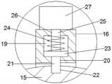
所述小臂支架转动限位机构置包括固定安装在所述支撑臂301的外侧的凸块14,所述底板1上固定安装有位于所述支撑臂301的外侧的辅助板15,所述辅助板15上转动安装有与所述凸块14相匹配的阻挡臂16,所述阻挡臂16转动的轴线与所述支撑臂301转动的轴线重合,所述阻挡臂16位于所述凸块14的顺时针方位,所述阻挡臂16与所述辅助板15之间设有角度调节机构。当小臂支架3转动时带动凸块14转动,通过阻挡臂16阻挡凸块14以限制小臂支架3可转动角度,通过顺时针转动阻挡臂16使小臂支架3可转动角度增大,或者通过逆时针转动阻挡臂16使小臂支架3可转动角度缩小,具体使用时,通过不断调节阻挡臂16使小臂支架3可转动角度逐渐增大,即进行被动活动训练时,小臂转动的范围逐渐增大,以逐渐曾加训练强度。The position of the forearm bracket rotation limiting mechanism includes a convex
具体的,所述阻挡臂16的一端设有避让槽17,所述辅助板15位于所述避让槽内17,所述避让槽17内还固定安装有前后延伸的转动轴18,所述阻挡臂16通过所述转动轴18转动安装在所述辅助板15上;所述辅助板15呈半圆形,所述辅助板15的轴线与所述转动轴18的轴线重合。Specifically, one end of the blocking
具体的,所述角度调节机构包括位于所述阻挡臂16内的安装腔19,所述安装腔19设有向着所述转动轴18延伸并连通所述避让槽17的通孔20,所述通孔20内活动安装有限位销21,所述辅助板15上设有多个与所述限位销21相匹配的限位槽22;所述限位销21的一端固定安装有位于所述安装腔19内的挡板23,所述挡板23远离所述转动轴18的一侧与所述安装腔19之间设有弹簧24;所述挡板23远离所述转动轴18的一侧还固定安装有沿所述阻挡臂16的长度方向延伸的拉杆25,所述阻挡臂16上设有供所述拉杆25穿出的过孔26,所述拉杆25上固定安装有位于所述阻挡臂16的外侧的拉块27。Specifically, the angle adjustment mechanism includes an
使用时,通过拉动拉块27,拉块27通过拉杆25带动挡板23向远离转动轴18的一侧移动并使弹簧24压缩,同时挡板23带动限位销21脱离限位槽22,从而使阻挡臂16;阻挡臂16调节完毕后,松开拉块27,压缩状态的弹簧24推动挡板23向靠近转动轴18的一侧移动,挡板23带动限位销21插入相应的限位槽22内,使阻挡臂16不可继续转动。During use, by pulling the
所述辅助板15上设有与所述凸块14相匹配的滑槽28,使小臂支架3转动时更加平稳;所述凸块14与所述滑槽28的端部相抵时,所述支撑臂301水平向左延伸或水平向右延伸。The
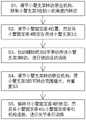
如图8所示,一种利所述的一种关节辅助训装置的关节辅助训练方法,该方法包含以下步骤:As shown in FIG. 8 , a joint auxiliary training method of a joint auxiliary training device described in the description comprises the following steps:
S1,调节所述小臂支架转动限位机构,限制所述小臂支架3可在较小的角度内范围转动。S1, adjust the rotation limit mechanism of the forearm bracket to limit the rotation of the
S2,根据使用者手臂长度调节所述小臂固定座4位置,然后通过所述小臂固定座锁定机构将所述小臂固定座4锁定在所述小臂支架3上,并将损伤手臂的大臂置于所述大臂固定座2内、小臂置于所述小臂固定座4内。S2, adjust the position of the
S3,通过未损伤手臂拉动所述辅助把302手带动所述小臂支架3转动,进行被动活动训练。S3, the
S4,调节所述小臂支架转动限位机构,使所述小臂支架3的可转动范围增大,并重复S3。S4, adjust the rotation limit mechanism of the forearm support to increase the rotatable range of the
S5,通过调节所述小臂固定座锁定机构解除对所述小臂固定座4的锁定,然后将所述小臂固定座4与所述小臂固定座牵引机构连接,进行关节牵引训练。S5 , the
以上显示和描述了本发明的基本原理、主要特征及本发明的优点。本行业的技术人员应该了解,本发明不受上述实施例的限制,上述实施例和说明书中描述的只是说明本发明的原理,在不脱离本发明精神和范围的前提下,本发明还会有各种变化和改进,这些变化和改进都落入要求保护的本发明范围内。本发明要求保护范围由所附的权利要求书及其等效物界定。The foregoing has shown and described the basic principles, main features, and advantages of the present invention. Those skilled in the art should understand that the present invention is not limited by the above-mentioned embodiments, and the descriptions in the above-mentioned embodiments and the description are only to illustrate the principle of the present invention. Without departing from the spirit and scope of the present invention, the present invention will have Various changes and modifications fall within the scope of the claimed invention. The claimed scope of the present invention is defined by the appended claims and their equivalents.
Claims (9)
Priority Applications (1)
| Application Number | Priority Date | Filing Date | Title |
|---|---|---|---|
| CN201911077349.4ACN110840697A (en) | 2019-11-06 | 2019-11-06 | A kind of joint auxiliary training device and method |
Applications Claiming Priority (1)
| Application Number | Priority Date | Filing Date | Title |
|---|---|---|---|
| CN201911077349.4ACN110840697A (en) | 2019-11-06 | 2019-11-06 | A kind of joint auxiliary training device and method |
Publications (1)
| Publication Number | Publication Date |
|---|---|
| CN110840697Atrue CN110840697A (en) | 2020-02-28 |
Family
ID=69598328
Family Applications (1)
| Application Number | Title | Priority Date | Filing Date |
|---|---|---|---|
| CN201911077349.4APendingCN110840697A (en) | 2019-11-06 | 2019-11-06 | A kind of joint auxiliary training device and method |
Country Status (1)
| Country | Link |
|---|---|
| CN (1) | CN110840697A (en) |
Cited By (3)
| Publication number | Priority date | Publication date | Assignee | Title |
|---|---|---|---|---|
| CN111513992A (en)* | 2020-06-02 | 2020-08-11 | 辽宁科技大学 | Physical therapy device is tempered to recovered arm |
| CN113080943A (en)* | 2021-03-30 | 2021-07-09 | 中国人民解放军陆军特色医学中心 | Shoulder joint mobility measuring device |
| CN115998574A (en)* | 2022-07-29 | 2023-04-25 | 杭州程天科技发展有限公司 | Rehabilitation exercise device for upper limbs and lower limbs |
Citations (8)
| Publication number | Priority date | Publication date | Assignee | Title |
|---|---|---|---|---|
| CN201328990Y (en)* | 2008-12-10 | 2009-10-21 | 南京康龙威康复医学工程有限公司 | Intelligent multifunctional upper limb healing device |
| CN201469592U (en)* | 2009-07-29 | 2010-05-19 | 常州市钱璟康复器材有限公司 | Elbow joint traction training chair |
| US20160270996A1 (en)* | 2013-05-31 | 2016-09-22 | Sichuan Xukang Medical Electrical Equipment Co., Ltd. | Joint Rehabilitation Training System Based on the Remote Control, its Implementation Method and Evaluation Method of Joint Range of Motion |
| KR20160139595A (en)* | 2015-05-28 | 2016-12-07 | 동의대학교 산학협력단 | Elbow rehabilition apparatus with orthotic brace function |
| CN207492925U (en)* | 2017-04-17 | 2018-06-15 | 石家庄德度光电科技有限公司 | The front and rear rotation dysfunction training aids of elbow joint |
| CN207804446U (en)* | 2017-06-27 | 2018-09-04 | 石家庄德度光电科技有限公司 | A kind of elbow joint traction therapeutic device |
| CN109700632A (en)* | 2019-02-18 | 2019-05-03 | 石家庄德度光电科技有限公司 | Elbow joint exerciser |
| CN109998865A (en)* | 2019-05-06 | 2019-07-12 | 宿州学院 | A kind of limbs restoring training apparatus tool arm |
- 2019
- 2019-11-06CNCN201911077349.4Apatent/CN110840697A/enactivePending
Patent Citations (8)
| Publication number | Priority date | Publication date | Assignee | Title |
|---|---|---|---|---|
| CN201328990Y (en)* | 2008-12-10 | 2009-10-21 | 南京康龙威康复医学工程有限公司 | Intelligent multifunctional upper limb healing device |
| CN201469592U (en)* | 2009-07-29 | 2010-05-19 | 常州市钱璟康复器材有限公司 | Elbow joint traction training chair |
| US20160270996A1 (en)* | 2013-05-31 | 2016-09-22 | Sichuan Xukang Medical Electrical Equipment Co., Ltd. | Joint Rehabilitation Training System Based on the Remote Control, its Implementation Method and Evaluation Method of Joint Range of Motion |
| KR20160139595A (en)* | 2015-05-28 | 2016-12-07 | 동의대학교 산학협력단 | Elbow rehabilition apparatus with orthotic brace function |
| CN207492925U (en)* | 2017-04-17 | 2018-06-15 | 石家庄德度光电科技有限公司 | The front and rear rotation dysfunction training aids of elbow joint |
| CN207804446U (en)* | 2017-06-27 | 2018-09-04 | 石家庄德度光电科技有限公司 | A kind of elbow joint traction therapeutic device |
| CN109700632A (en)* | 2019-02-18 | 2019-05-03 | 石家庄德度光电科技有限公司 | Elbow joint exerciser |
| CN109998865A (en)* | 2019-05-06 | 2019-07-12 | 宿州学院 | A kind of limbs restoring training apparatus tool arm |
Cited By (4)
| Publication number | Priority date | Publication date | Assignee | Title |
|---|---|---|---|---|
| CN111513992A (en)* | 2020-06-02 | 2020-08-11 | 辽宁科技大学 | Physical therapy device is tempered to recovered arm |
| CN113080943A (en)* | 2021-03-30 | 2021-07-09 | 中国人民解放军陆军特色医学中心 | Shoulder joint mobility measuring device |
| CN113080943B (en)* | 2021-03-30 | 2022-09-13 | 中国人民解放军陆军特色医学中心 | Shoulder joint mobility measuring device |
| CN115998574A (en)* | 2022-07-29 | 2023-04-25 | 杭州程天科技发展有限公司 | Rehabilitation exercise device for upper limbs and lower limbs |
Similar Documents
| Publication | Publication Date | Title |
|---|---|---|
| CN110840697A (en) | A kind of joint auxiliary training device and method | |
| CN110404229B (en) | Leg rehabilitation training device for sickbed | |
| GB2611670A (en) | Passive lower limb power-assisted exoskeleton based on gravitational potential energy locking | |
| CN109966117B (en) | Passive wearable walking-aid robot | |
| CN111037540A (en) | An accompanying chair with ratchet knee joint | |
| CN107951677A (en) | A kind of knee-joint rehabilitation training device | |
| CN209734473U (en) | Therapeutic device for joint loosening | |
| CN113616473A (en) | Upper limb rehabilitation device | |
| CN205866821U (en) | Portable tractor is used to orthopedics | |
| CN106420023B (en) | A kind of orthopaedics portable multifunctional tractor | |
| CN112656569A (en) | External fixation locking device for distal radius fracture treatment | |
| CN111643320A (en) | Hip and knee linkage mechanism of lower limb exoskeleton robot and robot | |
| CN205924406U (en) | A rehabilitation chair for department of neurology | |
| CN211798589U (en) | Splint device for orthopedics fixation convenient to use | |
| CN113893129A (en) | A device for restraining spasticity in standing position of hemiplegic patients | |
| CN218923121U (en) | Orthopedics rehabilitation traction frame | |
| CN209864519U (en) | Postoperative rehabilitation device for leg fracture | |
| CN113367931A (en) | Lower limb rehabilitation assisting device | |
| CN111134936A (en) | Body position restraint device for nursing | |
| CN221557465U (en) | Recovered arm exercise device of using of orthopedics | |
| CN220860598U (en) | Cardiopulmonary rehabilitation training area with adjustable | |
| CN218248349U (en) | Leg physical therapy device for orthopedic postoperative rehabilitation | |
| CN219595134U (en) | Shoulder joint rehabilitation training device | |
| CN215228966U (en) | Knee joint correction fixer | |
| CN215080377U (en) | Auxiliary device for improving walking gait of hemiplegic patient |
Legal Events
| Date | Code | Title | Description |
|---|---|---|---|
| PB01 | Publication | ||
| PB01 | Publication | ||
| SE01 | Entry into force of request for substantive examination | ||
| SE01 | Entry into force of request for substantive examination | ||
| RJ01 | Rejection of invention patent application after publication | ||
| RJ01 | Rejection of invention patent application after publication | Application publication date:20200228 |