CN110840326A - Vacuum cleaners and vacuum cleaners - Google Patents
Vacuum cleaners and vacuum cleanersDownload PDFInfo
- Publication number
- CN110840326A CN110840326ACN201911323627.XACN201911323627ACN110840326ACN 110840326 ACN110840326 ACN 110840326ACN 201911323627 ACN201911323627 ACN 201911323627ACN 110840326 ACN110840326 ACN 110840326A
- Authority
- CN
- China
- Prior art keywords
- air
- dust
- dust separating
- airflow generator
- airflow
- Prior art date
- Legal status (The legal status is an assumption and is not a legal conclusion. Google has not performed a legal analysis and makes no representation as to the accuracy of the status listed.)
- Granted
Links
Images


Classifications
- A—HUMAN NECESSITIES
- A47—FURNITURE; DOMESTIC ARTICLES OR APPLIANCES; COFFEE MILLS; SPICE MILLS; SUCTION CLEANERS IN GENERAL
- A47L—DOMESTIC WASHING OR CLEANING; SUCTION CLEANERS IN GENERAL
- A47L5/00—Structural features of suction cleaners
- A47L5/12—Structural features of suction cleaners with power-driven air-pumps or air-compressors, e.g. driven by motor vehicle engine vacuum
- A47L5/22—Structural features of suction cleaners with power-driven air-pumps or air-compressors, e.g. driven by motor vehicle engine vacuum with rotary fans
- A47L5/24—Hand-supported suction cleaners
- A—HUMAN NECESSITIES
- A47—FURNITURE; DOMESTIC ARTICLES OR APPLIANCES; COFFEE MILLS; SPICE MILLS; SUCTION CLEANERS IN GENERAL
- A47L—DOMESTIC WASHING OR CLEANING; SUCTION CLEANERS IN GENERAL
- A47L9/00—Details or accessories of suction cleaners, e.g. mechanical means for controlling the suction or for effecting pulsating action; Storing devices specially adapted to suction cleaners or parts thereof; Carrying-vehicles specially adapted for suction cleaners
- A47L9/0081—Means for exhaust-air diffusion; Means for sound or vibration damping
- A—HUMAN NECESSITIES
- A47—FURNITURE; DOMESTIC ARTICLES OR APPLIANCES; COFFEE MILLS; SPICE MILLS; SUCTION CLEANERS IN GENERAL
- A47L—DOMESTIC WASHING OR CLEANING; SUCTION CLEANERS IN GENERAL
- A47L9/00—Details or accessories of suction cleaners, e.g. mechanical means for controlling the suction or for effecting pulsating action; Storing devices specially adapted to suction cleaners or parts thereof; Carrying-vehicles specially adapted for suction cleaners
- A47L9/10—Filters; Dust separators; Dust removal; Automatic exchange of filters
- A47L9/102—Dust separators
- A—HUMAN NECESSITIES
- A47—FURNITURE; DOMESTIC ARTICLES OR APPLIANCES; COFFEE MILLS; SPICE MILLS; SUCTION CLEANERS IN GENERAL
- A47L—DOMESTIC WASHING OR CLEANING; SUCTION CLEANERS IN GENERAL
- A47L9/00—Details or accessories of suction cleaners, e.g. mechanical means for controlling the suction or for effecting pulsating action; Storing devices specially adapted to suction cleaners or parts thereof; Carrying-vehicles specially adapted for suction cleaners
- A47L9/10—Filters; Dust separators; Dust removal; Automatic exchange of filters
- A47L9/16—Arrangement or disposition of cyclones or other devices with centrifugal action
- A47L9/1683—Dust collecting chambers; Dust collecting receptacles
Landscapes
- Engineering & Computer Science (AREA)
- Mechanical Engineering (AREA)
- Separating Particles In Gases By Inertia (AREA)
- Filters For Electric Vacuum Cleaners (AREA)
Abstract
Description
Translated fromChinese技术领域technical field
本发明涉及吸尘技术领域,特别是涉及吸尘装置及吸尘设备。The present invention relates to the technical field of vacuuming, and in particular, to a vacuuming device and a vacuuming device.
背景技术Background technique
随着人们生活水平的提高,对周围的清洁环境也要求越来越高,尤其家庭清洁中,需要对住宅内部的脏污进行彻底的清洁,但是通过传统的方式不能够满足室内的干净度,而且费时费力,而吸尘器能够有效和快速的清洁室内的污渍和脏污,满足人们要求。因此,被人们广泛的应用。With the improvement of people's living standards, the requirements for the surrounding clean environment are getting higher and higher, especially in household cleaning, it is necessary to thoroughly clean the dirt inside the house, but the traditional method cannot meet the indoor cleanliness. Moreover, it is time-consuming and labor-intensive, while the vacuum cleaner can effectively and quickly clean the stains and dirt in the room to meet people's requirements. Therefore, it is widely used by people.
吸尘器包括电机和分离器,电机用于带动外部气流进入分离器,分离器对气流中的灰尘进行分离后,排出干净的空气。其中,电机工作时提供空气动力,会产生较大的噪音,影响用户使用吸尘器。The vacuum cleaner includes a motor and a separator, the motor is used to drive the external air flow into the separator, and the separator separates the dust in the air flow and discharges clean air. Among them, the motor provides aerodynamic power when working, which will generate relatively large noise, which affects the user's use of the vacuum cleaner.
发明内容SUMMARY OF THE INVENTION
基于此,有必要提供一种工作时噪音较小的吸尘装置及吸尘设备。Based on this, it is necessary to provide a vacuum cleaner and a vacuum cleaner with less noise during operation.
一种吸尘装置,包括:A vacuum cleaner, comprising:
外壳;shell;
气流发生器,设于所述外壳内,提供带动外界气流流入所述吸尘装置的气流吸力;an airflow generator, which is arranged in the casing and provides airflow suction that drives the external airflow into the dust suction device;
第一气尘分离件,设于所述外壳内,且具有位于所述气流发生器上游的第一气尘分离腔;a first air-dust separation part, which is arranged in the casing and has a first air-dust separation chamber upstream of the airflow generator;
其中,所述第一气尘分离件围绕所述气流发生器的外周设置,且所述第一气尘分离件与所述气流发生器之间形成有位于所述气流发生器下游并与所述气流发生器连通的排气通道。Wherein, the first air-dust separation member is arranged around the outer periphery of the airflow generator, and a space is formed between the first air-dust separation member and the airflow generator, which is located downstream of the airflow generator and is connected to the airflow generator. The air flow generator communicates with the exhaust passage.
上述吸尘装置中,第一气尘分离件围绕气流发生器的外周设置,而第一气尘分离件内部形成有第一气尘分离腔。如此,在气流发生器外周设置第一气尘分离腔,可以通过第一气尘分离腔吸收气流发生器工作时产生的噪音,降低吸尘装置的噪音。并且,第一气尘分离件与气流发生器之间形成有位于气流发生器下游并与气流发生器连通的排气通道,从第一气尘分离腔流出的干净空气经过气流发生器后进入排气通道,从排气通道排向外界。同时,气流发生器与第一气尘分离件之间围设形成排气通道,相当于排气通道位于气流发生器外周,可进一步吸收气流发生器工作时产生的噪音,进一步降低吸尘装置的噪音,提高静音性,方便用户使用吸尘器。In the above-mentioned dust collecting device, the first air-dust separation member is arranged around the outer periphery of the airflow generator, and a first air-dust separation cavity is formed inside the first air-dust separation member. In this way, the first air-dust separation cavity is arranged on the outer periphery of the air flow generator, and the noise generated when the air flow generator is working can be absorbed by the first air-dust separation cavity, thereby reducing the noise of the dust collecting device. In addition, an exhaust channel located downstream of the airflow generator and communicated with the airflow generator is formed between the first air-dust separation member and the airflow generator, and the clean air flowing out from the first air-dust separation chamber passes through the airflow generator and enters the exhaust air. The air passage is discharged from the exhaust passage to the outside. At the same time, an exhaust channel is formed between the airflow generator and the first air-dust separation member, which is equivalent to the exhaust channel located on the outer periphery of the airflow generator, which can further absorb the noise generated by the airflow generator when it is working, and further reduce the dust collector. Noise, improve quietness, convenient for users to use the vacuum cleaner.
在其中一个实施例中,还包括具有第二气尘分离腔的第二气尘分离件,所述第二气尘分离件上开设有与所述第二气尘分离腔连通的进气口,且所述第二气尘分离腔位于所述第一气尘分离腔上游并与所述第一气尘分离腔连通。In one of the embodiments, it further includes a second air-dust separation member having a second air-dust separation chamber, and an air inlet communicated with the second air-dust separation chamber is opened on the second air-dust separation member, And the second air-dust separation chamber is located upstream of the first air-dust separation chamber and communicates with the first air-dust separation chamber.
在其中一个实施例中,所述外壳与所述第一气尘分离件之间形成有进气通道,所述进气通道连通于所述第一气尘分离腔和所述第二气尘分离腔之间。In one embodiment, an air intake channel is formed between the housing and the first air and dust separation member, and the air intake channel is communicated with the first air and dust separation chamber and the second air and dust separation chamber between the cavities.
在其中一个实施例中,还包括与所述第一气尘分离件连接的集尘件,所述集尘件位于所述第一气尘分离件的重力方向上,且具有与所述第一气尘分离腔连通的第一集尘腔。In one of the embodiments, it further includes a dust collecting member connected to the first air-dust separation member, the dust collecting member is located in the direction of gravity of the first air-dust separation member, and has a connection with the first air-dust separation member. The first dust collecting chamber communicated with the gas-dust separation chamber.
在其中一个实施例中,所述集尘件套设于所述第二气尘分离件内;In one embodiment, the dust collecting member is sleeved in the second air and dust separation member;
所述集尘件远离所述第一气尘分离件的底端呈开口状,且所述集尘件呈开口状的所述底端与所述第二集尘分离件的底壁抵接。The bottom end of the dust collecting member away from the first air-dust separation member is in an open shape, and the bottom end of the dust collecting member in the open shape is in contact with the bottom wall of the second dust collection and separation member.
在其中一个实施例中,还包括过滤网,所述过滤网间隔套设于所述外壳与所述集尘件之间,且位于由所述第二气尘分离腔至所述第一气尘分离腔的气流路径上。In one of the embodiments, it further includes a filter screen, the filter screen is sleeved between the casing and the dust collecting member at intervals, and is located from the second gas-dust separation chamber to the first gas-dust separation chamber on the airflow path of the separation chamber.
在其中一个实施例中,还包括具有导流腔的导流件,所述导流件对应所述气流发生器的出气侧与所述第一气尘分离件对接,所述导流腔连通于所述气流发生器的出气口与所述排气通道的入口之间。In one of the embodiments, it further includes a flow guide member having a flow guide cavity, the flow guide member is connected to the first air-dust separation member corresponding to the air outlet side of the airflow generator, and the flow guide cavity is connected to the between the air outlet of the airflow generator and the inlet of the exhaust passage.
在其中一个实施例中,所述导流件包括本体和连接板,所述本体具有所述导流腔,所述连接板设置于所述本体,且所述第一气尘分离件与所述连接板对接。In one embodiment, the flow guide includes a main body and a connecting plate, the main body has the flow guide cavity, the connecting plate is arranged on the main body, and the first air and dust separation member is connected to the Connection board docking.
在其中一个实施例中,还包括引流件,所述引流件设于所述外壳内;In one of the embodiments, it further includes a drainage member, the drainage member is provided in the housing;
其中,所述第一气尘分离件的排气口与所述气流发生器的吸气口位于所述外壳内的同一端,所述引流件设于所述气流发生器的吸气侧且具有连通所述第一气尘分离件的排气口与所述气流发生器的吸气口的引流通道。Wherein, the exhaust port of the first air-dust separation member and the suction port of the airflow generator are located at the same end in the casing, and the drainage member is arranged on the suction side of the airflow generator and has A drainage channel that communicates with the exhaust port of the first air-dust separation member and the suction port of the airflow generator.
在其中一个实施例中,所述引流件与所述外壳之间围设形成有与所述排气通道的出口连通的引流腔,所述外壳上开设有与所述引流腔连通的排气孔。In one embodiment, a drainage cavity that communicates with the outlet of the exhaust passage is formed between the drainage member and the casing, and an exhaust hole communicated with the drainage cavity is formed on the outer shell. .
在其中一个实施例中,所述外壳包括顶壁及围绕所述顶壁的外周设置的侧壁,所述引流件相对所述顶壁设置于所述外壳内,且与所述顶壁及所述侧壁之间围合形成所述引流腔,所述侧壁围合形成所述引流腔的部分上开设有所述排气孔。In one embodiment, the casing includes a top wall and a side wall disposed around the outer circumference of the top wall, the flow guiding member is disposed in the casing opposite to the top wall, and is connected with the top wall and all the side walls. The drainage cavity is formed by enclosing the side walls, and the exhaust hole is formed on the part of the side wall that encloses the drainage cavity.
一种吸尘设备,包括上述吸尘装置。A dust collector, comprising the above-mentioned dust collector.
附图说明Description of drawings
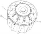
图1为本发明一实施例中吸尘装置的结构示意图;1 is a schematic structural diagram of a dust collector in an embodiment of the present invention;
图2为图1所示吸尘装置一个方向的截面示意图;FIG. 2 is a schematic cross-sectional view of the dust collector shown in FIG. 1 in one direction;
图3为图1所示吸尘装置另一方向的截面示意图;FIG. 3 is a schematic cross-sectional view of the vacuum cleaner shown in FIG. 1 in another direction;
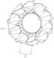
图4图1所示吸尘装置中第一气尘分离件一个视角的结构示意图;Fig. 4 is a schematic structural diagram of the first air-dust separating member in the vacuum cleaner shown in Fig. 1 from a viewing angle;
图5为图4所示第一气尘分离件另一视角的结构示意图;FIG. 5 is a schematic structural diagram of the first air-dust separating member shown in FIG. 4 from another perspective;
图6为图1所示吸尘装置中第一气尘分离件与引流件一个视角的装配示意图;FIG. 6 is a schematic view of the assembly of the first air-dust separating member and the drainage member from a perspective of the dust collector shown in FIG. 1;
图7为图6所示第一气尘分离件与引流件另一视角的装配示意图。FIG. 7 is a schematic view of the assembly of the first air-dust separating member and the flow-guiding member shown in FIG. 6 from another perspective.
具体实施方式Detailed ways
为了便于理解本发明,下面将参照相关附图对本发明进行更全面的描述。附图中给出了本发明的较佳实施例。但是,本发明可以以许多不同的形式来实现,并不限于本文所描述的实施例。相反地,提供这些实施例的目的是使对本发明的公开内容的理解更加透彻全面。In order to facilitate understanding of the present invention, the present invention will be described more fully hereinafter with reference to the related drawings. Preferred embodiments of the invention are shown in the accompanying drawings. However, the present invention may be embodied in many different forms and is not limited to the embodiments described herein. Rather, these embodiments are provided so that a thorough and complete understanding of the present disclosure is provided.
需要说明的是,当元件被称为“固定于”另一个元件,它可以直接在另一个元件上或者也可以存在居中的元件。当一个元件被认为是“连接”另一个元件,它可以是直接连接到另一个元件或者可能同时存在居中元件。It should be noted that when an element is referred to as being "fixed to" another element, it can be directly on the other element or intervening elements may also be present. When an element is referred to as being "connected" to another element, it can be directly connected to the other element or intervening elements may also be present.
除非另有定义,本文所使用的所有的技术和科学术语与属于本发明的技术领域的技术人员通常理解的含义相同。本文中在本发明的说明书中所使用的术语只是为了描述具体的实施例的目的,不是旨在于限制本发明。本文所使用的术语“和/或”包括一个或多个相关的所列项目的任意的和所有的组合。Unless otherwise defined, all technical and scientific terms used herein have the same meaning as commonly understood by one of ordinary skill in the art to which this invention belongs. The terms used herein in the description of the present invention are for the purpose of describing specific embodiments only, and are not intended to limit the present invention. As used herein, the term "and/or" includes any and all combinations of one or more of the associated listed items.
如图1-3所示,本发明一实施例中,提供一种吸尘装置100,包括外壳10、电源16及均设于外壳10内的气流发生器30和第一气尘分离件50。As shown in FIGS. 1-3 , in an embodiment of the present invention, a
电源16用于向气流发生器30供电,气流发生器30提供带动外界气流流入吸尘器的气流吸力,第一气尘分离件50具有位于气流发生器30上游的第一气尘分离腔52。气流发生器30工作时产生的气流吸力,带动外界气流进入第一气尘分离腔52进行气尘分离,完成灰尘分离的干净空气从第一气尘分离腔52流出后经过气流发生器30排向外界,如此完成吸尘工作。The power source 16 is used to supply power to the
如图2及图7所示,一些实施例中,第一气尘分离件50围绕气流发生器30的外周设置,且第一气尘分离件50内部形成有第一气尘分离腔52。这样,第一气尘分离腔52围绕于气流发生器30外周,可以通过第一气尘分离腔52吸收气流发生器30工作时产生的噪音,降低吸尘装置100的噪音。并且,第一气尘分离件50与气流发生器30之间形成有位于气流发生器30下游并与气流发生器30连通的排气通道60,从第一气尘分离腔52流出的干净空气经过气流发生器30后进入排气通道60,从排气通道60排向外界。同时,气流发生器30与第一气尘分离件50之间围设形成排气通道60,相当于排气通道60位于气流发生器30外周,可进一步吸收气流发生器30工作时产生的噪音,进一步降低吸尘装置100的噪音,提高静音性,方便用户使用吸尘器。As shown in FIGS. 2 and 7 , in some embodiments, the first air-
如图4-5所示,具体地,第一气尘分离件50包括多个第一子气尘分离件51,第一气尘分离腔52包括多个形成于每个第一子气尘分离件51内的第一子气尘分离腔521。多个第一子气尘分离件51围绕气流发生器30的外周呈环形排布连接,每个第一子气尘分离件51内的第一子气尘分离腔521对流入的气流进行气尘分离,通过多个第一子气尘分离腔521高效地进行气尘分离。同时,通过多个围绕于气流发生器30外周的第一子气尘分离腔521吸收气流发生器30产生的噪音。As shown in FIGS. 4-5 , specifically, the first gas-
可选地,每个第一子气尘分离件51为旋风分离器,当带有灰尘和赃物的气流进入旋风分离器后螺旋向下转动,而灰尘和赃物在转动过程中因为质量较大可以获得较大的离心力,最后撞击到旋风分离器的内壁后在自身重力作用下掉入集尘腔,同时干净的空气由旋风分离器排出,如此实现气尘分离。Optionally, each first sub-air-
如图2-3所示,一些实施例中,吸尘装置100还包括具有第二气尘分离腔41的第二气尘分离件40,第二气尘分离件40上开设有与第二气尘分离腔41连通的进气口43,且第二气尘分离腔41位于第一气尘分离腔52上游并与第一气尘分离腔52连通。也就是说,在第一气尘分离件50之前还设置有第二气尘分离件40,气流发生器30产生的气流吸力,带动气流先由进气口43进入第二气尘分离件40进行一次气尘分离,然后再进入第一气尘分离件50再进行次气尘分离,如此实现对空气二次气尘分离,气尘分离率更高,分离效果更好。As shown in FIGS. 2-3 , in some embodiments, the
进一步地,外壳10与第一气尘分离件50之间形成有进气通道12,进气通道12连通于第一气尘分离腔52和第二气尘分离腔41之间,第二气尘分离腔41内的气流通过进气通道12进入第一气尘分离腔52。并且,第一气尘分离件50围绕气流发生器30的外周设置,而位于第一气尘分离件50与外壳10之间的进气通道12,也会围绕于第一气尘分离件50外,进而位于气流发生器30外周,如此还可通过进气通道12吸收气流发生器30产生的噪音。Further, an
具体地,气流发生器30外依次围设有位于气流发生器30与第一气尘分离件50之间的排气通道60、位于第一气尘分离件50内的第一气尘分离腔52、及位于第一气尘分离件50与外壳10之间的进气通道12,即排气通道60、第一气尘分离腔52及进气通道12由内向外依次排布在气流发生器30外周,对气流发生器30产生的噪音进行多层吸收,有效降低吸尘装置100工作时传递出的噪音,提高用户的使用体验。Specifically, the
一些实施例中,吸尘装置100还包括引流件70,引流件70设于外壳10内。并且,第一气尘分离件50的排气口与气流发生器30的吸气口位于外壳10内的同一端,引流件70设于气流发生器30的吸气侧且具有连通第一气尘分离件50的排气口与气流发生器30的吸气口的引流通道72,第一气尘分离件50中排出的干净空气通过引流通道72流向气流发生器30。同时,第一气尘分离件50的排气口位于气流发生器30的吸气侧,引流通道72只需在气流发生器30的吸气端设置,便可连通第一气尘分离件的排气口与气流发生器30的吸气口,引流通道72较短,气流的流动阻力较小,加速气流流速,提高吸气流量。In some embodiments, the
具体地,气流发生器30包括电机和连接于电机输出端的风叶,电机工作时带动风叶旋转,进而形成带动气流进入吸尘装置100的气流吸力。其中,气流发生器30具有风叶的一端为吸气端,将气流发生器30具有风叶的一端设置为与第一气尘分离件50的排气端位于同一侧,如此便可将气流发生器30的吸气端与第一气尘分离件50的排气端设置于同一侧,减小气流在第一气尘分离件50与气流发生器30之间流动的阻力。Specifically, the
更具体地,吸尘装置100还包括前置过滤器32,前置过滤器32套设于气流发生器30的吸器端,即前置过滤器32套设于气流发生器30具有风叶的一端,且前置过滤器32与引流通道72连通,以过滤由引流通道72流向气流发生器30内的气流,防止气流发生器30内部积聚灰尘。而且,壳体10上开设有与气流发生器30的吸气端对应的安装口15,前置过滤器32可拆卸地装配于安装口15内,在需要清洗前置过滤器32时,可从壳体10的安装口15处方便地拆卸前置过滤器32。More specifically, the
进一步地,引流件70与外壳10之间围设形成有与排气通道60的出口连通的引流腔74,外壳10上开设有与引流腔74连通的排气孔14。将引流件70设于气流发生器30的吸气侧后,引流件70外壁与外壳10内壁之间还围设形成与排气通道60的出口连通的引流腔74,通过引流腔74将排气通道60中的干净空气通过排气孔14排向外部。如此,引流件70不仅自身内部形成引流通道72,引流件70还与外壳10之间界定形成引流腔74,实现多重功能。Further, a
如图4-6所示,具体地,第一气尘分离件50上开设有第一过孔53,第一过孔53连通排气通道60的出口,引流件70上对应第一过孔53开设有第二过孔73,第二过孔73连通引流腔74,气流由排气通道60经过第一过孔53和第二过孔73后进入引流腔74,最后由排气孔14排出。As shown in FIGS. 4-6 , specifically, the first air-
如图3所示,更进一步地,外壳10包括顶壁11及围绕顶壁11外周设置的侧壁13,引流件70相对顶壁11设置于外壳10内且与顶壁11及侧壁13之间围合形成引流腔74,侧壁13围合形成引流腔74的部分上开设有排气孔14,使排气孔14与引流腔74连通,且排气孔14位于侧壁13靠近顶壁11的上半部分。如此,由外壳10侧面的上半部分出气,排出的气流不会吹到已经被吸尘过的清洁面,不会将未清洁处的灰尘吹到清洁面,防止影响清洁效果。并且,也不会直接由壳体10的顶部直接排气而吹到操作者面部,保护操作者,方便用户使用,提高用户体验度。As shown in FIG. 3 , further, the
如图2-3所示,一些实施例中,吸尘装置100还包括具有导流腔92的导流件90,导流件90对应气流发生器30的出气侧与第一气尘分离件50对接,导流腔92连通于气流发生器30的出气口与排气通道60的入口之间。由前述描述可知,排气通道60围设于气流发生器30外周,所以排气通道60的延伸方向与气流发生器30内的气流流向平行,为了让从气流发生器30内竖向流动的气流进入相邻竖向的排气通道60内,在气流发生器30的出气口侧设置导流件90,通过导流件90引导由气流发生器30排出的气流进入排气通道60。As shown in FIGS. 2-3 , in some embodiments, the
具体地,导流件90包括本体91和连接板93,本体91具有导流腔92,连接板93设置于本体91,且第一气尘分离件50与连接板93对接。在装配吸尘装置100时,可将第一气尘分离件50配接到连接板93上,且使与连接板93连接的本体91朝向被第一气尘分离件50围绕的气流发生器30的出气端,引导气流由气流发生器30的出气端进入相邻的排气通道60。Specifically, the
一些实施例中,吸尘装置100还包括与第一气尘分离件50连接的集尘件80,集尘件80位于第一气尘分离件50的重力方向上,且具有与第一气尘分离腔52连通的第一集尘腔81,当带有灰尘的气流在第一气尘分离腔52内高速旋转时,灰尘因为较大的离心力撞击到第一气尘分离腔52的内壁上并在自身重力作用下掉入第一集尘腔81,通过第一集尘腔81收集第一气尘分离腔52中分离出的灰尘。In some embodiments, the
进一步地,集尘件80套设于第二气尘分离件40内,且集尘件80远离第一气尘分离件50的底端呈开口状,且集尘件80呈开口状的底端与第二气尘分离件40的底壁抵接。这样,集尘件80伸入第二气尘分离腔41内,通过第二气尘分离腔41容置集尘件80。并且,集尘件80的底端呈开口状与第二气尘分离腔41的底壁抵接,第一集尘腔81内的灰尘通过第二气尘分离件40的底壁支撑。同时,第二气尘分离腔41内高速旋转后分离出的灰尘,在自身重力作用下掉落在第二气尘分离件40的底壁上。第一气尘分离件50和第二气尘分离件40分离出的灰尘,最终都聚集在第二气尘分离件40的底壁上。倒尘时只需打开第二气尘分离件40的底壁,便可将集尘件80及第二气尘分离腔41内的灰尘都倒出;或者,倒尘时拆卸第二气尘分离件40,将均聚集在第二气尘分离件40底壁上的灰尘由第二气尘分离件40允许集尘件80通过的开口倒出,便可一次性清理第一气尘分离件50和第二气尘分离件40分离出的灰尘。Further, the
可选地,集尘件80包括集尘段82和连接于集尘段82与第一气尘分离件50之间的过渡段84,过渡段84在自身由外向内的径向上向靠近集尘段82倾斜,如此过渡段84向靠近集尘段82中心向下倾斜,引导灰尘聚集到集尘段82内。同时,通过倾斜的过渡段84可将第二气尘分离腔41内分离后的干净空气平缓地引入进气通道12内。另外,在第一气尘分离件50指向集尘段82的方向上过渡段84的直径逐渐减小,与过渡段84连接的集尘段82以过渡段84的最小直径设置,具有较小的直径,占用第二气尘分离腔41的空间较小,不会影响第二气尘分离腔41内的气尘分离工作。Optionally, the
一些实施例中,吸尘装置100还包括过滤网20,过滤网20间隔套设于外壳10与集尘件80之间,且位于由第二气尘分离腔41至第一气尘分离腔52的气流路径上,对由第二气尘分离腔41流向第一气尘分离腔52的气流进行过滤,防止较大颗粒的灰尘进入第一气尘分离腔52,进一步提高气尘分离率。In some embodiments, the
请参阅图2及图3,上述吸尘装置100的气流路径为:带有灰尘的气流由进气口43进入第二气尘分离腔41,在第二气尘分离腔41内进行一次气尘分离,然后通过过滤网20后进入进气通道12,由进气通道12进入第一气尘分离腔52,在第一气尘分离腔52内再次进行气尘分离,分离出灰尘的干净气流由第一气尘分离腔52流向引流通道72,再流向气流发生器30,然后由气流发生器30的出气端进入导流腔92后进入排气通道60,最后再进入与排气通道60连通的引流腔74后,从外壳10的侧壁13上的排气孔14流向外界,完成一次吸尘。吸尘装置100工作时,持续带动气流沿上述路径流动,完成吸尘工作。Please refer to FIG. 2 and FIG. 3 , the air flow path of the above-mentioned
基于同样的发明构思,本发明一实施例中,还提供一种吸尘设备,包括上述吸尘装置100,工作时的噪音较小。Based on the same inventive concept, in an embodiment of the present invention, there is also provided a vacuuming device, including the above-mentioned
一些实施例中,吸尘设备还包括管体件和清洁件,管体件的一端设置有清洁件,管体件的另一端套设于进气口43处。吸尘设备工作时,使清洁件接触待清洁面,并带起待清洁面上的灰尘,使灰尘与空气一同由管体件流向进气口43,以进行吸尘工作。可选地,吸尘设备为手持式吸尘器。In some embodiments, the dust collector further includes a tube body and a cleaning member, one end of the tube body member is provided with the cleaning member, and the other end of the tube body member is sleeved at the
以上所述实施例的各技术特征可以进行任意的组合,为使描述简洁,未对上述实施例中的各个技术特征所有可能的组合都进行描述,然而,只要这些技术特征的组合不存在矛盾,都应当认为是本说明书记载的范围。The technical features of the above-described embodiments can be combined arbitrarily. For the sake of brevity, all possible combinations of the technical features in the above-described embodiments are not described. However, as long as there is no contradiction between the combinations of these technical features, All should be regarded as the scope described in this specification.
以上所述实施例仅表达了本发明的几种实施方式,其描述较为具体和详细,但并不能因此而理解为对发明专利范围的限制。应当指出的是,对于本领域的普通技术人员来说,在不脱离本发明构思的前提下,还可以做出若干变形和改进,这些都属于本发明的保护范围。因此,本发明专利的保护范围应以所附权利要求为准。The above-mentioned embodiments only represent several embodiments of the present invention, and the descriptions thereof are specific and detailed, but should not be construed as a limitation on the scope of the invention patent. It should be pointed out that for those of ordinary skill in the art, without departing from the concept of the present invention, several modifications and improvements can also be made, which all belong to the protection scope of the present invention. Therefore, the protection scope of the patent of the present invention should be subject to the appended claims.
Claims (12)
Priority Applications (1)
| Application Number | Priority Date | Filing Date | Title |
|---|---|---|---|
| CN201911323627.XACN110840326B (en) | 2019-12-20 | 2019-12-20 | Dust collection device and dust collection equipment |
Applications Claiming Priority (1)
| Application Number | Priority Date | Filing Date | Title |
|---|---|---|---|
| CN201911323627.XACN110840326B (en) | 2019-12-20 | 2019-12-20 | Dust collection device and dust collection equipment |
Publications (2)
| Publication Number | Publication Date |
|---|---|
| CN110840326Atrue CN110840326A (en) | 2020-02-28 |
| CN110840326B CN110840326B (en) | 2025-06-27 |
Family
ID=69610028
Family Applications (1)
| Application Number | Title | Priority Date | Filing Date |
|---|---|---|---|
| CN201911323627.XAActiveCN110840326B (en) | 2019-12-20 | 2019-12-20 | Dust collection device and dust collection equipment |
Country Status (1)
| Country | Link |
|---|---|
| CN (1) | CN110840326B (en) |
Cited By (7)
| Publication number | Priority date | Publication date | Assignee | Title |
|---|---|---|---|---|
| CN112773248A (en)* | 2020-12-31 | 2021-05-11 | 珠海格力电器股份有限公司 | Handheld dust collector |
| CN112971586A (en)* | 2021-02-22 | 2021-06-18 | 追创科技(苏州)有限公司 | Hand-held vacuum cleaner |
| CN113143105A (en)* | 2021-05-25 | 2021-07-23 | 北京小狗吸尘器集团股份有限公司 | Filtering component and dust collecting equipment |
| CN113171028A (en)* | 2021-05-25 | 2021-07-27 | 北京小狗吸尘器集团股份有限公司 | A diversion filter assembly and dust collection equipment |
| CN113180539A (en)* | 2021-05-25 | 2021-07-30 | 北京小狗吸尘器集团股份有限公司 | Dust collecting equipment |
| CN113180542A (en)* | 2021-05-25 | 2021-07-30 | 北京小狗吸尘器集团股份有限公司 | Motor water conservancy diversion spare and dust collecting equipment |
| CN113180541A (en)* | 2021-05-25 | 2021-07-30 | 北京小狗吸尘器集团股份有限公司 | Motor element and dust collecting equipment |
Citations (6)
| Publication number | Priority date | Publication date | Assignee | Title |
|---|---|---|---|---|
| US20060150587A1 (en)* | 2005-01-07 | 2006-07-13 | Samsung Electronics Co., Ltd. | Cyclonic cleaner |
| KR100617131B1 (en)* | 2005-03-21 | 2006-08-31 | 엘지전자 주식회사 | Dust collector of vacuum cleaner |
| CN204427939U (en)* | 2015-03-12 | 2015-07-01 | 江苏美的春花电器股份有限公司 | The dirt cup of dust catcher and dust catcher |
| US20170296018A1 (en)* | 2016-01-20 | 2017-10-19 | Jiangsu Midea Cleaning Appliances Co., Ltd. | Hand-held vacuum cleaner |
| CN109124461A (en)* | 2017-06-28 | 2019-01-04 | 苏州宝时得电动工具有限公司 | Hand-held cleaners and dust catcher sub-assembly |
| CN211484334U (en)* | 2019-12-20 | 2020-09-15 | 珠海格力电器股份有限公司 | Dust suction device and dust suction equipment |
- 2019
- 2019-12-20CNCN201911323627.XApatent/CN110840326B/enactiveActive
Patent Citations (6)
| Publication number | Priority date | Publication date | Assignee | Title |
|---|---|---|---|---|
| US20060150587A1 (en)* | 2005-01-07 | 2006-07-13 | Samsung Electronics Co., Ltd. | Cyclonic cleaner |
| KR100617131B1 (en)* | 2005-03-21 | 2006-08-31 | 엘지전자 주식회사 | Dust collector of vacuum cleaner |
| CN204427939U (en)* | 2015-03-12 | 2015-07-01 | 江苏美的春花电器股份有限公司 | The dirt cup of dust catcher and dust catcher |
| US20170296018A1 (en)* | 2016-01-20 | 2017-10-19 | Jiangsu Midea Cleaning Appliances Co., Ltd. | Hand-held vacuum cleaner |
| CN109124461A (en)* | 2017-06-28 | 2019-01-04 | 苏州宝时得电动工具有限公司 | Hand-held cleaners and dust catcher sub-assembly |
| CN211484334U (en)* | 2019-12-20 | 2020-09-15 | 珠海格力电器股份有限公司 | Dust suction device and dust suction equipment |
Cited By (10)
| Publication number | Priority date | Publication date | Assignee | Title |
|---|---|---|---|---|
| CN112773248A (en)* | 2020-12-31 | 2021-05-11 | 珠海格力电器股份有限公司 | Handheld dust collector |
| CN112971586A (en)* | 2021-02-22 | 2021-06-18 | 追创科技(苏州)有限公司 | Hand-held vacuum cleaner |
| CN113143105A (en)* | 2021-05-25 | 2021-07-23 | 北京小狗吸尘器集团股份有限公司 | Filtering component and dust collecting equipment |
| CN113171028A (en)* | 2021-05-25 | 2021-07-27 | 北京小狗吸尘器集团股份有限公司 | A diversion filter assembly and dust collection equipment |
| CN113180539A (en)* | 2021-05-25 | 2021-07-30 | 北京小狗吸尘器集团股份有限公司 | Dust collecting equipment |
| CN113180542A (en)* | 2021-05-25 | 2021-07-30 | 北京小狗吸尘器集团股份有限公司 | Motor water conservancy diversion spare and dust collecting equipment |
| CN113180541A (en)* | 2021-05-25 | 2021-07-30 | 北京小狗吸尘器集团股份有限公司 | Motor element and dust collecting equipment |
| CN113143105B (en)* | 2021-05-25 | 2025-07-08 | 北京小狗吸尘器集团股份有限公司 | Filtering component and dust collection equipment |
| CN113180539B (en)* | 2021-05-25 | 2025-07-08 | 北京小狗吸尘器集团股份有限公司 | Dust collection equipment |
| CN113171028B (en)* | 2021-05-25 | 2025-08-22 | 北京小狗吸尘器集团股份有限公司 | A diversion filter assembly and dust collection equipment |
Also Published As
| Publication number | Publication date |
|---|---|
| CN110840326B (en) | 2025-06-27 |
Similar Documents
| Publication | Publication Date | Title |
|---|---|---|
| CN110840326A (en) | Vacuum cleaners and vacuum cleaners | |
| CN211484334U (en) | Dust suction device and dust suction equipment | |
| CN104545695B (en) | A kind of two grades of dust and gas isolating constructions and comprise the dirt cup of this structure | |
| JP4146351B2 (en) | Filter housing | |
| WO2016197546A1 (en) | Handheld dust collector having spiral two-stage tornado dust-air separation structure | |
| TW201500026A (en) | Dust collecting method and apparatus of self-propelled cleaning equipment | |
| CN102878115A (en) | Debris blowing and/or vacuum appliance | |
| US20240215777A1 (en) | Cleaner | |
| CN101816537A (en) | Cyclonic separating apparatus | |
| CN106308681B (en) | Gas-dust separation device and dust collector | |
| CN204427938U (en) | A kind of secondary dirt gas separation structure and comprise the dirt cup of this structure | |
| CN114794964B (en) | Surface cleaning equipment with dust cup assembly | |
| JP2012120860A (en) | Internal air separator in dirt separation device | |
| CN103190862B (en) | Pneumatic floor brush and vacuum cleaner thereof | |
| CN110772168A (en) | Cleaning equipment and dust collector | |
| CN204698456U (en) | A kind of hand held cleaner with spiral secondary spout travel fatigue gas separation structure | |
| CN110876580A (en) | Vacuum cleaner | |
| CN211324705U (en) | Cleaning equipment and dust collector | |
| CN105266719B (en) | A kind of multi-stage cyclone vacuum cleaner dust cup structure | |
| CN111281264A (en) | Household dust collector | |
| CN215502735U (en) | Cleaning module for cleaning machine and cleaning machine | |
| KR20060015073A (en) | Centrifugal Blower for Vacuum Cleaners | |
| KR100445651B1 (en) | Cyclone type vacuum cleaner | |
| CN210697475U (en) | A handheld vacuum cleaner | |
| US20240122420A1 (en) | Cleaner |
Legal Events
| Date | Code | Title | Description |
|---|---|---|---|
| PB01 | Publication | ||
| PB01 | Publication | ||
| SE01 | Entry into force of request for substantive examination | ||
| SE01 | Entry into force of request for substantive examination | ||
| GR01 | Patent grant | ||
| GR01 | Patent grant |