CN110840269A - Electric cooking appliance - Google Patents
Electric cooking applianceDownload PDFInfo
- Publication number
- CN110840269A CN110840269ACN201810956624.9ACN201810956624ACN110840269ACN 110840269 ACN110840269 ACN 110840269ACN 201810956624 ACN201810956624 ACN 201810956624ACN 110840269 ACN110840269 ACN 110840269A
- Authority
- CN
- China
- Prior art keywords
- cover
- temperature measuring
- cooking appliance
- electric cooking
- protective shell
- Prior art date
- Legal status (The legal status is an assumption and is not a legal conclusion. Google has not performed a legal analysis and makes no representation as to the accuracy of the status listed.)
- Pending
Links
Images

Classifications
- A—HUMAN NECESSITIES
- A47—FURNITURE; DOMESTIC ARTICLES OR APPLIANCES; COFFEE MILLS; SPICE MILLS; SUCTION CLEANERS IN GENERAL
- A47J—KITCHEN EQUIPMENT; COFFEE MILLS; SPICE MILLS; APPARATUS FOR MAKING BEVERAGES
- A47J36/00—Parts, details or accessories of cooking-vessels
- A47J36/06—Lids or covers for cooking-vessels
- A—HUMAN NECESSITIES
- A47—FURNITURE; DOMESTIC ARTICLES OR APPLIANCES; COFFEE MILLS; SPICE MILLS; SUCTION CLEANERS IN GENERAL
- A47J—KITCHEN EQUIPMENT; COFFEE MILLS; SPICE MILLS; APPARATUS FOR MAKING BEVERAGES
- A47J27/00—Cooking-vessels
- A—HUMAN NECESSITIES
- A47—FURNITURE; DOMESTIC ARTICLES OR APPLIANCES; COFFEE MILLS; SPICE MILLS; SUCTION CLEANERS IN GENERAL
- A47J—KITCHEN EQUIPMENT; COFFEE MILLS; SPICE MILLS; APPARATUS FOR MAKING BEVERAGES
- A47J27/00—Cooking-vessels
- A47J27/08—Pressure-cookers; Lids or locking devices specially adapted therefor
- A—HUMAN NECESSITIES
- A47—FURNITURE; DOMESTIC ARTICLES OR APPLIANCES; COFFEE MILLS; SPICE MILLS; SUCTION CLEANERS IN GENERAL
- A47J—KITCHEN EQUIPMENT; COFFEE MILLS; SPICE MILLS; APPARATUS FOR MAKING BEVERAGES
- A47J36/00—Parts, details or accessories of cooking-vessels
Landscapes
- Engineering & Computer Science (AREA)
- Food Science & Technology (AREA)
- Cookers (AREA)
Abstract
Translated fromChinese
Description
Translated fromChinese技术领域technical field
本发明涉及厨房电器的技术领域,具体而言,涉及一种电烹饪器具。The present invention relates to the technical field of kitchen appliances, in particular, to an electric cooking appliance.
背景技术Background technique
目前的电烹饪器具,通常采用采温柱贴合在锅盖的外表面的方法来检测温度。通常情况下,采温柱贴合的位置距离排气孔比较近。长时间工作后,汤汁或者食物会在采温柱附近堆积,这样采温柱与锅盖表面的贴合面会有杂质,干扰热传导,从而影响采温柱检测温度的准确性和速度,从而导致实际温度过高,影响烹饪效果,甚至威胁使用者的安全。Current electric cooking utensils usually use a method in which a temperature collecting column is attached to the outer surface of the pot cover to detect the temperature. Under normal circumstances, the position where the temperature collection column is attached is relatively close to the exhaust hole. After working for a long time, the soup or food will accumulate near the temperature collection column, so that there will be impurities on the surface of the temperature collection column and the surface of the pot cover, which will interfere with heat conduction, thereby affecting the accuracy and speed of the temperature detection column. The actual temperature is too high, which affects the cooking effect and even threatens the safety of users.
发明内容SUMMARY OF THE INVENTION
本发明的主要目的在于提供一种电烹饪器具,以解决现有技术中的汤汁或食物堆积在测温组件附近而影响测温组件的测温效果的问题。The main purpose of the present invention is to provide an electric cooking utensil to solve the problem in the prior art that soup or food accumulates near the temperature measuring component and affects the temperature measuring effect of the temperature measuring component.
为了实现上述目的,本发明提供了一种电烹饪器具,包括:锅体,锅体具有加热装置;锅盖,盖合于锅体上,锅盖包括由下至上依次设置的内锅盖、内衬和面盖,内锅盖上设置有排气口;测温组件,测温组件与内锅盖相贴合以测量内锅盖的温度;测温组件包括保护壳和设置在保护壳内的温度传感器,内锅盖具有朝向面盖的凸台,凸台的上表面高于排气口,保护壳与面盖的凸台相抵接。In order to achieve the above purpose, the present invention provides an electric cooking appliance, comprising: a pot body, the pot body has a heating device; a pot cover, which is covered on the pot body, and the pot cover includes an inner pot cover, an inner pot cover and an inner pot cover arranged sequentially from bottom to top. The lining and the surface cover, the inner pot cover is provided with an exhaust port; the temperature measuring component is fitted with the inner pot cover to measure the temperature of the inner pot cover; the temperature measuring component includes a protective shell and a For the temperature sensor, the inner pot cover has a boss facing the surface cover, the upper surface of the boss is higher than the exhaust port, and the protective shell is in contact with the boss of the surface cover.
进一步地,内衬上设置有通孔,保护壳穿设在通孔内。Further, a through hole is provided on the inner liner, and the protective shell is penetrated in the through hole.
进一步地,内衬上设置有限位部,限位部与保护壳相配合以对保护壳进行限位。Further, a limiting portion is provided on the inner lining, and the limiting portion cooperates with the protective shell to limit the protective shell.
进一步地,限位部设置在靠近面盖的侧面上。Further, the limiting portion is arranged on the side surface close to the face cover.
进一步地,保护壳包括保护壳主体和设置在保护壳主体外壁上的定位环板,内衬的通孔的直径和保护壳主体的外径相适配,定位环板的外径大于内衬的通孔。Further, the protective shell includes a protective shell main body and a positioning ring plate arranged on the outer wall of the protective shell main body, the diameter of the through hole of the inner lining is adapted to the outer diameter of the protective shell main body, and the outer diameter of the positioning ring plate is larger than that of the inner lining. through hole.
进一步地,限位部为筒状结构,限位部的内径与定位环板的外径相适配。Further, the limiting portion is a cylindrical structure, and the inner diameter of the limiting portion is adapted to the outer diameter of the positioning ring plate.
进一步地,锅盖还包括测温盖,测温盖罩设在保护壳上方。Further, the pot cover also includes a temperature measuring cover, and the temperature measuring cover is provided above the protective shell.
进一步地,测温组件还包括测温导线,测温盖上设置有过线孔,测温导线通过过线孔穿出。Further, the temperature measurement assembly further includes a temperature measurement wire, a wire hole is provided on the temperature measurement cover, and the temperature measurement wire passes through the wire hole.
进一步地,锅盖还包括转杆,转杆与测温盖通过紧固件固定在内衬上。Further, the pot cover also includes a rotating rod, and the rotating rod and the temperature measuring cover are fixed on the inner lining through fasteners.
进一步地,电烹饪器具为电压力锅或电饭煲。Further, the electric cooking appliance is an electric pressure cooker or an electric rice cooker.
应用本发明的技术方案,在测温组件与内锅盖贴合的位置设置朝向面盖的凸台,凸台平面高于排气口的平面,汤汁和食物等由于重力原因会向下移动,这样就避免了汤汁和食物等堆积在测温组件的保护壳附近,而导致测温组件测温不准确。本发明的技术方案有效地解决了现有技术中的汤汁或食物堆积在测温组件附近而影响测温组件的测温效果的问题。Applying the technical solution of the present invention, a boss facing the cover is set at the position where the temperature measuring component is attached to the inner pot cover. The boss plane is higher than the plane of the exhaust port, and the soup and food will move downward due to gravity. , so as to avoid the accumulation of soup and food near the protective shell of the temperature-measuring component, resulting in inaccurate temperature measurement of the temperature-measuring component. The technical solution of the present invention effectively solves the problem in the prior art that soup or food accumulates near the temperature measuring component and affects the temperature measuring effect of the temperature measuring component.
附图说明Description of drawings
构成本申请的一部分的说明书附图用来提供对本发明的进一步理解,本发明的示意性实施例及其说明用于解释本发明,并不构成对本发明的不当限定。在附图中:The accompanying drawings forming a part of the present application are used to provide further understanding of the present invention, and the exemplary embodiments of the present invention and their descriptions are used to explain the present invention and do not constitute an improper limitation of the present invention. In the attached image:
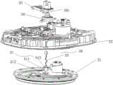
图1示出了根据本发明的电烹饪器具的实施例的局部爆炸示意图;Fig. 1 shows a partial exploded schematic diagram of an embodiment of an electric cooking appliance according to the present invention;
图2示出了图1的内锅盖结构示意图;以及FIG. 2 shows a schematic structural diagram of the inner pot cover of FIG. 1; and
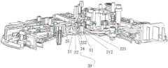
图3示出了图1的局部结构剖面图。FIG. 3 shows a partial structural cross-sectional view of FIG. 1 .
其中,上述附图包括以下附图标记:Wherein, the above-mentioned drawings include the following reference signs:
20、锅盖;21、内锅盖;211、排气口;212、凸台;22、内衬;221、通孔;222、限位部;24、测温盖;241、过线孔;25、转杆;30、测温组件;31、保护壳;311、保护壳主体;312、定位环板;33、测温导线。20, pot lid; 21, inner pot lid; 211, exhaust port; 212, boss; 22, lining; 221, through hole; 222, limit part; 24, temperature measuring cover; 241, wire hole; 25. Rod; 30. Temperature measuring component; 31. Protective shell; 311. Protective shell body; 312. Positioning ring plate; 33. Temperature measuring wire.
具体实施方式Detailed ways
需要说明的是,在不冲突的情况下,本申请中的实施例及实施例中的特征可以相互组合。下面将参考附图并结合实施例来详细说明本发明。It should be noted that the embodiments in the present application and the features of the embodiments may be combined with each other in the case of no conflict. The present invention will be described in detail below with reference to the accompanying drawings and in conjunction with the embodiments.
应该指出,以下详细说明都是例示性的,旨在对本申请提供进一步的说明。除非另有指明,本文使用的所有技术和科学术语具有与本申请所属技术领域的普通技术人员通常理解的相同含义。It should be noted that the following detailed description is exemplary and intended to provide further explanation of the application. Unless otherwise defined, all technical and scientific terms used herein have the same meaning as commonly understood by one of ordinary skill in the art to which this application belongs.
为了便于描述,在这里可以使用空间相对术语,如“在……之上”、“在……上方”、“在……上表面”、“上面的”等,用来描述如在图中所示的一个器件或特征与其他器件或特征的空间位置关系。应当理解的是,空间相对术语旨在包含除了器件在图中所描述的方位之外的在使用或操作中的不同方位。例如,如果附图中的器件被倒置,则描述为“在其他器件或构造上方”或“在其他器件或构造之上”的器件之后将被定位为“在其他器件或构造下方”或“在其他器件或构造之下”。因而,示例性术语“在……上方”可以包括“在……上方”和“在……下方”两种方位。该器件也可以其他不同方式定位(旋转90度或处于其他方位),并且对这里所使用的空间相对描述作出相应解释。For ease of description, spatially relative terms, such as "on", "over", "on the surface", "above", etc., may be used herein to describe what is shown in the figures. The spatial positional relationship of one device or feature shown to other devices or features. It should be understood that spatially relative terms are intended to encompass different orientations of the device in use or operation in addition to the orientation depicted in the figures. For example, if the device in the figures is turned over, elements described as "above" or "over" other devices or features would then be oriented "below" or "over" the other devices or features under other devices or constructions". Thus, the exemplary term "above" can encompass both an orientation of "above" and "below." The device may also be otherwise oriented (rotated 90 degrees or at other orientations) and the spatially relative descriptions used herein interpreted accordingly.
现在,将参照附图更详细地描述根据本申请的示例性实施方式。然而,这些示例性实施方式可以由多种不同的形式来实施,并且不应当被解释为只限于这里所阐述的实施方式。应当理解的是,提供这些实施方式是为了使得本申请的公开彻底且完整,并且将这些示例性实施方式的构思充分传达给本领域普通技术人员,在附图中,为了清楚起见,扩大了层和区域的厚度,并且使用相同的附图标记表示相同的器件,因而将省略对它们的描述。Now, exemplary embodiments according to the present application will be described in more detail with reference to the accompanying drawings. These exemplary embodiments may, however, be embodied in many different forms and should not be construed as limited to the embodiments set forth herein. It should be understood that these embodiments are provided so that this disclosure will be thorough and complete and will fully convey the concept of these exemplary embodiments to those of ordinary skill in the art. In the accompanying drawings, layers are exaggerated for clarity and the thicknesses of the regions, and the same reference numerals are used to denote the same devices, and thus their descriptions will be omitted.
如图1和图2所示,本实施例的一种电烹饪器具,包括:锅体、锅盖20和测温组件30。锅体具有加热装置。锅盖20盖合于锅体上,锅盖20包括由下至上依次设置的内锅盖21、内衬22和面盖,内锅盖21上设置有排气口211。测温组件30与内锅盖21相贴合以测量内锅盖21的温度。测温组件30包括保护壳31和设置在保护壳31内的温度传感器,内锅盖21具有朝向面盖的凸台212,凸台212的上表面高于排气口211,保护壳31与面盖的凸台212相抵接。As shown in FIG. 1 and FIG. 2 , an electric cooking appliance in this embodiment includes a pot body, a
应用本实施例的技术方案,在测温组件30与内锅盖21贴合的位置设置朝向面盖的凸台212,凸台212平面高于排气口211的平面,汤汁和食物由于重力原因会向下移动,这样就避免了汤汁和食物等堆积在测温组件30的保护壳31附近,而导致测温组件30测温不准确。本实施例的技术方案有效地解决了现有技术中汤汁堆积影响测温组件30的测温效果的问题。Applying the technical solution of this embodiment, a
如图3所示,本实施例的电烹饪器具,内衬22上设置有通孔221,保护壳31穿设在通孔221内。这样保护壳31可以穿过通孔221直接与内锅盖21接触,这样测温比较及时、准确。值得注意的是,保护壳31可以保护温度传感器,这样可以延长测温组件30的使用周期。优选地,保护壳31的形状规则,方便与内衬22和内锅盖21配合。As shown in FIG. 3 , in the electric cooking appliance of the present embodiment, a through
如图3所示,本实施例的电烹饪器具,内衬22上设置有限位部222,限位部222与保护壳31相配合以对保护壳31进行限位。限位部222可以防止测温组件30移动,这样温度传感器与内锅盖21上的凸台212贴合紧密,进而保证采温效果。内衬22上设置限位部222比较容易加工、安装方便。As shown in FIG. 3 , in the electric cooking appliance of this embodiment, a limiting
如图3所示,本实施例的电烹饪器具,限位部222设置在内衬22靠近面盖的侧面上。在锅盖20中,内衬22和面盖之间的间隙较大,可以充分利用上述空间设置限位部222,这样的锅盖结构紧凑。As shown in FIG. 3 , in the electric cooking appliance of this embodiment, the limiting
如图3所示,本实施例的电烹饪器具,保护壳31包括保护壳主体311和设置在保护壳主体311外壁上的定位环板312,内衬22的通孔221的直径和保护壳主体311的外径相适配,定位环板312的外径大于内衬22的通孔221。测温组件30的保护壳31一端以定位环板312抵在内衬22上的通孔221一侧,另一端穿过通孔221抵在内锅盖21的凸台212上。弹簧放置在限位部222内部,一端抵在定位环板312上另一端抵在测温盖24上,装配好之后,通过压缩弹簧使测温组件30端部紧贴在凸台212上。定位环板312外径大于通孔221,可以让弹簧有足够的放置平面,同时可以使保护壳31卡在通孔221一端,让它更加稳固,在弹簧压缩的情况下,不容易受力不稳而导致歪斜。当然,保护壳31也可以和凸台212采用粘接的办法。As shown in FIG. 3 , in the electric cooking appliance of this embodiment, the
如图3所示,本实施例的电烹饪器具,限位部222为筒状结构,限位部222的内径与定位环板312的外径相适配。上述尺寸关系可以使定位环板312装配在限位部222中,这样限位部222对保护壳31进行了周向的限位,进而保证了保护壳31在限位部222中不会移动,这样可以保证测温组件30始终和凸台212贴合效果比较好。As shown in FIG. 3 , in the electric cooking appliance of this embodiment, the limiting
如图1和图3所示,本实施例的电烹饪器具,锅盖20还包括测温盖24,测温盖24罩设在保护壳31上方。测温盖24和内衬22相配合起到了保护测温组件30的保护壳31的作用,这样更有利于测温组件30测温的准确性。在锅盖20装配好之后,位于弹簧一端的测温盖24可以使弹簧处于压缩状态,从而使测温组件30紧贴凸台212。As shown in FIG. 1 and FIG. 3 , in the electric cooking appliance of this embodiment, the
如图1所示,本实施例的电烹饪器具,测温组件30还包括测温导线33,测温盖24上设置有过线孔241,测温导线33通过过线孔241穿出。设置过线孔241可以避免线路绕行,使线路布局更加整洁,方便维修。As shown in FIG. 1 , in the electric cooking appliance of this embodiment, the
如图1所示,本实施例的电烹饪器具,锅盖20还包括转杆25,转杆25与测温盖24通过紧固件固定在内衬22上。上述结构使得锅盖20的内部结构紧凑,减少紧固件。固定安装可以避免使用者拆卸之后损坏内部结构,通过紧固件固定,结构也比较简单,方便大批量生产和维修。As shown in FIG. 1 , in the electric cooking appliance of this embodiment, the
本实施例的电烹饪器具为电压力锅或电饭煲。上述的电压力锅或者电饭煲测温精度比较高、测温速度比较快。The electric cooking appliance in this embodiment is an electric pressure cooker or an electric rice cooker. The above-mentioned electric pressure cooker or rice cooker has a relatively high temperature measurement accuracy and a relatively fast temperature measurement speed.
需要注意的是,这里所使用的术语仅是为了描述具体实施方式,而非意图限制根据本申请的示例性实施方式。如在这里所使用的,除非上下文另外明确指出,否则单数形式也意图包括复数形式,此外,还应当理解的是,当在本说明书中使用术语“包含”和/或“包括”时,其指明存在特征、步骤、操作、器件、组件和/或它们的组合。It should be noted that the terminology used herein is for the purpose of describing specific embodiments only, and is not intended to limit the exemplary embodiments according to the present application. As used herein, unless the context clearly dictates otherwise, the singular is intended to include the plural as well, furthermore, it is to be understood that when the terms "comprising" and/or "including" are used in this specification, it indicates that There are features, steps, operations, devices, components and/or combinations thereof.
需要说明的是,本申请的说明书和权利要求书及上述附图中的术语“第一”、“第二”等是用于区别类似的对象,而不必用于描述特定的顺序或先后次序。应该理解这样使用的数据在适当情况下可以互换,以便这里描述的本申请的实施方式例如能够以除了在这里图示或描述的那些以外的顺序实施。此外,术语“包括”和“具有”以及他们的任何变形,意图在于覆盖不排他的包含,例如,包含了一系列步骤或单元的过程、方法、系统、产品或设备不必限于清楚地列出的那些步骤或单元,而是可包括没有清楚地列出的或对于这些过程、方法、产品或设备固有的其它步骤或单元。It should be noted that the terms "first", "second", etc. in the description and claims of the present application and the above drawings are used to distinguish similar objects, and are not necessarily used to describe a specific sequence or sequence. It is to be understood that data so used may be interchanged under appropriate circumstances such that the embodiments of the application described herein can, for example, be practiced in sequences other than those illustrated or described herein. Furthermore, the terms "comprising" and "having" and any variations thereof, are intended to cover non-exclusive inclusion, for example, a process, method, system, product or device comprising a series of steps or units is not necessarily limited to those expressly listed Rather, those steps or units may include other steps or units not expressly listed or inherent to these processes, methods, products or devices.
以上所述仅为本发明的优选实施例而已,并不用于限制本发明,对于本领域的技术人员来说,本发明可以有各种更改和变化。凡在本发明的精神和原则之内,所作的任何修改、等同替换、改进等,均应包含在本发明的保护范围之内。The above descriptions are only preferred embodiments of the present invention, and are not intended to limit the present invention. For those skilled in the art, the present invention may have various modifications and changes. Any modification, equivalent replacement, improvement, etc. made within the spirit and principle of the present invention shall be included within the protection scope of the present invention.
Claims (10)
Priority Applications (1)
| Application Number | Priority Date | Filing Date | Title |
|---|---|---|---|
| CN201810956624.9ACN110840269A (en) | 2018-08-21 | 2018-08-21 | Electric cooking appliance |
Applications Claiming Priority (1)
| Application Number | Priority Date | Filing Date | Title |
|---|---|---|---|
| CN201810956624.9ACN110840269A (en) | 2018-08-21 | 2018-08-21 | Electric cooking appliance |
Publications (1)
| Publication Number | Publication Date |
|---|---|
| CN110840269Atrue CN110840269A (en) | 2020-02-28 |
Family
ID=69595746
Family Applications (1)
| Application Number | Title | Priority Date | Filing Date |
|---|---|---|---|
| CN201810956624.9APendingCN110840269A (en) | 2018-08-21 | 2018-08-21 | Electric cooking appliance |
Country Status (1)
| Country | Link |
|---|---|
| CN (1) | CN110840269A (en) |
Cited By (3)
| Publication number | Priority date | Publication date | Assignee | Title |
|---|---|---|---|---|
| US11134808B2 (en) | 2020-03-30 | 2021-10-05 | Sharkninja Operating Llc | Cooking device and components thereof |
| US11627834B2 (en) | 2017-08-09 | 2023-04-18 | Sharkninja Operating Llc | Cooking system for cooking food |
| US11751710B2 (en) | 2019-02-25 | 2023-09-12 | Sharkninja Operating Llc | Guard for cooking system |
Citations (5)
| Publication number | Priority date | Publication date | Assignee | Title |
|---|---|---|---|---|
| KR101000881B1 (en)* | 2009-06-12 | 2010-12-13 | 쿠쿠전자주식회사 | Cover assembly for cooker |
| CN206772453U (en)* | 2017-04-25 | 2017-12-19 | 浙江绍兴苏泊尔生活电器有限公司 | Cooking utensil |
| CN207370526U (en)* | 2017-04-24 | 2018-05-18 | 浙江绍兴苏泊尔生活电器有限公司 | Cooking utensil |
| CN208957781U (en)* | 2018-08-21 | 2019-06-11 | 浙江绍兴苏泊尔生活电器有限公司 | Cooking utensil |
| CN208957788U (en)* | 2018-08-21 | 2019-06-11 | 浙江绍兴苏泊尔生活电器有限公司 | Electric cooking appliance |
- 2018
- 2018-08-21CNCN201810956624.9Apatent/CN110840269A/enactivePending
Patent Citations (5)
| Publication number | Priority date | Publication date | Assignee | Title |
|---|---|---|---|---|
| KR101000881B1 (en)* | 2009-06-12 | 2010-12-13 | 쿠쿠전자주식회사 | Cover assembly for cooker |
| CN207370526U (en)* | 2017-04-24 | 2018-05-18 | 浙江绍兴苏泊尔生活电器有限公司 | Cooking utensil |
| CN206772453U (en)* | 2017-04-25 | 2017-12-19 | 浙江绍兴苏泊尔生活电器有限公司 | Cooking utensil |
| CN208957781U (en)* | 2018-08-21 | 2019-06-11 | 浙江绍兴苏泊尔生活电器有限公司 | Cooking utensil |
| CN208957788U (en)* | 2018-08-21 | 2019-06-11 | 浙江绍兴苏泊尔生活电器有限公司 | Electric cooking appliance |
Cited By (7)
| Publication number | Priority date | Publication date | Assignee | Title |
|---|---|---|---|---|
| US11627834B2 (en) | 2017-08-09 | 2023-04-18 | Sharkninja Operating Llc | Cooking system for cooking food |
| US11751710B2 (en) | 2019-02-25 | 2023-09-12 | Sharkninja Operating Llc | Guard for cooking system |
| US12226039B2 (en) | 2019-02-25 | 2025-02-18 | Sharkninja Operating Llc | Guard for cooking system |
| US11134808B2 (en) | 2020-03-30 | 2021-10-05 | Sharkninja Operating Llc | Cooking device and components thereof |
| US11647861B2 (en) | 2020-03-30 | 2023-05-16 | Sharkninja Operating Llc | Cooking device and components thereof |
| US11678765B2 (en) | 2020-03-30 | 2023-06-20 | Sharkninja Operating Llc | Cooking device and components thereof |
| US11969118B2 (en) | 2020-03-30 | 2024-04-30 | Sharkninja Operating Llc | Cooking device and components thereof |
Similar Documents
| Publication | Publication Date | Title |
|---|---|---|
| CN103169366B (en) | It is provided with the foot cooking vessel of heat indicator | |
| US20210180797A1 (en) | Cooking appliance accessory and method of use | |
| CN110840269A (en) | Electric cooking appliance | |
| US20190357319A1 (en) | Sensor system for temperature-regulating appliance | |
| CN208957797U (en) | Temperature sensor and heating instrument assemblies | |
| CN204698382U (en) | Steam valve, upper cover and cooking apparatus | |
| CN109380983B (en) | A cooking utensil | |
| CN203837045U (en) | Induction cooker | |
| CN206560365U (en) | High speed broken wall cooking machine | |
| CN208170456U (en) | Electromagnetic cooking set | |
| CN204698317U (en) | Outer pot assembly and cooking apparatus | |
| CN208447284U (en) | Electric cooker with Novel temperature sensing device | |
| CN204274116U (en) | Apparatus for heating food | |
| CN204483921U (en) | Temperature sensing device and use this temperature sensing device decoct roasting machine | |
| CN209404367U (en) | a cooking utensil | |
| CN203555530U (en) | Electric heat pot with safe temperature measuring function | |
| CN205322085U (en) | Double -layer water jug | |
| CN216628244U (en) | Temperature probe structure convenient to equipment and use its electromagnetism cooking utensil | |
| CN205942478U (en) | Electric heat cooking utensil temperature regulating device and electric heat cooking utensil thereof | |
| CN204427775U (en) | Temperature controller component and electric pressure cooking saucepan | |
| CN208957788U (en) | Electric cooking appliance | |
| CN201096535Y (en) | Sensitive and accurate electric-heating cooking utensil temperature sensing device | |
| CN208286881U (en) | Interior pot and cooking apparatus | |
| CN211976946U (en) | Temperature sensing structure of electric heater | |
| CN206761527U (en) | cooking utensils |
Legal Events
| Date | Code | Title | Description |
|---|---|---|---|
| PB01 | Publication | ||
| PB01 | Publication | ||
| SE01 | Entry into force of request for substantive examination | ||
| SE01 | Entry into force of request for substantive examination | ||
| RJ01 | Rejection of invention patent application after publication | ||
| RJ01 | Rejection of invention patent application after publication | Application publication date:20200228 |