CN110838458B - Semiconductor processing system and method - Google Patents
Semiconductor processing system and methodDownload PDFInfo
- Publication number
- CN110838458B CN110838458BCN201910764658.2ACN201910764658ACN110838458BCN 110838458 BCN110838458 BCN 110838458BCN 201910764658 ACN201910764658 ACN 201910764658ACN 110838458 BCN110838458 BCN 110838458B
- Authority
- CN
- China
- Prior art keywords
- gas distributor
- chamber
- semiconductor processing
- suction seat
- screwless
- Prior art date
- Legal status (The legal status is an assumption and is not a legal conclusion. Google has not performed a legal analysis and makes no representation as to the accuracy of the status listed.)
- Active
Links
- 239000004065semiconductorSubstances0.000titleclaimsabstractdescription77
- 238000012545processingMethods0.000titleclaimsdescription23
- 238000000034methodMethods0.000titleabstractdescription44
- 230000005686electrostatic fieldEffects0.000claimsdescription7
- 238000003672processing methodMethods0.000claimsdescription7
- 238000001746injection mouldingMethods0.000claimsdescription6
- 230000036632reaction speedEffects0.000claimsdescription2
- 230000001939inductive effectEffects0.000claims1
- 239000007789gasSubstances0.000description185
- 238000000429assemblyMethods0.000description41
- 230000000712assemblyEffects0.000description41
- 235000012431wafersNutrition0.000description35
- 210000002105tongueAnatomy0.000description19
- 230000006870functionEffects0.000description16
- 239000000758substrateSubstances0.000description7
- 239000000126substanceSubstances0.000description6
- 238000002347injectionMethods0.000description5
- 239000007924injectionSubstances0.000description5
- 238000000231atomic layer depositionMethods0.000description4
- 238000005229chemical vapour depositionMethods0.000description4
- 238000010586diagramMethods0.000description4
- 238000004519manufacturing processMethods0.000description4
- 238000005240physical vapour depositionMethods0.000description4
- 238000000663remote plasma-enhanced chemical vapour depositionMethods0.000description4
- 238000003860storageMethods0.000description4
- 238000013461designMethods0.000description3
- 239000007788liquidSubstances0.000description3
- 238000012986modificationMethods0.000description3
- 230000004048modificationEffects0.000description3
- 238000005234chemical depositionMethods0.000description2
- 238000009826distributionMethods0.000description2
- 238000005516engineering processMethods0.000description2
- 238000005530etchingMethods0.000description2
- 239000004973liquid crystal related substanceSubstances0.000description2
- 238000003466weldingMethods0.000description2
- XUIMIQQOPSSXEZ-UHFFFAOYSA-NSiliconChemical compound[Si]XUIMIQQOPSSXEZ-UHFFFAOYSA-N0.000description1
- 239000002131composite materialSubstances0.000description1
- 238000007796conventional methodMethods0.000description1
- 238000011161developmentMethods0.000description1
- 239000011521glassSubstances0.000description1
- 230000005484gravityEffects0.000description1
- 230000010354integrationEffects0.000description1
- 239000000463materialSubstances0.000description1
- 239000003595mistSubstances0.000description1
- 229910052710siliconInorganic materials0.000description1
- 239000010703siliconSubstances0.000description1
- 238000004088simulationMethods0.000description1
- 238000006467substitution reactionMethods0.000description1
Images


Classifications
- H—ELECTRICITY
- H01—ELECTRIC ELEMENTS
- H01J—ELECTRIC DISCHARGE TUBES OR DISCHARGE LAMPS
- H01J37/00—Discharge tubes with provision for introducing objects or material to be exposed to the discharge, e.g. for the purpose of examination or processing thereof
- H01J37/32—Gas-filled discharge tubes
- H01J37/32431—Constructional details of the reactor
- H01J37/3244—Gas supply means
- H—ELECTRICITY
- H01—ELECTRIC ELEMENTS
- H01L—SEMICONDUCTOR DEVICES NOT COVERED BY CLASS H10
- H01L21/00—Processes or apparatus adapted for the manufacture or treatment of semiconductor or solid state devices or of parts thereof
- H01L21/67—Apparatus specially adapted for handling semiconductor or electric solid state devices during manufacture or treatment thereof; Apparatus specially adapted for handling wafers during manufacture or treatment of semiconductor or electric solid state devices or components ; Apparatus not specifically provided for elsewhere
- H01L21/67005—Apparatus not specifically provided for elsewhere
- H01L21/67011—Apparatus for manufacture or treatment
- C—CHEMISTRY; METALLURGY
- C23—COATING METALLIC MATERIAL; COATING MATERIAL WITH METALLIC MATERIAL; CHEMICAL SURFACE TREATMENT; DIFFUSION TREATMENT OF METALLIC MATERIAL; COATING BY VACUUM EVAPORATION, BY SPUTTERING, BY ION IMPLANTATION OR BY CHEMICAL VAPOUR DEPOSITION, IN GENERAL; INHIBITING CORROSION OF METALLIC MATERIAL OR INCRUSTATION IN GENERAL
- C23C—COATING METALLIC MATERIAL; COATING MATERIAL WITH METALLIC MATERIAL; SURFACE TREATMENT OF METALLIC MATERIAL BY DIFFUSION INTO THE SURFACE, BY CHEMICAL CONVERSION OR SUBSTITUTION; COATING BY VACUUM EVAPORATION, BY SPUTTERING, BY ION IMPLANTATION OR BY CHEMICAL VAPOUR DEPOSITION, IN GENERAL
- C23C14/00—Coating by vacuum evaporation, by sputtering or by ion implantation of the coating forming material
- C23C14/22—Coating by vacuum evaporation, by sputtering or by ion implantation of the coating forming material characterised by the process of coating
- C23C14/50—Substrate holders
- C—CHEMISTRY; METALLURGY
- C23—COATING METALLIC MATERIAL; COATING MATERIAL WITH METALLIC MATERIAL; CHEMICAL SURFACE TREATMENT; DIFFUSION TREATMENT OF METALLIC MATERIAL; COATING BY VACUUM EVAPORATION, BY SPUTTERING, BY ION IMPLANTATION OR BY CHEMICAL VAPOUR DEPOSITION, IN GENERAL; INHIBITING CORROSION OF METALLIC MATERIAL OR INCRUSTATION IN GENERAL
- C23C—COATING METALLIC MATERIAL; COATING MATERIAL WITH METALLIC MATERIAL; SURFACE TREATMENT OF METALLIC MATERIAL BY DIFFUSION INTO THE SURFACE, BY CHEMICAL CONVERSION OR SUBSTITUTION; COATING BY VACUUM EVAPORATION, BY SPUTTERING, BY ION IMPLANTATION OR BY CHEMICAL VAPOUR DEPOSITION, IN GENERAL
- C23C14/00—Coating by vacuum evaporation, by sputtering or by ion implantation of the coating forming material
- C23C14/22—Coating by vacuum evaporation, by sputtering or by ion implantation of the coating forming material characterised by the process of coating
- C23C14/56—Apparatus specially adapted for continuous coating; Arrangements for maintaining the vacuum, e.g. vacuum locks
- C23C14/564—Means for minimising impurities in the coating chamber such as dust, moisture, residual gases
- C—CHEMISTRY; METALLURGY
- C23—COATING METALLIC MATERIAL; COATING MATERIAL WITH METALLIC MATERIAL; CHEMICAL SURFACE TREATMENT; DIFFUSION TREATMENT OF METALLIC MATERIAL; COATING BY VACUUM EVAPORATION, BY SPUTTERING, BY ION IMPLANTATION OR BY CHEMICAL VAPOUR DEPOSITION, IN GENERAL; INHIBITING CORROSION OF METALLIC MATERIAL OR INCRUSTATION IN GENERAL
- C23C—COATING METALLIC MATERIAL; COATING MATERIAL WITH METALLIC MATERIAL; SURFACE TREATMENT OF METALLIC MATERIAL BY DIFFUSION INTO THE SURFACE, BY CHEMICAL CONVERSION OR SUBSTITUTION; COATING BY VACUUM EVAPORATION, BY SPUTTERING, BY ION IMPLANTATION OR BY CHEMICAL VAPOUR DEPOSITION, IN GENERAL
- C23C16/00—Chemical coating by decomposition of gaseous compounds, without leaving reaction products of surface material in the coating, i.e. chemical vapour deposition [CVD] processes
- C23C16/44—Chemical coating by decomposition of gaseous compounds, without leaving reaction products of surface material in the coating, i.e. chemical vapour deposition [CVD] processes characterised by the method of coating
- C23C16/4401—Means for minimising impurities, e.g. dust, moisture or residual gas, in the reaction chamber
- C—CHEMISTRY; METALLURGY
- C23—COATING METALLIC MATERIAL; COATING MATERIAL WITH METALLIC MATERIAL; CHEMICAL SURFACE TREATMENT; DIFFUSION TREATMENT OF METALLIC MATERIAL; COATING BY VACUUM EVAPORATION, BY SPUTTERING, BY ION IMPLANTATION OR BY CHEMICAL VAPOUR DEPOSITION, IN GENERAL; INHIBITING CORROSION OF METALLIC MATERIAL OR INCRUSTATION IN GENERAL
- C23C—COATING METALLIC MATERIAL; COATING MATERIAL WITH METALLIC MATERIAL; SURFACE TREATMENT OF METALLIC MATERIAL BY DIFFUSION INTO THE SURFACE, BY CHEMICAL CONVERSION OR SUBSTITUTION; COATING BY VACUUM EVAPORATION, BY SPUTTERING, BY ION IMPLANTATION OR BY CHEMICAL VAPOUR DEPOSITION, IN GENERAL
- C23C16/00—Chemical coating by decomposition of gaseous compounds, without leaving reaction products of surface material in the coating, i.e. chemical vapour deposition [CVD] processes
- C23C16/44—Chemical coating by decomposition of gaseous compounds, without leaving reaction products of surface material in the coating, i.e. chemical vapour deposition [CVD] processes characterised by the method of coating
- C23C16/458—Chemical coating by decomposition of gaseous compounds, without leaving reaction products of surface material in the coating, i.e. chemical vapour deposition [CVD] processes characterised by the method of coating characterised by the method used for supporting substrates in the reaction chamber
- C23C16/4582—Rigid and flat substrates, e.g. plates or discs
- C23C16/4583—Rigid and flat substrates, e.g. plates or discs the substrate being supported substantially horizontally
- C23C16/4586—Elements in the interior of the support, e.g. electrodes, heating or cooling devices
- H—ELECTRICITY
- H01—ELECTRIC ELEMENTS
- H01J—ELECTRIC DISCHARGE TUBES OR DISCHARGE LAMPS
- H01J37/00—Discharge tubes with provision for introducing objects or material to be exposed to the discharge, e.g. for the purpose of examination or processing thereof
- H01J37/32—Gas-filled discharge tubes
- H01J37/32431—Constructional details of the reactor
- H01J37/32715—Workpiece holder
- H—ELECTRICITY
- H01—ELECTRIC ELEMENTS
- H01L—SEMICONDUCTOR DEVICES NOT COVERED BY CLASS H10
- H01L21/00—Processes or apparatus adapted for the manufacture or treatment of semiconductor or solid state devices or of parts thereof
- H01L21/67—Apparatus specially adapted for handling semiconductor or electric solid state devices during manufacture or treatment thereof; Apparatus specially adapted for handling wafers during manufacture or treatment of semiconductor or electric solid state devices or components ; Apparatus not specifically provided for elsewhere
- H01L21/683—Apparatus specially adapted for handling semiconductor or electric solid state devices during manufacture or treatment thereof; Apparatus specially adapted for handling wafers during manufacture or treatment of semiconductor or electric solid state devices or components ; Apparatus not specifically provided for elsewhere for supporting or gripping
- H01L21/6831—Apparatus specially adapted for handling semiconductor or electric solid state devices during manufacture or treatment thereof; Apparatus specially adapted for handling wafers during manufacture or treatment of semiconductor or electric solid state devices or components ; Apparatus not specifically provided for elsewhere for supporting or gripping using electrostatic chucks
- H—ELECTRICITY
- H01—ELECTRIC ELEMENTS
- H01L—SEMICONDUCTOR DEVICES NOT COVERED BY CLASS H10
- H01L21/00—Processes or apparatus adapted for the manufacture or treatment of semiconductor or solid state devices or of parts thereof
- H01L21/67—Apparatus specially adapted for handling semiconductor or electric solid state devices during manufacture or treatment thereof; Apparatus specially adapted for handling wafers during manufacture or treatment of semiconductor or electric solid state devices or components ; Apparatus not specifically provided for elsewhere
- H01L21/683—Apparatus specially adapted for handling semiconductor or electric solid state devices during manufacture or treatment thereof; Apparatus specially adapted for handling wafers during manufacture or treatment of semiconductor or electric solid state devices or components ; Apparatus not specifically provided for elsewhere for supporting or gripping
- H01L21/687—Apparatus specially adapted for handling semiconductor or electric solid state devices during manufacture or treatment thereof; Apparatus specially adapted for handling wafers during manufacture or treatment of semiconductor or electric solid state devices or components ; Apparatus not specifically provided for elsewhere for supporting or gripping using mechanical means, e.g. chucks, clamps or pinches
- H01L21/68714—Apparatus specially adapted for handling semiconductor or electric solid state devices during manufacture or treatment thereof; Apparatus specially adapted for handling wafers during manufacture or treatment of semiconductor or electric solid state devices or components ; Apparatus not specifically provided for elsewhere for supporting or gripping using mechanical means, e.g. chucks, clamps or pinches the wafers being placed on a susceptor, stage or support
- H01L21/68721—Apparatus specially adapted for handling semiconductor or electric solid state devices during manufacture or treatment thereof; Apparatus specially adapted for handling wafers during manufacture or treatment of semiconductor or electric solid state devices or components ; Apparatus not specifically provided for elsewhere for supporting or gripping using mechanical means, e.g. chucks, clamps or pinches the wafers being placed on a susceptor, stage or support characterised by edge clamping, e.g. clamping ring
- H—ELECTRICITY
- H01—ELECTRIC ELEMENTS
- H01L—SEMICONDUCTOR DEVICES NOT COVERED BY CLASS H10
- H01L21/00—Processes or apparatus adapted for the manufacture or treatment of semiconductor or solid state devices or of parts thereof
- H01L21/67—Apparatus specially adapted for handling semiconductor or electric solid state devices during manufacture or treatment thereof; Apparatus specially adapted for handling wafers during manufacture or treatment of semiconductor or electric solid state devices or components ; Apparatus not specifically provided for elsewhere
- H01L21/683—Apparatus specially adapted for handling semiconductor or electric solid state devices during manufacture or treatment thereof; Apparatus specially adapted for handling wafers during manufacture or treatment of semiconductor or electric solid state devices or components ; Apparatus not specifically provided for elsewhere for supporting or gripping
- H01L21/687—Apparatus specially adapted for handling semiconductor or electric solid state devices during manufacture or treatment thereof; Apparatus specially adapted for handling wafers during manufacture or treatment of semiconductor or electric solid state devices or components ; Apparatus not specifically provided for elsewhere for supporting or gripping using mechanical means, e.g. chucks, clamps or pinches
- H01L21/68714—Apparatus specially adapted for handling semiconductor or electric solid state devices during manufacture or treatment thereof; Apparatus specially adapted for handling wafers during manufacture or treatment of semiconductor or electric solid state devices or components ; Apparatus not specifically provided for elsewhere for supporting or gripping using mechanical means, e.g. chucks, clamps or pinches the wafers being placed on a susceptor, stage or support
- H01L21/68785—Apparatus specially adapted for handling semiconductor or electric solid state devices during manufacture or treatment thereof; Apparatus specially adapted for handling wafers during manufacture or treatment of semiconductor or electric solid state devices or components ; Apparatus not specifically provided for elsewhere for supporting or gripping using mechanical means, e.g. chucks, clamps or pinches the wafers being placed on a susceptor, stage or support characterised by the mechanical construction of the susceptor, stage or support
- C—CHEMISTRY; METALLURGY
- C23—COATING METALLIC MATERIAL; COATING MATERIAL WITH METALLIC MATERIAL; CHEMICAL SURFACE TREATMENT; DIFFUSION TREATMENT OF METALLIC MATERIAL; COATING BY VACUUM EVAPORATION, BY SPUTTERING, BY ION IMPLANTATION OR BY CHEMICAL VAPOUR DEPOSITION, IN GENERAL; INHIBITING CORROSION OF METALLIC MATERIAL OR INCRUSTATION IN GENERAL
- C23C—COATING METALLIC MATERIAL; COATING MATERIAL WITH METALLIC MATERIAL; SURFACE TREATMENT OF METALLIC MATERIAL BY DIFFUSION INTO THE SURFACE, BY CHEMICAL CONVERSION OR SUBSTITUTION; COATING BY VACUUM EVAPORATION, BY SPUTTERING, BY ION IMPLANTATION OR BY CHEMICAL VAPOUR DEPOSITION, IN GENERAL
- C23C16/00—Chemical coating by decomposition of gaseous compounds, without leaving reaction products of surface material in the coating, i.e. chemical vapour deposition [CVD] processes
- C23C16/44—Chemical coating by decomposition of gaseous compounds, without leaving reaction products of surface material in the coating, i.e. chemical vapour deposition [CVD] processes characterised by the method of coating
- C23C16/455—Chemical coating by decomposition of gaseous compounds, without leaving reaction products of surface material in the coating, i.e. chemical vapour deposition [CVD] processes characterised by the method of coating characterised by the method used for introducing gases into reaction chamber or for modifying gas flows in reaction chamber
- C23C16/45563—Gas nozzles
- C23C16/45565—Shower nozzles
- H—ELECTRICITY
- H01—ELECTRIC ELEMENTS
- H01L—SEMICONDUCTOR DEVICES NOT COVERED BY CLASS H10
- H01L21/00—Processes or apparatus adapted for the manufacture or treatment of semiconductor or solid state devices or of parts thereof
- H01L21/67—Apparatus specially adapted for handling semiconductor or electric solid state devices during manufacture or treatment thereof; Apparatus specially adapted for handling wafers during manufacture or treatment of semiconductor or electric solid state devices or components ; Apparatus not specifically provided for elsewhere
- H01L21/683—Apparatus specially adapted for handling semiconductor or electric solid state devices during manufacture or treatment thereof; Apparatus specially adapted for handling wafers during manufacture or treatment of semiconductor or electric solid state devices or components ; Apparatus not specifically provided for elsewhere for supporting or gripping
- H01L21/6831—Apparatus specially adapted for handling semiconductor or electric solid state devices during manufacture or treatment thereof; Apparatus specially adapted for handling wafers during manufacture or treatment of semiconductor or electric solid state devices or components ; Apparatus not specifically provided for elsewhere for supporting or gripping using electrostatic chucks
- H01L21/6833—Details of electrostatic chucks
- H—ELECTRICITY
- H01—ELECTRIC ELEMENTS
- H01L—SEMICONDUCTOR DEVICES NOT COVERED BY CLASS H10
- H01L21/00—Processes or apparatus adapted for the manufacture or treatment of semiconductor or solid state devices or of parts thereof
- H01L21/67—Apparatus specially adapted for handling semiconductor or electric solid state devices during manufacture or treatment thereof; Apparatus specially adapted for handling wafers during manufacture or treatment of semiconductor or electric solid state devices or components ; Apparatus not specifically provided for elsewhere
- H01L21/683—Apparatus specially adapted for handling semiconductor or electric solid state devices during manufacture or treatment thereof; Apparatus specially adapted for handling wafers during manufacture or treatment of semiconductor or electric solid state devices or components ; Apparatus not specifically provided for elsewhere for supporting or gripping
- H01L21/6838—Apparatus specially adapted for handling semiconductor or electric solid state devices during manufacture or treatment thereof; Apparatus specially adapted for handling wafers during manufacture or treatment of semiconductor or electric solid state devices or components ; Apparatus not specifically provided for elsewhere for supporting or gripping with gripping and holding devices using a vacuum; Bernoulli devices
- H—ELECTRICITY
- H01—ELECTRIC ELEMENTS
- H01L—SEMICONDUCTOR DEVICES NOT COVERED BY CLASS H10
- H01L21/00—Processes or apparatus adapted for the manufacture or treatment of semiconductor or solid state devices or of parts thereof
- H01L21/70—Manufacture or treatment of devices consisting of a plurality of solid state components formed in or on a common substrate or of parts thereof; Manufacture of integrated circuit devices or of parts thereof
- H01L21/71—Manufacture of specific parts of devices defined in group H01L21/70
- H01L21/768—Applying interconnections to be used for carrying current between separate components within a device comprising conductors and dielectrics
- H01L21/76838—Applying interconnections to be used for carrying current between separate components within a device comprising conductors and dielectrics characterised by the formation and the after-treatment of the conductors
- H01L21/76841—Barrier, adhesion or liner layers
- H01L21/76853—Barrier, adhesion or liner layers characterized by particular after-treatment steps
- H01L21/76855—After-treatment introducing at least one additional element into the layer
- H01L21/76856—After-treatment introducing at least one additional element into the layer by treatment in plasmas or gaseous environments, e.g. nitriding a refractory metal liner
Landscapes
- Engineering & Computer Science (AREA)
- Chemical & Material Sciences (AREA)
- Physics & Mathematics (AREA)
- Condensed Matter Physics & Semiconductors (AREA)
- General Physics & Mathematics (AREA)
- Manufacturing & Machinery (AREA)
- Computer Hardware Design (AREA)
- Microelectronics & Electronic Packaging (AREA)
- Power Engineering (AREA)
- Chemical Kinetics & Catalysis (AREA)
- Materials Engineering (AREA)
- Mechanical Engineering (AREA)
- Metallurgy (AREA)
- Organic Chemistry (AREA)
- General Chemical & Material Sciences (AREA)
- Analytical Chemistry (AREA)
- Plasma & Fusion (AREA)
- Container, Conveyance, Adherence, Positioning, Of Wafer (AREA)
Abstract
Translated fromChinese
Description
Translated fromChinese技术领域technical field
本公开实施例涉及一种半导体制程系统以及方法。Embodiments of the present disclosure relate to a semiconductor manufacturing system and method.
背景技术Background technique
随着电子产品的发展,半导体技术已广泛应用于制造存储器(memory)、中央处理器(central processing units,CPU)、液晶显示器(liquid crystal displays,LCD)、发光二极管(light emission diodes,LED)、激光二极管(laser diodes)和其他装置或芯片组。为了实现高的整合度和高的速度要求,已经降低了半导体集成电路的尺寸,并且已经提出了各种材料和技术来实现这些要求并克服制造期间的障碍。对腔室内的晶圆加工条件进行控制是半导体制造技术的重要部分。With the development of electronic products, semiconductor technology has been widely used in the manufacture of memory, central processing units (CPU), liquid crystal displays (LCD), light-emitting diodes (LED), Laser diodes and other devices or chipsets. In order to achieve high integration and high speed requirements, the size of semiconductor integrated circuits has been reduced, and various materials and techniques have been proposed to achieve these requirements and overcome obstacles during fabrication. Controlling wafer processing conditions in a chamber is an important part of semiconductor manufacturing technology.
通常是使用螺丝来组装腔室的元件。然而,在锁紧和松开螺丝期间可能会损坏使用螺丝来组装的腔室元件。此外,螺丝本身可能会因使用而损坏,并可能随着时间而腐蚀。因此,用于腔室元件组装的传统技术并不完全令人满意。The components of the chamber are usually assembled using screws. However, the chamber elements assembled using the screws may be damaged during the tightening and loosening of the screws. Also, the screws themselves can be damaged with use and can corrode over time. Therefore, conventional techniques for chamber element assembly are not entirely satisfactory.
发明内容SUMMARY OF THE INVENTION
在一些实施例中提供一种半导体制程系统,包括:气体分配器组件,配置以在腔室内分配气体;以及吸座组件,配置以在腔室内固定晶圆,其中气体分配器组件以及吸座组件的至少一者包括具有凸起突出部的第一部分以及具有凹陷开口的第二部分,凸起突出部是配置以进入凹陷开口。In some embodiments there is provided a semiconductor processing system comprising: a gas distributor assembly configured to distribute a gas within a chamber; and a suction seat assembly configured to hold a wafer within the chamber, wherein the gas distributor assembly and the suction seat assembly At least one of the includes a first portion having a raised protrusion and a second portion having a recessed opening, the raised protrusion being configured to enter the recessed opening.
在一些实施例中提供一种半导体制程系统,包括气体分配器组件以及吸座组件。气体分配器组件配置以在腔室中分配气体,气体分配器组件包括具有凸起突出部的第一气体分配器部分、以及具有凹陷开口的第二气体分配器部分,凸起突出部是配置以进入凹陷开口。吸座组件配置以在腔室中固定晶圆,吸座组件位于气体分配器组件下方。In some embodiments, a semiconductor processing system is provided that includes a gas distributor assembly and a suction seat assembly. A gas distributor assembly is configured to distribute gas in the chamber, the gas distributor assembly includes a first gas distributor portion having a raised protrusion, and a second gas distributor portion having a recessed opening, the raised protrusion being configured to into the recessed opening. A suction seat assembly is configured to hold the wafer in the chamber, and the suction seat assembly is located below the gas distributor assembly.
在一些实施例中提供一种半导体制程方法,包括:构建包括凸起突出部的第一部分;构建包括凹陷开口的第二部分,第一部分及第二部分是为以下两者的一部分:配置以在腔室中分配气体的气体分配器组件,或配置以在腔室中固定晶圆的吸座组件;以及将凸起突出部放置在凹陷开口中。In some embodiments, a semiconductor processing method is provided, comprising: building a first portion including a raised protrusion; building a second portion including a recessed opening, the first portion and the second portion being part of: a gas distributor assembly for distributing gas in the chamber, or a suction seat assembly configured to hold the wafer in the chamber; and placing the raised tabs in the recessed openings.
附图说明Description of drawings
以下将配合说明书附图详述本公开的实施例。应注意的是,依据在业界的标准做法,多种特征并未按照比例示出且仅用以说明例示。事实上,可能任意地放大或缩小元件的尺寸,以清楚地表现出本公开的特征。The embodiments of the present disclosure will be described in detail below with reference to the accompanying drawings. It should be noted that, in accordance with standard practice in the industry, various features are not shown to scale and are for illustrative purposes only. In fact, the dimensions of elements may be arbitrarily enlarged or reduced to clearly represent the features of the present disclosure.
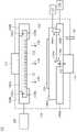
图1是根据一些实施例的具有无螺丝气体分配器组件和无螺丝吸座组件的无螺丝半导体处理腔室的侧视图。1 is a side view of a screwless semiconductor processing chamber having a screwless gas distributor assembly and a screwless suction mount assembly, according to some embodiments.
图2A是根据一些实施例的第一气体分配器部分的侧视图。2A is a side view of a first gas distributor portion in accordance with some embodiments.
图2B是根据一些实施例的第一气体分配器部分的平面图。2B is a plan view of a first gas distributor portion in accordance with some embodiments.
图3A是根据一些实施例的第二气体分配器部分的侧视图。3A is a side view of a second gas distributor portion in accordance with some embodiments.
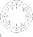
图3B根据一些实施例的处于拆卸形式的第二气体分配器部分的平面图。3B is a plan view of the second gas distributor portion in disassembled form, according to some embodiments.
图4是根据一些实施例的与第一气体分配器部分组装的第二气体分配器部分的剖面图。4 is a cross-sectional view of a second gas distributor portion assembled with the first gas distributor portion, according to some embodiments.
图5A是根据一些实施例的第一吸座部分的侧视图。5A is a side view of a first suction seat portion in accordance with some embodiments.
图5B是根据一些实施例的第二吸座部分的侧视图。5B is a side view of a second suction seat portion in accordance with some embodiments.
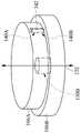
图6A是根据一些实施例的处于拆卸形式的第一吸座部分和第二吸座部分的立体图。6A is a perspective view of the first suction seat portion and the second suction seat portion in disassembled form, according to some embodiments.
图6B是根据一些实施例的处于组装形式的第一吸座部分和第二吸座部分的立体图。6B is a perspective view of the first suction seat portion and the second suction seat portion in an assembled form, according to some embodiments.
图7是根据一些实施例的无螺丝半导体腔室的无螺丝半导体腔室功能模块的方框图。7 is a block diagram of a screwless semiconductor chamber functional module of a screwless semiconductor chamber in accordance with some embodiments.
图8是根据一些实施例的无螺丝半导体腔室制程的流程图。8 is a flow diagram of a screwless semiconductor chamber process according to some embodiments.
附图标记说明:Description of reference numbers:
102无螺丝半导体制程腔室102 screwless semiconductor process chamber
104A 无螺丝气体分配器组件(第一气体分配器部分)104A Screwless Gas Distributor Assembly (First Gas Distributor Part)
104B 无螺丝气体分配器组件(第二气体分配器部分)104B Screwless Gas Distributor Assembly (Second Gas Distributor Part)
106A 无螺丝吸座组件(第一吸座部分)106A Screwless suction seat assembly (first suction seat part)
106B 无螺丝吸座组件(第二吸座部分)106B Screwless suction seat assembly (second suction seat part)
108 电源108 Power
110 支撑器110 Support
112 导管112 Catheter
114 外壳114 Shell
116 壁116 Walls
120 气体120 Gas
124 开口124 openings
126 晶圆126 wafers
127 第一吸座部分电源127 Partial power supply of the first suction seat
128 第二吸座部分电源128 Partial power supply of the second suction seat
130 导管130 Conduit
130A 第一吸座部分凸起突出部130A First suction seat part raised protrusion
130B 第二吸座部分凹陷开口130B The second suction seat part is recessed and opened
132 中心轴132 Center shaft
140A 第一定位销凹面140A 1st locating pin concave
140B 第二定位销凹面140B Second locating pin concave
150A 第一气体分配器部分凸起突出部150A First Gas Distributor Section Raised Tab
150B 第二气体分配器部分凹陷开口150B Second gas distributor partially recessed opening
158A 顶部158A top
158B 底部158B Bottom
159A 水平轴159A Horizontal axis
159B 垂直轴159B Vertical axis
160A、160B、160C、160D 部件160A, 160B, 160C, 160D Parts
702 无螺丝半导体腔室功能模块702 Screwless Semiconductor Chamber Function Module
704 处理器704 processor
706 电脑可读取存储模块706 Computer-readable storage module
708 控制器模块708 Controller Module
710 使用者界面模块710 User Interface Module
712 控制器模块712 Controller Module
800 制程800 process
802、804、806、808、810、812、814、816 操作802, 804, 806, 808, 810, 812, 814, 816 operations
具体实施方式Detailed ways
应理解的是,以下公开许多不同的实施方法或是范例来实行所提供的标的的不同特征,以下描述具体的元件及其排列的实施例以阐述本公开。当然这些实施例仅用以例示,且不该以此限定本公开的范围。举例来说,应理解的是,当元件被称为“连接到”或“耦接到”另一个元件时,其可直接连接到或耦接到另一个元件,或亦可存在一或多个中间的元件。It should be understood that many different implementations or examples are disclosed below for carrying out the various features of the presented subject matter, and examples of specific elements and arrangements thereof are described below to illustrate the present disclosure. Of course, these examples are for illustration only, and should not limit the scope of the present disclosure. For example, it will be understood that when an element is referred to as being "connected" or "coupled" to another element, it can be directly connected or coupled to the other element, or one or more may also be present middle element.
此外,在不同实施例中可能使用重复的标号或标示,这些重复仅为了简单清楚地叙述本发明,不代表所讨论的不同实施例及/或结构之间有特定的关系。Furthermore, repeated reference numerals or designations may be used in different embodiments, such repetitions are merely for simplicity and clarity to describe the present invention and do not represent a specific relationship between the different embodiments and/or structures discussed.
此外,其中可能用到与空间相关用词,例如“在……下方”、“下方”、“较低的”、“上方”、“较高的”及类似的用词,这些空间相关用词是为了便于描述图示中一个(些)元件或特征与另一个(些)元件或特征之间的关系,这些空间相关用词包括使用中或操作中的装置的不同方位,以及附图中所描述的方位。当装置被转向不同方位时(旋转90度或其他方位),则其中所使用的空间相关形容词也将依转向后的方位来解释。In addition, spatially relative terms such as "below", "below", "lower", "above", "higher" and similar terms may be used therein, which For convenience in describing the relationship between one element or feature(s) and another element or feature(s) in the figures, these spatially relative terms include different orientations of the device in use or operation, and the described orientation. When the device is turned in a different orientation (rotated 90 degrees or otherwise), the spatially relative adjectives used therein will also be interpreted according to the turned orientation.
根据一些实施例的系统和方法涉及一种无螺丝半导体腔室(screwlesssemiconductor chamber)。无螺丝半导体腔室是具有不使用螺丝或钉子来将分开的部件组装在一起的半导体腔室。反之,各个部件能够通过部件本身的各种轮廓和特征组装在一起。在一些实施例中,各种部件可藉助于重力及/或以非刚性方式提供附接的特定部分(例如不使用螺丝或钉子),以利用部件上的各种轮廓和特征组装在一起。举例来说,半导体腔室的各个部分可以利用例如榫眼(mortise joint)、榫接头(tenon joint)、内螺旋(innerspiral)、定位销(location pinning)、按扣(snap)及/或结构块件(building block)而组装在一起。Systems and methods according to some embodiments relate to a screwless semiconductor chamber. A screwless semiconductor chamber is a semiconductor chamber that does not use screws or nails to assemble separate components together. Rather, the individual components can be assembled together through various contours and features of the components themselves. In some embodiments, the various components may be assembled together using various contours and features on the components by gravity and/or by providing certain portions of attachment in a non-rigid manner (eg, without the use of screws or nails). For example, various parts of the semiconductor chamber may utilize, for example, mortise joints, tenon joints, inner spirals, location pinnings, snaps and/or structural blocks assembled together as building blocks.
在一些实施例中,无螺丝半导体腔室的某些部分可为无螺丝的或者可在没有螺丝或钉子的情况下进行组装,而无螺丝半导体腔室的其他部分可以使用螺丝进行组装。举例来说,无螺丝气体分配器组件及/或无螺丝吸座组件(例如静电吸座)可以使用无螺丝的方式进行组装。这种无螺丝气体分配器组件可包括彼此互锁(interlock)的接头,例如榫孔(mortise hole)和榫舌(tenon tongue)的组合。在另一个范例中,无螺丝吸座组件可以通过具有从上部位置突出到下部位置中的内部螺旋、以及用于控制上部位置和下部位置之间的角运动的定位销,以将无螺丝吸座组件的上部(例如第一部分)组装到下部(例如第二部分)。In some embodiments, certain portions of the screwless semiconductor chamber may be screwless or assembled without screws or nails, while other portions of the screwless semiconductor chamber may be assembled using screws. For example, screwless gas distributor components and/or screwless suction mount components (eg, electrostatic mounts) may be assembled using a screwless manner. Such screwless gas distributor assemblies may include joints that interlock with each other, such as a combination of a mortise hole and a tenon tongue. In another example, the screwless suction seat assembly may be used to attach the screwless suction seat by having an internal helix protruding from the upper position into the lower position, and a dowel pin for controlling angular movement between the upper position and the lower position The upper part of the assembly (eg the first part) is assembled to the lower part (eg the second part).
在一些实施例中,用于半导体制程的腔室可包括气体分配器组件和吸座组件,气体分配器组件配置以将气体分配到腔室中,而吸座组件配置以将晶圆固定在腔室内。气体分配器组件和吸座组件中的任一者或两者可以由包括凸起突出部的第一部分和包括凹陷开口的第二部分所形成。所述凸起突出部可以配置成进入(例如配置成接合)凹陷开口以将第一和第二部分固定在一起。换句话说,并未使用螺丝或钉子将第一部分和第二部分固定在一起。In some embodiments, a chamber for a semiconductor process may include a gas distributor assembly configured to distribute gas into the chamber and a suction seat assembly configured to secure the wafer in the chamber indoor. Either or both of the gas distributor assembly and the suction seat assembly may be formed from a first portion including a raised protrusion and a second portion including a recessed opening. The raised protrusions may be configured to enter (eg, to engage) the recessed openings to secure the first and second portions together. In other words, no screws or nails are used to hold the first part and the second part together.
在第一部分和第二部分是气体分配器组件的一部分的一些实施例中,所述凸起突出部可为榫舌,而凹陷开口可为榫孔。举例来说,第二部分可形成围绕第一部分(也称为第一部分气体分配器喷头)的环(也称为第二部分气体分配器环)。随后,从第一部分径向延伸的各种榫舌或凸起突出部可以配置以接合(interface)并进入(例如配置成接合)围绕第一部分径向设置的第二部分的各个榫孔或凹孔。在一些实施例中,第二部分可由在不使用钉子或螺丝的情况下,通过焊接或以其他方式将多个部件附接在一起所形成。举例来说,第二部分的每个部件可以用注塑成型(injection molding,例如用注塑模具形成或构造)而形成各别的榫孔,并与第一部分放在一起,然后进行焊接以将气体分配器组件的第一部分和第二部分组装在一起。在一些实施例中,榫孔(例如凹陷开口)内的榫舌(例如凸起突出部)可以与榫孔的表面齐平(例如接触整个榫孔的表面)。In some embodiments where the first part and the second part are part of a gas distributor assembly, the raised protrusions may be tongues and the recessed openings may be tongue holes. For example, the second portion may form a ring (also referred to as the second portion gas distributor ring) around the first portion (also referred to as the first portion gas distributor showerhead). Subsequently, various tongue or raised protrusions extending radially from the first portion may be configured to interface and enter (eg, configured to engage) various tongue or groove holes of the second portion radially disposed around the first portion . In some embodiments, the second portion may be formed by welding or otherwise attaching multiple components together without the use of nails or screws. For example, each component of the second part may be injection molded (eg, formed or constructed with an injection mold) to form a respective tenon hole, put together with the first part, and then welded to distribute the gas The first and second parts of the device assembly are assembled together. In some embodiments, the tongues (eg, raised protrusions) within the tongue holes (eg, recessed openings) may be flush with the surface of the tongue holes (eg, contact the entire surface of the tongue holes).
在一些实施例中,所述第一部分和第二部分可为吸座组件的一部分。作为吸座组件的一部分,凸起突出部可以从第一部分的中心突出,而凹陷开口可以位于第二部分的中心。此外,第一部分可包括第一定位销凹面(concavity),且第二部分包括第二定位销凹面。一定位销可以配置成设置在第一定位销凹面以及第二定位销凹面内,以固定第一部分与第二部分(例如阻止其中一部分相对于另一部分旋转)。In some embodiments, the first and second portions may be part of a suction seat assembly. As part of the suction seat assembly, the raised protrusion may protrude from the center of the first portion and the recessed opening may be located in the center of the second portion. Additionally, the first portion may include a first dowel concavity and the second portion include a second dowel concavity. A locating pin may be configured to be disposed within the first locating pin concave surface and the second locating pin concave surface to secure the first portion and the second portion (eg, prevent one portion from rotating relative to the other).
图1是根据一些实施例的具有无螺丝气体分配器组件104A、104B和无螺丝吸座组件106A、106B的无螺丝半导体制程腔室102的侧视图。无螺丝半导体制程腔室102还可以包括电源108、支撑器110和导管112以及将在随后进一步讨论的图1中所示的其他元件。无螺丝气体分配器组件104A、104B和无螺丝吸座组件106A、106B可位于实质上被无螺丝半导体制程腔室102的壁116所围绕的外壳114内。1 is a side view of a screwless
支撑器110连接并支撑无螺丝吸座组件106A、106B。无螺丝气体分配器组件104A、104B设置在无螺丝吸座组件106A、106B上方。换句话说,无螺丝吸座组件106A、106B位于无螺丝气体分配器组件104A、104B的下方(underneath)或位于无螺丝气体分配器组件104A、104B之下(under)。导管112连接到无螺丝气体分配器组件104A、104B,并通过开口124提供气体120到外壳114。在一些实施例中,电源108耦接到无螺丝气体分配器组件104A、104B以解离气体120,从而在外壳114中产生等离子体。在一些实施例中,晶圆126可设置在无螺丝吸座组件106A、106B上。如上所述,无螺丝气体分配器组件104A、104B可以设置在无螺丝吸座组件106A、106B上方。The
在一些实施例中,开口124在距离中心点不同距离的同心环中均匀地分布在无螺丝气体分配器组件104A、104B上。开口124的尺寸和数量可以决定外壳114内的气体分布量。举例来说,如果在无螺丝气体分配器组件104A、104B的边缘处需要高气体量,则可以在无螺丝气体分配器组件104A、104B的边缘处配置更多或更大的开口124。反之,如果在无螺丝气体分配器组件104A、104B的中心处需要高气体量,则可以在无螺丝气体分配器组件104A、104B的中心配置更多或更大的开口124。In some embodiments, the
无螺丝半导体制程腔室102可为蚀刻设备、化学气相沉积(chemical vapordeposition,CVD)腔室、物理气相沉积(physical vapor deposition,PVD)腔室、原子层沉积(atomic layer deposition,ALD)腔室、远程等离子体增强化学气相沉积(remoteplasma enhanced chemical vapor deposition,RPECVD)腔室、液体源雾化化学沉积(liquid source misted chemical deposition,LSMCD)腔室、炉腔室(furnace chamber)、单晶圆炉腔室(single wafer furnace chamber)或其他通过无螺丝气体分配器组件104A、104B提供化学品、气体或等离子体的腔室。The screwless
晶圆126可为例如硅基板、III-V族复合基板、玻璃基板、液晶显示(liquidcrystal display,LCD)基板、印刷电路板(printed circuit board,PCB)或其他任何类似的基板。在一些实施例中,举例来说,晶圆126可为空白基板或包括在基板上形成的各种集成装置、电路、或层(未示出)。The
导管112可以适于将气体120输送到无螺丝气体分配器组件104A、104B,以通过开口124将气体120引入外壳114。无螺丝吸座组件106A、106B可适于容纳和固持晶圆126。举例来说,无螺丝吸座组件106A、106B可包括静电吸座(electrostatic chuck)、真空系统、夹具或能够将晶圆126实质上保持在无螺丝吸座组件106A、106B上的其他设备。在一些实施例中,连接到排气泵的导管130可以将气体或等离子体排出外壳114。
气体120可为例如纯化学气体、混合化学气体、化学物质的雾(mist)或湿气(moisture)、解离的气体、液体、或其他类型的化学物质。可以从外壳114的开口124提供气体120。The
电源108可为例如射频(radio frequency,RF)电源或其他适于提供足以解离从导管260提供的气体120并且在无螺丝半导体制程腔室102中产生等离子体的高电压的电源。在一些实施例中,无螺丝半导体制程腔室102是单晶圆炉设备。在这种实施例中因为不需要产生等离子体,所以可以省略电源108。因此,本领域通常知识者能够在例如无螺丝吸座组件106A、106B、无螺丝气体分配器组件104A、104B、电源108、导管112及/或支撑器110中进行选择,以提供所需的无螺丝半导体制程腔室102。The
在一些实施例中,无螺丝吸座组件106A、106B包括第一吸座部分106A和第二吸座部分106B。第一吸座部分106A可为配置以通过静电力将晶圆126附接到无螺丝吸座组件106A、106B的静电吸座的一部分。支撑器110可在执行制程时连接并支撑无螺丝吸座组件106A、106B。In some embodiments, the screwless
举例来说,第一吸座部分106A可以连接到第一吸座部分电源127(例如直流(direct current,DC)发电机),并且正电荷或负电荷通过第一吸座部分电源127而分布在第一吸座部分106A上。第一吸座部分106A上的电荷可以引起静电场,以夹持或解除夹持晶圆126。第二吸座部分106B可为耦接到第二吸座部分电源128的底部电极,以增强外壳114内的等离子体。换句话说,第二吸座部分106B可以控制在外壳114中产生等离子体时的反应速度。For example, the first
因此将晶圆126放在第一吸座部分106A上,并通过向静电吸座的上表面上的第一吸座部分106A供电以感应出静电场。正电荷累积在连接到第一吸座部分电源127的第一吸座部分106A,并且负电荷通过在晶圆126的上部产生的等离子体而累积在晶圆126的下表面上,从而在晶圆126和第一吸座部分106A之间感应出静电场。当第一吸座部分106A的上表面完全接触晶圆126时,通过所述静电场产生夹持力以夹持晶圆。The
在一些实施例中,第一吸座部分106A可包括第一吸座部分凸起突出部130A,第二吸座部分106B可包括第二吸座部分凹陷开口130B。第一吸座部分凸起突出部130A可配置以进入(例如配置成接合)第二吸座部分凹陷开口130B并且与第二吸座部分凹陷开口130B的表面齐平。此外,第一吸座部分凸起突出部130A可以对第一吸座部分106A进行定向,使得第一吸座部分106A不会相对于第二吸座部分106B横向移动(例如沿水平轴移动)。在一些实施例中,第一吸座部分凸起突出部130A可以沿着第一吸座部分106A和第二吸座部分106B的中心轴132(例如与水平轴正交的旋转轴)设置。而且第二吸座部分凹陷开口130B也可以沿着第一吸座部分106A、第二吸座部分106B、和第二吸座部分凹陷开口130B的中心轴132(例如与水平轴正交的旋转轴)设置。In some embodiments, the first
在一些实施例中,第一吸座部分106A可包括第一定位销凹面140A,第二吸座部分106B可包括第二定位销凹面140B。定位销142可以配置以设置在第一定位销凹面140A和第二定位销凹面140B内,以将第一吸座部分106A固定到第二吸座部分106B(例如停止第一吸座部分106A或第二吸座部分106B的一者相对于另一者围绕中心轴132旋转)。In some embodiments, the first
在一些实施例中,无螺丝气体分配器组件104A、104B可包括第一气体分配器部分104A和第二气体分配器部分104B。第二气体分配器部分104B可以形成横向地围绕(around)第一气体分配器部分104A的环(例如横向环绕(surround)第一气体分配器部分104A)。此外,第一气体分配器部分104A可以包括第一气体分配器部分凸起突出部150A,并且第二气体分配器部分104B可以包括第二气体分配器部分凹陷开口150B。第一气体分配器部分凸起突出部150A可配置以进入(例如配置成接合)第二气体分配器部分凹陷开口150B,并且与第二气体分配器部分凹陷开口150B的表面齐平。此外,第一气体分配器部分凸起突出部150A可以对第一气体分配器部分104A进行定向,使得第一气体分配器部分104A不会横向地(例如沿着与旋转轴垂直的水平轴)相对第二气体分配器部分104B而移动。In some embodiments, the screwless
在一些实施例中,第一气体分配器部分凸起突出部150A可为榫舌,并且第二气体分配器部分凹陷开口150B可为榫孔。举例来说,第二气体分配器部分104B可以形成围绕第一气体分配器部分104A的环。然后,从第一气体分配器部分104A径向延伸的各种榫舌或第一气体分配器部分凸起突出部150A可配置以接合并进入径向设置在第一气体分配器部分104A周围的第二气体分配器部分104B的各个榫孔或第二气体分配器部分凹陷开口150B。In some embodiments, the first gas distributor portion raised
在一些实施例中,第二气体分配器部分104B可在不使用钉子或螺丝的情况下以焊接或以其他方式将多个部件附接在一起来形成。举例来说,第二气体分配器部分104B的每个部件可以注塑成型而形成各别的榫孔,并与第一气体分配器部分104A组装然后焊接在一起以组装无螺丝气体分配器组件104A、104B的第一气体分配器部分104A和第二气体分配器部分104B。In some embodiments, the second
图2A是根据一些实施例的第一气体分配器部分104A的侧视图。如图所示,第一气体分配器部分104A可包括第一气体分配器部分凸起突出部150A。第一气体分配器部分凸起突出部150A可配置以进入(例如配置成接合)第二气体分配器部分凹陷开口并且与第二气体分配器部分凹陷开口的表面齐平。2A is a side view of the first
如上所述,在一些实施例中,开口124可在距离中心点不同距离的同心环中均匀地分布在无螺丝气体分配器组件104A、104B上。开口124的尺寸和数量可以决定外壳114内的气体分布量。举例来说,如果在无螺丝气体分配器组件104A、104B的边缘处需要高气体量,则可以在无螺丝气体分配器组件104A、104B的边缘处配置更多或更大的开口124。反之,如果在无螺丝气体分配器组件104A、104B的中心处需要高气体量,则可以在无螺丝气体分配器组件104A、104B的中心配置更多或更大的开口124。As mentioned above, in some embodiments, the
图2B是根据一些实施例的第一气体分配器部分104A的平面图。如图所示,第一气体分配器部分104A可包括第一气体分配器部分凸起突出部150A(例如多个第一气体分配器部分凸起突出部150A)。更具体而言,每个第一气体分配器部分凸起突出部150A可以配置以进入(例如配置成接合)相应的一个第二气体分配器部分凹陷开口并且与其表面齐平。2B is a plan view of the first
图3A是根据一些实施例的第二气体分配器部分104B的侧视图。第二气体分配器部分104B可以形成横向围绕第一气体分配器部分的环。而且第二气体分配器部分104B可以包括第二气体分配器部分凹陷开口150B。第一气体分配器部分凸起突出部可以配置以进入(例如配置成接合)第二气体分配器部分凹陷开口150B并且与第二气体分配器部分凹陷开口150B的表面齐平。此外,相对于第二气体分配器部分凹陷开口150B的底部158B来说,第二气体分配器部分凹陷开口150B的顶部158A在沿着水平轴159A的方向上可较短并且在沿着垂直轴159B的方向上可较宽。3A is a side view of the second
图3B是根据一些实施例的处于拆卸形式的第二气体分配器部分104B的平面图。处于拆卸形式时,第二气体分配器部分104B可以分成单独的部件160A、160B、160C、160D。这些单独的部件可以焊接或以其他方式接合,而不需使用钉子或螺丝将第二气体分配器部分104B与第一气体分配器部分104A组装在一起。举例来说,第二部分的每个部件160A、160B、160C、160D可以注塑成型而形成各别的榫孔,并与第一部分组装且焊接在一起,以完全组装气体分配器组件的第一部分和第二部分。在一些实施例中,榫孔(例如凹陷开口)内的榫舌(例如凸起突出部)可以与榫孔(例如凹陷开口)的表面齐平。3B is a plan view of the second
如上所述,第二气体分配器部分104B可以形成横向围绕第一气体分配器部分的环。此外,第二气体分配器部分104B可以包括第二气体分配器部分凹陷开口150B。第一气体分配器部分凸起突出部可以配置以进入(例如配置成接合)第二气体分配器部分凹陷开口150B并且与第二气体分配器部分凹陷开口150B的表面齐平。As described above, the second
图4是根据一些实施例的与第一气体分配器部分104A组装的第二气体分配器部分104B的平面剖面图。处于组装的形式时,第二气体分配器部分104B的单独部件160A、160B、160C、160D可以通过焊接或以其他方式附接在一起,而无需使用钉子或螺丝以完全组装第二气体分配器元件104B与第一气体分配器部分104A。举例来说,第二气体分配器部分的每个部件可以注塑成型而形成各别的榫孔,接着与第一部分组装然后焊接在一起,以完全组装气体分配器组件的第一部分和第二部分。如上所述,第二气体分配器部分104B可以形成横向围绕第一气体分配器部分的环。而且第二气体分配器部分104B可包括第二气体分配器部分凹陷开口。4 is a plan cross-sectional view of the second
图5A是根据一些实施例的第一吸座部分106A的侧视图。第一吸座部分106A可包括第一吸座部分凸起突出部130A。第一吸座部分凸起突出部130A可以配置以进入(例如配置成接合)第二吸座部分凹陷开口并且与第二吸座部分凹陷开口的表面齐平。而且第一吸座部分凸起突出部130A可以对第一吸座部分106A进行定向,使得第一吸座部分106A不会相对于第二吸座部分横向移动(例如沿水平轴159A移动)。在一些实施例中,第一吸座部分凸起突出部130A可以沿着第一吸座部分106A的中心轴132(例如与水平轴159A正交的旋转轴)设置。而且在一些实施例中,第一吸座部分106A可包括第一定位销凹面140A。5A is a side view of the first
图5B是根据一些实施例的第二吸座部分106B的侧视图。第二吸座部分106B可包括第二吸座部分凹陷开口130B。第一吸座部分凸起突出部可以配置以进入(例如配置成接合)第二吸座部分凹陷开口130B并且与第二吸座部分凹陷开口130B的表面齐平。在一些实施例中,第二吸座部分凹陷开口130B也可以沿着第二吸座部分106B和第二吸座部分凹陷开口130B的中心轴132(例如与水平轴159A正交的旋转轴)设置。在一些实施例中,第二吸座部分106B可包括第二定位销凹面140B。5B is a side view of the second
图6A是根据一些实施例的处于拆卸形式的第一吸座部分106A和第二吸座部分106B的立体图。处于拆卸形式时,第一吸座部分106A可以不接触第二吸座部分106B并且可以与第二吸座部分106B分离。如上所述,第一吸座部分106A可包括第一吸座部分凸起突出部130A,且第二吸座部分106B可包括第二吸座部分凹陷开口130B。第一吸座部分凸起突出部130A可以配置以进入(例如配置成接合)第二吸座部分凹陷开口130B并且与第二吸座部分凹陷开口130B的表面齐平。此外,第一吸座部分凸起突出部130A可以对第一吸座部分106A进行定向,使得第一吸座部分106A不会相对于第二吸座部分106B横向移动(例如沿水平轴)。在一些实施例中,第一吸座部分凸起突出部130A可以沿着第一吸座部分106A和第二吸座部分106B的中心轴132(例如与水平轴正交的旋转轴)设置。而且第二吸座部分凹陷开口130B也可以沿着第一吸座部分106A、第二吸座部分106B、和第二吸座部分凹陷开口130B的中心轴132(例如与水平轴159A正交的旋转轴)设置。6A is a perspective view of the first
在一些实施例中,第一吸座部分106A可包括第一定位销凹面140A,且第二吸座部分106B可包括第二定位销凹面140B。定位销142可以配置成设置在第一定位销凹面140A和第二定位销凹面140B内,以将第一吸座部分106A固定到第二吸座部分106B(例如阻止第一吸座部分106A或第二吸座部分106B的其中一者相对于另一者围绕中心轴132旋转)。In some embodiments, the first
图6B是根据一些实施例的处于组装形式的第一吸座部分106A和第二吸座部分106B的立体图。处于组装形式时,第一吸座部分106A可以接触并位在第二吸座部分106B上。而且第一吸座部分凸起突出部130A可以位于第二吸座部分凹陷开口130B内并且与第二吸座部分凹陷开口130B的表面齐平。此外,定位销142可以配置成设置在第一定位销凹面140A和第二定位销凹面140B内,以将第一吸座部分106A固定到第二吸座部分106B(例如阻止第一吸座部分106A或第二吸座部分106B的其中一者相对于另一者围绕中心轴132旋转)。6B is a perspective view of the first
图7是根据一些实施例的无螺丝半导体腔室的无螺丝半导体腔室功能模块702的方框图。无螺丝半导体腔室功能模块702可包括处理器704。在其他实施例中,处理器704可以为一或多个处理器。7 is a block diagram of a screwless semiconductor chamber
处理器704可以可操作地连接到电脑可读取存储模块706(例如存储器及/或数据库)、控制器模块708(例如控制器)、使用者界面模块710(例如使用者界面)、和网络连接模块712(例如网络界面)。在一些实施例中,电脑可读取存储模块706可包括可配置处理器704以执行本文所讨论的各种制程的无螺丝半导体腔室逻辑(logic)。电脑可读取存储器还可以存储数据,例如晶圆的识别符号、无螺丝半导体腔室的识别符号、特定气体或等离子体的识别符号、以及可以用于执行本文所讨论的各种制程的任何其他参数或信息。The
无螺丝半导体腔室功能模块702可包括控制器模块708。控制器模块708可以配置以对用于控制支撑件、无螺丝气体分配器组件、无螺丝吸座组件等的移动或功能的各种物理设备进行控制。举例来说,控制器模块708可配置以控制用以移动晶圆的机械手臂、无螺丝吸座组件的支撑件的致动器等的至少一者的移动或功能。举例来说,控制器模块708能控制可以移动或启动机械手臂(于随后进一步讨论)及/或支撑件中的至少一者的马达或致动器。控制器可以由处理器控制,并且可以执行本文所讨论的各种制程的各方面。The screwless semiconductor
无螺丝半导体腔室功能模块702还可包括使用者界面模块710。使用者界面模块710可以包括供使用者对无螺丝半导体腔室功能模块702进行输入及/或输出给的任何类型的界面,所述界面包括但不限于显示器、笔记本电脑、平板电脑或移动装置等。The screwless semiconductor
网络连接模块712可以促进无螺丝半导体腔室功能模块702与无螺丝半导体腔室功能模块702的各种装置及/或元件的网络连接,上述装置及/或元件可以与无螺丝半导体腔室功能模块702内部或外界环境进行通信(例如发送信号、消息、指令或数据)。在一些实施例中,网络连接模块712可以促进物理连接,例如线路或总线(bus)。在其他实施例中,网络连接模块712可以例如在无线区域网络(wireless local area network,WLAN)上通过使用发射器、接收器及/或收发器来促进无线连接。举例来说,网络连接模块712可以促进与感测器714、处理器704、电脑可读取存储模块706、和控制器模块708的无线或有线连接。The
图8是根据一些实施例的无螺丝半导体腔室的制程800的流程图。可以使用所述的无螺丝半导体腔室的元件执行无螺丝半导体腔室的制程800。应注意的是,制程800仅是一个范例,并非用于限制本公开。因此应理解的是可以在图8的制程800之前、之中、和之后提供额外的操作。可以省略某些操作,可以与其他操作同时执行某些操作,并且于此可以仅简单描述一些操作。8 is a flow diagram of a
在操作802,可以构建或提供具有凸起突出部的第一部分。如上所述,第一部分可为例如无螺丝气体分配器组件或无螺丝吸座组件中的任一者的部分。举例来说,第一部分可以使用传统的注塑技术构建或者由较小的构件组装以形成第一部分。At
在操作804,可以构建或提供具有凹陷开口的第二部分。如上所述,第二部分可为例如操作802的无螺丝气体分配器组件或无螺丝吸座组件中的任一者的部分。举例来说,第二部分可以使用传统的注塑技术构建或者由较小的构件组装以形成第二部分。At
在操作806,可以通过将凸起突出部连接(例如放置)到凹陷开口中以组装无螺丝气体分配器组件或无螺丝吸座组件。所述组装可包括一起移动第一部分和第二部分,使得第一部分和第二部分的不同结构特征进行互锁。At
在一些实施例中,其他工具也可以包括在第一部分和第二部分的组件中,例如连接或插入到第一部分上的相应第一定位销凹面中和第二部分上的相应第二定位销凹面中的定位销。如上所述,定位销可以配置成设置在第一定位销凹面以及第二定位销凹面中,以例如将第一吸座部分的第一部分固定到第二吸座部分的第二部分(例如阻止第一吸座部分或第二吸座部分中的一者相对于另一者围绕中心轴旋转)。In some embodiments, other tools may also be included in the assembly of the first part and the second part, such as connecting or inserting into corresponding first dowel concavities on the first part and corresponding second dowel concavities on the second part locating pins in the . As described above, the locating pin may be configured to be disposed in the first locating pin concave surface as well as the second locating pin concave surface, for example to secure the first portion of the first suction seat portion to the second portion of the second suction seat portion (eg to prevent the One of the suction seat portion or the second suction seat portion rotates about a central axis relative to the other).
在操作808,可以做出关于是否要组装无螺丝半导体腔室的额外的无螺丝部件的决定。如果有需要组装的额外无螺丝部件(例如无螺丝气体分配器组件或无螺丝吸座组件),则制程800返回到操作802。然而,如果没有需要组装的额外无螺丝部件,则制程800进行到操作810。At
在操作810,可以组装无螺丝半导体腔室。如上所述,无螺丝半导体腔室可包括无螺丝气体分配器组件和无螺丝吸座组件中的至少一者。因此,一旦构建或提供了所需的无螺丝气体分配器组件和无螺丝吸座组件之一或两者,则可以组装和准备其余的无螺丝半导体腔室以进行操作。At
在操作812,可以将晶圆放置在无螺丝吸座组件上。更具体而言,晶圆可以放置在无螺丝半导体腔室内的无螺丝吸座组件上。晶圆可以通过可以通过入口移入和移出无螺丝半导体室的外壳的机械手臂而放置在无螺丝吸座组件上。所述入口可为无螺丝半导体腔室的任何区域,其配置为根据需求而打开及/或关闭,以提供进入(例如配置成接合)无螺丝半导体腔室的封闭区域的入口。At
在操作814,可以在无螺丝半导体室内的晶圆上执行制程。所述制程可为例如蚀刻制程、化学气相沉积(CVD)制程、物理气相沉积(PVD)制程、原子层沉积(ALD)制程、远程等离子体增强化学气相沉积(RPECVD)制程、液体源雾化化学沉积(LSMCD)制程、及/或其他通过无螺丝气体分配器组件提供化学品、气体或等离子体的制程。At
在操作816,可以在制程结束时释放晶圆。举例来说,可以通过释放将晶圆附接到无螺丝吸座组件的静电力,以释放晶圆。因此可以通过机械手臂从无螺丝半导体腔室去除自由的晶圆,所述机械手臂可以经由入口移入和移出无螺丝半导体腔室的外壳。At
在一些实施例中提供一种半导体制程系统,包括:气体分配器组件,配置以在腔室内分配气体;以及吸座组件,配置以在腔室内固定晶圆,其中气体分配器组件以及吸座组件的至少一者包括具有凸起突出部的第一部分以及具有凹陷开口的第二部分,凸起突出部是配置以进入凹陷开口。In some embodiments there is provided a semiconductor processing system comprising: a gas distributor assembly configured to distribute a gas within a chamber; and a suction seat assembly configured to hold a wafer within the chamber, wherein the gas distributor assembly and the suction seat assembly At least one of the includes a first portion having a raised protrusion and a second portion having a recessed opening, the raised protrusion being configured to enter the recessed opening.
在一些实施例中,凸起突出部是为榫舌,且凹陷开口是为榫孔。在一些实施例中,凸起突出部从第一部分的中心凸出。在一些实施例中,第一部分包括第一定位销凹面,第二部分包括第二定位销凹面,且定位销配置成设置在第一定位销凹面以及第二定位销凹面中。在一些实施例中,气体分配器组件包括第一部分以及第二部分。在一些实施例中,气体分配器组件以及吸座组件包括一组对应的第一部分以及第二部分。在一些实施例中,吸座组件包括第一部分以及第二部分。在一些实施例中,第一部分设置在第二部分上。In some embodiments, the raised protrusions are tongues and the recessed openings are tongue holes. In some embodiments, the raised protrusion protrudes from the center of the first portion. In some embodiments, the first portion includes a first dowel concave surface, the second portion includes a second dowel pin concave surface, and the dowel pin is configured to be disposed in the first dowel pin concave surface and the second dowel pin concave surface. In some embodiments, the gas distributor assembly includes a first portion and a second portion. In some embodiments, the gas distributor assembly and suction seat assembly include a corresponding set of first and second portions. In some embodiments, the suction seat assembly includes a first portion and a second portion. In some embodiments, the first portion is disposed on the second portion.
在一些实施例中提供一种半导体制程系统,包括气体分配器组件以及吸座组件。气体分配器组件配置以在腔室中分配气体,气体分配器组件包括具有凸起突出部的第一气体分配器部分、以及具有凹陷开口的第二气体分配器部分,凸起突出部是配置以进入凹陷开口。吸座组件配置以在腔室中固定晶圆,吸座组件位于气体分配器组件下方。In some embodiments, a semiconductor processing system is provided that includes a gas distributor assembly and a suction seat assembly. A gas distributor assembly is configured to distribute gas in the chamber, the gas distributor assembly includes a first gas distributor portion having a raised protrusion, and a second gas distributor portion having a recessed opening, the raised protrusion being configured to into the recessed opening. A suction seat assembly is configured to hold the wafer in the chamber, and the suction seat assembly is located below the gas distributor assembly.
在一些实施例中,第二气体分配器部分形成环绕第一气体分配器部分的环。在一些实施例中,第一气体分配器部分包括多个凸起突出部,且第二气体分配器部分包括多个凹陷开口,凸起突出部的每一者是配置以进入对应的凹陷开口的其中一者。在一些实施例中,第二气体分配器部分是形成为焊接在一起的多个部件。在一些实施例中,在凹陷开口中的凸起突出部与凹陷开口的表面齐平。在一些实施例中,第一气体分配器部分以及第二气体分配器部分是通过注塑成型而形成。在一些实施例中,凸起突出部从第一气体分配器部分径向地凸出。In some embodiments, the second gas distributor portion forms a ring around the first gas distributor portion. In some embodiments, the first gas distributor portion includes a plurality of raised protrusions and the second gas distributor portion includes a plurality of recessed openings, each of the raised protrusions being configured to enter a corresponding recessed opening one of them. In some embodiments, the second gas distributor portion is formed as multiple pieces welded together. In some embodiments, the raised protrusions in the recessed opening are flush with the surface of the recessed opening. In some embodiments, the first gas distributor portion and the second gas distributor portion are formed by injection molding. In some embodiments, the raised protrusions project radially from the first gas distributor portion.
在一些实施例中提供一种半导体制程方法,包括:构建包括凸起突出部的第一部分;构建包括凹陷开口的第二部分,第一部分及第二部分是为以下两者的一部分:配置以在腔室中分配气体的气体分配器组件,或配置以在腔室中固定晶圆的吸座组件;以及将凸起突出部放置在凹陷开口中。In some embodiments, a semiconductor processing method is provided, comprising: building a first portion including a raised protrusion; building a second portion including a recessed opening, the first portion and the second portion being part of: a gas distributor assembly for distributing gas in the chamber, or a suction seat assembly configured to hold the wafer in the chamber; and placing the raised tabs in the recessed openings.
在一些实施例中,还包括将第一部分以及第二部分放置在腔室中。在一些实施例中,还包括通过静电力将晶圆固定在吸座组件上;以及通过气体分配器组件将气体分配到腔室中。在一些实施例中,还包括通过注塑成型构建第一部分。在一些实施例中,还包括通过将第二部分的多个部分附接在一起而组合第二部分,以形成围绕第一部分的环。In some embodiments, it also includes placing the first portion and the second portion in the chamber. In some embodiments, it also includes securing the wafer on the chuck assembly by electrostatic force; and distributing the gas into the chamber by the gas distributor assembly. In some embodiments, it also includes constructing the first portion by injection molding. In some embodiments, it also includes combining the second portion by attaching portions of the second portion together to form a loop around the first portion.
上述内容概述许多实施例的特征,因此任何所属技术领域中技术人员,可更加理解本发明的各面向。任何所属技术领域中技术人员,可能无困难地以本发明为基础,设计或修改其他制程及结构,以达到与本发明实施例相同的目的及/或得到相同的优点。任何所属技术领域中技术人员也应了解,在不脱离本发明的精神和范围内做不同改变、代替及修改,如此等效的创造并没有超出本发明的精神及范围。The foregoing has outlined features of many embodiments so that any person skilled in the art may better understand aspects of the invention. Any person skilled in the art can easily design or modify other processes and structures based on the present invention to achieve the same purpose and/or obtain the same advantages as the embodiments of the present invention. Any person skilled in the art should also understand that various changes, substitutions and modifications can be made without departing from the spirit and scope of the present invention, and such equivalent creations do not exceed the spirit and scope of the present invention.
在本说明书中,本文所使用的术语“模块”是代表用于执行本说明书描述的相关功能的软件、固件(韧体)、硬件和这些元件的任何组合。此外,为了方便讨论,是将各种模块描述为离散的模块。然而,可将两个或更多个模块组合成执行根据本公开实施例的相关功能的单个模块,且对于本领域通常知识者来说是显而易见的。In this specification, the term "module" as used herein refers to software, firmware (firmware), hardware, and any combination of these elements for performing the relevant functions described in this specification. Additionally, various modules are described as discrete modules for ease of discussion. However, two or more modules may be combined into a single module that performs related functions according to embodiments of the present disclosure, as will be apparent to those of ordinary skill in the art.
本领域通常知识者将进一步理解,结合本说明书所公开的方面描述的各种说明性逻辑方块、模块、处理器、装置、电路、方法和功能中的任何一者可以通过电子硬件(例如以数字的方式实现、以模拟的方式实现或以两者的组合实现)、固件、各种形式的程序或包含指令的设计代码(为了方便起见,此处可称为“软件”或“软件模块”)或前述技术的任何组合而实现。为了清楚地说明硬件、固件和软件的这种可互换性,先前已经大致上描述了各种说明性的元件、方块、模块、电路和步骤的功能。这种功能是否实现为硬件、固件和软件或这些技术的组合取决于特定应用和加在整个系统上的设计约束。本领域通常知识者可以针对每个特定应用以各种方式实现所描述的功能,而不会超出本公开的范围。Those of ordinary skill in the art will further appreciate that any of the various illustrative logical blocks, modules, processors, devices, circuits, methods, and functions described in connection with the aspects disclosed in this specification may be implemented by electronic hardware (eg, in digital form) implementation, in simulation, or a combination of both), firmware, various forms of programs, or design code containing instructions (for convenience, may be referred to herein as "software" or "software modules") or any combination of the foregoing techniques. To clearly illustrate this interchangeability of hardware, firmware, and software, the functionality of various illustrative elements, blocks, modules, circuits, and steps has been described above generally. Whether such functionality is implemented as hardware, firmware and software or a combination of these techniques depends on the particular application and design constraints imposed on the overall system. Those of ordinary skill in the art may implement the described functionality in various ways for each particular application without departing from the scope of this disclosure.
此外,本领域通常知识者将理解本文描述的各种说明性逻辑方块、模块、装置、元件和电路可以在可以包括通用处理器(general purpose processor)、数字信号处理器(digital signal processor,DSP)、特殊应用集成电路(application specificintegrated circuit,ASIC)、现场可程序化逻辑门阵列(field programmable gatearray,FPGA)、其他可程序化逻辑装置、或其任何组合的集成电路(integrated circuit,IC)内实现或执行。所述逻辑方块、模块和电路还可以包括天线及/或收发器,以与网络内或装置内的各种元件进行通信。通用处理器可为微处理器,或者任何传统的处理器、控制器或状态机(state machine)。处理器还可以实现为计算装置的组合,例如数字信号处理器和微处理器的组合、多个微处理器、一或多个微处理器与数字信号处理器核心结合、或者任何适合于执行所述功能的配置。In addition, those of ordinary skill in the art will understand that the various illustrative logical blocks, modules, devices, elements and circuits described herein may include general purpose processors, digital signal processors (DSPs) , an application specific integrated circuit (ASIC), a field programmable gate array (FPGA), other programmable logic devices, or any combination thereof in an integrated circuit (IC). or execute. The logic blocks, modules and circuits may also include antennas and/or transceivers to communicate with various elements within a network or within a device. A general-purpose processor may be a microprocessor, or any conventional processor, controller, or state machine. A processor may also be implemented as a combination of computing devices, such as a combination of a digital signal processor and a microprocessor, multiple microprocessors, one or more microprocessors in combination with a digital signal processor core, or any suitable configuration of the functions described above.
除非另外特别说明,否则如“可”、“可以”、“可能”、“能”的类的条件语言在内文中通常是理解为用于表达一些实施例包括而其他实施例不包括的特定特征、元件及/或步骤。因此,这种条件语言通常不代表一或多个实施例需要某些特征、元素及/或步骤,或不代表一或多个实施例必须包括在有或无使用者的状况下在特定实施例中包括是否所述的特征、元件、及/或步骤会被包括或进行的决定逻辑。Unless specifically stated otherwise, conditional language such as "may", "may", "may", "could" are generally understood in context to express specific features that some embodiments include and other embodiments do not include , elements and/or steps. Thus, such conditional language generally does not imply that certain features, elements and/or steps are required by one or more embodiments, or that one or more embodiments must be included in a particular embodiment with or without a user It includes logic for determining whether the described features, elements, and/or steps are to be included or performed.
另外,于阅读完本公开之后,本领域通常知识者将能够配置功能实体以执行本文所述的操作。此处所使用的关于指定操作或功能的用语“配置”指的是物理地或虚拟地构建、程序化及/或布置用以执行指定操作或功能的系统、装置、元件、电路、结构、机器等。Additionally, after reading this disclosure, one of ordinary skill in the art will be able to configure functional entities to perform the operations described herein. As used herein, the term "configured" in reference to a specified operation or function refers to a system, device, element, circuit, structure, machine, etc. that is physically or virtually constructed, programmed, and/or arranged to perform the specified operation or function .
除非另有明确说明,否则本文如“X、Y、或Z中的至少一者”的析取语言(disjunctive language)通常用于代表项目、用语等可为X、Y或Z、或其任何组合(例如、X、Y及/或Z)。因此,这种析取语言通常不代表且不应该暗示一些实施例需要存在至少一个X、至少一个Y或至少一个Z。Unless expressly stated otherwise, disjunctive language such as "at least one of X, Y, or Z" is generally used herein to represent an item, term, etc., which can be X, Y, or Z, or any combination thereof (eg, X, Y and/or Z). Thus, this disjunctive language generally does not represent and should not imply that some embodiments require the presence of at least one X, at least one Y, or at least one Z.
应强调的是,可以对上述实施例进行各种变化和修改,其中的元素应理解为其他可接受的范例。所有的修改和变化皆包括在本公开的范围内并且由所附的权利要求所保护。It should be emphasized that various changes and modifications may be made to the above-described embodiments, and elements thereof should be understood as other acceptable examples. All modifications and variations are included within the scope of this disclosure and protected by the appended claims.
Claims (19)
Applications Claiming Priority (4)
| Application Number | Priority Date | Filing Date | Title |
|---|---|---|---|
| US201862719562P | 2018-08-17 | 2018-08-17 | |
| US62/719,562 | 2018-08-17 | ||
| US16/541,450 | 2019-08-15 | ||
| US16/541,450US11600517B2 (en) | 2018-08-17 | 2019-08-15 | Screwless semiconductor processing chambers |
Publications (2)
| Publication Number | Publication Date |
|---|---|
| CN110838458A CN110838458A (en) | 2020-02-25 |
| CN110838458Btrue CN110838458B (en) | 2022-08-09 |
Family
ID=69574536
Family Applications (1)
| Application Number | Title | Priority Date | Filing Date |
|---|---|---|---|
| CN201910764658.2AActiveCN110838458B (en) | 2018-08-17 | 2019-08-19 | Semiconductor processing system and method |
Country Status (2)
| Country | Link |
|---|---|
| US (2) | US12165909B2 (en) |
| CN (1) | CN110838458B (en) |
Families Citing this family (1)
| Publication number | Priority date | Publication date | Assignee | Title |
|---|---|---|---|---|
| CN110838458B (en)* | 2018-08-17 | 2022-08-09 | 台湾积体电路制造股份有限公司 | Semiconductor processing system and method |
Citations (5)
| Publication number | Priority date | Publication date | Assignee | Title |
|---|---|---|---|---|
| CN101453822A (en)* | 2007-12-04 | 2009-06-10 | 北京北方微电子基地设备工艺研究中心有限责任公司 | Nozzle and reaction cavity |
| CN102037790A (en)* | 2008-07-07 | 2011-04-27 | 朗姆研究公司 | Clamped monolithic showerhead electrode |
| US20130098554A1 (en)* | 2011-10-25 | 2013-04-25 | Lam Research Corporation | Window and mounting arrangement for twist-and-lock gas injector assembly of inductively coupled plasma chamber |
| CN104821269A (en)* | 2006-05-22 | 2015-08-05 | 吉恩株式会社 | Inductively coupled plasma reactor |
| US20150380281A1 (en)* | 2014-06-27 | 2015-12-31 | Lam Research Corporation | Ceramic showerhead including central gas injector for tunable convective-diffusive gas flow in semiconductor substrate processing apparatus |
Family Cites Families (56)
| Publication number | Priority date | Publication date | Assignee | Title |
|---|---|---|---|---|
| US2283974A (en) | 1940-12-06 | 1942-05-26 | Hanlon Waters Inc | Coupling |
| US2333243A (en) | 1942-12-07 | 1943-11-02 | Morrison Brothers Company | Detachable coupling |
| CH522844A (en) | 1970-03-13 | 1972-05-15 | Ipp Ind Polymer Proc S A | Pipe for fluids and process for its manufacture |
| JPS58142483U (en) | 1982-03-20 | 1983-09-26 | 住友金属工業株式会社 | flow divider |
| FR2581157B1 (en) | 1985-04-29 | 1987-05-29 | Legris Sa | IMPROVEMENT IN THE DISTRIBUTION OF FLUIDS IN MULTIPLE CONDUITS. |
| US4878695A (en) | 1988-12-05 | 1989-11-07 | The United States Of America As Represented By The Secretary Of The Navy | Expanding ring joint |
| FR2656391B1 (en) | 1989-12-27 | 1992-04-03 | Aerospatiale | SYSTEM FOR THE COAXIAL ASSEMBLY OF TWO PARTS OF REVOLUTION. |
| US5165732A (en) | 1991-04-05 | 1992-11-24 | Simpson Dura Vent Company, Inc. | Gas appliance connection |
| EP0512456B1 (en) | 1991-05-08 | 1997-06-18 | Balzers Aktiengesellschaft | Process for fitting and removal of a target plate in a vacuum processing chamber, fitting therefor, target plate and vacuum chamber |
| US5680013A (en) | 1994-03-15 | 1997-10-21 | Applied Materials, Inc. | Ceramic protection for heated metal surfaces of plasma processing chamber exposed to chemically aggressive gaseous environment therein and method of protecting such heated metal surfaces |
| US5597459A (en) | 1995-02-08 | 1997-01-28 | Nobler Technologies, Inc. | Magnetron cathode sputtering method and apparatus |
| US5589003A (en) | 1996-02-09 | 1996-12-31 | Applied Materials, Inc. | Shielded substrate support for processing chamber |
| JP3758009B2 (en) | 1998-07-01 | 2006-03-22 | 日本エー・エス・エム株式会社 | Substrate holding device for semiconductor processing |
| US6050216A (en) | 1998-08-21 | 2000-04-18 | M.E.C. Technology, Inc. | Showerhead electrode for plasma processing |
| US6170432B1 (en) | 2000-01-24 | 2001-01-09 | M.E.C. Technology, Inc. | Showerhead electrode assembly for plasma processing |
| US6237528B1 (en) | 2000-01-24 | 2001-05-29 | M.E.C. Technology, Inc. | Showerhead electrode assembly for plasma processing |
| US7211170B2 (en) | 2001-04-02 | 2007-05-01 | Lam Research Corporation | Twist-N-Lock wafer area pressure ring and assembly |
| KR100614648B1 (en) | 2004-07-15 | 2006-08-23 | 삼성전자주식회사 | Substrate Processing Apparatus Used for Manufacturing Semiconductor Devices |
| JP4699730B2 (en) | 2004-09-14 | 2011-06-15 | 株式会社東海 | Connector structure with locking mechanism |
| USD576258S1 (en) | 2005-02-07 | 2008-09-02 | Kjell Ribers | Adapter for a fuel connection for a motor or tool |
| DE602006011140D1 (en) | 2005-04-05 | 2010-01-28 | Krosaki Harima Corp | GAS SHOW ERPLATE FOR A PLASMA PROCESSING DEVICE |
| KR100629358B1 (en) | 2005-05-24 | 2006-10-02 | 삼성전자주식회사 | Shower head |
| US20060283336A1 (en) | 2005-06-16 | 2006-12-21 | Magarl, Llc | Shower head with quick release flexible handpiece |
| US20070163716A1 (en) | 2006-01-19 | 2007-07-19 | Taiwan Semiconductor Manufacturing Co., Ltd. | Gas distribution apparatuses and methods for controlling gas distribution apparatuses |
| US7685965B1 (en) | 2006-01-26 | 2010-03-30 | Lam Research Corporation | Apparatus for shielding process chamber port |
| US8171877B2 (en) | 2007-03-14 | 2012-05-08 | Lam Research Corporation | Backside mounted electrode carriers and assemblies incorporating the same |
| US7995323B2 (en) | 2008-07-14 | 2011-08-09 | Taiwan Semiconductor Manufacturing Co., Ltd. | Method and apparatus for securely dechucking wafers |
| US8416555B2 (en) | 2008-07-14 | 2013-04-09 | Taiwan Semiconductor Manufacturing Co., Ltd. | System for securely dechucking wafers |
| JP2011003730A (en)* | 2009-06-18 | 2011-01-06 | Mitsubishi Materials Corp | Silicon ring for plasma treatment apparatus |
| DE102009041297B4 (en) | 2009-09-15 | 2018-10-11 | Guido Schulte | Coating of mechanically interconnectable elements and a process for the production of elements |
| US8967176B2 (en) | 2010-05-12 | 2015-03-03 | Blayne A. Connor | Fume blocking drain cap |
| JP5740203B2 (en) | 2010-05-26 | 2015-06-24 | 東京エレクトロン株式会社 | Plasma processing apparatus and processing gas supply structure thereof |
| US8580079B2 (en) | 2010-06-17 | 2013-11-12 | Lam Research Corporation | Electrode carrier assemblies |
| US9171702B2 (en) | 2010-06-30 | 2015-10-27 | Lam Research Corporation | Consumable isolation ring for movable substrate support assembly of a plasma processing chamber |
| US8485128B2 (en) | 2010-06-30 | 2013-07-16 | Lam Research Corporation | Movable ground ring for a plasma processing chamber |
| US8470127B2 (en) | 2011-01-06 | 2013-06-25 | Lam Research Corporation | Cam-locked showerhead electrode and assembly |
| US8562785B2 (en) | 2011-05-31 | 2013-10-22 | Lam Research Corporation | Gas distribution showerhead for inductively coupled plasma etch reactor |
| US9831069B2 (en) | 2011-06-03 | 2017-11-28 | Wacom | CVD apparatus and method for forming CVD film |
| US20130284092A1 (en)* | 2012-04-25 | 2013-10-31 | Applied Materials, Inc. | Faceplate having regions of differing emissivity |
| US9358702B2 (en) | 2013-01-18 | 2016-06-07 | Applied Materials, Inc. | Temperature management of aluminium nitride electrostatic chuck |
| US8893702B2 (en) | 2013-02-20 | 2014-11-25 | Lam Research Corporation | Ductile mode machining methods for hard and brittle components of plasma processing apparatuses |
| WO2014166621A1 (en) | 2013-04-08 | 2014-10-16 | Oerlikon Trading Ag, Trübbach | Centering of a plate in a holder both at room temperatures and at higher temperatures |
| US10641223B2 (en) | 2013-10-01 | 2020-05-05 | Enplas Corporation | Attachment structure of fuel injection device nozzle plate |
| US10937634B2 (en)* | 2013-10-04 | 2021-03-02 | Lam Research Corporation | Tunable upper plasma-exclusion-zone ring for a bevel etcher |
| US20150211728A1 (en) | 2014-01-27 | 2015-07-30 | Eli Zhadanov | Showerhead |
| KR20160015510A (en)* | 2014-07-30 | 2016-02-15 | 삼성전자주식회사 | Electrostatic chuck assemblies, semiconducotor fabricating apparatus having the same, and plasma treatment methods using the same |
| USD754304S1 (en) | 2015-01-26 | 2016-04-19 | Caterpillar Inc. | Filter cap |
| KR20160127891A (en)* | 2015-04-27 | 2016-11-07 | 삼성전자주식회사 | Methods for forming vertical patterns using cyclic process |
| KR102350588B1 (en)* | 2015-07-07 | 2022-01-14 | 삼성전자 주식회사 | Film forming apparatus having injector |
| US9522338B1 (en) | 2015-08-07 | 2016-12-20 | Dpi Co., Ltd. | Assembly type block module for water playing |
| US10267847B2 (en) | 2016-06-15 | 2019-04-23 | Taiwan Semiconductor Manufacturing Company, Ltd. | Probe head structure of probe card and testing method |
| KR102553629B1 (en) | 2016-06-17 | 2023-07-11 | 삼성전자주식회사 | Plasma processing apparatus |
| KR102644272B1 (en)* | 2016-10-31 | 2024-03-06 | 삼성전자주식회사 | electrostatic chuck assembly |
| USD829869S1 (en) | 2017-09-19 | 2018-10-02 | Timothy McClam | Ventilated drain cap |
| US11600517B2 (en)* | 2018-08-17 | 2023-03-07 | Taiwan Semiconductor Manufacturing Co., Ltd. | Screwless semiconductor processing chambers |
| CN110838458B (en)* | 2018-08-17 | 2022-08-09 | 台湾积体电路制造股份有限公司 | Semiconductor processing system and method |
- 2019
- 2019-08-19CNCN201910764658.2Apatent/CN110838458B/enactiveActive
- 2022
- 2022-07-22USUS17/871,826patent/US12165909B2/enactiveActive
- 2024
- 2024-11-07USUS18/940,580patent/US20250069944A1/enactivePending
Patent Citations (5)
| Publication number | Priority date | Publication date | Assignee | Title |
|---|---|---|---|---|
| CN104821269A (en)* | 2006-05-22 | 2015-08-05 | 吉恩株式会社 | Inductively coupled plasma reactor |
| CN101453822A (en)* | 2007-12-04 | 2009-06-10 | 北京北方微电子基地设备工艺研究中心有限责任公司 | Nozzle and reaction cavity |
| CN102037790A (en)* | 2008-07-07 | 2011-04-27 | 朗姆研究公司 | Clamped monolithic showerhead electrode |
| US20130098554A1 (en)* | 2011-10-25 | 2013-04-25 | Lam Research Corporation | Window and mounting arrangement for twist-and-lock gas injector assembly of inductively coupled plasma chamber |
| US20150380281A1 (en)* | 2014-06-27 | 2015-12-31 | Lam Research Corporation | Ceramic showerhead including central gas injector for tunable convective-diffusive gas flow in semiconductor substrate processing apparatus |
Also Published As
| Publication number | Publication date |
|---|---|
| US20250069944A1 (en) | 2025-02-27 |
| US20220359262A1 (en) | 2022-11-10 |
| US12165909B2 (en) | 2024-12-10 |
| CN110838458A (en) | 2020-02-25 |
Similar Documents
| Publication | Publication Date | Title |
|---|---|---|
| US8720873B2 (en) | Substrate holding device | |
| TWI713525B (en) | Low volume showerhead with faceplate holes for improved flow uniformity | |
| TW201735136A (en) | Substrate processing chamber including multiple gas injection points and dual injector | |
| JP6799902B2 (en) | Low volume shower head with perforated baffle | |
| TWI733167B (en) | Semiconductor process system and method | |
| US20090020072A1 (en) | Chemical solution vaporizing tank and chemical solution treating system | |
| US20250069944A1 (en) | Screwless semiconductor processing chambers | |
| US9059227B2 (en) | Methods and apparatus for vertically orienting substrate processing tools in a clean space | |
| TWI765924B (en) | Planar substrate edge contact with open volume equalization pathways and side containment | |
| KR20100099535A (en) | Substrate Processing Apparatus and Manufacturing Method Thereof | |
| CN105304529A (en) | Method and apparatus for vertical positioning of substrate processing equipment in a clean room | |
| TW201842610A (en) | Helium plug design to reduce arcing | |
| US11488810B2 (en) | Showerhead shroud | |
| TW201932638A (en) | Multi zone pedestal for ALD film property correction and tunability | |
| CN105390431A (en) | Jig and method for assembling wafer tray | |
| US20230178407A1 (en) | Floating pcb design for substrate support assembly | |
| TW202215621A (en) | Monobloc pedestal for efficient heat transfer | |
| TWI883001B (en) | Filter box for a substrate processing system | |
| TW202103252A (en) | Substrate processing apparatus | |
| JPH1079418A (en) | Board transfer adapter | |
| US20080202564A1 (en) | Processing system with in-situ chemical solution generation | |
| CN109671641B (en) | Semiconductor process equipment, coating equipment and discharge device thereof | |
| TW202144942A (en) | Autoconfiguration of hardware components of various modules of a substrate processing tool | |
| WO2024222940A1 (en) | Semiconductor processing chamber and semiconductor processing device | |
| CN118786497A (en) | RF Components for Substrate Handling Systems |
Legal Events
| Date | Code | Title | Description |
|---|---|---|---|
| PB01 | Publication | ||
| PB01 | Publication | ||
| SE01 | Entry into force of request for substantive examination | ||
| SE01 | Entry into force of request for substantive examination | ||
| GR01 | Patent grant | ||
| GR01 | Patent grant |