CN110833497A - Orthopedic knee joint postoperative function exercise device - Google Patents
Orthopedic knee joint postoperative function exercise deviceDownload PDFInfo
- Publication number
- CN110833497A CN110833497ACN201911185708.8ACN201911185708ACN110833497ACN 110833497 ACN110833497 ACN 110833497ACN 201911185708 ACN201911185708 ACN 201911185708ACN 110833497 ACN110833497 ACN 110833497A
- Authority
- CN
- China
- Prior art keywords
- support
- seat
- knee joint
- exercise device
- limit
- Prior art date
- Legal status (The legal status is an assumption and is not a legal conclusion. Google has not performed a legal analysis and makes no representation as to the accuracy of the status listed.)
- Granted
Links
Images


Classifications
- A—HUMAN NECESSITIES
- A61—MEDICAL OR VETERINARY SCIENCE; HYGIENE
- A61H—PHYSICAL THERAPY APPARATUS, e.g. DEVICES FOR LOCATING OR STIMULATING REFLEX POINTS IN THE BODY; ARTIFICIAL RESPIRATION; MASSAGE; BATHING DEVICES FOR SPECIAL THERAPEUTIC OR HYGIENIC PURPOSES OR SPECIFIC PARTS OF THE BODY
- A61H1/00—Apparatus for passive exercising; Vibrating apparatus; Chiropractic devices, e.g. body impacting devices, external devices for briefly extending or aligning unbroken bones
- A61H1/02—Stretching or bending or torsioning apparatus for exercising
- A61H1/0237—Stretching or bending or torsioning apparatus for exercising for the lower limbs
- A61H1/024—Knee
- A—HUMAN NECESSITIES
- A63—SPORTS; GAMES; AMUSEMENTS
- A63B—APPARATUS FOR PHYSICAL TRAINING, GYMNASTICS, SWIMMING, CLIMBING, OR FENCING; BALL GAMES; TRAINING EQUIPMENT
- A63B21/00—Exercising apparatus for developing or strengthening the muscles or joints of the body by working against a counterforce, with or without measuring devices
- A63B21/00178—Exercising apparatus for developing or strengthening the muscles or joints of the body by working against a counterforce, with or without measuring devices for active exercising, the apparatus being also usable for passive exercising
- A—HUMAN NECESSITIES
- A63—SPORTS; GAMES; AMUSEMENTS
- A63B—APPARATUS FOR PHYSICAL TRAINING, GYMNASTICS, SWIMMING, CLIMBING, OR FENCING; BALL GAMES; TRAINING EQUIPMENT
- A63B21/00—Exercising apparatus for developing or strengthening the muscles or joints of the body by working against a counterforce, with or without measuring devices
- A63B21/02—Exercising apparatus for developing or strengthening the muscles or joints of the body by working against a counterforce, with or without measuring devices using resilient force-resisters
- A63B21/05—Linearly-compressed elements
- A—HUMAN NECESSITIES
- A63—SPORTS; GAMES; AMUSEMENTS
- A63B—APPARATUS FOR PHYSICAL TRAINING, GYMNASTICS, SWIMMING, CLIMBING, OR FENCING; BALL GAMES; TRAINING EQUIPMENT
- A63B23/00—Exercising apparatus specially adapted for particular parts of the body
- A63B23/035—Exercising apparatus specially adapted for particular parts of the body for limbs, i.e. upper or lower limbs, e.g. simultaneously
- A63B23/04—Exercising apparatus specially adapted for particular parts of the body for limbs, i.e. upper or lower limbs, e.g. simultaneously for lower limbs
- A63B23/0494—Exercising apparatus specially adapted for particular parts of the body for limbs, i.e. upper or lower limbs, e.g. simultaneously for lower limbs primarily by articulating the knee joints
- A—HUMAN NECESSITIES
- A63—SPORTS; GAMES; AMUSEMENTS
- A63B—APPARATUS FOR PHYSICAL TRAINING, GYMNASTICS, SWIMMING, CLIMBING, OR FENCING; BALL GAMES; TRAINING EQUIPMENT
- A63B23/00—Exercising apparatus specially adapted for particular parts of the body
- A63B23/035—Exercising apparatus specially adapted for particular parts of the body for limbs, i.e. upper or lower limbs, e.g. simultaneously
- A63B23/04—Exercising apparatus specially adapted for particular parts of the body for limbs, i.e. upper or lower limbs, e.g. simultaneously for lower limbs
- A63B23/08—Exercising apparatus specially adapted for particular parts of the body for limbs, i.e. upper or lower limbs, e.g. simultaneously for lower limbs for ankle joints
- A—HUMAN NECESSITIES
- A61—MEDICAL OR VETERINARY SCIENCE; HYGIENE
- A61H—PHYSICAL THERAPY APPARATUS, e.g. DEVICES FOR LOCATING OR STIMULATING REFLEX POINTS IN THE BODY; ARTIFICIAL RESPIRATION; MASSAGE; BATHING DEVICES FOR SPECIAL THERAPEUTIC OR HYGIENIC PURPOSES OR SPECIFIC PARTS OF THE BODY
- A61H2201/00—Characteristics of apparatus not provided for in the preceding codes
- A61H2201/12—Driving means
- A61H2201/1207—Driving means with electric or magnetic drive
- A—HUMAN NECESSITIES
- A61—MEDICAL OR VETERINARY SCIENCE; HYGIENE
- A61H—PHYSICAL THERAPY APPARATUS, e.g. DEVICES FOR LOCATING OR STIMULATING REFLEX POINTS IN THE BODY; ARTIFICIAL RESPIRATION; MASSAGE; BATHING DEVICES FOR SPECIAL THERAPEUTIC OR HYGIENIC PURPOSES OR SPECIFIC PARTS OF THE BODY
- A61H2201/00—Characteristics of apparatus not provided for in the preceding codes
- A61H2201/16—Physical interface with patient
- A61H2201/1602—Physical interface with patient kind of interface, e.g. head rest, knee support or lumbar support
- A61H2201/164—Feet or leg, e.g. pedal
- A61H2201/1642—Holding means therefor
- A—HUMAN NECESSITIES
- A61—MEDICAL OR VETERINARY SCIENCE; HYGIENE
- A61H—PHYSICAL THERAPY APPARATUS, e.g. DEVICES FOR LOCATING OR STIMULATING REFLEX POINTS IN THE BODY; ARTIFICIAL RESPIRATION; MASSAGE; BATHING DEVICES FOR SPECIAL THERAPEUTIC OR HYGIENIC PURPOSES OR SPECIFIC PARTS OF THE BODY
- A61H2205/00—Devices for specific parts of the body
- A61H2205/10—Leg
- A61H2205/102—Knee
- A—HUMAN NECESSITIES
- A63—SPORTS; GAMES; AMUSEMENTS
- A63B—APPARATUS FOR PHYSICAL TRAINING, GYMNASTICS, SWIMMING, CLIMBING, OR FENCING; BALL GAMES; TRAINING EQUIPMENT
- A63B2225/00—Miscellaneous features of sport apparatus, devices or equipment
- A63B2225/09—Adjustable dimensions
- A—HUMAN NECESSITIES
- A63—SPORTS; GAMES; AMUSEMENTS
- A63B—APPARATUS FOR PHYSICAL TRAINING, GYMNASTICS, SWIMMING, CLIMBING, OR FENCING; BALL GAMES; TRAINING EQUIPMENT
- A63B2225/00—Miscellaneous features of sport apparatus, devices or equipment
- A63B2225/09—Adjustable dimensions
- A63B2225/093—Height
Landscapes
- Health & Medical Sciences (AREA)
- Orthopedic Medicine & Surgery (AREA)
- General Health & Medical Sciences (AREA)
- Physical Education & Sports Medicine (AREA)
- Life Sciences & Earth Sciences (AREA)
- Biophysics (AREA)
- Epidemiology (AREA)
- Pain & Pain Management (AREA)
- Rehabilitation Therapy (AREA)
- Animal Behavior & Ethology (AREA)
- Public Health (AREA)
- Veterinary Medicine (AREA)
- Rehabilitation Tools (AREA)
Abstract
Translated fromChineseDescription
Translated fromChinese技术领域technical field
本发明属于骨科康复锻炼医疗设备技术领域,涉及一种骨科膝关节术后功能锻炼装置。The invention belongs to the technical field of orthopedic rehabilitation exercise medical equipment, and relates to an orthopedic knee joint postoperative functional exercise device.
背景技术Background technique
近年来,膝关节置换术后康复训练的临床意义已逐步得到认识。病人手术麻醉清醒后早期进入术后康复锻炼期成为下肢关节功能恢复的关键。如何减轻膝关节置换术后患者肢体肿胀症状,促进肢体功能的快速恢复,是广大医护人员十分重视的问题。为此,术后给予患者科学、系统的肢体功能训练和康复指导十分重要,持续性被动活动已经被广泛用于关节置换术后的1-3天的康复治疗中,护理人员可以协助患者进行被动的肢体功能训练,改善局部血液循环,预防深静脉血栓。但这加大医护人员工作强度,另外膝关节置换术后,患者普遍存在下肢肌力不足,所以术后康复要重视积极主动的下肢肌肉力量训练。术后的3-14天,开始膝关节、踝关节的主动训练,增强患者的关节功能和肌力,因此需要骨科膝关节术后被动运动和主动运动相结合的功能锻炼装置。In recent years, the clinical significance of rehabilitation training after knee arthroplasty has been gradually recognized. The key to the recovery of lower extremity joint function is to enter the postoperative rehabilitation exercise period early after the patient wakes up from anesthesia. How to reduce the swelling of limbs in patients after knee replacement surgery and promote the rapid recovery of limb function is a problem that the majority of medical staff attach great importance to. For this reason, it is very important to give patients scientific and systematic limb function training and rehabilitation guidance after surgery. Continuous passive activities have been widely used in the 1-3 days of rehabilitation after joint replacement. Nursing staff can assist patients in passive Limb function training can improve local blood circulation and prevent deep vein thrombosis. However, this increases the work intensity of medical staff. In addition, after knee replacement, patients generally have insufficient lower extremity muscle strength, so postoperative rehabilitation should pay attention to active lower extremity muscle strength training. 3-14 days after the operation, the active training of the knee joint and ankle joint is started to enhance the joint function and muscle strength of the patient. Therefore, a functional exercise device that combines passive and active movement after orthopaedic knee joint surgery is required.
目前存在的骨科膝关节术后功能锻炼装置,不能兼顾被动运动和主动运动,无法满足术后不同时间段的康复训练需要,采用的电力驱动装置往往因为患者主动的膝关节直接对抗,没有力学缓冲而容易损坏,且电动膝关节锻炼器不能根据患者的承受能力合理的设定锻炼,使患者因为难以忍受的疼痛而采取不配合态度,从而不能达到良好的恢复效果,存在通用性差,缓冲效果差,舒服度不佳的问题。The existing functional exercise devices for orthopaedic knee joint surgery cannot take into account passive movement and active movement, and cannot meet the needs of rehabilitation training in different time periods after surgery. It is easy to be damaged, and the electric knee joint exerciser cannot reasonably set the exercise according to the patient's tolerance, so that the patient will take a non-cooperative attitude because of unbearable pain, so that a good recovery effect cannot be achieved, and there are poor versatility and buffering effect. , the problem of poor comfort.
因此设计一种可以兼顾被动运动和主动运动,缓冲效果好,通用性强,舒服可调,可以满足骨科膝关节术后不同时间段康复需要的功能锻炼装置十分必要。Therefore, it is necessary to design a functional exercise device that can take into account both passive and active movements, has good buffering effect, is versatile, comfortable and adjustable, and can meet the needs of rehabilitation at different time periods after orthopaedic knee joint surgery.
发明内容SUMMARY OF THE INVENTION
有鉴于此,本发明为了解决现有骨科膝关节锻炼设备不能兼顾被动运动和主动运动,并且通用性差,缓冲效果差,舒服度不佳的问题,提供一种可以满足骨科膝关节术后不同时间段康复需要的功能锻炼装置。In view of this, in order to solve the problems that the existing orthopaedic knee joint exercise equipment cannot take into account passive movement and active movement, and has poor versatility, poor buffering effect, and poor comfort, the present invention provides an orthopaedic knee joint exercise device that can meet the needs of different time after orthopaedic knee joint surgery. Functional exercise device required for segment rehabilitation.
为达到上述目的,本发明提供一种骨科膝关节术后功能锻炼装置,包括开设有直线滑槽的支撑座,直线滑槽内滑动安装有端部通过第二缓冲弹簧与支撑座相抵的滑杆,滑杆上滑动安装有第一缓冲组件和第二缓冲组件,第一缓冲组件和第二缓冲组件上分别安装有第一电动推杆和第二电动推杆;所述第一电动推杆的伸缩端固定有第一铰接座;所述第一铰接座上连接有第一缓冲弹簧;所述第二电动推杆的伸缩端固定有第二铰接座;所述第二铰接座上连接有铰接块;所述第一缓冲弹簧固定有脚踏板座;所述铰接块固定有弧形小腿托板;所述脚踏板座和弧形小腿托板通过连接杆连接;所述连接杆上设置有内通孔限位套和第一紧固螺帽;所述内通孔限位套和第一紧固螺帽之间设置有第三缓冲弹簧;所述第一缓冲组件、第二缓冲组件均包括支撑滑块,所述支撑滑块和限位支撑板通过限位导柱连接;所述限位导柱上在限位支撑板和支撑滑块之间设置有第四缓冲弹簧;所述限位支撑板上设置有限位通孔;所述限位导柱上端穿过限位通孔螺纹连接有第二紧固螺帽;所述支撑框架通过第二铰接轴连接有背靠板;所述背靠板上连接有支撑柱;所述支撑框架上设置有连接柱;所述连接柱上固定有支撑横柱;所述支撑横柱沿竖直方向设置有若干限位卡齿;所述支撑柱的另一端卡在支撑横柱上。In order to achieve the above purpose, the present invention provides an orthopaedic knee joint postoperative functional exercise device, which includes a support seat provided with a linear chute, and a sliding rod whose end is offset against the support seat through a second buffer spring is slidably installed in the linear chute. , a first buffer assembly and a second buffer assembly are slidably installed on the sliding rod, and a first electric push rod and a second electric push rod are respectively installed on the first buffer assembly and the second buffer assembly; the first electric push rod The telescopic end is fixed with a first hinge seat; the first hinge seat is connected with a first buffer spring; the telescopic end of the second electric push rod is fixed with a second hinge seat; the second hinge seat is connected with a hinge the first buffer spring is fixed with a foot pedal seat; the hinge block is fixed with an arc-shaped calf support plate; the foot pedal seat and the arc-shaped calf support plate are connected by a connecting rod; the connecting rod is provided with There is an inner through hole limit sleeve and a first fastening nut; a third buffer spring is arranged between the inner through hole limit sleeve and the first fastening nut; the first buffer assembly and the second buffer assembly Both include a support slider, and the support slider and the limit support plate are connected by a limit guide column; a fourth buffer spring is arranged between the limit support plate and the support slider on the limit guide column; the A limit through hole is arranged on the limit support plate; the upper end of the limit guide post is threadedly connected with a second fastening nut through the limit through hole; the support frame is connected with a backrest plate through a second hinge shaft; The backrest plate is connected with a support column; the support frame is provided with a connection column; a support cross column is fixed on the connection column; The other end of the support column is clamped on the support cross column.
本基础方案的有益效果在于:支撑座上依次滑动设置上端分别固定安装第一电动推杆和第二电动推杆的第一缓冲组件和第二缓冲组件,第一电动推杆和第二电动推杆上分别安装相互铰接的脚踏板座和弧形小腿推板,通过两个电动推杆的升降来调节脚踏板座与弧形小腿推板之间的夹角以及脚踏板座、弧形小腿推板与水平方向的夹角,进而适应对不同患者的腿部进行康复训练,适应性强;支撑框架上的背靠板用于支撑患者的背部,通过调节支撑柱在不同支撑横柱上的卡齿位置,来调节背靠板的倾斜角度,适应不同患者的需求,同时提高患者背部和腿部的舒适度。The beneficial effect of the basic solution is that: the first and second buffer assemblies on which the upper ends of the first electric push rod and the second electric push rod are respectively fixedly installed are slidably arranged on the support seat, and the first electric push rod and the second electric push rod are respectively fixed and installed. The rods are respectively installed with mutually hinged foot pedal seats and arc-shaped calf push plates, and the included angle between the pedal seats and the arc-shaped calf push plates, as well as the foot pedal seat and the arc-shaped calf push plate, are adjusted through the lifting and lowering of the two electric push rods. The angle between the calf push plate and the horizontal direction is suitable for the rehabilitation training of the legs of different patients. To adjust the inclination angle of the backboard, it can adapt to the needs of different patients and improve the comfort of the patient's back and legs.
进一步,滑杆的两端分别设置有限位块。有益效果:限位块能够对第一缓冲组件和第二缓冲组件进行限位。Further, the two ends of the sliding rod are respectively provided with limit blocks. Beneficial effects: the limiting block can limit the position of the first buffer assembly and the second buffer assembly.
进一步,所述第一铰接座通过第一铰接轴与第一缓冲弹簧连接;所述第二铰接座通过第一铰接轴与铰接块连接。有益效果:使得第一缓冲弹簧与第一铰接座以及铰接块与第二铰接座分别固定连接。Further, the first hinge seat is connected with the first buffer spring through the first hinge shaft; the second hinge seat is connected with the hinge block through the first hinge shaft. Beneficial effects: the first buffer spring is fixedly connected with the first hinge seat and the hinge block and the second hinge seat respectively.
进一步,所述连接杆上设置有第一外螺纹。有益效果:第一外螺纹方便连接杆分别与内通孔限位套和第一紧固螺帽螺纹连接。Further, the connecting rod is provided with a first external thread. Beneficial effects: the first external thread facilitates the threaded connection of the connecting rod with the inner through hole limiting sleeve and the first fastening nut respectively.
进一步,所述限位导柱上设置有第二外螺纹。有益效果:第二外螺纹方便限位导柱与第二紧固螺帽螺纹连接。Further, a second external thread is provided on the limiting guide post. Beneficial effects: the second external thread facilitates the threaded connection of the limiting guide post and the second fastening nut.
进一步,背靠板的背面设置有铰接耳座,所述铰接耳座通过第三铰接轴连接有支撑柱,所述背靠板通过铰接耳座与支撑柱连接。有益效果:使得背靠板与支撑柱连接。Further, the back of the backrest plate is provided with a hinged ear seat, the hinged ear seat is connected with a support column through a third hinge shaft, and the backrest plate is connected with the support column through the hinged ear seat. Beneficial effect: the backrest board is connected with the support column.
进一步,所述支撑横柱沿竖直方向等距设置有十二个限位卡齿。有益效果:方便支撑柱插入到不同位置,进而改变背靠板的倾斜角度。Further, the support transverse column is provided with twelve limit teeth at equal distances along the vertical direction. Beneficial effects: it is convenient to insert the support column into different positions, so as to change the inclination angle of the backrest board.
进一步,所述支撑座通过双头螺纹调节杆连接有支撑框架;所述支撑座上设置有与双头螺纹调节杆相适应的第一螺纹孔;所述支撑框架上设置有与双头螺纹调节杆相适应的第二螺纹孔。有益效果:使得支撑座与支撑框架可拆卸固定连接。Further, the support base is connected with a support frame through a double-ended thread adjustment rod; the support base is provided with a first threaded hole adapted to the double-ended thread adjustment rod; the support frame is provided with a double-ended thread adjustment rod The rod is adapted to the second threaded hole. Beneficial effects: the support base and the support frame are detachably and fixedly connected.
进一步,所述脚踏板座与所述弧形小腿托板上均设置有软性固定束带。有益效果:这样不管康复者是被动运动还是主动运动,软性固定束带都能起到防止下肢在运动中从托板中脱落,造成受伤,起到稳定保护的作用。Further, both the foot pedal seat and the arc-shaped calf support plate are provided with a soft fixing strap. Beneficial effect: In this way, no matter whether the recovering person is passively or actively exercising, the soft fixing strap can prevent the lower limbs from falling off the support plate during exercise, causing injury, and playing a role of stable protection.
本发明的有益效果在于:The beneficial effects of the present invention are:
1、该骨科膝关节术后功能锻炼装置,根据患者需要调整支撑座和支撑框架之间的距离,适应不同身高的患者躺在背靠板上,使得患者能够把受伤的脚放置在脚踏板座上,把小腿放置在弧形小腿托板上,根据调整第一缓冲组件和第二缓冲组件,脚踏板座和弧形小腿托板之间的距离,使得适应不同长度的小腿进行屈伸训练,通用性强。根据患者的不同的康复程度,当患者需要被动运动时,缓慢调整第二电动推杆或第一电动推杆的高度,进而使得根据患者的承受能力合理的设定锻炼,避免患者因为难以忍受的疼痛而采取不配合态度,从而不能达到良好的恢复效果。当患者需要主动运动时,第二电动推杆和第一电动推杆的高度调整好后,患者将受伤的脚放置在脚踏板座上,脚掌用力时,脚掌下方的缓冲弹簧恢复形变,对脚掌施加一个反方向的力,有助于脚踝的锻炼,与此同时,支撑座上滑槽内滑杆沿着直线滑槽前后移动,滑杆两端的缓冲弹簧也逐渐恢复形变,对患者的膝关节施加一个反方向的力,有助于膝关节的康复。整个康复锻炼装置兼顾了被动运动和主动运动,通用性强。1. The orthopaedic knee joint postoperative functional exercise device adjusts the distance between the support seat and the support frame according to the needs of the patient, adapts to patients of different heights lying on the backboard, so that the patient can place the injured foot on the footrest On the seat, place the calf on the curved calf support plate, adjust the distance between the first buffer component and the second buffer component, the foot pedal seat and the curved calf support board, so as to adapt to the calf of different lengths for flexion and extension training , the versatility is strong. According to the different degree of rehabilitation of the patient, when the patient needs passive exercise, the height of the second electric actuator or the first electric actuator should be adjusted slowly, so that the exercise can be set reasonably according to the patient's bearing capacity, so as to avoid the patient's unbearable Pain and take a non-cooperative attitude, so that a good recovery effect cannot be achieved. When the patient needs to exercise actively, after the heights of the second electric push rod and the first electric push rod are adjusted, the patient places the injured foot on the foot pedal seat. The sole of the foot exerts a force in the opposite direction, which is helpful for the exercise of the ankle. At the same time, the sliding bar in the chute on the support seat moves back and forth along the linear chute, and the buffer springs at both ends of the sliding bar also gradually recover their deformation, which is very beneficial to the patient's knee. The joint exerts a force in the opposite direction, which aids in the rehabilitation of the knee joint. The whole rehabilitation exercise device takes into account passive movement and active movement, and has strong versatility.
2、该骨科膝关节术后功能锻炼装置,通过松紧第二紧固螺帽,使得限位支撑板沿着限位导柱的方向往下移动,使得缓冲弹簧被压缩,进而使得缓冲效果好,松紧第一紧固螺帽,改变内通孔限位套和第一紧固螺帽之间的距离,使得缓冲弹簧被压缩,使得该装置缓冲效果好。2. The orthopaedic knee joint postoperative functional exercise device, by tightening the second fastening nut, makes the limit support plate move down in the direction of the limit guide post, so that the buffer spring is compressed, so that the buffer effect is good, The first tightening nut is tightened to change the distance between the inner through hole limiting sleeve and the first tightening nut, so that the buffer spring is compressed, so that the device has a good buffering effect.
3、该骨科膝关节术后功能锻炼装置,用支撑柱通过卡在支撑横柱上的十二个限位卡齿的不同位置上;进而改变背靠板的倾斜角度,使得患者躺着舒服。3. The orthopaedic knee joint postoperative functional exercise device uses the support column to pass through the different positions of the twelve limit teeth on the support cross column, and then changes the inclination angle of the backboard to make the patient lie comfortably.
本发明的其他优点、目标和特征在某种程度上将在随后的说明书中进行阐述,并且在某种程度上,基于对下文的考察研究对本领域技术人员而言将是显而易见的,或者可以从本发明的实践中得到教导。本发明的目标和其他优点可以通过下面的说明书来实现和获得。Other advantages, objects, and features of the present invention will be set forth in the description that follows, and will be apparent to those skilled in the art based on a study of the following, to the extent that is taught in the practice of the present invention. The objectives and other advantages of the present invention may be realized and attained by the following description.
附图说明Description of drawings
为了使本发明的目的、技术方案和优点更加清楚,下面将结合附图对本发明作优选的详细描述,其中:In order to make the objectives, technical solutions and advantages of the present invention clearer, the present invention will be preferably described in detail below with reference to the accompanying drawings, wherein:
图1为发明的一种骨科膝关节术后功能锻炼装置结构示意图;FIG. 1 is a schematic structural diagram of an orthopedic knee joint postoperative functional exercise device of the invention;
图2为发明的一种骨科膝关节术后功能锻炼装置的支撑座通过第一电动推杆和第二电动推杆与脚踏板座和弧形小腿托板的连接结构示意图一;2 is a schematic diagram 1 of the connection structure of a support seat of an invented orthopedic knee joint postoperative functional exercise device with a foot pedal seat and an arc-shaped calf support plate through a first electric push rod and a second electric push rod;
图3为发明的一种骨科膝关节术后功能锻炼装置的A的放大结构示意图;3 is an enlarged structural schematic diagram of A of an orthopedic knee joint postoperative functional exercise device of the invention;
图4为发明的一种骨科膝关节术后功能锻炼装置的支撑座通过第一电动推杆和第二电动推杆与脚踏板座和弧形小腿托板的连接结构示意图二;4 is a schematic diagram 2 of the connection structure of a support seat of an invented orthopaedic knee joint postoperative functional exercise device with a foot pedal seat and an arc-shaped calf support plate through a first electric push rod and a second electric push rod;
图5为发明的一种骨科膝关节术后功能锻炼装置的B的放大结构示意图;5 is an enlarged structural schematic diagram of B of an orthopedic knee joint postoperative functional exercise device of the invention;
图6为发明的一种骨科膝关节术后功能锻炼装置的支撑框架和背靠板连接结构示意图;6 is a schematic diagram of the connection structure between the support frame and the backrest plate of an orthopedic knee joint postoperative functional exercise device of the invention;
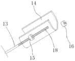
图7为发明的一种骨科膝关节术后功能锻炼装置的弧形小腿托板和连接杆连接结构示意图。Fig. 7 is a schematic diagram of the connection structure of the arc-shaped calf support plate and the connecting rod of an inventive orthopedic knee joint postoperative functional exercise device.
附图标记:1-支撑座;2-直线滑槽;3-第一缓冲组件;4-第二缓冲组件;5-第一电动推杆;6-第二电动推杆;7-第一铰接座;8-第二铰接座;9-第一缓冲弹簧;10-铰接块;11-第一铰接轴;12-脚踏板座;13-连接杆;14-弧形小腿托板;15-内通孔限位套;16-第一紧固螺帽;17-第三缓冲弹簧;18-第一外螺纹;19-支撑框架;20-背靠板;21-限位块;22-双头螺纹调节杆;23-第二铰接轴;24-支撑横柱;25-连接柱;26-支撑柱;27-限位卡齿;28-铰接耳座;29-第三铰接轴;30-支撑滑块;31-限位支撑板;32-限位导柱;33-第二外螺纹;34-限位通孔;35-第四缓冲弹簧;36-第二紧固螺帽;37-软性固定束带;38-第二缓冲弹簧。Reference signs: 1-support seat; 2-linear chute; 3-first buffer assembly; 4-second buffer assembly; 5-first electric push rod; 6-second electric push rod; 7-first hinge seat; 8- the second hinge seat; 9- the first buffer spring; 10- hinge block; 11- the first hinge shaft; 12- foot pedal seat; 13- connecting rod; 14- arc calf support plate; 15- Inner through hole limit sleeve; 16-first fastening nut; 17-third buffer spring; 18-first external thread; 19-support frame; 20-back plate; 21-limit block; 22-double head thread adjusting rod; 23-second hinge shaft; 24-support cross column; 25-connection column; 26-support column; 27-limiting tooth; 28- hinge ear seat; 29-third hinge shaft; Support slider; 31-limit support plate; 32-limit guide post; 33-second external thread; 34-limit through hole; 35-fourth buffer spring; 36-second fastening nut; 37- Soft fixing straps; 38-Second buffer spring.
具体实施方式Detailed ways
以下通过特定的具体实例说明本发明的实施方式,本领域技术人员可由本说明书所揭露的内容轻易地了解本发明的其他优点与功效。本发明还可以通过另外不同的具体实施方式加以实施或应用,本说明书中的各项细节也可以基于不同观点与应用,在没有背离本发明的精神下进行各种修饰或改变。需要说明的是,以下实施例中所提供的图示仅以示意方式说明本发明的基本构想,在不冲突的情况下,以下实施例及实施例中的特征可以相互组合。The embodiments of the present invention are described below through specific specific examples, and those skilled in the art can easily understand other advantages and effects of the present invention from the contents disclosed in this specification. The present invention can also be implemented or applied through other different specific embodiments, and various details in this specification can also be modified or changed based on different viewpoints and applications without departing from the spirit of the present invention. It should be noted that the drawings provided in the following embodiments are only used to illustrate the basic idea of the present invention in a schematic manner, and the following embodiments and features in the embodiments can be combined with each other without conflict.
其中,附图仅用于示例性说明,表示的仅是示意图,而非实物图,不能理解为对本发明的限制;为了更好地说明本发明的实施例,附图某些部件会有省略、放大或缩小,并不代表实际产品的尺寸;对本领域技术人员来说,附图中某些公知结构及其说明可能省略是可以理解的。Among them, the accompanying drawings are only used for exemplary description, and represent only schematic diagrams, not physical drawings, and should not be construed as limitations of the present invention; in order to better illustrate the embodiments of the present invention, some parts of the accompanying drawings will be omitted, The enlargement or reduction does not represent the size of the actual product; it is understandable to those skilled in the art that some well-known structures and their descriptions in the accompanying drawings may be omitted.
本发明实施例的附图中相同或相似的标号对应相同或相似的部件;在本发明的描述中,需要理解的是,若有术语“上”、“下”、“左”、“右”、“前”、“后”等指示的方位或位置关系为基于附图所示的方位或位置关系,仅是为了便于描述本发明和简化描述,而不是指示或暗示所指的装置或元件必须具有特定的方位、以特定的方位构造和操作,因此附图中描述位置关系的用语仅用于示例性说明,不能理解为对本发明的限制,对于本领域的普通技术人员而言,可以根据具体情况理解上述术语的具体含义。The same or similar numbers in the drawings of the embodiments of the present invention correspond to the same or similar components; in the description of the present invention, it should be understood that if there are terms “upper”, “lower”, “left” and “right” , "front", "rear" and other indicated orientations or positional relationships are based on the orientations or positional relationships shown in the accompanying drawings, and are only for the convenience of describing the present invention and simplifying the description, rather than indicating or implying that the indicated device or element must be It has a specific orientation, is constructed and operated in a specific orientation, so the terms describing the positional relationship in the accompanying drawings are only used for exemplary illustration, and should not be construed as a limitation of the present invention. situation to understand the specific meaning of the above terms.
如图1~7所述一种骨科膝关节术后功能锻炼装置,包括开设有直线滑槽2的支撑座1,直线滑槽2内滑动安装有端部通过第二缓冲弹簧38与支撑座1相抵的滑杆,滑杆上滑动安装有第一缓冲组件3和第二缓冲组件4,第一缓冲组件3和第二缓冲组件4上分别安装有第一电动推杆5和第二电动推杆6;第一电动推杆5的伸缩端固定有第一铰接座7;第一铰接座7上连接有第一缓冲弹簧9;第二电动推杆6的伸缩端固定有第二铰接座8;第二铰接座8上连接有铰接块10;第一缓冲弹簧9上方固定有脚踏板座12;铰接块10上方固定有弧形小腿托板14;脚踏板座12和弧形小腿托板14通过连接杆13连接。As shown in Figures 1 to 7, an orthopaedic knee joint postoperative functional exercise device includes a
连接杆13上设置有内通孔限位套15和第一紧固螺帽16;内通孔限位套15和第一紧固螺帽16之间设置第三缓冲弹簧17;第一缓冲组件3、第二缓冲组件4均包括支撑滑块30,支撑滑块30和限位支撑板31通过限位导柱32连接;限位导柱32上在限位支撑板31和支撑滑块30之间设置有第四缓冲弹簧35;限位支撑板31上设置有限位通孔34;限位导柱32上端穿过限位通孔34螺纹连接有第二紧固螺帽36。The connecting
支撑框架19通过第二铰接轴23连接有背靠板20;背靠板20上连接有支撑柱26;支撑框架19上设置有连接柱25;连接柱25上固定有支撑横柱24;支撑横柱24沿竖直方向设置有若干限位卡齿27;支撑柱26的另一端卡在支撑横柱24上。The
本实施例中,滑杆的两端分别设置有限位块21;对第一缓冲组件3和第二缓冲组件4进行限位。In this embodiment, the two ends of the sliding rod are respectively provided with limiting
本实施例中,第一铰接座7通过第一铰接轴11与第一缓冲弹簧9连接;第二铰接座8通过第一铰接轴11与铰接块10连接;使得第一铰接座7和第一缓冲弹簧9固定;使得第二铰接座8和铰接块10固定。In this embodiment, the
本实施例中,连接杆13上设置有第一外螺纹18;方便连接杆13分别与内通孔限位套15和第一紧固螺帽16螺纹连接。In this embodiment, the connecting
本实施例中,限位导柱32上设置有第二外螺纹33;方便限位导柱32与第二紧固螺帽36螺纹连接。In this embodiment, the limiting
本实施例中,背靠板20通过铰接耳座28和第三铰接轴29连接有支撑柱26;使得背靠板20与支撑柱26连接。In this embodiment, the
本实施例中,支撑横柱24沿竖直方向等距设置有十二个限位卡齿27;方便支撑柱26插入到不同位置,进而改变背靠板20的倾斜角度。In the present embodiment, the
本实施例中,支撑座1通过双头螺纹调节杆22连接有支撑框架19;所述支撑座1上设置有与双头螺纹调节杆22相适应的第一螺纹孔;支撑框架19上设置有与双头螺纹调节杆22相适应的第二螺纹孔;使得支撑座1与支撑框架19固定连接。In this embodiment, the
本实施例中,背靠板20的背面设置有铰接耳座28;背靠板20通过铰接耳座28与支撑柱26连接;使得背靠板20与支撑柱26固定。In this embodiment, the back of the
本实施例中,脚踏板座12与所述弧形小腿托板14上均设置有软性固定束带37。这样不管康复者是被动运动还是主动运动,软性固定束带37都能起到防止下肢在运动中从托板中脱落,造成受伤,起到稳定保护的作用。In this embodiment, the
该骨科膝关节术后功能锻炼装置工作时,首先患者躺在背靠板20上,使用支撑柱26通过卡在支撑横柱24上的十二个限位卡齿27的不同位置上;进而改变背靠板20的倾斜角度,然后根据患者的身高,搬移支撑座1或支撑框架19,改变支撑座1和支撑框架19的距离;使得患者能够把受伤的脚放置在脚踏板座12上,把小腿放置在弧形小腿托板14上,使用双头螺纹调节杆22把支撑座1和支撑框架19固定连接;然后保持第二电动推杆6不动;使用第一电动推杆5调整脚踏板座12的高度,进而改变脚踏板座12和弧形小腿托板14之间的角度,最终改变脚和小腿的弯曲度,进而使得膝关节得到屈伸训练,或者保持第一电动推杆5不动,使用第二电动推杆6调整弧形小腿托板14的高度,进而改变脚踏板座12和弧形小腿托板14之间的角度,最终改变脚和小腿的弯曲度,进而使得膝关节得到被动的屈伸训练。当患者需要主动运动时,第二电动推杆6和第一电动推杆5的高度调整好后,患者将受伤的脚放置在脚踏板座上,脚掌用力时,脚掌下方的第一缓冲弹簧9恢复形变,对脚掌施加一个反方向的力,有助于脚踝的锻炼,与此同时,支撑座1上滑槽内滑杆沿着直线滑槽前后移动,滑杆两端的第二缓冲弹簧38也逐渐恢复形变,对患者的膝关节施加一个反方向的力,有助于膝关节的康复。When the orthopaedic knee joint postoperative functional exercise device works, first the patient lies on the
该骨科膝关节术后功能锻炼装置,支撑座1通过双头螺纹调节杆22连接有支撑框架19;支撑座1通过直线滑槽2连接有第一缓冲组件3和第二缓冲组件4;铰接块10固定有弧形小腿托板14;脚踏板座12和弧形小腿托板14通过连接杆13连接;连接杆13上设置有内通孔限位套15和第一紧固螺帽16;根据调整支撑座1和支撑框架19之间的距离,适应不同身高的患者躺在背靠板20上,使得患者能够把受伤的脚放置在脚踏板座12上,把小腿放置在弧形小腿托板14上,根据调整第一缓冲组件3和第二缓冲组件4,脚踏板座12和弧形小腿托板14之间的距离,使得适应不同长度的小腿进行屈伸训练,通用性强,能够根据患者的不同的受伤程度,慢慢调整第二电动推杆6或第一电动推杆5的高度,进而使得根据患者的承受能力合理的设定锻炼,避免患者因为难以忍受的疼痛而采取不配合态度,从而不能达到良好的恢复效果。In this orthopaedic knee joint postoperative functional exercise device, the
该骨科膝关节术后功能锻炼装置,第一缓冲组件3、第二缓冲组件4均包括支撑滑块30、限位支撑板31、限位导柱32、第二外螺纹33、限位通孔34、第四缓冲弹簧35和第二紧固螺帽36;支撑滑块30和限位支撑板31通过限位导柱32连接;限位导柱32上在限位支撑板31和支撑滑块30之间设置有第四缓冲弹簧35;通过设置有限位支撑板31上设置有限位通孔34;限位导柱32上端穿过限位通孔34螺纹连接有第二紧固螺帽36;通过松紧第二紧固螺帽36,使得限位支撑板31沿着限位导柱32的方向往下移动,使得第四缓冲弹簧35被压缩,进而使得缓冲效果好,脚踏板座12和弧形小腿托板14通过连接杆13连接;连接杆13上设置有内通孔限位套15和第一紧固螺帽16;内通孔限位套15和第一紧固螺帽16之间设置有第三缓冲弹簧17;松紧第一紧固螺帽16,改变内通孔限位套15和第一紧固螺帽16之间的距离,使得第三缓冲弹簧17被压缩,使得该装置缓冲效果好。In the orthopaedic knee joint postoperative functional exercise device, the
该骨科膝关节术后功能锻炼装置,支撑座1通过双头螺纹调节杆22连接有支撑框架19;支撑框架19通过第二铰接轴23连接有背靠板20;背靠板20的背面设置有铰接耳座28;铰接耳座28连接有支撑柱26;支撑框架19上设置有连接柱25;连接柱25上固定有支撑横柱24;支撑横柱24沿竖直方向设置有若干限位卡齿27;支撑柱26的另一端卡在支撑横柱24上,通过设置有支撑框架19、背靠板20、第二铰接轴23、连接柱25、支撑柱26和限位卡齿27,用支撑柱26通过卡在支撑横柱24上的十二个限位卡齿27的不同位置上;进而改变背靠板20的倾斜角度,使得患者躺着舒服。In this orthopaedic knee joint postoperative functional exercise device, the
最后说明的是,以上实施例仅用以说明本发明的技术方案而非限制,尽管参照较佳实施例对本发明进行了详细说明,本领域的普通技术人员应当理解,可以对本发明的技术方案进行修改或者等同替换,而不脱离本技术方案的宗旨和范围,其均应涵盖在本发明的权利要求范围当中。Finally, it should be noted that the above embodiments are only used to illustrate the technical solutions of the present invention and not to limit them. Although the present invention has been described in detail with reference to the preferred embodiments, those of ordinary skill in the art should understand that the technical solutions of the present invention can be Modifications or equivalent replacements, without departing from the spirit and scope of the technical solution, should all be included in the scope of the claims of the present invention.
Claims (9)
Translated fromChinesePriority Applications (1)
| Application Number | Priority Date | Filing Date | Title |
|---|---|---|---|
| CN201911185708.8ACN110833497B (en) | 2019-11-27 | 2019-11-27 | An orthopedic knee joint postoperative functional exercise device |
Applications Claiming Priority (1)
| Application Number | Priority Date | Filing Date | Title |
|---|---|---|---|
| CN201911185708.8ACN110833497B (en) | 2019-11-27 | 2019-11-27 | An orthopedic knee joint postoperative functional exercise device |
Publications (2)
| Publication Number | Publication Date |
|---|---|
| CN110833497Atrue CN110833497A (en) | 2020-02-25 |
| CN110833497B CN110833497B (en) | 2022-03-11 |
Family
ID=69577664
Family Applications (1)
| Application Number | Title | Priority Date | Filing Date |
|---|---|---|---|
| CN201911185708.8AExpired - Fee RelatedCN110833497B (en) | 2019-11-27 | 2019-11-27 | An orthopedic knee joint postoperative functional exercise device |
Country Status (1)
| Country | Link |
|---|---|
| CN (1) | CN110833497B (en) |
Cited By (14)
| Publication number | Priority date | Publication date | Assignee | Title |
|---|---|---|---|---|
| CN111569367A (en)* | 2020-05-22 | 2020-08-25 | 吕新华 | Recovered telecontrol equipment of orthopedics patient shank |
| CN111839994A (en)* | 2020-07-08 | 2020-10-30 | 海宁世正贸易有限公司 | An exercise device for postoperative knee joint |
| CN111973401A (en)* | 2020-09-03 | 2020-11-24 | 温州市中西医结合医院 | Ankle joint wound rehabilitation device |
| CN112603765A (en)* | 2020-12-31 | 2021-04-06 | 固安博健生物技术有限公司 | Leg exercise auxiliary instrument based on biomechanics |
| CN112618251A (en)* | 2020-11-30 | 2021-04-09 | 中国人民解放军陆军军医大学第一附属医院 | Rehabilitation training device for muscle injury of lower limbs |
| CN112656644A (en)* | 2020-12-21 | 2021-04-16 | 中国人民解放军陆军军医大学第一附属医院 | Cerebral apoplexy patient rehabilitation training device |
| CN113244087A (en)* | 2021-04-30 | 2021-08-13 | 南通市第一人民医院 | Old patient's shank trainer |
| CN113317965A (en)* | 2021-06-18 | 2021-08-31 | 中国人民解放军陆军军医大学第一附属医院 | Hip and knee bending angle adjusting device and method |
| CN113730877A (en)* | 2021-09-16 | 2021-12-03 | 常州市中医医院 | Orthopedic leg rehabilitation auxiliary exercise equipment and exercise method thereof |
| CN113813142A (en)* | 2021-10-21 | 2021-12-21 | 郑州安杰莱智能科技有限公司 | An ankle rehabilitation robot |
| CN114247091A (en)* | 2021-12-22 | 2022-03-29 | 濮阳市人民医院 | Recovered device and protective apparatus of taking exercise of joint surgery postoperative limbs |
| CN114425141A (en)* | 2022-01-13 | 2022-05-03 | 陈健 | Old person's low limbs postoperative rehabilitation training device |
| CN115089927A (en)* | 2022-06-16 | 2022-09-23 | 江苏医药职业学院 | A knee joint rehabilitation training device |
| CN115670863A (en)* | 2022-11-03 | 2023-02-03 | 浙江大学 | Orthopedics joint postoperative training ware |
Citations (25)
| Publication number | Priority date | Publication date | Assignee | Title |
|---|---|---|---|---|
| DE3939987A1 (en)* | 1989-12-02 | 1991-06-06 | Schmidt Hoensdorf Fritjof Dr M | Physiotherapy appts. for treating patient's leg - has slide which is pushed against pneumatic resistance |
| JP2004081576A (en)* | 2002-08-27 | 2004-03-18 | Yaskawa Electric Corp | Rehabilitation support device |
| CN201389292Y (en)* | 2009-04-14 | 2010-01-27 | 陈鸿强 | Training aids for recovering vein function of lower limbs |
| CN202506049U (en)* | 2012-04-06 | 2012-10-31 | 战军华 | Lower limb rehabilitation training bed |
| CN203089785U (en)* | 2013-02-25 | 2013-07-31 | 中国计量学院 | Leg muscle exercising device based on pneumatic muscles |
| CN204092519U (en)* | 2014-08-05 | 2015-01-14 | 毕光辉 | Cerebral thrombosis device for healing and training |
| CN105125381A (en)* | 2015-10-19 | 2015-12-09 | 吉林大学 | Multi-degree-of-freedom adjustable ankle and knee joint linkage rehabilitative training machine |
| CN205094938U (en)* | 2015-10-19 | 2016-03-23 | 吉林大学 | Ankle and knee joint linkage rehabilitation training device with adjustable multi freedom |
| CN206228580U (en)* | 2016-08-25 | 2017-06-09 | 杨瑞鑫 | A kind of neurosurgical care massage machine |
| CN206315411U (en)* | 2016-12-28 | 2017-07-11 | 吉林大学 | A kind of stretching type leg training convalescence device |
| CN206508469U (en)* | 2017-02-20 | 2017-09-22 | 嵊州领航信息科技有限公司 | A kind of device for rehabilitation |
| CN107281703A (en)* | 2017-08-08 | 2017-10-24 | 岳明 | A kind of foot-operated lower limb body position rehabilitation assistor |
| CN206745588U (en)* | 2016-12-15 | 2017-12-15 | 上海理工大学 | Towed ankle joint rehabilitation training device |
| CN108095975A (en)* | 2018-01-29 | 2018-06-01 | 安阳市翔宇医疗设备有限责任公司 | Combined type ankle-joint training device |
| CN108309694A (en)* | 2018-03-02 | 2018-07-24 | 哈工大机器人(合肥)国际创新研究院 | A kind of foot drive-type lower limb rehabilitation training device |
| CN207785792U (en)* | 2018-01-29 | 2018-08-31 | 苏美开 | A kind of lower limb rehabilitation training device |
| CN108743241A (en)* | 2018-07-12 | 2018-11-06 | 郑州大学第附属医院 | Lower limb synthetic therapy equipment and its application method |
| CN208229106U (en)* | 2017-05-26 | 2018-12-14 | 鹤壁市人民医院 | A kind of postoperative massage machine in medical leg |
| CN208319505U (en)* | 2017-08-01 | 2019-01-04 | 广东技术师范学院 | A kind of adjustable type lower limb recovering aid instrument |
| CN109199796A (en)* | 2018-10-29 | 2019-01-15 | 西安交通大学医学院第附属医院 | A kind of pneumatic electromagnetic levitation type recovery set for lower limbs |
| CN208388947U (en)* | 2017-08-01 | 2019-01-18 | 广东技术师范学院 | A kind of lower limb recovering aid instrument of good buffer effect |
| CN208626129U (en)* | 2017-08-15 | 2019-03-22 | 无锡市第五人民医院 | A kind of Neurology lower limb exercise convalescence device |
| CN109646251A (en)* | 2019-02-22 | 2019-04-19 | 四川省人民医院 | It is a kind of for the movable device of ICU patient legs |
| CN110151496A (en)* | 2019-07-02 | 2019-08-23 | 安徽工业大学 | A multi-position lower limb rehabilitation robot and its application method |
| CN209575618U (en)* | 2019-02-19 | 2019-11-05 | 江西工业贸易职业技术学院 | A kind of multifunction sport body-building device |
- 2019
- 2019-11-27CNCN201911185708.8Apatent/CN110833497B/ennot_activeExpired - Fee Related
Patent Citations (25)
| Publication number | Priority date | Publication date | Assignee | Title |
|---|---|---|---|---|
| DE3939987A1 (en)* | 1989-12-02 | 1991-06-06 | Schmidt Hoensdorf Fritjof Dr M | Physiotherapy appts. for treating patient's leg - has slide which is pushed against pneumatic resistance |
| JP2004081576A (en)* | 2002-08-27 | 2004-03-18 | Yaskawa Electric Corp | Rehabilitation support device |
| CN201389292Y (en)* | 2009-04-14 | 2010-01-27 | 陈鸿强 | Training aids for recovering vein function of lower limbs |
| CN202506049U (en)* | 2012-04-06 | 2012-10-31 | 战军华 | Lower limb rehabilitation training bed |
| CN203089785U (en)* | 2013-02-25 | 2013-07-31 | 中国计量学院 | Leg muscle exercising device based on pneumatic muscles |
| CN204092519U (en)* | 2014-08-05 | 2015-01-14 | 毕光辉 | Cerebral thrombosis device for healing and training |
| CN105125381A (en)* | 2015-10-19 | 2015-12-09 | 吉林大学 | Multi-degree-of-freedom adjustable ankle and knee joint linkage rehabilitative training machine |
| CN205094938U (en)* | 2015-10-19 | 2016-03-23 | 吉林大学 | Ankle and knee joint linkage rehabilitation training device with adjustable multi freedom |
| CN206228580U (en)* | 2016-08-25 | 2017-06-09 | 杨瑞鑫 | A kind of neurosurgical care massage machine |
| CN206745588U (en)* | 2016-12-15 | 2017-12-15 | 上海理工大学 | Towed ankle joint rehabilitation training device |
| CN206315411U (en)* | 2016-12-28 | 2017-07-11 | 吉林大学 | A kind of stretching type leg training convalescence device |
| CN206508469U (en)* | 2017-02-20 | 2017-09-22 | 嵊州领航信息科技有限公司 | A kind of device for rehabilitation |
| CN208229106U (en)* | 2017-05-26 | 2018-12-14 | 鹤壁市人民医院 | A kind of postoperative massage machine in medical leg |
| CN208388947U (en)* | 2017-08-01 | 2019-01-18 | 广东技术师范学院 | A kind of lower limb recovering aid instrument of good buffer effect |
| CN208319505U (en)* | 2017-08-01 | 2019-01-04 | 广东技术师范学院 | A kind of adjustable type lower limb recovering aid instrument |
| CN107281703A (en)* | 2017-08-08 | 2017-10-24 | 岳明 | A kind of foot-operated lower limb body position rehabilitation assistor |
| CN208626129U (en)* | 2017-08-15 | 2019-03-22 | 无锡市第五人民医院 | A kind of Neurology lower limb exercise convalescence device |
| CN108095975A (en)* | 2018-01-29 | 2018-06-01 | 安阳市翔宇医疗设备有限责任公司 | Combined type ankle-joint training device |
| CN207785792U (en)* | 2018-01-29 | 2018-08-31 | 苏美开 | A kind of lower limb rehabilitation training device |
| CN108309694A (en)* | 2018-03-02 | 2018-07-24 | 哈工大机器人(合肥)国际创新研究院 | A kind of foot drive-type lower limb rehabilitation training device |
| CN108743241A (en)* | 2018-07-12 | 2018-11-06 | 郑州大学第附属医院 | Lower limb synthetic therapy equipment and its application method |
| CN109199796A (en)* | 2018-10-29 | 2019-01-15 | 西安交通大学医学院第附属医院 | A kind of pneumatic electromagnetic levitation type recovery set for lower limbs |
| CN209575618U (en)* | 2019-02-19 | 2019-11-05 | 江西工业贸易职业技术学院 | A kind of multifunction sport body-building device |
| CN109646251A (en)* | 2019-02-22 | 2019-04-19 | 四川省人民医院 | It is a kind of for the movable device of ICU patient legs |
| CN110151496A (en)* | 2019-07-02 | 2019-08-23 | 安徽工业大学 | A multi-position lower limb rehabilitation robot and its application method |
Cited By (19)
| Publication number | Priority date | Publication date | Assignee | Title |
|---|---|---|---|---|
| CN111569367A (en)* | 2020-05-22 | 2020-08-25 | 吕新华 | Recovered telecontrol equipment of orthopedics patient shank |
| CN111839994A (en)* | 2020-07-08 | 2020-10-30 | 海宁世正贸易有限公司 | An exercise device for postoperative knee joint |
| CN111839994B (en)* | 2020-07-08 | 2024-02-20 | 海宁世正贸易有限公司 | An exercise device for postoperative knee joints |
| CN111973401A (en)* | 2020-09-03 | 2020-11-24 | 温州市中西医结合医院 | Ankle joint wound rehabilitation device |
| CN112618251A (en)* | 2020-11-30 | 2021-04-09 | 中国人民解放军陆军军医大学第一附属医院 | Rehabilitation training device for muscle injury of lower limbs |
| CN112656644A (en)* | 2020-12-21 | 2021-04-16 | 中国人民解放军陆军军医大学第一附属医院 | Cerebral apoplexy patient rehabilitation training device |
| CN112656644B (en)* | 2020-12-21 | 2022-06-24 | 中国人民解放军陆军军医大学第一附属医院 | Cerebral apoplexy patient rehabilitation training device |
| CN112603765A (en)* | 2020-12-31 | 2021-04-06 | 固安博健生物技术有限公司 | Leg exercise auxiliary instrument based on biomechanics |
| CN112603765B (en)* | 2020-12-31 | 2024-08-23 | 固安博健生物技术有限公司 | Leg exercise auxiliary instrument based on biomechanics |
| CN113244087B (en)* | 2021-04-30 | 2022-05-20 | 南通市第一人民医院 | Old patient's shank trainer |
| CN113244087A (en)* | 2021-04-30 | 2021-08-13 | 南通市第一人民医院 | Old patient's shank trainer |
| CN113317965A (en)* | 2021-06-18 | 2021-08-31 | 中国人民解放军陆军军医大学第一附属医院 | Hip and knee bending angle adjusting device and method |
| CN113730877A (en)* | 2021-09-16 | 2021-12-03 | 常州市中医医院 | Orthopedic leg rehabilitation auxiliary exercise equipment and exercise method thereof |
| CN113813142A (en)* | 2021-10-21 | 2021-12-21 | 郑州安杰莱智能科技有限公司 | An ankle rehabilitation robot |
| CN114247091A (en)* | 2021-12-22 | 2022-03-29 | 濮阳市人民医院 | Recovered device and protective apparatus of taking exercise of joint surgery postoperative limbs |
| CN114425141A (en)* | 2022-01-13 | 2022-05-03 | 陈健 | Old person's low limbs postoperative rehabilitation training device |
| CN114425141B (en)* | 2022-01-13 | 2022-12-06 | 陈健 | Lower limb postoperative rehabilitation training device for old people |
| CN115089927A (en)* | 2022-06-16 | 2022-09-23 | 江苏医药职业学院 | A knee joint rehabilitation training device |
| CN115670863A (en)* | 2022-11-03 | 2023-02-03 | 浙江大学 | Orthopedics joint postoperative training ware |
Also Published As
| Publication number | Publication date |
|---|---|
| CN110833497B (en) | 2022-03-11 |
Similar Documents
| Publication | Publication Date | Title |
|---|---|---|
| CN110833497A (en) | Orthopedic knee joint postoperative function exercise device | |
| KR100942968B1 (en) | A movement machine for rehabilitation medical cure | |
| US5100131A (en) | Back muscle exercising and stretching apparatus | |
| US10226374B2 (en) | Cervical brace | |
| US11246788B2 (en) | Spine regularity rotation motion device | |
| WO2019183293A1 (en) | Adaptive ergonomic positioning device | |
| CN109009616A (en) | A kind of cervical vertebra actively corrects exercise treatment device | |
| WO2018117897A1 (en) | Multi-functional therapeutic hospital bed convertible into a standing aid | |
| CN107951677A (en) | A kind of knee-joint rehabilitation training device | |
| CN214968409U (en) | Beach chair surgical bed for shoulder surgery | |
| CN111643241A (en) | Knee joint orthosis assisting in stretching and bending knee | |
| CN110882132A (en) | Rehabilitation training device for ankles | |
| CN211705772U (en) | Recovered device of taking exercise of orthopedics | |
| CN113730175A (en) | Flexible cross traction rehabilitation bed | |
| CN209033001U (en) | A kind of fixed nursing device for orthopedics | |
| CN204839850U (en) | Support frame with adjustable drop foot is used for preventing | |
| CN213076422U (en) | Flexible cross traction rehabilitation bed | |
| US20210338513A1 (en) | Spine regularity rotation motion device | |
| CN112704844A (en) | Rehabilitation training device for stiffness of knee joint | |
| CN218220962U (en) | Postoperative rehabilitation training device | |
| CN212326877U (en) | A disc motor exoskeleton for rehabilitation training | |
| CN213192338U (en) | Rehabilitation training device for stiffness of knee joint | |
| CN210355851U (en) | An orthopedic lower limb rehabilitation nursing device | |
| AU2015202914B2 (en) | Cervical Brace | |
| CN220695404U (en) | Reset fixing orthopedic device for orthopedics department |
Legal Events
| Date | Code | Title | Description |
|---|---|---|---|
| PB01 | Publication | ||
| PB01 | Publication | ||
| SE01 | Entry into force of request for substantive examination | ||
| SE01 | Entry into force of request for substantive examination | ||
| GR01 | Patent grant | ||
| GR01 | Patent grant | ||
| CF01 | Termination of patent right due to non-payment of annual fee | ||
| CF01 | Termination of patent right due to non-payment of annual fee | Granted publication date:20220311 |