CN110832246A - light source for lamps - Google Patents
light source for lampsDownload PDFInfo
- Publication number
- CN110832246A CN110832246ACN201880031438.2ACN201880031438ACN110832246ACN 110832246 ACN110832246 ACN 110832246ACN 201880031438 ACN201880031438 ACN 201880031438ACN 110832246 ACN110832246 ACN 110832246A
- Authority
- CN
- China
- Prior art keywords
- light source
- light
- luminaire
- optical element
- leds
- Prior art date
- Legal status (The legal status is an assumption and is not a legal conclusion. Google has not performed a legal analysis and makes no representation as to the accuracy of the status listed.)
- Pending
Links
Images


Classifications
- F—MECHANICAL ENGINEERING; LIGHTING; HEATING; WEAPONS; BLASTING
- F21—LIGHTING
- F21K—NON-ELECTRIC LIGHT SOURCES USING LUMINESCENCE; LIGHT SOURCES USING ELECTROCHEMILUMINESCENCE; LIGHT SOURCES USING CHARGES OF COMBUSTIBLE MATERIAL; LIGHT SOURCES USING SEMICONDUCTOR DEVICES AS LIGHT-GENERATING ELEMENTS; LIGHT SOURCES NOT OTHERWISE PROVIDED FOR
- F21K9/00—Light sources using semiconductor devices as light-generating elements, e.g. using light-emitting diodes [LED] or lasers
- F21K9/60—Optical arrangements integrated in the light source, e.g. for improving the colour rendering index or the light extraction
- F21K9/65—Optical arrangements integrated in the light source, e.g. for improving the colour rendering index or the light extraction specially adapted for changing the characteristics or the distribution of the light, e.g. by adjustment of parts
- F—MECHANICAL ENGINEERING; LIGHTING; HEATING; WEAPONS; BLASTING
- F21—LIGHTING
- F21V—FUNCTIONAL FEATURES OR DETAILS OF LIGHTING DEVICES OR SYSTEMS THEREOF; STRUCTURAL COMBINATIONS OF LIGHTING DEVICES WITH OTHER ARTICLES, NOT OTHERWISE PROVIDED FOR
- F21V3/00—Globes; Bowls; Cover glasses
- F—MECHANICAL ENGINEERING; LIGHTING; HEATING; WEAPONS; BLASTING
- F21—LIGHTING
- F21S—NON-PORTABLE LIGHTING DEVICES; SYSTEMS THEREOF; VEHICLE LIGHTING DEVICES SPECIALLY ADAPTED FOR VEHICLE EXTERIORS
- F21S10/00—Lighting devices or systems producing a varying lighting effect
- F21S10/06—Lighting devices or systems producing a varying lighting effect flashing, e.g. with rotating reflector or light source
- F—MECHANICAL ENGINEERING; LIGHTING; HEATING; WEAPONS; BLASTING
- F21—LIGHTING
- F21V—FUNCTIONAL FEATURES OR DETAILS OF LIGHTING DEVICES OR SYSTEMS THEREOF; STRUCTURAL COMBINATIONS OF LIGHTING DEVICES WITH OTHER ARTICLES, NOT OTHERWISE PROVIDED FOR
- F21V13/00—Producing particular characteristics or distribution of the light emitted by means of a combination of elements specified in two or more of main groups F21V1/00 - F21V11/00
- F21V13/02—Combinations of only two kinds of elements
- F21V13/04—Combinations of only two kinds of elements the elements being reflectors and refractors
- F21V13/06—Combinations of only two kinds of elements the elements being reflectors and refractors a reflector being rotatable
- F—MECHANICAL ENGINEERING; LIGHTING; HEATING; WEAPONS; BLASTING
- F21—LIGHTING
- F21V—FUNCTIONAL FEATURES OR DETAILS OF LIGHTING DEVICES OR SYSTEMS THEREOF; STRUCTURAL COMBINATIONS OF LIGHTING DEVICES WITH OTHER ARTICLES, NOT OTHERWISE PROVIDED FOR
- F21V14/00—Controlling the distribution of the light emitted by adjustment of elements
- F21V14/04—Controlling the distribution of the light emitted by adjustment of elements by movement of reflectors
- F—MECHANICAL ENGINEERING; LIGHTING; HEATING; WEAPONS; BLASTING
- F21—LIGHTING
- F21V—FUNCTIONAL FEATURES OR DETAILS OF LIGHTING DEVICES OR SYSTEMS THEREOF; STRUCTURAL COMBINATIONS OF LIGHTING DEVICES WITH OTHER ARTICLES, NOT OTHERWISE PROVIDED FOR
- F21V14/00—Controlling the distribution of the light emitted by adjustment of elements
- F21V14/06—Controlling the distribution of the light emitted by adjustment of elements by movement of refractors
- F—MECHANICAL ENGINEERING; LIGHTING; HEATING; WEAPONS; BLASTING
- F21—LIGHTING
- F21Y—INDEXING SCHEME ASSOCIATED WITH SUBCLASSES F21K, F21L, F21S and F21V, RELATING TO THE FORM OR THE KIND OF THE LIGHT SOURCES OR OF THE COLOUR OF THE LIGHT EMITTED
- F21Y2115/00—Light-generating elements of semiconductor light sources
- F21Y2115/10—Light-emitting diodes [LED]
Landscapes
- Engineering & Computer Science (AREA)
- General Engineering & Computer Science (AREA)
- Physics & Mathematics (AREA)
- Microelectronics & Electronic Packaging (AREA)
- Optics & Photonics (AREA)
- Non-Portable Lighting Devices Or Systems Thereof (AREA)
- Resistance Heating (AREA)
Abstract
Description
Translated fromChinese技术领域technical field
本发明涉及一种用于灯具的光源。The present invention relates to a light source for lamps.
背景技术Background technique
在本说明书中,使用以下术语:“光源”是指实际的光发射器,以及用于控制光的传播的紧密关联的组件;“灯具”是指包括光源在内的完整的光单元。In this specification, the following terms are used: "light source" refers to the actual light emitter, and closely related components used to control the propagation of light; "luminaire" refers to the complete light unit including the light source.
在模拟传统照明设备的情况下,“灯饰”是“灯具”的替代术语。"Fixture" is an alternate term for "lamp" in the context of simulating traditional lighting fixtures.
根据上述含义的光源的一个示例是远光/近光头灯灯泡,其具有位于玻璃元件中的两个元件,并具有一个灯罩,以限制从近光元件发出的光,以不致目眩,而包括灯泡/光源在内的整个头灯单元是一个灯具。An example of a light source according to the above meaning is a high beam/low beam headlight bulb, which has two elements in a glass element and a lampshade to limit the light emitted from the low beam element so as not to be dazzling, but includes a bulb The entire headlight unit including the light source is a light fixture.
街道照明灯具中使用的LED光源往往会在灯具下方产生光亮处,而在光亮处之间的照明减少。LED light sources used in street lighting fixtures tend to produce bright spots below the luminaire with reduced illumination between the bright spots.
发明内容SUMMARY OF THE INVENTION
本发明的目的是提供一种改进的照明光源。It is an object of the present invention to provide an improved lighting source.
在我们的申请第1707673.8号(我们的较早申请)中,我们描述了我们发明的用于灯具或灯饰的光源。根据这一发明,提供了一种用于灯具或灯饰的光源,该光源包括:In our application No. 1707673.8 (our earlier application) we describe our invention of a light source for a lamp or lighting fixture. According to this invention, there is provided a light source for a lamp or lighting, the light source comprising:
·至少一个发光二极管(LED),at least one light emitting diode (LED),
·罩结构,利用该罩机构,LED固定在罩结构内,罩结构Cover structure, with this cover mechanism, the LED is fixed in the cover structure, the cover structure
·为透明的或至少半透明的,并且be transparent or at least translucent, and
·被布置用以拦截并重新分配来自LED的光,以及be arranged to intercept and redistribute light from the LEDs, and
·位于罩结构中的光学元件,用于将来自LED的光偏离不需要照明或至少需要减小强度的照明的方向。• An optical element in the housing structure to divert the light from the LEDs in a direction that does not require illumination, or at least requires reduced intensity illumination.
现在我们已经研制出了具有角度上可调节的光学元件的特征的发明,其方便地与罩一起。虽然优选地是,光学元件是反光器,但是可以设想的是,可以提供其它光学元件,例如棱镜装置或者实际上是遮光罩。We have now developed an invention featuring an angularly adjustable optical element, conveniently together with a cover. Although preferably the optical element is a reflector, it is envisaged that other optical elements may be provided, such as prismatic arrangements or indeed light shields.
确实,在我们的早期申请中,我们公开了一种将光学元件/反光器固定在罩内的中心螺钉,并且表明其可以定位成将光远离房屋反射。Indeed, in our earlier application we disclosed a central screw that secures the optic/reflector within the housing and showed that it could be positioned to reflect light away from the house.
我们在下面描述的角度上可调节的实施例具有罩的角度调节效果,在罩中有反光器。但是,可以省去罩,并且仅对反光器提供角度上可调节的支撑件。The angularly adjustable embodiments we describe below have the angular adjustment effect of the hood with the reflector in it. However, it is possible to omit the cover and provide only the angularly adjustable support for the reflector.
光学元件可以被构造用以减小一个方向上的光强度,将光大致分散在其它方向上,或者可以被构造用以将光集中在一个或多个特定方向上。通常,这些方向将围绕至少基本竖直的轴线,并且LED朝下指向或至少布置在LED的PCB下方。然而,反光器或其它光学装置可以布置用以在另一平面中起作用,以使发射出来的光的强度随着与水平面所成的角度而变化,特定目的是避免使接近灯具或灯饰的人(通常是行人)目眩并且/或者避免光在灯具或灯饰下方“集中(pooling)”。Optical elements may be configured to reduce light intensity in one direction, generally disperse light in other directions, or may be configured to concentrate light in one or more specific directions. Typically, these directions will be around an at least substantially vertical axis, with the LEDs pointing downwards or at least arranged below the PCB of the LEDs. However, a reflector or other optical device may be arranged to function in another plane such that the intensity of the emitted light varies with the angle to the horizontal, with the specific purpose of avoiding distracting persons approaching the luminaire or lighting fixture Dazzle (often pedestrians) and/or avoid "pooling" of light under a light fixture or lighting fixture.
虽然针对每个光源可以提供多于一个的反光器或光学元件,其中光将沿两个大致方向(如沿着两条或更多条道路)投射,但是这也可以通过针对每个灯具提供多个光源而以更大的灵活性实现。While more than one reflector or optical element can be provided for each light source, where the light will be projected in two general directions (eg, along two or more roads), this can also be achieved by providing more than one reflector or optical element per luminaire. A light source can be realized with greater flexibility.
可以设想两个或可能的是更多的反光器或光学元件可以具有分别不同的功能。例如,可以在LED下方提供反光器或元件,以分散向下发射出来的侧向光,否则侧向光将产生目眩并且/或者集中;而另一反光器或元件可以设置于LED的一侧,以将光聚集在某些特定方向上。应当注意,这种集中在从LED发出的光的大致方向的侧向上。换句话说,在光源处于所设想的使用定向的情况下,发射方向通常是向下的,而反射方向通常是侧向的。It is envisaged that two or possibly more reflectors or optical elements may have respectively different functions. For example, a reflector or element could be provided below the LED to disperse downwardly emitted side light that would otherwise be dazzled and/or concentrated; while another reflector or element could be placed on one side of the LED, to focus light in certain directions. It should be noted that this concentration is lateral to the general direction of light emitted from the LEDs. In other words, with the light source in the envisaged orientation of use, the emission direction is generally downwards and the reflection direction is generally lateral.
例如,在LED下方的反光器可以是尖头状的,以将光向侧面引导。LED的一侧的反光器可以类似地是呈尖头状的,以沿两个相反的方向而不是横向于那些方向引导光。可以在LED的相对侧上提供两个这样的反光器。还可以设想,可以类似地设置更多这样的反射器,以照明四个方向中的三个方向。For example, the reflectors below the LEDs can be pointed to direct the light sideways. The reflector on one side of the LED may similarly be pointed to direct light in two opposite directions rather than transverse to those directions. Two such reflectors can be provided on opposite sides of the LED. It is also envisaged that more such reflectors could be similarly provided to illuminate three of the four directions.
进一步设想,用于引导侧向光的光学元件可以至少是大致抛物线形的,以在单个方向上引导光,而用于另一方向的光则来自第二光源LED和反光器。It is further envisaged that the optical element for directing side light may be at least substantially parabolic to direct light in a single direction, while light for the other direction comes from the second light source LED and reflector.
方便地是,能够将角度上可调节的支撑件(在设置有罩的情况下,与罩一起)可调节地布置在用于该角度上可调节的支撑件的散热器或基座上,在该散热器上或基座上承载LED和/或其PCB。Conveniently, the angularly adjustable support (together with the hood, if provided) can be adjustably arranged on the heat sink or base for the angularly adjustable support, where The LEDs and/or their PCBs are carried on the heat sink or on the base.
在提供两个光源的情况下,它们可以利用共同的散热器。然而,在优选实施例中,为光源设置了相应的散热器。Where two light sources are provided, they can utilize a common heat sink. However, in a preferred embodiment, a corresponding heat sink is provided for the light source.
在优选实施例中,支撑件被夹在散热器基座上,并设有装有弹簧的棘爪,用于保持调节结果,并且基座具有一组圆形布置的凹部,棘爪与所述凹部接合。In a preferred embodiment, the support is clamped to the radiator base and is provided with spring-loaded pawls for holding the adjustment, and the base has a set of circularly arranged recesses, the pawls being in contact with the said The recess engages.
为避免疑问,以下来自我们的较早申请的斜体形式的详细信息适用于本发明的发展。For the avoidance of doubt, the following details in italics from our earlier application apply to the development of the present invention.
正常情况下,罩结构将在使用中安装成从支撑件向下延伸。但是,它可能会从支撑件向上延伸。两种布置都用于带有罩的气体照明中,本发明的罩结构试图对所述罩进行模仿。Normally, the hood structure will be mounted to extend downwardly from the support in use. However, it may extend upward from the support. Both arrangements are used in gas lighting with a hood, which the hood structure of the present invention seeks to emulate.
LED通常将在二极管上包括荧光涂层,以用于控制二极管光的颜色。它还可以包括将光聚焦在特定方向上的透镜。本发明适用于这些LED和其它LED结构。LEDs will typically include a fluorescent coating on the diode for controlling the color of the diode light. It can also include lenses that focus light in a specific direction. The present invention is applicable to these LEDs and other LED structures.
光学元件/反光器可以布置在罩结构的底部处,以向下传播光,从而减小当罩结构在顶部安装且LED位于在其顶部时紧挨在光源下方的照明强度。Optical elements/reflectors can be arranged at the bottom of the cover structure to propagate the light downwards, reducing the illumination intensity immediately below the light source when the cover structure is mounted on top and the LEDs are located on top of it.
附加地是或替代地是,该反光器或另一反光器可以被布置于罩结构的一侧,以减少侧向或其它方向的照明,如减少进入将灯具安装在路灯中所在的房屋中的照明。Additionally or alternatively, the reflector or another reflector may be arranged on one side of the hood structure to reduce lateral or other directional lighting, such as reducing entry into the house where the luminaire is installed in the street light. illumination.
通常,罩结构将具有大致抛物面形状,其中术语“罩”是从煤气灯的罩衍生而来的,并且本发明的罩结构被成形为能够在某些应用中模仿煤气灯的罩。Typically, the hood structure will have a generally parabolic shape, where the term "hood" is derived from the hood of a gas lamp, and the hood structure of the present invention is shaped to mimic the hood of a gas lamp in certain applications.
罩结构可以是玻璃的,优选是磨砂的,以提供光的重新分配。在优选的实施例中,罩结构是聚合物材料的。优选地是,它具有多个孔,以帮助进一步的重新分配。方便地是,通过所谓的3D打印来生产罩结构。The cover structure may be glass, preferably frosted, to provide light redistribution. In a preferred embodiment, the cover structure is of a polymeric material. Preferably, it has multiple holes to aid further redistribution. Conveniently, the hood structure is produced by so-called 3D printing.
光学元件/反光器也可以是聚合材料的,适当地是金属化为反光性的。或者,它可以是金属的。例如,在反光器旨在使来自不需要的侧向辐射的光改变方向的情况下,反光器可以是薄的并且形成为薄金属的模制件或压制件。在反光器位于罩结构的基座处以向下重新分配辐射的情况下(如在具有聚焦透镜的LED的情况下的标准情形那样),反光器方便地为大致锥形。当在中央固定时,这种形状不会使其自身变薄,因此方便地由实心金属制成。The optical element/reflector may also be of polymeric material, suitably metallized to be retroreflective. Alternatively, it can be metallic. For example, where the reflector is intended to redirect light from unwanted lateral radiation, the reflector may be thin and formed as a thin metal molding or extrusion. Where the reflector is located at the base of the hood structure to redistribute the radiation downwards (as is standard in the case of LEDs with focusing lenses), the reflector is conveniently substantially conical. This shape does not thin itself when fixed in the center, so it is conveniently made of solid metal.
附图说明Description of drawings
为了帮助理解本发明,现在将通过示例的方式并参考附图来描述具体的实施例及其变型,在附图:To aid in the understanding of the invention, specific embodiments and variations thereof will now be described by way of example and with reference to the accompanying drawings, in which:
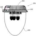
图1是从上方观察的已研制出来的光源的透视图;Figure 1 is a perspective view of the developed light source seen from above;
图2是图1的光源的侧视图;Figure 2 is a side view of the light source of Figure 1;
图3是从下方(但在光源的侧面)观察的类似于图1的光源的视图;Figure 3 is a view similar to the light source of Figure 1 from below (but on the side of the light source);
图4是与图3相同的视图,其中罩从光源上移走;Figure 4 is the same view as Figure 3 with the cover removed from the light source;
图5是具有图1的光源的灯具的侧视图;Figure 5 is a side view of a light fixture having the light source of Figure 1;
图6是从图5的灯具的下方观察的透视图,其中下盖被移走;并且FIG. 6 is a perspective view from below of the light fixture of FIG. 5 with the lower cover removed; and
图7是基于类似透视图的图6的灯具的剖视图。FIG. 7 is a cross-sectional view of the light fixture of FIG. 6 based on a similar perspective view.
具体实施方式Detailed ways
参照附图,这里示出的实施例是我们的早期申请之外的新发展。Referring to the drawings, the embodiments shown here are a new development beyond our earlier application.
参照图1至图4,光源101具有居中安装在PCB 103上的LED芯片单元102。通过穿过基座到达热量耗散器或散热器106的螺钉105,将该单元快速保持在LED基座104上。散热器具有多个插针107,以增加其表面积并允许热量传递到周围的空气。螺钉接合到散热器的盘108中,插针从该盘伸出,并且螺钉将PCB拉到与LED基座导热的状态。1 to 4 , the light source 101 has an
细节是,PCB、基座和盘上都被钻孔,用于向PCB供电的电源线(未示出),以便照亮LED。The details are that the PCB, base and pad are all drilled for power lines (not shown) to power the PCB in order to illuminate the LEDs.
基座具有围绕PCB的边沿109,在该边沿中铣削出一个圆形阵列的凹部110。3D打印的罩112具有一体的套环114,该一体的套环114具有布置成悬置在边沿109上的一系列唇缘115。因此,唇缘将罩保持在LED基座上。套环在其中装有一对弹簧棘爪116。罩在其中装有反光器117。The base has a
棘爪和凹部允许被夹住的一个罩围绕基座转动,以将反光器定向在期望的方向上。The pawls and recesses allow the clamped one cover to be rotated about the base to orient the reflector in the desired direction.
如图所示,反光器具有一定长度,沿着该长度,反光器朝着LED凹入弯曲。它还在横向于它的长度的横截面上具有尖头,从而在远离反光器的侧向方向上反射和传播入射在反光器上的光。该反光器并不具有像抛物线反光器或者实际上圆形截面的反光器那样强烈的定向效果,这两种反光器都被认为是可能的变型。而是,反光器将入射在反光器上的光传播出去,以提供广泛的方向性照明。它还遮挡了位于它后面的区域,否则该区域可能会被LED不需要地照亮。As shown, the reflector has a length along which the reflector curves concavely towards the LED. It also has prongs in cross section transverse to its length to reflect and propagate light incident on the reflector in a lateral direction away from the reflector. The reflector does not have as strong a directional effect as a parabolic reflector or a reflector with a practical circular cross-section, both of which are considered possible variants. Rather, the reflector spreads light incident on the reflector away to provide broad directional illumination. It also blocks out the area behind it that might otherwise be unnecessarily illuminated by the LEDs.
反光器可以是由聚合材料制成的,适当地是金属化为反光性的。或者,它可以是金属的。The reflector may be made of a polymeric material, suitably metallized to be reflective. Alternatively, it can be metallic.
现在转到图5至图7,用于灯标准件的灯具201(未示出)具有带有铰链203的固定环202,不透明的上盖204和透明的下盖205通过铰链203而被铰接到固定环。远离铰链,提供了封闭结构,特别是用于支撑在使用中从固定环向下延伸的透明盖。Turning now to Figures 5-7, a luminaire 201 (not shown) for a lamp standard has a retaining
固定环具有一体的板206,在该板上方是基本上常规的电源电路207,其被支撑在板208上。在板206下方,固定有相互接合的一圈间隔件208。它们承载有下板209,通过中心螺栓211将夹紧板210固定在该下板209上。两个板均具有各自的圆形切口212,214。下板切口的尺寸设计用以接纳多个光源101的LED基座104,其中光源的散热器盘108搁置在下板上。夹板切口接纳每个光源的散热器插针107。随着螺栓211的拧紧,光源被快速保持。它们的基座具有刻痕118,下板具有凸舌215。这些特征相互接合,其中LED基座被定向在预设方向上。在每个切口212周围均设置有角刻度216。因此,在组装时可以将罩旋转至预定角度。安装后,可以在下盖打开的情况下对罩及其反光器的角度进行最终调整。The retaining ring has an
本发明无意限于上述实施例的细节。例如,在不需要汽灯罩的外观的情况下,罩可以形成为比所示的具有更少的股线,从而给予更敞开的外观,并且具有更少的来自股线的二次发射。实际上,它可能是连续的并且透明的。此外,其可以仅被成形为围绕反光器的边缘的支撑件,其中支撑件仍然与调节套环是一体的。The invention is not intended to be limited to the details of the above-described embodiments. For example, where the appearance of a vapor lamp shade is not desired, the shade may be formed with fewer strands than shown, giving a more open appearance and having less secondary emissions from the strands. In fact, it may be continuous and transparent. Furthermore, it may only be shaped as a support around the edge of the reflector, wherein the support is still integral with the adjustment collar.
反光器可以比所示的更大,特别是在角度上更大。反光器也可以通过跨过罩的远端的内部的另一反光器来增强,以减轻光的集中。The reflector may be larger than shown, especially in angle. The reflector can also be enhanced by another reflector across the interior of the distal end of the hood to alleviate light concentration.
还可以设想,反光器可以集成在罩中,就像以菲涅耳透镜的方式围绕着一部分罩延伸的棱镜元件。替代性地是,可以对罩或对罩的残余部分进行3D打印,然后进行金属化处理。It is also envisaged that the reflector could be integrated in the cover, like a prismatic element extending around a portion of the cover in the manner of a Fresnel lens. Alternatively, the hood or remnants of the hood can be 3D printed and then metallized.
Claims (16)
Applications Claiming Priority (5)
| Application Number | Priority Date | Filing Date | Title |
|---|---|---|---|
| GB1707673.8 | 2017-05-12 | ||
| GBGB1707673.8AGB201707673D0 (en) | 2017-05-12 | 2017-05-12 | light source for a luminaire |
| GBGB1804286.1AGB201804286D0 (en) | 2018-03-16 | 2018-03-16 | Light source for a luminaire |
| GB1804286.1 | 2018-03-16 | ||
| PCT/GB2018/051281WO2018206979A1 (en) | 2017-05-12 | 2018-05-11 | Light source for a luminaire |
Publications (1)
| Publication Number | Publication Date |
|---|---|
| CN110832246Atrue CN110832246A (en) | 2020-02-21 |
Family
ID=62713025
Family Applications (1)
| Application Number | Title | Priority Date | Filing Date |
|---|---|---|---|
| CN201880031438.2APendingCN110832246A (en) | 2017-05-12 | 2018-05-11 | light source for lamps |
Country Status (6)
| Country | Link |
|---|---|
| US (1) | US10808892B2 (en) |
| EP (1) | EP3622215B1 (en) |
| CN (1) | CN110832246A (en) |
| AU (1) | AU2018266829B2 (en) |
| CA (1) | CA3062725A1 (en) |
| WO (1) | WO2018206979A1 (en) |
Citations (10)
| Publication number | Priority date | Publication date | Assignee | Title |
|---|---|---|---|---|
| US5408389A (en)* | 1993-09-07 | 1995-04-18 | Burlingame; Glen E. | Interrupted light source |
| CN101696772A (en)* | 2005-04-15 | 2010-04-21 | 阿隆株式会社 | Rotating lamp |
| CN101761792A (en)* | 2008-12-23 | 2010-06-30 | 富准精密工业(深圳)有限公司 | Light-emitting diode fixture and luminescence unit thereof |
| CN102388260A (en)* | 2009-01-27 | 2012-03-21 | 欧司朗股份有限公司 | light emitting device |
| CN102459991A (en)* | 2009-06-19 | 2012-05-16 | 皇家飞利浦电子股份有限公司 | Lamp assembly |
| CN102792087A (en)* | 2010-03-22 | 2012-11-21 | 欧司朗股份有限公司 | Lamp with reflector means and reflector element |
| CN203743909U (en)* | 2013-12-31 | 2014-07-30 | 北京交通大学长三角研究院 | High-dissipation LED lamp |
| CN204227320U (en)* | 2014-11-03 | 2015-03-25 | 嘉兴亚欧光电科技有限公司 | A kind of LED spotlight lens of improvement |
| US20160161082A1 (en)* | 2014-12-04 | 2016-06-09 | Chih-Chiang Huang | Warning lamp assembly |
| CN106610003A (en)* | 2015-10-26 | 2017-05-03 | 周晓东 | LED lamp with good radiating effect |
- 2018
- 2018-05-11CNCN201880031438.2Apatent/CN110832246A/enactivePending
- 2018-05-11AUAU2018266829Apatent/AU2018266829B2/enactiveActive
- 2018-05-11EPEP18733662.3Apatent/EP3622215B1/enactiveActive
- 2018-05-11CACA3062725Apatent/CA3062725A1/enactivePending
- 2018-05-11WOPCT/GB2018/051281patent/WO2018206979A1/ennot_activeCeased
- 2018-05-11USUS16/612,652patent/US10808892B2/enactiveActive
Patent Citations (10)
| Publication number | Priority date | Publication date | Assignee | Title |
|---|---|---|---|---|
| US5408389A (en)* | 1993-09-07 | 1995-04-18 | Burlingame; Glen E. | Interrupted light source |
| CN101696772A (en)* | 2005-04-15 | 2010-04-21 | 阿隆株式会社 | Rotating lamp |
| CN101761792A (en)* | 2008-12-23 | 2010-06-30 | 富准精密工业(深圳)有限公司 | Light-emitting diode fixture and luminescence unit thereof |
| CN102388260A (en)* | 2009-01-27 | 2012-03-21 | 欧司朗股份有限公司 | light emitting device |
| CN102459991A (en)* | 2009-06-19 | 2012-05-16 | 皇家飞利浦电子股份有限公司 | Lamp assembly |
| CN102792087A (en)* | 2010-03-22 | 2012-11-21 | 欧司朗股份有限公司 | Lamp with reflector means and reflector element |
| CN203743909U (en)* | 2013-12-31 | 2014-07-30 | 北京交通大学长三角研究院 | High-dissipation LED lamp |
| CN204227320U (en)* | 2014-11-03 | 2015-03-25 | 嘉兴亚欧光电科技有限公司 | A kind of LED spotlight lens of improvement |
| US20160161082A1 (en)* | 2014-12-04 | 2016-06-09 | Chih-Chiang Huang | Warning lamp assembly |
| CN106610003A (en)* | 2015-10-26 | 2017-05-03 | 周晓东 | LED lamp with good radiating effect |
Also Published As
| Publication number | Publication date |
|---|---|
| EP3622215B1 (en) | 2023-06-21 |
| EP3622215A1 (en) | 2020-03-18 |
| AU2018266829B2 (en) | 2023-05-11 |
| AU2018266829A1 (en) | 2019-12-05 |
| WO2018206979A1 (en) | 2018-11-15 |
| US20200208792A1 (en) | 2020-07-02 |
| US10808892B2 (en) | 2020-10-20 |
| EP3622215C0 (en) | 2023-06-21 |
| CA3062725A1 (en) | 2018-11-15 |
Similar Documents
| Publication | Publication Date | Title |
|---|---|---|
| US10295150B2 (en) | Asymmetrical optical system | |
| JP5702784B2 (en) | Daylight lighting apparatus and method with auxiliary lighting fixture | |
| EP3027963B1 (en) | Reflector for directed beam led illumination | |
| US6648490B2 (en) | Reflector lighting fixture, especially for in-the-floor, in-the-wall or in-the-ceiling lighting | |
| CN104976552A (en) | Lens device and LED light fixture | |
| CN204717510U (en) | A kind of lens devices and LED lamp | |
| CN107567567B (en) | Solid state lighting device and luminaire | |
| US20160223164A1 (en) | Wall washer lighting system with light emitter, optical lens and reflector | |
| JP6709345B1 (en) | lighting equipment | |
| US8403537B2 (en) | Lighting apparatus | |
| US20050213336A1 (en) | Four segment reflector | |
| US10808892B2 (en) | Light source for a luminaire | |
| HK40024549A (en) | Light source for a luminaire | |
| US10801698B2 (en) | High visual comfort road and urban LED lighting | |
| EP3772609A1 (en) | Reflector system for reducing the unified glare rating from luminaires with led technology | |
| TWI524036B (en) | Light apparatus | |
| KR20090014749A (en) | Illumination light irradiation device | |
| KR20110029042A (en) | Unit optics for lighting and lighting equipment using the same | |
| JP2016115673A (en) | Luminaire having reflection optical system | |
| US10119680B2 (en) | Retrofit light emitting diode fixture for a back box | |
| KR101354475B1 (en) | Boundary led light | |
| KR101694746B1 (en) | Illumination lens for light emitting diode | |
| KR20180137843A (en) | Lighting apparatus with light-diffusing function | |
| KR20160019916A (en) | Unit Optical Device For Lighting and The Lighting Apparatus Thereby | |
| CN102859274A (en) | LED distribution device, LED lamp and LED apparatus |
Legal Events
| Date | Code | Title | Description |
|---|---|---|---|
| PB01 | Publication | ||
| PB01 | Publication | ||
| SE01 | Entry into force of request for substantive examination | ||
| SE01 | Entry into force of request for substantive examination | ||
| REG | Reference to a national code | Ref country code:HK Ref legal event code:DE Ref document number:40024549 Country of ref document:HK | |
| RJ01 | Rejection of invention patent application after publication | ||
| RJ01 | Rejection of invention patent application after publication | Application publication date:20200221 |