CN110831532B - Guide wire for plasma - Google Patents
Guide wire for plasmaDownload PDFInfo
- Publication number
- CN110831532B CN110831532BCN201780092569.7ACN201780092569ACN110831532BCN 110831532 BCN110831532 BCN 110831532BCN 201780092569 ACN201780092569 ACN 201780092569ACN 110831532 BCN110831532 BCN 110831532B
- Authority
- CN
- China
- Prior art keywords
- insulating resin
- resin tube
- coil
- mandrel
- guide wire
- Prior art date
- Legal status (The legal status is an assumption and is not a legal conclusion. Google has not performed a legal analysis and makes no representation as to the accuracy of the status listed.)
- Active
Links
Images


Classifications
- A—HUMAN NECESSITIES
- A61—MEDICAL OR VETERINARY SCIENCE; HYGIENE
- A61B—DIAGNOSIS; SURGERY; IDENTIFICATION
- A61B18/00—Surgical instruments, devices or methods for transferring non-mechanical forms of energy to or from the body
- A61B18/04—Surgical instruments, devices or methods for transferring non-mechanical forms of energy to or from the body by heating
- A61B18/12—Surgical instruments, devices or methods for transferring non-mechanical forms of energy to or from the body by heating by passing a current through the tissue to be heated, e.g. high-frequency current
- A61B18/14—Probes or electrodes therefor
- A—HUMAN NECESSITIES
- A61—MEDICAL OR VETERINARY SCIENCE; HYGIENE
- A61B—DIAGNOSIS; SURGERY; IDENTIFICATION
- A61B17/00—Surgical instruments, devices or methods
- A61B17/22—Implements for squeezing-off ulcers or the like on inner organs of the body; Implements for scraping-out cavities of body organs, e.g. bones; for invasive removal or destruction of calculus using mechanical vibrations; for removing obstructions in blood vessels, not otherwise provided for
- A—HUMAN NECESSITIES
- A61—MEDICAL OR VETERINARY SCIENCE; HYGIENE
- A61B—DIAGNOSIS; SURGERY; IDENTIFICATION
- A61B18/00—Surgical instruments, devices or methods for transferring non-mechanical forms of energy to or from the body
- A61B18/04—Surgical instruments, devices or methods for transferring non-mechanical forms of energy to or from the body by heating
- A61B18/042—Surgical instruments, devices or methods for transferring non-mechanical forms of energy to or from the body by heating using additional gas becoming plasma
- A—HUMAN NECESSITIES
- A61—MEDICAL OR VETERINARY SCIENCE; HYGIENE
- A61M—DEVICES FOR INTRODUCING MEDIA INTO, OR ONTO, THE BODY; DEVICES FOR TRANSDUCING BODY MEDIA OR FOR TAKING MEDIA FROM THE BODY; DEVICES FOR PRODUCING OR ENDING SLEEP OR STUPOR
- A61M25/00—Catheters; Hollow probes
- A61M25/01—Introducing, guiding, advancing, emplacing or holding catheters
- A61M25/09—Guide wires
- A—HUMAN NECESSITIES
- A61—MEDICAL OR VETERINARY SCIENCE; HYGIENE
- A61B—DIAGNOSIS; SURGERY; IDENTIFICATION
- A61B17/00—Surgical instruments, devices or methods
- A61B17/22—Implements for squeezing-off ulcers or the like on inner organs of the body; Implements for scraping-out cavities of body organs, e.g. bones; for invasive removal or destruction of calculus using mechanical vibrations; for removing obstructions in blood vessels, not otherwise provided for
- A61B2017/22038—Implements for squeezing-off ulcers or the like on inner organs of the body; Implements for scraping-out cavities of body organs, e.g. bones; for invasive removal or destruction of calculus using mechanical vibrations; for removing obstructions in blood vessels, not otherwise provided for with a guide wire
- A61B2017/22042—Details of the tip of the guide wire
- A—HUMAN NECESSITIES
- A61—MEDICAL OR VETERINARY SCIENCE; HYGIENE
- A61B—DIAGNOSIS; SURGERY; IDENTIFICATION
- A61B18/00—Surgical instruments, devices or methods for transferring non-mechanical forms of energy to or from the body
- A61B2018/00053—Mechanical features of the instrument of device
- A61B2018/00059—Material properties
- A61B2018/00071—Electrical conductivity
- A61B2018/00083—Electrical conductivity low, i.e. electrically insulating
- A—HUMAN NECESSITIES
- A61—MEDICAL OR VETERINARY SCIENCE; HYGIENE
- A61B—DIAGNOSIS; SURGERY; IDENTIFICATION
- A61B18/00—Surgical instruments, devices or methods for transferring non-mechanical forms of energy to or from the body
- A61B2018/00315—Surgical instruments, devices or methods for transferring non-mechanical forms of energy to or from the body for treatment of particular body parts
- A61B2018/00345—Vascular system
- A61B2018/00404—Blood vessels other than those in or around the heart
- A61B2018/0041—Removal of thrombosis
- A—HUMAN NECESSITIES
- A61—MEDICAL OR VETERINARY SCIENCE; HYGIENE
- A61B—DIAGNOSIS; SURGERY; IDENTIFICATION
- A61B18/00—Surgical instruments, devices or methods for transferring non-mechanical forms of energy to or from the body
- A61B18/04—Surgical instruments, devices or methods for transferring non-mechanical forms of energy to or from the body by heating
- A61B18/12—Surgical instruments, devices or methods for transferring non-mechanical forms of energy to or from the body by heating by passing a current through the tissue to be heated, e.g. high-frequency current
- A61B18/14—Probes or electrodes therefor
- A61B2018/1405—Electrodes having a specific shape
- A61B2018/1417—Ball
- A—HUMAN NECESSITIES
- A61—MEDICAL OR VETERINARY SCIENCE; HYGIENE
- A61M—DEVICES FOR INTRODUCING MEDIA INTO, OR ONTO, THE BODY; DEVICES FOR TRANSDUCING BODY MEDIA OR FOR TAKING MEDIA FROM THE BODY; DEVICES FOR PRODUCING OR ENDING SLEEP OR STUPOR
- A61M25/00—Catheters; Hollow probes
- A61M25/01—Introducing, guiding, advancing, emplacing or holding catheters
- A61M25/09—Guide wires
- A61M2025/09058—Basic structures of guide wires
- A61M2025/09083—Basic structures of guide wires having a coil around a core
- A—HUMAN NECESSITIES
- A61—MEDICAL OR VETERINARY SCIENCE; HYGIENE
- A61M—DEVICES FOR INTRODUCING MEDIA INTO, OR ONTO, THE BODY; DEVICES FOR TRANSDUCING BODY MEDIA OR FOR TAKING MEDIA FROM THE BODY; DEVICES FOR PRODUCING OR ENDING SLEEP OR STUPOR
- A61M25/00—Catheters; Hollow probes
- A61M25/01—Introducing, guiding, advancing, emplacing or holding catheters
- A61M25/09—Guide wires
- A61M2025/09108—Methods for making a guide wire
- A—HUMAN NECESSITIES
- A61—MEDICAL OR VETERINARY SCIENCE; HYGIENE
- A61M—DEVICES FOR INTRODUCING MEDIA INTO, OR ONTO, THE BODY; DEVICES FOR TRANSDUCING BODY MEDIA OR FOR TAKING MEDIA FROM THE BODY; DEVICES FOR PRODUCING OR ENDING SLEEP OR STUPOR
- A61M25/00—Catheters; Hollow probes
- A61M25/01—Introducing, guiding, advancing, emplacing or holding catheters
- A61M25/09—Guide wires
- A61M2025/09175—Guide wires having specific characteristics at the distal tip
Landscapes
- Health & Medical Sciences (AREA)
- Life Sciences & Earth Sciences (AREA)
- Surgery (AREA)
- Engineering & Computer Science (AREA)
- Animal Behavior & Ethology (AREA)
- General Health & Medical Sciences (AREA)
- Veterinary Medicine (AREA)
- Public Health (AREA)
- Biomedical Technology (AREA)
- Heart & Thoracic Surgery (AREA)
- Medical Informatics (AREA)
- Molecular Biology (AREA)
- Nuclear Medicine, Radiotherapy & Molecular Imaging (AREA)
- Physics & Mathematics (AREA)
- Otolaryngology (AREA)
- Plasma & Fusion (AREA)
- Orthopedic Medicine & Surgery (AREA)
- Vascular Medicine (AREA)
- Biophysics (AREA)
- Pulmonology (AREA)
- Anesthesiology (AREA)
- Hematology (AREA)
- Media Introduction/Drainage Providing Device (AREA)
- Surgical Instruments (AREA)
Abstract
Translated fromChinese
Description
Translated fromChinese技术领域technical field
本发明涉及一种等离子体用导丝。The invention relates to a guide wire for plasma.
背景技术Background technique
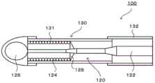
一直以来,公知一种等离子体用导丝。例如,专利文献1中公开一种等离子体用导丝100,如图6所示,该等离子体用导丝100具备导丝主体120、和覆盖该导丝主体120的绝缘树脂管130。导丝主体120是在芯轴122的前端侧的区域的外周卷绕线圈124并在芯轴122的前端和线圈124的前端接合有片材126的部件。线圈124的后端利用线圈-芯轴接合部125而接合于芯轴122。绝缘树脂管130由第一绝缘树脂管131和第二绝缘树脂管132构成。第一绝缘树脂管131设于线圈124的外周,并从片材126延伸至线圈-芯轴接合部125的后方。第二绝缘树脂管132设于芯轴122的外周,接合于第一绝缘树脂管131的后端,并从第一绝缘树脂管131的后端延伸至芯轴122的后方。在这样的等离子体用导丝100中,在芯轴122的后端连接高频发生器,在片材126的前端与对置于该前端的其它部件的电极之间产生等离子体。由此,能够利用等离子体来使血管的堵塞部贯通。Conventionally, a guide wire for plasma has been known. For example, Patent Document 1 discloses a
现有技术文献prior art literature
专利文献patent documents
专利文献1:国际公开第2016/134152号手册Patent Document 1: International Publication No. 2016/134152 Handbook
发明内容Contents of the invention
发明所要解决的课题The problem to be solved by the invention
然而,专利文献1中并未记载由不同的材料构成第一绝缘树脂管131和第二绝缘树脂管132的这一点。因此,若由较硬的相同的树脂构成第一绝缘树脂管131和第二绝缘树脂管132,则导丝主体120的卷绕有线圈124的部分的操作性降低。另一方面,若与第一绝缘树脂管131相比,第二绝缘树脂管132构成为较软,则在第一绝缘树脂管131的不存在线圈124的部分产生刚性间隙。因此,在向前端方向按压等离子体用导丝100时,柔软的第一绝缘树脂管131在该部分挠曲,有操作性降低的问题。However, Patent Document 1 does not describe that the first
本发明是为了解决这样的课题而完成的,其主要目的在于,提高等离子体用导丝的前端侧(即、芯轴的卷绕有线圈的部分或者/以及第一绝缘树脂管的不存在线圈的部分)的操作性。The present invention has been made to solve such problems, and its main purpose is to improve the front end side of the plasma guide wire (that is, the part of the mandrel where the coil is wound or/and the coil-free part of the first insulating resin tube). part) operability.
用于解决课题的方案Solution to the problem
本发明的等离子体用导丝具备:The guide wire for plasma of the present invention has:
芯轴;Mandrel;
线圈,其卷绕于上述芯轴的前端侧的区域的外周;a coil wound around an outer periphery of a region on the front end side of the mandrel;
片材,其接合于上述芯轴的前端和上述线圈的前端;a sheet joined to the front end of the mandrel and the front end of the coil;
线圈-芯轴接合部,其接合上述线圈的后端与上述芯轴;a coil-mandrel joint that joins the rear end of the coil with the mandrel;
第一绝缘树脂管,其设于上述线圈的外周,并从上述片材延伸至上述线圈-芯轴接合部的后方;a first insulating resin tube provided on the outer periphery of the coil and extending from the sheet to the rear of the coil-mandrel junction;
第二绝缘树脂管,其设于上述芯轴的外周,接合于上述第一绝缘树脂管的后端,从上述第一绝缘树脂管的后端延伸至上述芯轴的后方,并且比上述第一绝缘树脂管硬;以及The second insulating resin tube is provided on the outer periphery of the mandrel, is joined to the rear end of the first insulating resin tube, extends from the rear end of the first insulating resin tube to the rear of the mandrel, and is larger than the first insulating resin tube. The insulating resin tube is hard; and
第三绝缘树脂管,其设于上述第一绝缘树脂管的内周的比面向上述线圈的后端的位置靠后方的区域的至少一部分。The third insulating resin tube is provided in at least a part of an area of the inner periphery of the first insulating resin tube that is behind a position facing the rear end of the coil.
在该等离子体用导丝中,在比较柔软的第一绝缘树脂管的不存在线圈的部分产生刚性间隙,但该刚性间隙因第三绝缘树脂管而减少,因而能够抑制该部分的挠曲。并且,在比较柔软的第一绝缘树脂管的覆盖线圈的部分未设置第三绝缘树脂管。因此,能够提高等离子体用导丝的前端侧即芯轴的卷绕有线圈的部分或者/以及第一绝缘树脂管的不存在线圈的部分的操作性。In this guide wire for plasma, a rigid gap is formed in a portion of the relatively flexible first insulating resin tube where the coil does not exist, but the rigid gap is reduced by the third insulating resin tube, so that bending of this portion can be suppressed. In addition, the third insulating resin tube is not provided in the portion of the relatively flexible first insulating resin tube covering the coil. Therefore, it is possible to improve the operability of the portion of the mandrel on which the coil is wound and/or the portion of the first insulating resin tube where the coil is not present, which is the distal end side of the plasma guide wire.
附图说明Description of drawings
图1是等离子体用导丝10的主视图。FIG. 1 is a front view of a
图2是图1的A-A剖视图。Fig. 2 is a cross-sectional view along line A-A of Fig. 1 .
图3是图2的部分B的放大图。FIG. 3 is an enlarged view of part B of FIG. 2 .
图4是其它实施方式的说明图。FIG. 4 is an explanatory diagram of another embodiment.
图5是其它实施方式的说明图。FIG. 5 is an explanatory diagram of another embodiment.
图6是现有的等离子体用导丝100的剖视图。FIG. 6 is a cross-sectional view of a
具体实施方式Detailed ways
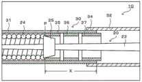
以下,参照附图对本发明的优选实施方式进行说明。图1是等离子体用导丝10的主视图,图2是图1的A-A剖视图,图3是图2的部分B的放大图。Hereinafter, preferred embodiments of the present invention will be described with reference to the drawings. FIG. 1 is a front view of a
如图1所示,本实施方式的等离子体用导丝10具备导丝主体20和覆盖该导丝主体20的绝缘树脂管30。等离子体用导丝10的全长例如为1800~2000mm。等离子体用导丝10也被称作高频(RF)用导丝。As shown in FIG. 1 , the
如图2所示,导丝主体20具备芯轴22、线圈24、线圈-芯轴接合部25、以及片材26。As shown in FIG. 2 , the wire
芯轴22由导电性材料构成,具备轴后端部22a和轴前端部22b。轴前端部22b交替地设有圆筒部和锥形部,直径趋向配置于前端的圆筒部而变小。芯轴22例如由不锈钢(奥氏体不锈钢、马氏体不锈钢、铁素体不锈钢、奥氏体-铁素体双相不锈钢、沉淀硬化不锈钢等)、超弹性合金(Ni-Ti合金等)、钢琴线、钨等材料构成。The
线圈24通过将一根线材卷绕成螺旋状来形成,其卷绕于芯轴22的前端侧的区域的外周。线圈24对等离子体用导丝10赋予柔软性。来自高频发生器40的电流在经过芯轴22到达线圈-芯轴接合部25后,分支地流向芯轴22和线圈24。因此,流动于线圈24的电流比从芯轴22的后端流动至线圈-芯轴接合部25的电流小。线圈24的全长例如为40mm~50mm,线圈24的外径例如为0.24mm~0.25mm,线材的直径例如为0.03~0.08mm。线材例如由不锈钢(奥氏体不锈钢、马氏体不锈钢、铁素体不锈钢、奥氏体-铁素体双相不锈钢、沉淀硬化不锈钢等)、超弹性合金(Ni-Ti合金等)、不透射线金属(铂、金、钨等)材料构成。此外,线圈24也可以通过将多个线材卷绕成螺旋状来形成。并且,线圈24也可以将绞合多个线材而成的绞线卷绕成螺旋状来形成。The
线圈-芯轴接合部25将线圈24的后端与芯轴22接合,由焊料构成。作为焊料,例如可以举出铝合金焊料、银焊料、金焊料、锌、Sn-Pb合金、Pb-Ag合金、Sn-Ag合金等。此外,对于线圈24而言,除线圈24的后端以外,也可以在线圈24的前端、线圈24的中间也由焊料而接合于芯轴22。The coil-mandrel
片材26是通过焊接芯轴22的前端和线圈24的前端而形成的曲面形状的部件。作为焊接,优选电弧焊。并且,作为电弧焊,可以是TIG保护焊、等离子体焊接等非自耗电极式,也可以是涂层电弧焊、MAG焊、二氧化碳气体保护焊、氩气和二氧化碳气体保护焊、MIG焊、埋弧焊等自耗电极式,但优选非自耗电极式,更优选TIG保护焊。The
如图2所示,绝缘树脂管30具备第一绝缘树脂管31、第二绝缘树脂管32、以及第三绝缘树脂管33。As shown in FIG. 2 , the insulating
第一绝缘树脂管31设于线圈24的外周,从片材26延伸至线圈-芯轴接合部25的后方。第一绝缘树脂管31的前端接合于片材26。第一绝缘树脂管31例如由氟树脂(PFA)构成。第一绝缘树脂管31的全长例如为100mm~115mm,第一绝缘树脂管31的外径例如为0.3mm~0.35mm,第一绝缘树脂管31的厚度例如为0.015mm~0.02mm。The first insulating
第二绝缘树脂管32设于芯轴22的外周,从第一绝缘树脂管31的后端延伸至芯轴22的后方。第二绝缘树脂管32与第一绝缘树脂管31在接合部34接合。接合部34通过用粘接剂接合第二绝缘树脂管32的前端的内表面与第一绝缘树脂管31的后端的外表面来形成。作为粘接剂,例如可以举出环氧树脂、丙烯酸树脂等。第二绝缘树脂管32例如由聚酰亚胺树脂构成。第二绝缘树脂管32的全长例如为1800mm~1900mm,第二绝缘树脂管32的外径例如为0.32mm~0.36mm,第二绝缘树脂管32的厚度例如为0.005mm~0.015mm。第二绝缘树脂管32的硬度比第一绝缘树脂管31的硬度硬。此外,接合部34也可以由粘接剂而与芯轴22接合。The second insulating
第三绝缘树脂管33配置于第一绝缘树脂管31的内侧。第三绝缘树脂管33的前端抵接于线圈-芯轴接合部25。如图3所示,第三绝缘树脂管33设置为覆盖第一绝缘树脂管31的内周的比面向线圈24的后端的位置P靠后方的区域X的整个面。第三绝缘树脂管33延伸至比第一绝缘树脂管31的后端更靠后方,从内侧覆盖第一绝缘树脂管31与第二绝缘树脂管32之间的接合部34。第三绝缘树脂管33起到阻止第一绝缘树脂管31与芯轴22接触的作用。第三绝缘树脂管33例如由聚酰亚胺树脂构成。第三绝缘树脂管33的全长例如为60mm~80mm,第三绝缘树脂管33的外径例如为0.23mm~0.24mm,第三绝缘树脂管33的厚度例如为0.015mm~0.02mm。第三绝缘树脂管33的硬度比第一绝缘树脂管31的硬度硬。第三绝缘树脂管33也可以由粘接剂而在前端及后端与芯轴22粘接。The third insulating
接下来,对等离子体用导丝10的使用例进行说明。等离子体用导丝10是用于经皮冠状动脉形成术(PCI)的医疗用机械器具,在将气囊、支架等器件引导至血管的堵塞部时使用。在等离子体用导丝10中,芯轴22的前端部成为远端部,芯轴22的后端部成为近端部。等离子体用导丝10的远端部插入血管内,近端部由医师等技术人员操作。若远端部到达血管内的堵塞部,则技术人员压入或拉动等离子体用导丝10又或者使之旋转,以便片材26贯通堵塞部。但是,若堵塞部钙化而变硬,则仅进行这样的操作的话,有时无法使堵塞部贯通。在该情况下,使其它等离子体用导丝10在血管内逆行,在堵塞部的相反侧配置该其它等离子体用导丝10的片材26。由此,成为一对片材26隔着堵塞部而对置的状态。通过在该一对片材26之间施加高频电压,从而在一对片材26之间产生等离子体,破坏堵塞部。Next, an example of use of the
此处,在等离子体用导丝10中,在比较柔软的第一绝缘树脂管31的不存在线圈24的部分产生刚性间隙,但该刚性间隙因第三绝缘树脂管33而减少。因此,能够抑制该部分的挠曲。并且,在比较柔软的第一绝缘树脂管31的覆盖线圈24的部分未设置第三绝缘树脂管33。因此,能够提高等离子体用导丝10的前端侧即芯轴22的卷绕有线圈24的部分的操作性。Here, in the
根据以上说明的本实施方式的等离子体用导丝10,能够提高等离子体用导丝10的前端侧(即,芯轴22的卷绕有线圈24的部分或者/以及第一绝缘树脂管的不存在线圈的部分)的操作性。According to the
并且,一般有越柔软的树脂的耐热性越低、越坚硬的树脂的耐热性越高的倾向。由于第一绝缘树脂管31比较柔软,所以耐热性较低,若与流动高频电流而成为高温的芯轴22直接接触,则有无法维持绝缘性的担忧。但是,由于第三绝缘树脂管33起到阻止第一绝缘树脂管31与芯轴22的接触的作用,所以容易确保第一绝缘树脂管31的绝缘性。此外,第一绝缘树脂管31有时与线圈24接触,但线圈24的温度不会变得那么高,从而不会对绝缘性产生妨碍。这是因为:在产生等离子体时流动于线圈24的电流比从芯轴22的后端流动至线圈-芯轴接合部25的电流小。In addition, generally, the softer resin tends to have lower heat resistance, and the harder resin tends to have higher heat resistance. Since the first insulating
另外,由于第三绝缘树脂管33比第一绝缘树脂管31硬,所以能够更加减少在第一绝缘树脂管31的不存在线圈24的部分产生的刚性间隙。In addition, since the third insulating
又且,由于第三绝缘树脂管33设置为从内侧覆盖第一绝缘树脂管31与第二绝缘树脂管32之间的接合部34,所以更容易确保接合部34的绝缘性。Furthermore, since the third insulating
再者,由于在流动于线圈24的电流与流动于芯轴22的电流合流而电力负荷变大的线圈-芯轴接合部25抵接有第三绝缘树脂管33,所以更容易确保线圈-芯轴接合部25的绝缘性。Furthermore, since the third insulating
而且,由于第三绝缘树脂管33遍及第一绝缘树脂管31的内周的比面向线圈的后端的位置P靠后方的整个区域X设置,所以更加减少在第一绝缘树脂管31的不存在线圈24的部分产生的刚性间隙,并且也更容易确保第一绝缘树脂管31的绝缘性。Furthermore, since the third insulating
此外,本发明不限定于上述的实施方式,当然在属于本发明的技术范围的范围内能够以各种方式实施。In addition, this invention is not limited to embodiment mentioned above, Of course, it can implement in various forms within the range belonging to the technical scope of this invention.
在上述的实施方式中,第三绝缘树脂管33遍及第一绝缘树脂管31的内周的比面向线圈24的后端的位置P靠后方的整个区域X设置,但也可以设于该区域X的一部分。例如也可以分割第三绝缘树脂管33,而如图4所示地成为第三绝缘树脂管35、36、37。此外,图4中,对与上述的实施方式相同的构成要素标注相同的符号。这样,第一绝缘树脂管31的不存在线圈24的部分的刚性间隙也因第三绝缘树脂管35、36、37而减少。因此,能够抑制在该部分的挠曲。并且,在第一绝缘树脂管31的覆盖线圈24的部分未设置第三绝缘树脂管35、36、37。因此,提高等离子体用导丝10的前端侧即芯轴22的卷绕有线圈24的部分的操作性。此外,第三绝缘树脂管35、36、37优选设置为阻止第一绝缘树脂管31与芯轴22的接触。并且,可以采用第三绝缘树脂管35、36、37中任一个,也可以采用其中任两个。在采用了第三绝缘树脂管35的情况下,更容易确保线圈-芯轴接合部25的绝缘性,在采用了第三绝缘树脂管37的情况下,更容易确保接合部34的绝缘性。In the above-described embodiment, the third insulating
在上述的实施方式中,在使等离子体用导丝10的片材26与其它等离子体用导丝10的片材26隔着血管内的堵塞部而对置的状态下,在该一对片材26之间产生等离子体,但也可以利用其它方法来产生等离子体。例如,也可以在插入患者的血管内的等离子体用导丝10的片材26与配置于该患者的皮肤的电极之间产生等离子体。或者,也可以使两根等离子体用导丝10在血管内并行,在堵塞部的附近,在彼此的片材26间产生等离子体,来破坏堵塞部。In the above-mentioned embodiment, in the state where the
在上述的实施方式中,也可以如图5所示,在第一绝缘树脂管31的前端设有由耐热性树脂(例如聚酰亚胺树脂等)构成的环状的卡圈38,并接合该卡圈38和片材26。此外,图5中,对与上述的实施方式相同的构成要素标注了相同的符号。这样,能够防止第一绝缘树脂管31的前端因热而损伤的情况。In the above-mentioned embodiment, as shown in FIG. 5, an
在上述的实施方式中,第二绝缘树脂管32也可以延伸至轴后端部22a的端面。或者,芯轴22的轴后端部22a的未被第二绝缘树脂管32包覆的部分也可以由其它的绝缘树脂管(第四绝缘树脂管)包覆。In the above-described embodiment, the second insulating
在上述的实施方式中,作为第三绝缘树脂管33,使用了比第一绝缘树脂管31硬的部件,但没有特别限定。例如,作为第三绝缘树脂管33,可以使用硬度与第一绝缘树脂管31的硬度相同的部件,也可以使用比第一绝缘树脂管31软的部件。即便这样,也能够减少第一绝缘树脂管31的不存在线圈24的部分的刚性间隙,因而提高等离子体用导丝10的前端侧的操作性。其中,作为第三绝缘树脂管33,使用硬度比第一绝缘树脂管31的硬度硬的部件的情况,能够更加减少刚性间隙,因而优选。In the above-described embodiment, a member harder than the first insulating
在上述的实施方式中,作为第三绝缘树脂管33,使用了硬度比第一绝缘树脂管31的材料硬的材料,但没有特别限定。例如,作为第三绝缘树脂管33,也可以使用与第一绝缘树脂管31相同的材料并且比第一绝缘树脂管31厚的部件。这样,也能够使第三绝缘树脂管33的硬度比第一绝缘树脂管31硬。此外,构成第一绝缘树脂管31、第二绝缘树脂管32、以及第三绝缘树脂管33的材料的硬度是指基于肖氏硬度的硬度、或者基于计示硬度的硬度。因此,上述材料的硬度使用公知的试验机来测定即可。In the above-described embodiment, a material whose hardness is harder than that of the first insulating
此外,本发明的等离子体用导丝没有特别限定,但例如也能够如下构成。In addition, although the guide wire for plasma of this invention is not specifically limited, For example, it can also be comprised as follows.
在本发明的等离子体用导丝中,上述第三绝缘树脂管也可以设置为阻止上述第一绝缘树脂管与上述芯轴的接触。一般有越柔软的树脂的耐热性越低、越坚硬的树脂的耐热性越高的倾向。由于第一绝缘树脂管比较柔软,所以耐热性较低,若与流动高频电流而成为高温的芯轴直接接触,则有无法维持绝缘性的担忧。此处,由于第三绝缘树脂管设置为阻止第一绝缘树脂管与芯轴的接触,所以容易确保第一绝缘树脂管的绝缘性。In the guide wire for plasma of the present invention, the third insulating resin tube may be provided so as to prevent the first insulating resin tube from coming into contact with the mandrel. Generally, the softer resin tends to have lower heat resistance, and the harder resin tends to have higher heat resistance. Since the first insulating resin tube is relatively soft, it has low heat resistance, and if it comes into direct contact with a high-temperature mandrel through which a high-frequency current flows, the insulation may not be maintained. Here, since the third insulating resin tube is provided so as to prevent the contact of the first insulating resin tube with the mandrel, it is easy to secure the insulation of the first insulating resin tube.
在本发明的等离子体用导丝中,上述第三绝缘树脂管也可以比上述第一绝缘树脂管硬。这样一来,能够更加减少在第一绝缘树脂管的不存在线圈的部分产生的刚性间隙。In the plasma guide wire of the present invention, the third insulating resin tube may be harder than the first insulating resin tube. In this way, it is possible to further reduce the rigid gap generated in the portion of the first insulating resin tube where no coil exists.
在本发明的等离子体用导丝中,上述第三绝缘树脂管也可以设置为覆盖上述第一绝缘树脂管与上述第二绝缘树脂管之间的接合位置。这样一来,更容易确保第一绝缘树脂管与第二绝缘树脂管之间的接合位置的绝缘性。In the guide wire for plasma according to the present invention, the third insulating resin tube may be provided so as to cover a joining position between the first insulating resin tube and the second insulating resin tube. In this way, it becomes easier to ensure the insulation of the joining position between the first insulating resin tube and the second insulating resin tube.
在本发明的等离子体用导丝中,上述第三绝缘树脂管也可以抵接于上述线圈-芯轴接合部。这样一来,由于在流动于线圈的电流与流动于芯轴的电流合流而电力负荷变大的线圈-芯轴接合部抵接有第三绝缘树脂管,所以更容易确保线圈-芯轴接合部的绝缘性。In the guide wire for plasma of the present invention, the third insulating resin tube may be in contact with the coil-mandrel junction. In this way, since the third insulating resin tube abuts against the coil-mandrel junction where the electric current flowing through the coil and the current flowing through the mandrel combine to increase the power load, it is easier to secure the coil-mandrel junction. insulation.
在本发明的等离子体用导丝中,上述第三绝缘树脂管也可以遍及上述第一绝缘树脂管的内周的比面向上述线圈的后端的位置靠后方的整个区域设置。这样一来,更加减少在第一绝缘树脂管的不存在线圈的部分产生的刚性间隙,并且也更容易确保第一绝缘树脂管的绝缘性。In the guide wire for plasma according to the present invention, the third insulating resin tube may be provided over the entire inner circumference of the first insulating resin tube behind a position facing the rear end of the coil. In this way, the rigid gap generated in the portion of the first insulating resin tube where no coil exists is further reduced, and it is also easier to ensure the insulation of the first insulating resin tube.
工业上的可利用性Industrial availability
本发明例如能够用于在经皮冠状动脉形成术(PCI)所使用的医疗用机械器具中。The present invention can be used, for example, in a medical device used in percutaneous coronary angioplasty (PCI).
符号的说明Explanation of symbols
10—等离子体用导丝,20—导丝主体,22—芯轴,22a—轴后端部,22b—轴前端部,24—线圈,25—线圈-芯轴接合部,26—片材,30—绝缘树脂管,31—第一绝缘树脂管,32—第二绝缘树脂管,33—第三绝缘树脂管,34—接合部,35、36、37—第三绝缘树脂管,38—卡圈,40—高频发生器,100—等离子体用导丝,120—导丝主体,122—芯轴,124—线圈,125—芯轴接合部,126—片材,130—绝缘树脂管,131—第一绝缘树脂管,132—第二绝缘树脂管。10—the guide wire for plasma, 20—the main body of the guide wire, 22—the mandrel, 22a—the rear end of the shaft, 22b—the front end of the shaft, 24—the coil, 25—the joint between the coil and the mandrel, 26—the sheet, 30—insulating resin tube, 31—first insulating resin tube, 32—second insulating resin tube, 33—third insulating resin tube, 34—joint portion, 35, 36, 37—third insulating resin tube, 38—card Coil, 40—high frequency generator, 100—guide wire for plasma, 120—guide wire main body, 122—mandrel, 124—coil, 125—mandrel joint, 126—sheet, 130—insulating resin tube, 131—the first insulating resin pipe, 132—the second insulating resin pipe.
Claims (12)
Translated fromChineseApplications Claiming Priority (1)
| Application Number | Priority Date | Filing Date | Title |
|---|---|---|---|
| PCT/JP2017/023928WO2019003382A1 (en) | 2017-06-29 | 2017-06-29 | Plasma guide wire |
Publications (2)
| Publication Number | Publication Date |
|---|---|
| CN110831532A CN110831532A (en) | 2020-02-21 |
| CN110831532Btrue CN110831532B (en) | 2023-03-21 |
Family
ID=64741212
Family Applications (1)
| Application Number | Title | Priority Date | Filing Date |
|---|---|---|---|
| CN201780092569.7AActiveCN110831532B (en) | 2017-06-29 | 2017-06-29 | Guide wire for plasma |
Country Status (5)
| Country | Link |
|---|---|
| US (1) | US11653970B2 (en) |
| EP (2) | EP4279006A3 (en) |
| JP (1) | JP6724251B2 (en) |
| CN (1) | CN110831532B (en) |
| WO (1) | WO2019003382A1 (en) |
Families Citing this family (3)
| Publication number | Priority date | Publication date | Assignee | Title |
|---|---|---|---|---|
| WO2020246037A1 (en)* | 2019-06-07 | 2020-12-10 | 朝日インテック株式会社 | Guidewire |
| JP2023092857A (en)* | 2021-12-22 | 2023-07-04 | 朝日インテック株式会社 | plasma guide wire |
| JP2023169523A (en)* | 2022-05-17 | 2023-11-30 | 朝日インテック株式会社 | plasma guide wire |
Citations (8)
| Publication number | Priority date | Publication date | Assignee | Title |
|---|---|---|---|---|
| US5546948A (en)* | 1990-08-21 | 1996-08-20 | Boston Scientific Corporation | Ultrasound imaging guidewire |
| CN1939551A (en)* | 2005-09-28 | 2007-04-04 | 朝日印帝克股份有限公司 | Medical leading wire and manufacture thereof |
| CN101554507A (en)* | 2003-07-17 | 2009-10-14 | 泰尔茂株式会社 | Guide wire |
| JP2010000222A (en)* | 2008-06-20 | 2010-01-07 | Piolax Medical Device:Kk | Guide wire, and its manufacturing method |
| CN102160910A (en)* | 2010-02-19 | 2011-08-24 | 朝日英达科株式会社 | Guidewire |
| CN102441222A (en)* | 2010-10-08 | 2012-05-09 | 北京天地和协科技有限公司 | Coaxial composite wire and manufacturing method and application thereof |
| CN102470010A (en)* | 2009-09-15 | 2012-05-23 | 奥林巴斯医疗株式会社 | High-frequency treatment tool |
| CN104023783A (en)* | 2012-03-29 | 2014-09-03 | 日本来富恩株式会社 | Medical guide wire |
Family Cites Families (22)
| Publication number | Priority date | Publication date | Assignee | Title |
|---|---|---|---|---|
| US5368035A (en)* | 1988-03-21 | 1994-11-29 | Boston Scientific Corporation | Ultrasound imaging guidewire |
| US4955862A (en)* | 1989-05-22 | 1990-09-11 | Target Therapeutics, Inc. | Catheter and catheter/guide wire device |
| US5372144A (en)* | 1992-12-01 | 1994-12-13 | Scimed Life Systems, Inc. | Navigability improved guidewire construction and method of using same |
| US5658264A (en)* | 1994-11-10 | 1997-08-19 | Target Therapeutics, Inc. | High performance spiral-wound catheter |
| AU1531597A (en)* | 1996-01-11 | 1997-08-01 | Intella Interventional Systems | Guide wire with adjustable stiffness and method |
| US6251086B1 (en)* | 1999-07-27 | 2001-06-26 | Scimed Life Systems, Inc. | Guide wire with hydrophilically coated tip |
| US6402706B2 (en)* | 1998-12-30 | 2002-06-11 | Advanced Cardiovascular Systems, Inc. | Guide wire with multiple polymer jackets over distal and intermediate core sections |
| US7112197B2 (en)* | 2003-01-21 | 2006-09-26 | Baylis Medical Company Inc. | Surgical device with pressure monitoring ability |
| US10820925B2 (en)* | 2003-01-21 | 2020-11-03 | Baylis Medical Company Inc. | Transseptal needle |
| JP4455002B2 (en)* | 2003-10-06 | 2010-04-21 | オリンパス株式会社 | High frequency knife |
| CN101001658A (en)* | 2004-08-10 | 2007-07-18 | 株式会社钟化 | Catheter tube for medical treatment and method of manufacturing the same |
| US8551020B2 (en)* | 2006-09-13 | 2013-10-08 | Boston Scientific Scimed, Inc. | Crossing guidewire |
| IL181760A0 (en)* | 2007-03-07 | 2007-07-04 | Ran Carmeli | Medical device |
| US9283034B2 (en)* | 2007-09-26 | 2016-03-15 | Retrovascular, Inc. | Recanalization system using radiofrequency energy |
| JP4913198B2 (en)* | 2009-10-27 | 2012-04-11 | 株式会社パテントストラ | Medical guide wire, method for manufacturing medical guide wire, assembly of medical guide wire, microcatheter and guiding catheter, and assembly of medical guide wire, balloon catheter and guiding catheter |
| US9186149B2 (en)* | 2010-10-12 | 2015-11-17 | Boston Scientific Scimed, Inc. | Vaso-occlusive device |
| JP2014236757A (en)* | 2011-09-29 | 2014-12-18 | テルモ・クリニカルサプライ株式会社 | Guide wire |
| JP2013106854A (en)* | 2011-11-22 | 2013-06-06 | Asahi Intecc Co Ltd | Guidewire |
| EP2826516B1 (en)* | 2012-03-16 | 2019-04-17 | Terumo Kabushiki Kaisha | Guide wire |
| JP6462600B2 (en)* | 2013-03-14 | 2019-01-30 | ベイリス メディカル カンパニー インコーポレイテッドBaylis Medical Company Inc. | Electrosurgical device having a lumen |
| CN107405077B (en)* | 2015-02-18 | 2023-10-20 | 莱彻韦斯科勒公司 | Radiofrequency guidewire with controlled plasma generation and method of use thereof |
| WO2018193597A1 (en)* | 2017-04-20 | 2018-10-25 | 朝日インテック株式会社 | Catheter |
- 2017
- 2017-06-29CNCN201780092569.7Apatent/CN110831532B/enactiveActive
- 2017-06-29WOPCT/JP2017/023928patent/WO2019003382A1/ennot_activeCeased
- 2017-06-29JPJP2019526063Apatent/JP6724251B2/enactiveActive
- 2017-06-29EPEP23202090.9Apatent/EP4279006A3/ennot_activeWithdrawn
- 2017-06-29EPEP17915536.1Apatent/EP3646808A4/ennot_activeWithdrawn
- 2019
- 2019-11-08USUS16/677,758patent/US11653970B2/enactiveActive
Patent Citations (8)
| Publication number | Priority date | Publication date | Assignee | Title |
|---|---|---|---|---|
| US5546948A (en)* | 1990-08-21 | 1996-08-20 | Boston Scientific Corporation | Ultrasound imaging guidewire |
| CN101554507A (en)* | 2003-07-17 | 2009-10-14 | 泰尔茂株式会社 | Guide wire |
| CN1939551A (en)* | 2005-09-28 | 2007-04-04 | 朝日印帝克股份有限公司 | Medical leading wire and manufacture thereof |
| JP2010000222A (en)* | 2008-06-20 | 2010-01-07 | Piolax Medical Device:Kk | Guide wire, and its manufacturing method |
| CN102470010A (en)* | 2009-09-15 | 2012-05-23 | 奥林巴斯医疗株式会社 | High-frequency treatment tool |
| CN102160910A (en)* | 2010-02-19 | 2011-08-24 | 朝日英达科株式会社 | Guidewire |
| CN102441222A (en)* | 2010-10-08 | 2012-05-09 | 北京天地和协科技有限公司 | Coaxial composite wire and manufacturing method and application thereof |
| CN104023783A (en)* | 2012-03-29 | 2014-09-03 | 日本来富恩株式会社 | Medical guide wire |
Non-Patent Citations (1)
| Title |
|---|
| 球囊支撑导引导丝治疗冠状动脉完全闭塞性病变临床研究;郭炜华等;《中国心血管杂志》(第04期);全文* |
Also Published As
| Publication number | Publication date |
|---|---|
| CN110831532A (en) | 2020-02-21 |
| EP3646808A1 (en) | 2020-05-06 |
| WO2019003382A1 (en) | 2019-01-03 |
| JPWO2019003382A1 (en) | 2019-11-07 |
| JP6724251B2 (en) | 2020-07-15 |
| US11653970B2 (en) | 2023-05-23 |
| EP4279006A2 (en) | 2023-11-22 |
| EP4279006A3 (en) | 2024-02-21 |
| EP3646808A4 (en) | 2021-01-13 |
| US20200069361A1 (en) | 2020-03-05 |
Similar Documents
| Publication | Publication Date | Title |
|---|---|---|
| CN104857613B (en) | Guide wire | |
| JP5954748B2 (en) | catheter | |
| US7547288B2 (en) | Guide wire | |
| JP4186689B2 (en) | Guide wire | |
| CN110831532B (en) | Guide wire for plasma | |
| JP6759069B2 (en) | Guide wire | |
| US20150306357A1 (en) | Guidewire | |
| EP2921197B1 (en) | Guidewire | |
| JP6918185B2 (en) | Guide wire for plasma | |
| JP4783343B2 (en) | Guide wire | |
| US11878130B2 (en) | Catheter coil with tapered distal joint part | |
| CN104053470B (en) | guide wire | |
| CN111163832B (en) | Guide wire | |
| JP5089517B2 (en) | Guide wire | |
| CN117396245A (en) | Guide wire | |
| JP2018187225A (en) | Guide wire | |
| JP2004065795A (en) | Guide wire |
Legal Events
| Date | Code | Title | Description |
|---|---|---|---|
| PB01 | Publication | ||
| PB01 | Publication | ||
| SE01 | Entry into force of request for substantive examination | ||
| SE01 | Entry into force of request for substantive examination | ||
| GR01 | Patent grant | ||
| GR01 | Patent grant |