CN110828913A - Battery charging method and charging system thereof - Google Patents
Battery charging method and charging system thereofDownload PDFInfo
- Publication number
- CN110828913A CN110828913ACN201810917944.3ACN201810917944ACN110828913ACN 110828913 ACN110828913 ACN 110828913ACN 201810917944 ACN201810917944 ACN 201810917944ACN 110828913 ACN110828913 ACN 110828913A
- Authority
- CN
- China
- Prior art keywords
- battery
- charging
- terminal voltage
- voltage
- reference value
- Prior art date
- Legal status (The legal status is an assumption and is not a legal conclusion. Google has not performed a legal analysis and makes no representation as to the accuracy of the status listed.)
- Granted
Links
Images


Classifications
- H—ELECTRICITY
- H02—GENERATION; CONVERSION OR DISTRIBUTION OF ELECTRIC POWER
- H02J—CIRCUIT ARRANGEMENTS OR SYSTEMS FOR SUPPLYING OR DISTRIBUTING ELECTRIC POWER; SYSTEMS FOR STORING ELECTRIC ENERGY
- H02J9/00—Circuit arrangements for emergency or stand-by power supply, e.g. for emergency lighting
- H02J9/04—Circuit arrangements for emergency or stand-by power supply, e.g. for emergency lighting in which the distribution system is disconnected from the normal source and connected to a standby source
- H—ELECTRICITY
- H01—ELECTRIC ELEMENTS
- H01M—PROCESSES OR MEANS, e.g. BATTERIES, FOR THE DIRECT CONVERSION OF CHEMICAL ENERGY INTO ELECTRICAL ENERGY
- H01M10/00—Secondary cells; Manufacture thereof
- H01M10/42—Methods or arrangements for servicing or maintenance of secondary cells or secondary half-cells
- H01M10/44—Methods for charging or discharging
- H01M10/446—Initial charging measures
- H—ELECTRICITY
- H01—ELECTRIC ELEMENTS
- H01M—PROCESSES OR MEANS, e.g. BATTERIES, FOR THE DIRECT CONVERSION OF CHEMICAL ENERGY INTO ELECTRICAL ENERGY
- H01M10/00—Secondary cells; Manufacture thereof
- H01M10/06—Lead-acid accumulators
- H—ELECTRICITY
- H01—ELECTRIC ELEMENTS
- H01M—PROCESSES OR MEANS, e.g. BATTERIES, FOR THE DIRECT CONVERSION OF CHEMICAL ENERGY INTO ELECTRICAL ENERGY
- H01M10/00—Secondary cells; Manufacture thereof
- H01M10/42—Methods or arrangements for servicing or maintenance of secondary cells or secondary half-cells
- H01M10/4242—Regeneration of electrolyte or reactants
- H—ELECTRICITY
- H01—ELECTRIC ELEMENTS
- H01M—PROCESSES OR MEANS, e.g. BATTERIES, FOR THE DIRECT CONVERSION OF CHEMICAL ENERGY INTO ELECTRICAL ENERGY
- H01M10/00—Secondary cells; Manufacture thereof
- H01M10/42—Methods or arrangements for servicing or maintenance of secondary cells or secondary half-cells
- H01M10/425—Structural combination with electronic components, e.g. electronic circuits integrated to the outside of the casing
- H—ELECTRICITY
- H01—ELECTRIC ELEMENTS
- H01M—PROCESSES OR MEANS, e.g. BATTERIES, FOR THE DIRECT CONVERSION OF CHEMICAL ENERGY INTO ELECTRICAL ENERGY
- H01M10/00—Secondary cells; Manufacture thereof
- H01M10/42—Methods or arrangements for servicing or maintenance of secondary cells or secondary half-cells
- H01M10/44—Methods for charging or discharging
- H—ELECTRICITY
- H02—GENERATION; CONVERSION OR DISTRIBUTION OF ELECTRIC POWER
- H02J—CIRCUIT ARRANGEMENTS OR SYSTEMS FOR SUPPLYING OR DISTRIBUTING ELECTRIC POWER; SYSTEMS FOR STORING ELECTRIC ENERGY
- H02J7/00—Circuit arrangements for charging or depolarising batteries or for supplying loads from batteries
- H02J7/007—Regulation of charging or discharging current or voltage
- H02J7/00711—Regulation of charging or discharging current or voltage with introduction of pulses during the charging process
- H—ELECTRICITY
- H02—GENERATION; CONVERSION OR DISTRIBUTION OF ELECTRIC POWER
- H02J—CIRCUIT ARRANGEMENTS OR SYSTEMS FOR SUPPLYING OR DISTRIBUTING ELECTRIC POWER; SYSTEMS FOR STORING ELECTRIC ENERGY
- H02J7/00—Circuit arrangements for charging or depolarising batteries or for supplying loads from batteries
- H02J7/007—Regulation of charging or discharging current or voltage
- H02J7/00712—Regulation of charging or discharging current or voltage the cycle being controlled or terminated in response to electric parameters
- H02J7/007182—Regulation of charging or discharging current or voltage the cycle being controlled or terminated in response to electric parameters in response to battery voltage
- H—ELECTRICITY
- H02—GENERATION; CONVERSION OR DISTRIBUTION OF ELECTRIC POWER
- H02J—CIRCUIT ARRANGEMENTS OR SYSTEMS FOR SUPPLYING OR DISTRIBUTING ELECTRIC POWER; SYSTEMS FOR STORING ELECTRIC ENERGY
- H02J7/00—Circuit arrangements for charging or depolarising batteries or for supplying loads from batteries
- H02J7/02—Circuit arrangements for charging or depolarising batteries or for supplying loads from batteries for charging batteries from AC mains by converters
- H02J7/04—Regulation of charging current or voltage
- H02J7/06—Regulation of charging current or voltage using discharge tubes or semiconductor devices
- H—ELECTRICITY
- H01—ELECTRIC ELEMENTS
- H01M—PROCESSES OR MEANS, e.g. BATTERIES, FOR THE DIRECT CONVERSION OF CHEMICAL ENERGY INTO ELECTRICAL ENERGY
- H01M10/00—Secondary cells; Manufacture thereof
- H01M10/42—Methods or arrangements for servicing or maintenance of secondary cells or secondary half-cells
- H01M10/425—Structural combination with electronic components, e.g. electronic circuits integrated to the outside of the casing
- H01M2010/4271—Battery management systems including electronic circuits, e.g. control of current or voltage to keep battery in healthy state, cell balancing
- H—ELECTRICITY
- H01—ELECTRIC ELEMENTS
- H01M—PROCESSES OR MEANS, e.g. BATTERIES, FOR THE DIRECT CONVERSION OF CHEMICAL ENERGY INTO ELECTRICAL ENERGY
- H01M2220/00—Batteries for particular applications
- H01M2220/10—Batteries in stationary systems, e.g. emergency power source in plant
- Y—GENERAL TAGGING OF NEW TECHNOLOGICAL DEVELOPMENTS; GENERAL TAGGING OF CROSS-SECTIONAL TECHNOLOGIES SPANNING OVER SEVERAL SECTIONS OF THE IPC; TECHNICAL SUBJECTS COVERED BY FORMER USPC CROSS-REFERENCE ART COLLECTIONS [XRACs] AND DIGESTS
- Y02—TECHNOLOGIES OR APPLICATIONS FOR MITIGATION OR ADAPTATION AGAINST CLIMATE CHANGE
- Y02E—REDUCTION OF GREENHOUSE GAS [GHG] EMISSIONS, RELATED TO ENERGY GENERATION, TRANSMISSION OR DISTRIBUTION
- Y02E60/00—Enabling technologies; Technologies with a potential or indirect contribution to GHG emissions mitigation
- Y02E60/10—Energy storage using batteries
Landscapes
- Engineering & Computer Science (AREA)
- Power Engineering (AREA)
- Manufacturing & Machinery (AREA)
- Chemical & Material Sciences (AREA)
- Chemical Kinetics & Catalysis (AREA)
- Electrochemistry (AREA)
- General Chemical & Material Sciences (AREA)
- Business, Economics & Management (AREA)
- Emergency Management (AREA)
- Microelectronics & Electronic Packaging (AREA)
- Charge And Discharge Circuits For Batteries Or The Like (AREA)
- Secondary Cells (AREA)
Abstract
Description
Translated fromChinese技术领域technical field
本发明涉及电力电子技术领域,特别涉及一种电池充电方法,以及使用该电池充电方法的电池充电系统。The present invention relates to the technical field of power electronics, and in particular, to a battery charging method and a battery charging system using the battery charging method.
背景技术Background technique
不间断电源(UPS)在市电输入正常时,向蓄电池充电,在市电中断时,立即将蓄电池的直流电能转换成220V的交流电,向负载供电。The uninterruptible power supply (UPS) charges the battery when the mains input is normal, and immediately converts the DC power of the battery into 220V AC to supply power to the load when the mains is interrupted.
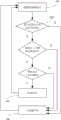
图1为现有技术中的一种电池充电电路的示意图。如图1中所示,现有技术中的电池充电电路通常包括:滤波电容C1和C2,并联在一蓄电池BR的两端,蓄电池BR的两端具有直流电压,即端电压UDC;由开关管Q1、Q2、Q3和Q4组成的逆变器/整流器,其直流端并联在蓄电池BR的两端;变压器T,其一侧绕组并联在该逆变器/整流器的交流端,另一侧绕组在AC市电正常时从AC市电汲取电能,在AC市电断电时为负载提供交流电;以及适当的接地。上述元件的具体连接关系如图1中所示。FIG. 1 is a schematic diagram of a battery charging circuit in the prior art. As shown in FIG. 1 , the battery charging circuit in the prior art generally includes: filter capacitors C1 and C2 , which are connected in parallel to both ends of a batteryBR , and both ends of the batteryBR have a DC voltage, that is, the terminal voltage UDC ; an inverter/rectifier composed of switching tubes Q1 , Q2 , Q3 and Q4 , whose DC terminals are connected in parallel with both ends of the batteryBR ; a transformer T whose one side winding is connected in parallel with the inverter/rectifier The AC end of the rectifier, the other side winding draws power from the AC mains when the AC mains is normal, and provides AC power for the load when the AC mains is out of power; and proper grounding. The specific connection relationship of the above elements is shown in FIG. 1 .
图1中所示的电池充电电路通常称为在线互动式UPS充电电路,其通过控制开关管Q3和Q4的导通时间来对蓄电池BR进行充电。The battery charging circuit shown in FIG. 1 is usually called an online interactive UPS charging circuit, which charges the batteryBR by controlling the on-time of the switching tubesQ3 andQ4 .
然而,图1中所示的传统在线互动式UPS充电电路存在如下缺点:However, the traditional online interactive UPS charging circuit shown in Figure 1 has the following disadvantages:
1、由于是通过固定占空比来控制开关管Q3和Q4进行恒压充电,所以充电初期电流过大,容易造成蓄电池BR的极板硫化。1. Since the switching tubesQ3 andQ4 are controlled by a fixed duty ratio for constant voltage charging, the current is too large in the initial stage of charging, which is likely to cause the vulcanization of the batteryBR plate.
2、由于UPS是在AC市电断电的情况下才投入工作,因此蓄电池BR不会处于完全充放电状态。这样,蓄电池BR长时间使用将导致极板内电解质难以分解,最终生成硫酸铅,增大了蓄电池BR的内阻。另外,传统的UPS充电方式无法根据蓄电池BR的内阻情况调整充电电压,无法对已经硫化的蓄电池BR进行去硫化处理。2. Since the UPS is only put into work when the AC mains is cut off, the batteryBR will not be in a fully charged and discharged state. In this way, if the batteryBR is used for a long time, it will be difficult to decompose the electrolyte in the electrode plate, and eventually lead sulfate will be generated, which will increase the internal resistance of the batteryBR . In addition, the traditional UPS charging method cannot adjust the charging voltage according to the internal resistance of the batteryBR , and cannot perform de-vulcanization treatment on the vulcanized batteryBR .
3、由于对于充电后期无浮充机制,或者一直保持浮充,而且UPS控制板电路电源由蓄电池BR提供,这样,如果蓄电池BR长时间处于不充电状态,将导致蓄电池BR过放电,或者,由于蓄电池BR一直处于浮充状态,将导致蓄电池BR过充电,从而使UPS整机效率下降或产生温升等问题。3. Since there is no floating charging mechanism in the later stage of charging, or floating charging is always maintained, and the circuit power supply of the UPS control board is provided by the batteryBR , if the batteryBR is not charged for a long time, it will cause the batteryBR to be over-discharged. Or, because the batteryBR is always in a floating charge state, the batteryBR will be overcharged, thereby reducing the efficiency of the UPS as a whole or causing problems such as temperature rise.
发明内容SUMMARY OF THE INVENTION
本发明的目的在于提供一种电池充电方法,以及使用该电池充电方法的电池充电系统,从而至少在一定程度上克服由于相关技术的限制和缺陷而导致的上述技术问题。The purpose of the present invention is to provide a battery charging method and a battery charging system using the battery charging method, so as to overcome the above-mentioned technical problems caused by the limitations and defects of the related art at least to a certain extent.
本发明的其它特性和优点将通过下面的详细描述变得显然,或部分地通过本发明的实践而习得。Other features and advantages of the present invention will become apparent from the following detailed description, or may be learned in part by practice of the present invention.
根据本发明的一个方面,提供一种电池充电方法,包括:检测一电池的端电压;当所述端电压小于一电压阈值时,执行一快速充电步骤,其中所述快速充电步骤包括:计算所述端电压的上升速率,将所述上升速率与一上升速率参考值进行比较,并根据比较结果控制所述端电压;以及当所述端电压不小于所述电压阈值时,执行一小电流浮充步骤,其中所述小电流浮充步骤包括:以一预定的浮充周期对所述电池进行间隔充电,在所述浮充周期的第一时间区间内,计算所述端电压的下降速率,将所述下降速率与一下降速率参考值进行比较,根据比较结果控制所述端电压,以及在所述浮充周期的第二时间区间内,中止充电。According to one aspect of the present invention, there is provided a battery charging method, comprising: detecting a terminal voltage of a battery; when the terminal voltage is less than a voltage threshold, performing a fast charging step, wherein the fast charging step includes: calculating the the rising rate of the terminal voltage, compare the rising rate with a rising rate reference value, and control the terminal voltage according to the comparison result; and when the terminal voltage is not less than the voltage threshold, perform a small current floating charging step, wherein the small-current floating charging step includes: charging the battery at intervals with a predetermined floating charging cycle, and calculating the drop rate of the terminal voltage in the first time interval of the floating charging cycle, The falling rate is compared with a falling rate reference value, the terminal voltage is controlled according to the comparison result, and charging is terminated during the second time interval of the floating charging period.
可选地,在所述快速充电步骤中,根据所述比较结果控制所述端电压包括:通过调节充电输入脉冲的占空比来控制所述端电压。Optionally, in the fast charging step, controlling the terminal voltage according to the comparison result includes: controlling the terminal voltage by adjusting the duty cycle of the charging input pulse.
可选地,在所述快速充电步骤中,当所述上升速率大于所述上升速率参考值,减小所述占空比,以及当所述上升速率小于所述上升速率参考值,增大所述占空比。Optionally, in the fast charging step, when the rise rate is greater than the rise rate reference value, the duty cycle is reduced, and when the rise rate is less than the rise rate reference value, the duty cycle is increased. the duty cycle.
可选地,在执行所述快速充电步骤前,如果经过一预定次数的调节,所述上升速率仍大于所述上升速率参考值,则跳转至所述小电流浮充步骤,并发出所述电池需要更换的告警。Optionally, before executing the fast charging step, if after a predetermined number of adjustments, the rise rate is still greater than the rise rate reference value, jump to the small current floating charge step, and issue the Alarm that the battery needs to be replaced.
可选地,在检测所述电池的端电压之前,预设所述占空比的初始值,并存储在非易失存储器中,其中,在所述快速充电步骤中,将调节后的所述占空比存储在所述非易失存储器中,作为所述占空比的更新的初始值。Optionally, before detecting the terminal voltage of the battery, the initial value of the duty cycle is preset and stored in a non-volatile memory, wherein, in the fast charging step, the adjusted The duty cycle is stored in the non-volatile memory as an updated initial value of the duty cycle.
可选地,在执行所述快速充电步骤前,将所述电池的电压变化范围分成多个电压区间,每一个所述端电压对应一个所述电压区间,以及每一个所述电压区间对应一个所述上升速率参考值。Optionally, before performing the fast charging step, the voltage variation range of the battery is divided into a plurality of voltage intervals, each of the terminal voltages corresponds to one of the voltage intervals, and each of the voltage intervals corresponds to one of the voltage intervals. The reference value of the rise rate mentioned above.
可选地,在所述小电流浮充步骤中,根据所述比较结果控制所述端电压包括:通过调节充电输入脉冲的占空比来控制所述端电压。Optionally, in the small current floating charging step, controlling the terminal voltage according to the comparison result includes: controlling the terminal voltage by adjusting the duty cycle of the charging input pulse.
可选地,在所述小电流浮充步骤中,当所述下降速率大于所述下降速率参考值,增大所述占空比,以及当所述下降速率小于所述下降速率参考值,减小所述占空比。Optionally, in the small current floating charging step, when the falling rate is greater than the falling rate reference value, the duty cycle is increased, and when the falling rate is less than the falling rate reference value, the duty cycle is decreased. smaller the duty cycle.
可选地,在检测所述电池的端电压之前,预设所述占空比的初始值,并存储在非易失存储器中,其中,在所述小电流浮充步骤中,将调节后的所述占空比存储在所述非易失存储器中,作为所述占空比的更新的初始值。Optionally, before detecting the terminal voltage of the battery, the initial value of the duty cycle is preset and stored in a non-volatile memory, wherein, in the small current floating charging step, the adjusted The duty cycle is stored in the non-volatile memory as an updated initial value of the duty cycle.
可选地,在执行所述小电流浮充步骤前,将所述电池的电压变化范围分成多个电压区间,每一个所述端电压对应一个所述电压区间,以及每一个所述电压区间对应一个所述下降速率参考值。Optionally, before performing the small current floating charging step, the voltage variation range of the battery is divided into a plurality of voltage intervals, each of the terminal voltages corresponds to one of the voltage intervals, and each of the voltage intervals corresponds to a plurality of voltage intervals. A reference value for the fall rate.
可选地,其中所述电池为铅酸电池。Optionally, the battery is a lead-acid battery.
可选地,所述电池充电方法还包括:在检测所述电池的端电压之前,由所述电池的电池特性得到所述上升率参考值和所述下降率参考值,并将所述上升率参考值和所述下降率参考值存储在非易失性存储器中。Optionally, the battery charging method further includes: before detecting the terminal voltage of the battery, obtaining the rise rate reference value and the fall rate reference value from the battery characteristics of the battery, and calculating the rise rate reference value. The reference value and the droop rate reference value are stored in non-volatile memory.
根据本发明的另一个方面,提供一种电池充电系统,包括:充电电路,被配置为包括一开关单元,其中所述开关单元耦接至一电池;检测电路,被配置为耦接至所述电池,以检测所述电池的端电压,并输出一反映所述端电压的采样信号;以及控制电路,被配置为接收所述采样信号,以输出一控制信号至所述充电电路,从而控制所述开关单元给所述电池充电,其中,当所述端电压小于一电压阈值时,执行一快速充电步骤,其中所述快速充电步骤包括:计算所述端电压的上升速率,将所述上升速率与一上升速率参考值进行比较,并根据比较结果来控制所述开关单元的导通时间,从而控制所述端电压,以及当所述端电压不小于所述电压阈值时,执行一小电流浮充步骤,其中所述小电流浮充步骤包括:以一预定的浮充周期对所述电池进行间隔充电,在所述浮充周期的第一时间区间内,计算所述端电压的下降速率,将所述下降速率与一下降速率参考值进行比较,根据比较结果来控制所述开关单元的导通时间,从而控制所述端电压,以及在所述浮充周期的第二时间区间内,使所述开关单元保持截止,从而中止充电。According to another aspect of the present invention, there is provided a battery charging system, comprising: a charging circuit configured to include a switch unit, wherein the switch unit is coupled to a battery; a detection circuit configured to be coupled to the a battery, to detect the terminal voltage of the battery, and output a sampling signal reflecting the terminal voltage; and a control circuit, configured to receive the sampling signal, to output a control signal to the charging circuit, so as to control the The switching unit charges the battery, wherein when the terminal voltage is less than a voltage threshold, a fast charging step is performed, wherein the fast charging step includes: calculating a rising rate of the terminal voltage, and calculating the rising rate Compare with a rising rate reference value, and control the on-time of the switch unit according to the comparison result, so as to control the terminal voltage, and when the terminal voltage is not less than the voltage threshold, perform a small current floating charging step, wherein the small-current floating charging step includes: charging the battery at intervals with a predetermined floating charging cycle, and calculating the drop rate of the terminal voltage in the first time interval of the floating charging cycle, The falling rate is compared with a falling rate reference value, and the on-time of the switch unit is controlled according to the comparison result, so as to control the terminal voltage, and in the second time interval of the floating charge cycle, make The switching unit remains off, thereby suspending charging.
可选地,在所述快速充电步骤中,根据比较结果来控制所述开关单元的导通时间,从而控制所述端电压包括:通过调节充电输入脉冲的占空比来控制所述端电压。Optionally, in the fast charging step, controlling the on-time of the switch unit according to the comparison result, so as to control the terminal voltage, includes: controlling the terminal voltage by adjusting the duty cycle of the charging input pulse.
可选地,在所述快速充电步骤中,当所述上升速率大于所述上升速率参考值,减小所述导通时间,以减小所述占空比,以及当所述上升速率小于所述上升速率参考值,增大所述导通时间,以增大所述占空比。Optionally, in the fast charging step, when the rise rate is greater than the rise rate reference value, the on-time is reduced to reduce the duty cycle, and when the rise rate is less than the rise rate The rise rate reference value is used to increase the on-time to increase the duty cycle.
可选地,在执行所述快速充电步骤前,如果经过一预定次数的调节,所述上升速率仍大于所述上升速率参考值,则跳转至所述小电流浮充步骤,并发出所述电池需要更换的告警。Optionally, before executing the fast charging step, if after a predetermined number of adjustments, the rise rate is still greater than the rise rate reference value, jump to the small current floating charge step, and issue the Alarm that the battery needs to be replaced.
可选地,在检测所述电池的端电压之前,预设所述导通时间的初始值,并存储在非易失存储器中,其中,在所述快速充电步骤中,将调节后的所述导通时间存储在所述非易失存储器中,作为所述导通时间的更新的初始值。Optionally, before detecting the terminal voltage of the battery, the initial value of the on-time is preset and stored in a non-volatile memory, wherein, in the fast charging step, the adjusted The on-time is stored in the non-volatile memory as an updated initial value of the on-time.
可选地,在执行所述快速充电步骤前,将所述电池的电压变化范围分成多个电压区间,每一个所述端电压对应一个所述电压区间,以及每一个所述电压区间对应一个所述上升速率参考值。Optionally, before performing the fast charging step, the voltage variation range of the battery is divided into a plurality of voltage intervals, each of the terminal voltages corresponds to one of the voltage intervals, and each of the voltage intervals corresponds to one of the voltage intervals. The reference value of the rise rate mentioned above.
可选地,在所述小电流浮充步骤中,根据比较结果来控制所述开关单元的导通时间,从而控制所述端电压包括:通过调节充电输入脉冲的占空比来控制所述端电压。Optionally, in the small current floating charging step, controlling the on-time of the switching unit according to the comparison result, so as to control the terminal voltage includes: controlling the terminal by adjusting the duty cycle of the charging input pulse. Voltage.
可选地,在所述小电流浮充步骤中,当所述下降速率大于所述下降速率参考值,增大所述导通时间,以增大所述占空比,以及当所述下降速率小于所述下降速率参考值,减小所述导通时间,以减小所述占空比。Optionally, in the small current floating charging step, when the falling rate is greater than the falling rate reference value, the on-time is increased to increase the duty cycle, and when the falling rate is Less than the fall rate reference value, the on-time is reduced to reduce the duty cycle.
可选地,在检测所述电池的端电压之前,预设所述导通时间的初始值,并存储在非易失存储器中,其中,在所述小电流浮充步骤中,将调节后的所述导通时间存储在所述非易失存储器中,作为所述导通时间的更新的初始值。Optionally, before detecting the terminal voltage of the battery, the initial value of the on-time is preset and stored in a non-volatile memory, wherein, in the small current floating charging step, the adjusted The on-time is stored in the nonvolatile memory as an updated initial value of the on-time.
可选地,在执行所述小电流浮充步骤前,将所述电池的电压变化范围分成多个电压区间,每一个所述端电压对应一个所述电压区间,以及每一个所述电压区间对应一个所述下降速率参考值。Optionally, before performing the small current floating charging step, the voltage variation range of the battery is divided into a plurality of voltage intervals, each of the terminal voltages corresponds to one of the voltage intervals, and each of the voltage intervals corresponds to a plurality of voltage intervals. A reference value for the fall rate.
可选地,其中所述电池为铅酸电池。Optionally, the battery is a lead-acid battery.
可选地,所述电池充电系统还包括:在检测所述电池的端电压之前,由所述电池的电池特性得到所述上升率参考值和所述下降率参考值,并将所述上升率参考值和所述下降率参考值存储在非易失性存储器中。Optionally, the battery charging system further includes: before detecting the terminal voltage of the battery, obtaining the rise rate reference value and the fall rate reference value from the battery characteristics of the battery, and calculating the rise rate reference value. The reference value and the droop rate reference value are stored in non-volatile memory.
本发明的电池充电方法以及使用该电池充电方法的电池充电系统只需要采样电池端电压即可控制充电电流,可以有效地提高电池充电效率、减少整机系统的损耗,有效保证电池充电量;不过充,可以延长电池的使用寿命;对于深度硫化的电池,可以起到去硫化的效果;对于故障电池,可以及时地提醒用户更换电池;特别是在小功率应用场合,由于电池充电效率的提高,可以选择容量较小的电池来满足系统放电时间上的要求。The battery charging method of the present invention and the battery charging system using the battery charging method only need to sample the battery terminal voltage to control the charging current, which can effectively improve the battery charging efficiency, reduce the loss of the whole system, and effectively ensure the battery charging capacity; however, It can prolong the service life of the battery; for the deeply vulcanized battery, it can have the effect of de-vulcanization; for the faulty battery, it can remind the user to replace the battery in time; especially in low-power applications, due to the improvement of the battery charging efficiency, A battery with a smaller capacity can be selected to meet the discharge time requirements of the system.
为使能更进一步了解本发明的特征及技术内容,请参阅以下有关本发明的详细说明与附图,但是这里的详细说明以及附图仅是用来说明本发明,而非对本发明的权利要求范围作任何的限制。In order to further understand the features and technical content of the present invention, please refer to the following detailed description and accompanying drawings of the present invention, but the detailed description and accompanying drawings here are only used to illustrate the present invention, rather than the claims of the present invention any limitation on the scope.
附图说明Description of drawings
通过参照附图详细描述其示例实施方式,本发明的上述和其它特征及优点将变得更加明显。The above and other features and advantages of the present invention will become more apparent from the detailed description of example embodiments thereof with reference to the accompanying drawings.
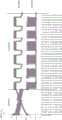
图1为现有技术中的一种电池充电电路的示意图;1 is a schematic diagram of a battery charging circuit in the prior art;
图2为本发明的一个实施例的电池充电方法的流程图;2 is a flowchart of a battery charging method according to an embodiment of the present invention;
图3为本发明的另一个实施例的电池充电方法的流程图;3 is a flowchart of a battery charging method according to another embodiment of the present invention;
图4为本发明的另一个实施例的电池充电方法的流程图;4 is a flowchart of a battery charging method according to another embodiment of the present invention;
图5为本发明的另一个实施例的电池充电方法的流程图;5 is a flowchart of a battery charging method according to another embodiment of the present invention;
图6为本发明的另一个实施例的电池充电方法的流程图;6 is a flowchart of a battery charging method according to another embodiment of the present invention;
图7为本发明的一个实施例的快速充电步骤的流程图;FIG. 7 is a flowchart of a quick charging step according to an embodiment of the present invention;
图8为本发明的一个实施例的小电流浮充步骤的流程图;FIG. 8 is a flowchart of a small current floating charging step according to an embodiment of the present invention;
图9为本发明的一个实施例的电池充电系统的示意图;以及FIG. 9 is a schematic diagram of a battery charging system according to an embodiment of the present invention; and
图10为本发明的一个实施例的充电曲线的示意图。FIG. 10 is a schematic diagram of a charging curve according to an embodiment of the present invention.
具体实施方式Detailed ways
现在将参考附图更全面地描述示例实施方式。然而,示例实施方式能够以多种形式实施,且不应被理解为限于在此阐述的实施方式;相反,提供这些实施方式使得本发明将全面和完整,并将示例实施方式的构思全面地传达给本领域的技术人员。在图中相同的附图标记表示相同或类似的结构,因而将省略它们的详细描述。Example embodiments will now be described more fully with reference to the accompanying drawings. Example embodiments, however, can be embodied in various forms and should not be construed as limited to the embodiments set forth herein; rather, these embodiments are provided so that this disclosure will be thorough and complete, and will fully convey the concept of example embodiments to those skilled in the art. The same reference numerals in the drawings denote the same or similar structures, and thus their detailed descriptions will be omitted.
此外,所描述的特征、结构或特性可以以任何合适的方式结合在一个或更多实施例中。在下面的描述中,提供许多具体细节从而给出对本发明的实施例的充分理解。然而,本领域技术人员将意识到,可以实践本发明的技术方案而没有所述特定细节中的一个或更多,或者可以采用其它的结构、部件、步骤、方法等。在其它情况下,不详细示出或描述公知结构、部件或者操作以避免模糊本发明的各方面。Furthermore, the described features, structures, or characteristics may be combined in any suitable manner in one or more embodiments. In the following description, numerous specific details are provided in order to give a thorough understanding of embodiments of the present invention. However, one skilled in the art will appreciate that the technical solutions of the present invention may be practiced without one or more of the specific details, or with other structures, components, steps, methods, etc., may be employed. In other instances, well-known structures, components, or operations are not shown or described in detail to avoid obscuring aspects of the present invention.
下面将结合图1-图10来描述本发明的电池充电方法,以及使用该电池充电方法的电池充电系统。The battery charging method of the present invention and a battery charging system using the battery charging method will be described below with reference to FIGS. 1 to 10 .
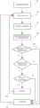
本发明的电池充电方法为一种在线互动式UPS充电控制方法,图2为本发明的一个实施例的电池充电方法的流程图。如图2中所示,本发明的电池充电方法包括:The battery charging method of the present invention is an online interactive UPS charging control method, and FIG. 2 is a flowchart of the battery charging method according to an embodiment of the present invention. As shown in Figure 2, the battery charging method of the present invention includes:
电压检测步骤100:检测如图1中所示的蓄电池BR的端电压UDC。Voltage detection step 100: Detect the terminal voltage UDC of the batteryBR as shown in FIG. 1 .
当端电压UDC小于一电压阈值UT时,例如小于14±0.2V时,或者说,当蓄电池BR的蓄电量未达到例如80%的电池容量时,执行一快速充电步骤200。在这里,“快速”可以是指,与充电后期相比,充电电流相对较大,蓄电池BR能够相对较快地获得电能。一定蓄电池BR的蓄电量与其端电压UDC具有相对固定的关系。When the terminal voltage UDC is less than a voltage thresholdUT , eg, less than 14±0.2V, or when the storage capacity of the batteryBR does not reach, eg, 80% of the battery capacity, a
快速充电步骤200:计算端电压UDC的上升速率PU,将上升速率PU与一上升速率参考值PUR进行比较,并根据比较结果控制端电压UDC。在这里,控制端电压UDC可理解为控制蓄电池BR的充电速度,从而控制端电压UDC的上升速率PU。Fast charging step 200: Calculate the rising rate PU of the terminal voltageUDC , compare the rising ratePU with a rising rate reference value PUR , and control the terminal voltage UDC according to the comparison result. Here, controlling the terminal voltage UDC can be understood as controlling the charging speed of the batteryBR , thereby controlling the rising rate PU of the terminal voltage UDC .
当端电压UDC不小于电压阈值UT时,例如不小于14±0.2V时,或者说,当蓄电池BR的蓄电量达到例如80%的电池容量时,执行一小电流浮充步骤300,在这里,“小”可以是指,与充电前期相比,充电电流相对较小,蓄电池BR获得电能的速度相对较慢。When the terminal voltage UDC is not less than the voltage threshold UT , for example, not less than 14±0.2V, or, in other words, when the storage capacity of the batteryBR reaches, for example, 80% of the battery capacity, a small current
小电流浮充步骤300:以一预定的浮充周期T对蓄电池BR进行间隔充电,在浮充周期T的第一时间区间T1内,计算端电压UDC的下降速率PD,将下降速率PD与一下降速率参考值PDR进行比较,根据比较结果控制端电压UDC,以及在浮充周期T的第二时间区间T2内,中止充电。在这里,一个“浮充周期”T可以包括一个第一时间区间T1和一个第二时间区间T2,第一时间区间T1与第二时间区间T2交替出现,直到蓄电池BR充满为止。在这里,控制端电压UDC可理解为控制蓄电池BR的充电速度,从而控制端电压UDC的下降速率PD。Small current float charging step 300 : charge the batteryBR at intervals with a predetermined float charging period T, and within thefirst time interval T1 of the floating charging period T, calculate the falling rate PD of the terminal voltage UDC , which will decrease The rate PD is compared with a falling rate reference value PDR , and the terminal voltage UDC is controlled according to the comparison result, and the charging is stopped during the second time interval T2 of the floating charging period T. Here, a "floating charge cycle" T may include a first time interval T1 and a second time interval T2 , the first time interval T1 and the second time interval T2 appear alternately until the batteryBR is fully charged . Here, controlling the terminal voltage UDC can be understood as controlling the charging speed of the batteryBR , thereby controlling the falling rate PD of the terminal voltage UDC .
作为一个实施例,在步骤100和步骤200之间,还包括判断步骤1001:判断蓄电池BR是否已进入了小电流浮充阶段。换句话说,就是:如果在正常的充电过程中,已经执行过了一次步骤300,则在执行步骤100后就仍然直接跳转至步骤300,不再执行步骤200,除非该电池充电系统重启。As an embodiment, between
作为一个实施例,在快速充电步骤200中,根据比较结果控制端电压UDC包括:通过调节充电输入脉冲的占空比来控制端电压UDC。在这里,“充电输入脉冲”可以是指,例如由如图1中所示的开关管Q1、Q2、Q3和Q4组成的逆变器/整流器作为整流器使用时,向蓄电池BR输入的电压脉冲。As an embodiment, in the
作为一个实施例,在快速充电步骤200中,当上升速率PU大于上升速率参考值PUR时,减小充电输入脉冲的占空比,从而减小充电电流,降低蓄电池BR的充电速度;当上升速率PU小于上升速率参考值PUR时,增大充电输入脉冲的占空比,从而增加充电电流,加快蓄电池BR的充电速度。As an embodiment, in the
图3为本发明的另一个实施例的电池充电方法的流程图。如图3中所示,作为一个实施例,在执行快速充电步骤200前,如果经过一预定次数的调节,端电压UDC的上升速率PU仍大于上升速率参考值PUR,即端电压上升速率过快多次,说明此时的蓄电池BR已经损坏,则跳转至小电流浮充步骤300,并发出蓄电池BR需要更换的告警。FIG. 3 is a flowchart of a battery charging method according to another embodiment of the present invention. As shown in FIG. 3 , as an embodiment, before performing the
图4为本发明的另一个实施例的电池充电方法的流程图。如图4中所示,作为一个实施例,在检测蓄电池BR的端电压UDC的步骤100之前,还包括预设步骤90:预设占空比的初始值,并存储在非易失存储器中。在这里,非易失存储器可以是例如EPROM和Flash等。FIG. 4 is a flowchart of a battery charging method according to another embodiment of the present invention. As shown in FIG. 4 , as an embodiment, before the
在快速充电步骤200中,可以将调节后的占空比存储在非易失存储器中,作为占空比的更新的初始值,以便充电设备在下次开机后使用。In the
在本发明的另一个实施例中,当电池的充电电路包含如图1中的开关管Q1、Q2、Q3和Q4组成的开关单元时,可通过增大开关单元的相应导通时间,增大充电输入脉冲的占空比,或者通过减小开关单元的相应导通时间,减小充电输入脉冲的占空比,因此,对应地,在检测蓄电池BR的端电压UDC的步骤100之前,还可以预设开关单元的相应导通时间的初始值,并存储在非易失存储器中,在快速充电步骤200中,可将调节后的导通时间存储在非易失存储器中,作为导通时间的更新的初始值。In another embodiment of the present invention, when the charging circuit of the battery includes a switch unit composed of switch tubes Q1 , Q2 , Q3 and Q4 as shown in FIG. 1 , the corresponding conduction of the switch unit can be increased by increasing time, increase the duty cycle of the charging input pulse, or reduce the duty cycle of the charging input pulse by reducing the corresponding conduction time of the switch unit. Therefore, correspondingly, when detecting the terminal voltage UDC of the batteryBR Before
图5为本发明的另一个实施例的电池充电方法的流程图。如图5中所示,作为一个实施例,在执行快速充电步骤200前,还包括步骤80:将蓄电池BR的电压变化范围分成多个电压区间,每一个端电压UDC归属于一个电压区间,即对应一个电压区间,以及每一个电压区间对应一个上升速率参考值PUR。在这里,“电压变化范围”可以是指蓄电池BR的正常电池电压范围,也就是蓄电池BR允许使用的电压范围,例如对于12V的铅酸电池来说,其电压变化范围为9.8V~14V。根据控制的精细程度,一个电压区间可以为例如0.5V、0.2V、0.1V等各种数值。FIG. 5 is a flowchart of a battery charging method according to another embodiment of the present invention. As shown in FIG. 5 , as an embodiment, before executing the
与前述的快速充电步骤200中控制端电压UDC的方式相同,作为一个实施例,在小电流浮充步骤300中,根据比较结果控制端电压UDC也包括:通过调节充电输入脉冲的占空比来控制端电压UDC。In the same manner as the control terminal voltage UDC in the aforementioned
与前述的快速充电步骤200中控制端电压UDC的方式类似,作为一个实施例,在小电流浮充步骤300中,当下降速率PD大于下降速率参考值PDR时,增大充电输入脉冲的占空比,从而加快蓄电池BR的充电速度;当下降速率PD小于下降速率参考值PDR时,减小充电输入脉冲的占空比,从而降低蓄电池BR的充电速度。Similar to the method of controlling the terminal voltage UDC in the aforementioned
仍如前述图4中所示,作为一个实施例,在检测蓄电池BR的端电压UDC的步骤100之前,还包括预设步骤90:预设占空比的初始值,并存储在非易失存储器中。在这里,非易失存储器可以是例如EPROM和Flash等。Still as shown in the aforementioned FIG. 4 , as an embodiment, before the
在小电流浮充步骤300中,可以将调节后的占空比存储在非易失存储器中,作为占空比的更新的初始值,以便充电设备在下次开机后使用。In the small current floating charging
在本发明的另一个实施例中,当电池的充电电路包含开关单元时,可通过增大开关单元的相应导通时间,增大充电输入脉冲的占空比,或者通过减小开关单元的相应导通时间,减小充电输入脉冲的占空比,因此,对应地,在检测蓄电池BR的端电压UDC的步骤100之前,还可以预设开关单元的相应导通时间的初始值,并存储在非易失存储器中,在小电流浮充步骤300中,可将调节后的导通时间存储在非易失存储器中,作为导通时间的更新的初始值。In another embodiment of the present invention, when the charging circuit of the battery includes a switch unit, the duty cycle of the charging input pulse can be increased by increasing the corresponding on-time of the switch unit, or by reducing the corresponding turn-on time of the switch unit. The turn-on time reduces the duty cycle of the charging input pulse. Therefore, correspondingly, before
仍如前述图5中所示,作为一个实施例,在执行小电流浮充步骤300前,还包括划分步骤80:将蓄电池BR的电压变化范围分成多个电压区间,每一个端电压UDC归属于一个电压区间,即对应一个电压区间,以及每一个电压区间对应一个下降速率参考值PDR。在这里,“电压变化范围”可以是指蓄电池BR的正常电池电压范围,也就是允许使用的电压范围,例如对于12V的铅酸电池来说,其电压变化范围为9.8V~14V。根据控制的精细程度,一个电压区间可以为例如0.5V、0.2V、0.1V等各种数值。Still as shown in the aforementioned FIG. 5 , as an embodiment, before the small current floating charging
作为一个实施例,快速充电步骤200中使用的电压区间可以不同于小电流浮充步骤300中使用的电压区间。As an example, the voltage interval used in the
作为一个实施例,前述的蓄电池BR可以为铅酸电池,简称电池。As an embodiment, the aforementioned batteryBR may be a lead-acid battery, or battery for short.
作为一个实施例,在检测蓄电池BR的端电压UDC之前,可以由蓄电池BR的电池特性得到上升率参考值PUR和下降率参考值PDR,并将上升率参考值PUR和下降率参考值PDR存储在非易失性存储器中。在这里,蓄电池BR的“电池特性”可以是指生产蓄电池BR的厂商提供的蓄电池BR的理论充放电曲线。As an example, before the terminal voltage UDC of the batteryBR is detected, the rise rate reference value P UR and the drop rate reference value P DR can be obtained from the battery characteristics of the batteryBR , and the rise rate reference value PUR and the drop rate reference value PDR can be obtained from the battery characteristics of the batteryBR . The rate reference valuePDR is stored in non-volatile memory. Here, the "battery characteristics" of the batteryBR may refer to the theoretical charge-discharge curve of the batteryBR provided by the manufacturer of the batteryBR .
图6为本发明的另一个实施例的电池充电方法的流程图,用于更全面地理解本发明。如图6中所示,本发明的电池充电方法包括:FIG. 6 is a flowchart of a battery charging method according to another embodiment of the present invention, for a more comprehensive understanding of the present invention. As shown in Figure 6, the battery charging method of the present invention includes:
如前所述的划分步骤80:将蓄电池BR的电压变化范围分成多个电压区间。这里不再赘述。The
如前所述的步骤100,检测如图1中所示的蓄电池BR的端电压UDC。这里不再赘述。As in the
步骤110:确定端电压UDC所属的电压区间。如前所述,每一个端电压UDC归属于一个电压区间,即对应一个电压区间。Step 110: Determine the voltage range to which the terminal voltage UDC belongs. As mentioned above, each terminal voltage UDC belongs to a voltage interval, that is, corresponds to a voltage interval.
步骤120:确定当前区间端电压上升速率参考值或下降速率参考值(分别对应于快速充电阶段和小电流浮冲阶段)。如前所述,每一个电压区间对应一个上升速率参考值PUR或下降速率参考值PDR。Step 120 : Determine the reference value of the rising rate or the reference value of the falling rate of the current interval terminal voltage (corresponding to the fast charging stage and the small current floating stage, respectively). As mentioned above, each voltage interval corresponds to a rising rate reference value PUR or a falling rate reference value PDR .
如前所述的判断步骤1001:判断蓄电池BR是否已进入了小电流浮充阶段。这里不再赘述。
通过判断端电压UDC的上升速率PU过快(过大)是否已经连续发生多次,来确定是否有必要继续进行下面的快速充电步骤200。It is determined whether it is necessary to continue the following fast charging
通过判断端电压UDC是否小于电压阈值UT,或者说,是否蓄电池BR的蓄电量达到例如80%的电池容量,来确定是否需要结束快速充电步骤200并进入小电流浮冲步骤300。By judging whether the terminal voltage UDC is less than the voltage threshold UT , or whether the storage capacity of the batteryBR reaches, for example, 80% of the battery capacity, it is determined whether it is necessary to end the
如前所述的快速充电步骤200。这里不再赘述。Fast charging
如前所述的小电流浮冲步骤300。这里不再赘述。The small current floating
各步骤的逻辑关系如图6中所示。The logical relationship of each step is shown in FIG. 6 .
图7为本发明的一个实施例的快速充电步骤200的流程图,用于更全面地理解本发明。如图7中所示,本发明的快速充电步骤200包括:FIG. 7 is a flowchart of a
步骤210:从存储器读取所属电压区间的充电输入脉冲的占空比。Step 210: Read the duty cycle of the charging input pulse in the voltage interval to which it belongs from the memory.
步骤220:使用所检测的电压UDC,来计算端电压UDC的上升速率PU。Step 220: Use the detected voltage UDC to calculate the rising rate PU of the terminal voltage UDC .
步骤230:将端电压UDC的上升速率PU与当前电压区间的端电压上升速率参考值PUR进行比较。Step 230: Compare the rising rate PU of the terminal voltage UDC with the terminal voltage rising rate reference value PUR in the current voltage interval.
步骤240:根据比较结果调节充电输入脉冲的占空比。Step 240: Adjust the duty cycle of the charging input pulse according to the comparison result.
步骤250:将调节后的充电输入脉冲的占空比存入存储器,作为当前电压区间对应的占空比的更新的初始值,以便充电设备在下次开机后使用。Step 250: Store the adjusted duty cycle of the charging input pulse in the memory as an updated initial value of the duty cycle corresponding to the current voltage interval, so that the charging device can be used after the next power-on.
图8为本发明的一个实施例的小电流浮充步骤300的流程图,用于更全面地理解本发明。如图8中所示,本发明的小电流浮充步骤300包括:FIG. 8 is a flowchart of a small current
步骤310:从存储器读取所属电压区间的充电输入脉冲的占空比。Step 310: Read the duty cycle of the charging input pulse in the voltage interval to which it belongs from the memory.
步骤320:使用所检测的电压UDC,来计算端电压UDC的下降速率PD。Step 320: Use the detected voltage UDC to calculate the falling ratePD of the terminal voltage UDC .
步骤330:将端电压UDC的下降速率PD与当前电压区间的端电压下降速率参考值PDR进行比较。Step 330: Compare the falling ratePD of the terminal voltage UDC with the terminal voltage falling rate reference value PDR in the current voltage interval.
步骤340:根据比较结果调节充电输入脉冲的占空比。Step 340: Adjust the duty cycle of the charging input pulse according to the comparison result.
步骤350:将调节后的充电输入脉冲的占空比存入存储器,作为当前电压区间对应的占空比的更新的初始值,以便充电设备在下次开机后使用。Step 350: Store the adjusted duty cycle of the charging input pulse in the memory as an updated initial value of the duty cycle corresponding to the current voltage interval, so that the charging device can be used after the next power-on.
如前所述,由于本发明的小电流浮充步骤300是以一预定的浮充周期T对蓄电池BR进行间隔充电,一个“浮充周期”T仅充电第一时间区间T1,因此在步骤350之后计时第一时间区间T1的时间长度,然后进行下面的步骤360。作为一个实施例,在进行下面的步骤360之前,还可以还返回到前面的检测步骤100,以便更精细地调节充电速率。As mentioned above, since the low-current floating charging
步骤360:中止充电第二时间长度T2。在计时第二时间区间T2的时间长度后,返回到前面的检测步骤100。Step 360: Suspend charging for the second time length T2 . After counting the time length of the second time interval T2 , return to the
以上结合图1-图8描述了本发明的电池充电方法。The battery charging method of the present invention is described above with reference to FIGS. 1 to 8 .
本发明还提供了一种使用如前述结合图1-图8所描述的电池充电方法的电池充电系统。The present invention also provides a battery charging system using the battery charging method described above in conjunction with FIGS. 1-8 .
图9为本发明的一个实施例的电池充电系统的示意图。如图9中所示,本发明的电池充电系统,包括:FIG. 9 is a schematic diagram of a battery charging system according to an embodiment of the present invention. As shown in FIG. 9, the battery charging system of the present invention includes:
例如如图1所示的充电电路,被配置为包括一开关单元,例如由开关管Q1、Q2、Q3和Q4组成的逆变器/整流器,其中所述开关单元耦接至一电池,例如蓄电池BR。本发明不限于如图1所示的充电电路。For example, the charging circuit shown in FIG. 1 is configured to include a switch unit, such as an inverter/rectifier composed of switch transistors Q1 , Q2 , Q3 and Q4 , wherein the switch unit is coupled to a Batteries, such as accumulatorsBR . The present invention is not limited to the charging circuit shown in FIG. 1 .
检测电路2,被配置为耦接至例如蓄电池BR,以检测蓄电池BR的端电压UDC,并输出一反映端电压UDC的采样信号SS。The detection circuit 2 is configured to be coupled to, for example, the batteryBR to detect the terminal voltage UDC of the batteryBR and output a sampling signal SS reflecting the terminal voltage UDC .
控制电路3,被配置为接收采样信号SS,以输出一控制信号SC至所述充电电路,从而控制所述开关单元给蓄电池BR充电。The control circuit 3 is configured to receive the sampling signal SS to output a control signal SC to the charging circuit, so as to control the switching unit to charge the batteryBR .
当端电压UDC小于一电压阈值UT时,执行前述的快速充电步骤200,其中快速充电步骤200包括:计算端电压UDC的上升速率PU,将上升速率PU与一上升速率参考值PUR进行比较,并根据比较结果来控制所述开关单元的导通时间,从而控制端电压UDC。When the terminal voltage UDC is less than a voltage thresholdUT , the aforementioned
当端电压UDC不小于电压阈值UT时,或者说,当蓄电池BR的蓄电量达到例如80%的电池容量时,执行前述的小电流浮充步骤300,其中小电流浮充步骤300包括:以一预定的浮充周期T对蓄电池BR进行间隔充电,在浮充周期T的第一时间区间T1内,计算端电压UDC的下降速率PD,将下降速率PD与一下降速率参考值PDR进行比较,根据比较结果来控制所述开关单元的导通时间,从而控制端电压UDC,以及在浮充周期T的第二时间区间T2内,使所述开关单元保持截止,从而中止充电。When the terminal voltage UDC is not less than the voltage thresholdUT , or in other words, when the storage capacity of the batteryBR reaches, for example, 80% of the battery capacity, the aforementioned low-current floating charging
作为一个实施例,在快速充电步骤200中,根据比较结果来控制所述开关单元的导通时间,从而控制端电压UDC,包括:通过调节充电输入脉冲的占空比来控制端电压UDC。As an embodiment, in the
作为一个实施例,在快速充电步骤200中,当上升速率PU大于上升速率参考值PUR,减小开关单元的导通时间,以减小充电输入脉冲的占空比,以及当上升速率PU小于上升速率参考值PUR,增大开关单元的导通时间,以增大充电输入脉冲的占空比。As an example, in the
作为一个实施例,在执行快速充电步骤200前,如果经过一预定次数的调节,上升速率PU仍大于上升速率参考值PUR,则跳转至小电流浮充步骤300,并发出蓄电池BR需要更换的告警。As an example, before executing the
作为一个实施例,在检测蓄电池BR的端电压UDC之前,预设开关单元的导通时间的初始值,并存储在非易失存储器中,其中,在快速充电步骤200中,将调节后的导通时间存储在非易失存储器中,作为导通时间的更新的初始值。As an embodiment, before the terminal voltage UDC of the batteryBR is detected, the initial value of the on-time of the switch unit is preset and stored in the non-volatile memory, wherein, in the
作为一个实施例,在执行快速充电步骤200前,将蓄电池BR的电压变化范围分成多个电压区间,每一个端电压UDC归属于一个电压区间,即对应一个电压区间,以及每一个电压区间对应一个上升速率参考值PUR。As an embodiment, before the
作为一个实施例,在小电流浮充步骤300中,根据比较结果来控制所述开关单元的导通时间,从而控制端电压UDC包括:通过调节充电输入脉冲的占空比来控制端电压UDC。As an embodiment, in the low-current floating charging
作为一个实施例,在小电流浮充步骤300中,当下降速率PD大于下降速率参考值PDR,增大开关单元的导通时间,以增大充电输入脉冲的占空比,以及当下降速率PD小于下降速率参考值PDR,减小开关单元的导通时间,以减小充电输入脉冲的占空比。As an example, in the small current floating charging
作为一个实施例,在步骤100和步骤200之间,还包括判断步骤1001:判断蓄电池BR是否已进入了小电流浮充阶段。换句话说,就是:如果在正常的充电过程中,已经执行过了一次步骤300,则在执行步骤100后就仍然直接跳转至步骤300,不再执行步骤200,除非该电池充电系统重启。As an embodiment, between
作为一个实施例,在检测蓄电池BR的端电压UDC之前,预设开关单元的导通时间的初始值,并存储在非易失存储器中,其中,在小电流浮充步骤300中,将调节后的导通时间存储在非易失存储器中,作为导通时间的更新的初始值。As an embodiment, before the terminal voltage UDC of the batteryBR is detected, the initial value of the on-time of the switch unit is preset and stored in the non-volatile memory, wherein, in the small current
作为一个实施例,在执行小电流浮充步骤300前,将蓄电池BR的电压变化范围分成多个电压区间,每一个端电压UDC归属于一个电压区间,即对应一个电压区间,以及每一个电压区间对应一个下降速率参考值PDR。As an embodiment, before the small current floating
作为一个实施例,这里的蓄电池BR可以为铅酸电池,简称电池。As an embodiment, the batteryBR here may be a lead-acid battery, or battery for short.
作为一个实施例,在检测蓄电池BR的端电压UDC之前,由蓄电池BR的电池特性得到上升率参考值PUR和下降率参考值PDR,并将上升率参考值PUR和下降率参考值PDR存储在非易失性存储器中。As an example, before the terminal voltage UDC of the batteryBR is detected, the reference value of the rise rate PUR and the reference value of the drop rate PDR are obtained from the battery characteristics of the batteryBR , and the reference value of the rise rate PUR and the reference value of the drop rate are obtained. The reference valuePDR is stored in non-volatile memory.
当采用图9所示的充电电路时,图10为本发明的一个实施例的充电曲线的示意图,示出了充电过程中的电压曲线和电流曲线,用于更全面地理解本发明。如图10中所示:When the charging circuit shown in FIG. 9 is used, FIG. 10 is a schematic diagram of the charging curve of an embodiment of the present invention, showing the voltage curve and the current curve during the charging process, for a more comprehensive understanding of the present invention. As shown in Figure 10:
在快速充电阶段,蓄电池BR的端电压UDC从大约12.2V开始上升,对应的充电电流相对较大。充电电流逐渐下降。In the fast charging stage, the terminal voltage UDC of the batteryBR starts to rise from about 12.2V, and the corresponding charging current is relatively large. The charging current gradually decreases.
在蓄电池BR的端电压UDC上升到大约13.8V时,即电压阈值UT,开始进入小电流浮充阶段。在小电流浮充阶段,可以根据UPS整机系统温升情况,设定浮充周期,以及第一时间区间和第二时间区间,例如:以3小时的浮充周期T对蓄电池BR进行间隔充电,在2小时的第一时间区间T1内,对蓄电池BR进行小电流充电,在1小时的第二时间区间T2内,中止充电。在本实施例的小电流浮充阶段,当蓄电池同时还需要向UPS系统中的控制电路等供电时,并且蓄电池本身就存在自放电损耗,蓄电池BR的端电压UDC有所下降,甚至降低至小于电压阈值UT,但本发明的充电方法会保证其稳定在小电流浮充阶段,除非重新开机。When the terminal voltage UDC of the batteryBR rises to about 13.8V, that is, the voltage threshold UT , it begins to enter the low-current floating charge stage. In the low-current floating charging stage, the floating charging cycle, the first time interval and the second time interval can be set according to the temperature rise of the UPS system. For charging, in the first time interval T1 of2 hours, the batteryBR is charged with a small current, and in the second time interval T2 of1 hour, the charging is stopped. In the low-current floating charging stage of this embodiment, when the battery also needs to supply power to the control circuit in the UPS system, and the battery itself has self-discharge loss, the terminal voltage UDC of the batteryBR decreases, or even decreases to less than the voltage thresholdUT , but the charging method of the present invention will ensure that it is stable in the low current floating charging stage unless it is restarted.
本发明的电池充电方法以及使用该电池充电方法的电池充电系统只需要采样电池端电压即可控制充电电流,可以有效地提高电池充电效率、减少整机系统的损耗,有效保证电池充电量;不过充,可以延长电池的使用寿命;对于深度硫化的电池,可以起到去硫化的效果;对于故障电池,可以及时地提醒用户更换电池;特别是在小功率应用场合,由于电池充电效率的提高,可以选择容量较小的电池来满足系统放电时间上的要求。The battery charging method of the present invention and the battery charging system using the battery charging method only need to sample the battery terminal voltage to control the charging current, which can effectively improve the battery charging efficiency, reduce the loss of the whole system, and effectively ensure the battery charging capacity; however, It can prolong the service life of the battery; for the deeply vulcanized battery, it can have the effect of de-vulcanization; for the faulty battery, it can remind the user to replace the battery in time; especially in low-power applications, due to the improvement of the battery charging efficiency, A battery with a smaller capacity can be selected to meet the discharge time requirements of the system.
本发明已由上述相关实施例加以描述,然而上述实施例仅为实施本发明的范例。必需指出的是,已揭露的实施例并未限制本发明的范围。相反地,在不脱离本发明的精神和范围内所作的更动与润饰,均属本发明的专利保护范围。The present invention has been described by the above-mentioned related embodiments, however, the above-mentioned embodiments are only examples for implementing the present invention. It must be pointed out that the disclosed embodiments do not limit the scope of the present invention. On the contrary, changes and modifications made without departing from the spirit and scope of the present invention belong to the scope of patent protection of the present invention.
Claims (24)
Priority Applications (2)
| Application Number | Priority Date | Filing Date | Title |
|---|---|---|---|
| CN201810917944.3ACN110828913B (en) | 2018-08-13 | 2018-08-13 | Battery charging method and charging system thereof |
| US16/532,583US11190039B2 (en) | 2018-08-13 | 2019-08-06 | Method of charging battery and system using the same |
Applications Claiming Priority (1)
| Application Number | Priority Date | Filing Date | Title |
|---|---|---|---|
| CN201810917944.3ACN110828913B (en) | 2018-08-13 | 2018-08-13 | Battery charging method and charging system thereof |
Publications (2)
| Publication Number | Publication Date |
|---|---|
| CN110828913Atrue CN110828913A (en) | 2020-02-21 |
| CN110828913B CN110828913B (en) | 2023-01-20 |
Family
ID=69405098
Family Applications (1)
| Application Number | Title | Priority Date | Filing Date |
|---|---|---|---|
| CN201810917944.3AActiveCN110828913B (en) | 2018-08-13 | 2018-08-13 | Battery charging method and charging system thereof |
Country Status (2)
| Country | Link |
|---|---|
| US (1) | US11190039B2 (en) |
| CN (1) | CN110828913B (en) |
Cited By (3)
| Publication number | Priority date | Publication date | Assignee | Title |
|---|---|---|---|---|
| CN112564228A (en)* | 2020-12-11 | 2021-03-26 | 清远道动新材料科技有限公司 | UPS power supply |
| CN113991195A (en)* | 2020-05-19 | 2022-01-28 | 杭州铅锂智行科技有限公司 | Charger and charging method thereof |
| CN114336909A (en)* | 2022-02-14 | 2022-04-12 | 宁波古得电子科技有限公司 | Battery charging method |
Families Citing this family (3)
| Publication number | Priority date | Publication date | Assignee | Title |
|---|---|---|---|---|
| SE544381C2 (en)* | 2020-04-09 | 2022-04-26 | Ctek Sweden Ab | Method for improving life span of a battery |
| CN114430182A (en)* | 2020-10-29 | 2022-05-03 | 微盟电子(昆山)有限公司 | Charge and discharge control method and device, electronic equipment and computer readable storage medium |
| CN117081194A (en)* | 2023-08-03 | 2023-11-17 | 漳州科华电气技术有限公司 | Charging control method of battery system and battery system |
Citations (16)
| Publication number | Priority date | Publication date | Assignee | Title |
|---|---|---|---|---|
| US5691620A (en)* | 1993-09-17 | 1997-11-25 | Sony Corporation | Battery charging method |
| US6259231B1 (en)* | 2000-11-16 | 2001-07-10 | R G Technology Ventures, Llc | Rapid battery charger |
| JP2004274849A (en)* | 2003-03-06 | 2004-09-30 | Sony Corp | Method and device for charging battery |
| CN1897402A (en)* | 2005-07-11 | 2007-01-17 | 李建国 | High-speed multi-stage charging system and method for self-adaptive tractive dynamic battery |
| US20090160407A1 (en)* | 2007-12-24 | 2009-06-25 | Hwang Ho Chul | Charger Capable of Performing Integrated Control and Separate Control of Parallel Operations |
| CN101682197A (en)* | 2007-03-26 | 2010-03-24 | 吉列公司 | Adaptive charger device and method |
| CN101702453A (en)* | 2009-10-27 | 2010-05-05 | 中兴通讯股份有限公司 | Battery charging management method and device |
| CN102082458A (en)* | 2010-12-31 | 2011-06-01 | 易事特电力系统技术有限公司 | Inverter intelligent charging control method |
| CN102136614A (en)* | 2011-02-18 | 2011-07-27 | 江苏技术师范学院 | Self-adapting charging method for valve-regulated lead-acid storage battery |
| JP2012151994A (en)* | 2011-01-19 | 2012-08-09 | Konica Minolta Medical & Graphic Inc | Charger and radiation image detection system |
| CN104467077A (en)* | 2014-11-14 | 2015-03-25 | 合肥正美电源科技有限公司 | Storage battery charging control method |
| SE1550312A1 (en)* | 2015-03-16 | 2016-09-17 | Ctek Sweden Ab | A method for operating a battery charger, and a battery charger |
| CN106877473A (en)* | 2017-04-17 | 2017-06-20 | 徐向伦 | Lead-acid accumulator control method for quickly charging, Variable flow control circuit and quick charge device |
| JP2017195681A (en)* | 2016-04-19 | 2017-10-26 | 三菱自動車エンジニアリング株式会社 | Battery capacity measuring device and battery capacity measuring program |
| KR20180002033A (en)* | 2016-06-28 | 2018-01-05 | 주식회사 마루온 | Monitoring System For Battery Of Base Transceiver Station Tower |
| GB201720359D0 (en)* | 2017-12-06 | 2018-01-17 | Oxis Energy Ltd | Battery management |
Family Cites Families (4)
| Publication number | Priority date | Publication date | Assignee | Title |
|---|---|---|---|---|
| US7586214B2 (en)* | 2006-10-11 | 2009-09-08 | Gm Global Technology Operations, Inc. | High voltage energy storage connection monitoring system and method |
| CN105480106B (en) | 2015-11-20 | 2017-09-29 | 浙江超威创元实业有限公司 | Electric automobile lithium battery managing device and control method |
| US11243260B2 (en)* | 2017-07-28 | 2022-02-08 | Northstar Battery Company, Llc | Systems and methods for determining an operating mode of a battery |
| CN110417094A (en)* | 2019-08-06 | 2019-11-05 | 深圳市瀚强科技股份有限公司 | A kind of method for charging batteries and charging equipment |
- 2018
- 2018-08-13CNCN201810917944.3Apatent/CN110828913B/enactiveActive
- 2019
- 2019-08-06USUS16/532,583patent/US11190039B2/enactiveActive
Patent Citations (16)
| Publication number | Priority date | Publication date | Assignee | Title |
|---|---|---|---|---|
| US5691620A (en)* | 1993-09-17 | 1997-11-25 | Sony Corporation | Battery charging method |
| US6259231B1 (en)* | 2000-11-16 | 2001-07-10 | R G Technology Ventures, Llc | Rapid battery charger |
| JP2004274849A (en)* | 2003-03-06 | 2004-09-30 | Sony Corp | Method and device for charging battery |
| CN1897402A (en)* | 2005-07-11 | 2007-01-17 | 李建国 | High-speed multi-stage charging system and method for self-adaptive tractive dynamic battery |
| CN101682197A (en)* | 2007-03-26 | 2010-03-24 | 吉列公司 | Adaptive charger device and method |
| US20090160407A1 (en)* | 2007-12-24 | 2009-06-25 | Hwang Ho Chul | Charger Capable of Performing Integrated Control and Separate Control of Parallel Operations |
| CN101702453A (en)* | 2009-10-27 | 2010-05-05 | 中兴通讯股份有限公司 | Battery charging management method and device |
| CN102082458A (en)* | 2010-12-31 | 2011-06-01 | 易事特电力系统技术有限公司 | Inverter intelligent charging control method |
| JP2012151994A (en)* | 2011-01-19 | 2012-08-09 | Konica Minolta Medical & Graphic Inc | Charger and radiation image detection system |
| CN102136614A (en)* | 2011-02-18 | 2011-07-27 | 江苏技术师范学院 | Self-adapting charging method for valve-regulated lead-acid storage battery |
| CN104467077A (en)* | 2014-11-14 | 2015-03-25 | 合肥正美电源科技有限公司 | Storage battery charging control method |
| SE1550312A1 (en)* | 2015-03-16 | 2016-09-17 | Ctek Sweden Ab | A method for operating a battery charger, and a battery charger |
| JP2017195681A (en)* | 2016-04-19 | 2017-10-26 | 三菱自動車エンジニアリング株式会社 | Battery capacity measuring device and battery capacity measuring program |
| KR20180002033A (en)* | 2016-06-28 | 2018-01-05 | 주식회사 마루온 | Monitoring System For Battery Of Base Transceiver Station Tower |
| CN106877473A (en)* | 2017-04-17 | 2017-06-20 | 徐向伦 | Lead-acid accumulator control method for quickly charging, Variable flow control circuit and quick charge device |
| GB201720359D0 (en)* | 2017-12-06 | 2018-01-17 | Oxis Energy Ltd | Battery management |
Cited By (4)
| Publication number | Priority date | Publication date | Assignee | Title |
|---|---|---|---|---|
| CN113991195A (en)* | 2020-05-19 | 2022-01-28 | 杭州铅锂智行科技有限公司 | Charger and charging method thereof |
| CN112564228A (en)* | 2020-12-11 | 2021-03-26 | 清远道动新材料科技有限公司 | UPS power supply |
| CN112564228B (en)* | 2020-12-11 | 2024-02-13 | 清远道童新能源有限公司 | A kind of UPS power supply |
| CN114336909A (en)* | 2022-02-14 | 2022-04-12 | 宁波古得电子科技有限公司 | Battery charging method |
Also Published As
| Publication number | Publication date |
|---|---|
| US11190039B2 (en) | 2021-11-30 |
| CN110828913B (en) | 2023-01-20 |
| US20200052501A1 (en) | 2020-02-13 |
Similar Documents
| Publication | Publication Date | Title |
|---|---|---|
| CN110828913B (en) | Battery charging method and charging system thereof | |
| CN101960690B (en) | Recharging device and recharging method | |
| CN101816092B (en) | Secondary cell charge control method and charge control circuit | |
| US9018902B2 (en) | Rechargeable battery charging method, charging control apparatus, and battery pack | |
| JP3216133B2 (en) | Non-aqueous electrolyte secondary battery charging method | |
| TWI463763B (en) | Charging control device, method and battery management system thereof | |
| JP5423925B1 (en) | Method and apparatus for refresh charging assembled battery comprising lead-acid battery | |
| CN112825431B (en) | Battery device and control method thereof | |
| CN107666167A (en) | A kind of novel three-stage charging management method and device | |
| JP5919506B2 (en) | Rechargeable electrical equipment | |
| CN111106400B (en) | Battery control method and battery management equipment | |
| CN112636406B (en) | Battery management method and device for uninterruptible power supply | |
| CN116325417B (en) | Charger and charging method thereof | |
| CN110311430A (en) | Vehicle charging system and charging control method | |
| TWI634722B (en) | Control method for battery parallel connection | |
| KR20150050215A (en) | Apparatus and method for managing battery pack | |
| CN107887935A (en) | Battery pack | |
| CN217590334U (en) | Under-voltage hysteresis protection control circuit is crossed to battery | |
| CN107565645B (en) | Battery charging management circuit | |
| TWI784737B (en) | Battery health management method and battery health management device | |
| CN206323155U (en) | A kind of intelligent battery charger | |
| CN117674332A (en) | Energy storage system, power supply control method and device thereof, and storage medium | |
| CN102545274B (en) | Lead-acid battery charger and charging method thereof | |
| TWI786863B (en) | Battery health management method and battery health management device | |
| CN222484338U (en) | Charging protection circuit and charging device |
Legal Events
| Date | Code | Title | Description |
|---|---|---|---|
| PB01 | Publication | ||
| PB01 | Publication | ||
| SE01 | Entry into force of request for substantive examination | ||
| SE01 | Entry into force of request for substantive examination | ||
| GR01 | Patent grant | ||
| GR01 | Patent grant |