CN110828505B - Manufacturing method and manufacturing device of flexible panel - Google Patents
Manufacturing method and manufacturing device of flexible panelDownload PDFInfo
- Publication number
- CN110828505B CN110828505BCN201810812395.3ACN201810812395ACN110828505BCN 110828505 BCN110828505 BCN 110828505BCN 201810812395 ACN201810812395 ACN 201810812395ACN 110828505 BCN110828505 BCN 110828505B
- Authority
- CN
- China
- Prior art keywords
- panel
- back film
- substrate
- flexible
- cutting
- Prior art date
- Legal status (The legal status is an assumption and is not a legal conclusion. Google has not performed a legal analysis and makes no representation as to the accuracy of the status listed.)
- Active
Links
Images


Classifications
- B—PERFORMING OPERATIONS; TRANSPORTING
- B32—LAYERED PRODUCTS
- B32B—LAYERED PRODUCTS, i.e. PRODUCTS BUILT-UP OF STRATA OF FLAT OR NON-FLAT, e.g. CELLULAR OR HONEYCOMB, FORM
- B32B43/00—Operations specially adapted for layered products and not otherwise provided for, e.g. repairing; Apparatus therefor
- B32B43/003—Cutting
- B—PERFORMING OPERATIONS; TRANSPORTING
- B32—LAYERED PRODUCTS
- B32B—LAYERED PRODUCTS, i.e. PRODUCTS BUILT-UP OF STRATA OF FLAT OR NON-FLAT, e.g. CELLULAR OR HONEYCOMB, FORM
- B32B43/00—Operations specially adapted for layered products and not otherwise provided for, e.g. repairing; Apparatus therefor
- B32B43/006—Delaminating
- H—ELECTRICITY
- H10—SEMICONDUCTOR DEVICES; ELECTRIC SOLID-STATE DEVICES NOT OTHERWISE PROVIDED FOR
- H10K—ORGANIC ELECTRIC SOLID-STATE DEVICES
- H10K59/00—Integrated devices, or assemblies of multiple devices, comprising at least one organic light-emitting element covered by group H10K50/00
- H10K59/10—OLED displays
- H10K59/12—Active-matrix OLED [AMOLED] displays
- H10K59/1201—Manufacture or treatment
- H—ELECTRICITY
- H10—SEMICONDUCTOR DEVICES; ELECTRIC SOLID-STATE DEVICES NOT OTHERWISE PROVIDED FOR
- H10K—ORGANIC ELECTRIC SOLID-STATE DEVICES
- H10K71/00—Manufacture or treatment specially adapted for the organic devices covered by this subclass
- H10K71/80—Manufacture or treatment specially adapted for the organic devices covered by this subclass using temporary substrates
- B—PERFORMING OPERATIONS; TRANSPORTING
- B32—LAYERED PRODUCTS
- B32B—LAYERED PRODUCTS, i.e. PRODUCTS BUILT-UP OF STRATA OF FLAT OR NON-FLAT, e.g. CELLULAR OR HONEYCOMB, FORM
- B32B38/00—Ancillary operations in connection with laminating processes
- B32B38/10—Removing layers, or parts of layers, mechanically or chemically
- H—ELECTRICITY
- H10—SEMICONDUCTOR DEVICES; ELECTRIC SOLID-STATE DEVICES NOT OTHERWISE PROVIDED FOR
- H10K—ORGANIC ELECTRIC SOLID-STATE DEVICES
- H10K2102/00—Constructional details relating to the organic devices covered by this subclass
- H10K2102/301—Details of OLEDs
- H10K2102/311—Flexible OLED
- H—ELECTRICITY
- H10—SEMICONDUCTOR DEVICES; ELECTRIC SOLID-STATE DEVICES NOT OTHERWISE PROVIDED FOR
- H10K—ORGANIC ELECTRIC SOLID-STATE DEVICES
- H10K71/00—Manufacture or treatment specially adapted for the organic devices covered by this subclass
- H—ELECTRICITY
- H10—SEMICONDUCTOR DEVICES; ELECTRIC SOLID-STATE DEVICES NOT OTHERWISE PROVIDED FOR
- H10K—ORGANIC ELECTRIC SOLID-STATE DEVICES
- H10K77/00—Constructional details of devices covered by this subclass and not covered by groups H10K10/80, H10K30/80, H10K50/80 or H10K59/80
- H10K77/10—Substrates, e.g. flexible substrates
- H10K77/111—Flexible substrates
- Y—GENERAL TAGGING OF NEW TECHNOLOGICAL DEVELOPMENTS; GENERAL TAGGING OF CROSS-SECTIONAL TECHNOLOGIES SPANNING OVER SEVERAL SECTIONS OF THE IPC; TECHNICAL SUBJECTS COVERED BY FORMER USPC CROSS-REFERENCE ART COLLECTIONS [XRACs] AND DIGESTS
- Y10—TECHNICAL SUBJECTS COVERED BY FORMER USPC
- Y10T—TECHNICAL SUBJECTS COVERED BY FORMER US CLASSIFICATION
- Y10T156/00—Adhesive bonding and miscellaneous chemical manufacture
- Y10T156/11—Methods of delaminating, per se; i.e., separating at bonding face
- Y10T156/1168—Gripping and pulling work apart during delaminating
- Y—GENERAL TAGGING OF NEW TECHNOLOGICAL DEVELOPMENTS; GENERAL TAGGING OF CROSS-SECTIONAL TECHNOLOGIES SPANNING OVER SEVERAL SECTIONS OF THE IPC; TECHNICAL SUBJECTS COVERED BY FORMER USPC CROSS-REFERENCE ART COLLECTIONS [XRACs] AND DIGESTS
- Y10—TECHNICAL SUBJECTS COVERED BY FORMER USPC
- Y10T—TECHNICAL SUBJECTS COVERED BY FORMER US CLASSIFICATION
- Y10T156/00—Adhesive bonding and miscellaneous chemical manufacture
- Y10T156/19—Delaminating means
- Y10T156/1961—Severing delaminating means [e.g., chisel, etc.]
- Y10T156/1967—Cutting delaminating means
- Y—GENERAL TAGGING OF NEW TECHNOLOGICAL DEVELOPMENTS; GENERAL TAGGING OF CROSS-SECTIONAL TECHNOLOGIES SPANNING OVER SEVERAL SECTIONS OF THE IPC; TECHNICAL SUBJECTS COVERED BY FORMER USPC CROSS-REFERENCE ART COLLECTIONS [XRACs] AND DIGESTS
- Y10—TECHNICAL SUBJECTS COVERED BY FORMER USPC
- Y10T—TECHNICAL SUBJECTS COVERED BY FORMER US CLASSIFICATION
- Y10T156/00—Adhesive bonding and miscellaneous chemical manufacture
- Y10T156/19—Delaminating means
- Y10T156/1978—Delaminating bending means
Landscapes
- Engineering & Computer Science (AREA)
- Manufacturing & Machinery (AREA)
- Microelectronics & Electronic Packaging (AREA)
- Electroluminescent Light Sources (AREA)
- Devices For Indicating Variable Information By Combining Individual Elements (AREA)
Abstract
Translated fromChinese
Description
Translated fromChinese技术领域technical field
本公开实施例涉及一种柔性面板的制作方法及制作装置。Embodiments of the present disclosure relate to a manufacturing method and a manufacturing device of a flexible panel.
背景技术Background technique
随着柔性电子技术的发展,具有可折叠性能的柔性电子装置逐渐受到人们的青睐。例如,为了实现显示装置的窄边框甚至无边框显示,可以对显示装置的非显示区进行弯折处理;或者为了便于携带,也可以对电子装置进行弯曲处理。柔性电子装置的性能与制备工艺技术息息相关,如何改善柔性电子工艺技术,是本领域关注的问题。With the development of flexible electronic technology, flexible electronic devices with foldable properties are gradually favored by people. For example, in order to realize a narrow frame or even a frameless display of the display device, the non-display area of the display device may be bent; or the electronic device may be bent for portability. The performance of flexible electronic devices is closely related to the fabrication process technology, and how to improve the flexible electronic process technology is a concern in the art.
发明内容SUMMARY OF THE INVENTION
本公开实施例提供一种柔性面板的制作方法,所述柔性面板包括弯折区,所述制作方法包括:提供面板单元,所述面板单元包括层叠的柔性基板和背膜,所述面板单元包括对应于所述柔性面板的面板区和位于所述面板区之外的非面板区;去除所述面板单元的所述非面板区,同时一并剥离所述背膜位于所述柔性面板的弯折区内的剥离部分。An embodiment of the present disclosure provides a manufacturing method of a flexible panel, the flexible panel includes a bending region, and the manufacturing method includes: providing a panel unit, the panel unit including a laminated flexible substrate and a back film, the panel unit including Corresponding to the panel area of the flexible panel and the non-panel area outside the panel area; removing the non-panel area of the panel unit, and simultaneously peeling off the back film at the bend of the flexible panel stripped part of the area.
例如,对所述柔性基板进行切割处理,使所述柔性基板分离为第一基板部分和第二基板部分;所述第一基板部分对应所述非面板区,所述第二基板部分对应所述面板区;对所述背膜进行切割处理,使所述背膜分离为第一背膜部分和第二背膜部分;所述第一背膜部分包括彼此连接的第一子部和第二子部,所述第一子部对应所述非面板区,所述第二子部为所述背膜对应于所述弯折区的剥离部分。For example, cutting the flexible substrate to separate the flexible substrate into a first substrate portion and a second substrate portion; the first substrate portion corresponds to the non-panel area, and the second substrate portion corresponds to the Panel area; cutting the back film to separate the back film into a first back film part and a second back film part; the first back film part includes a first sub-section and a second sub-section connected to each other The first sub-section corresponds to the non-panel region, and the second sub-section is the peeling portion of the back film corresponding to the bending region.
例如,所述柔性基板包括彼此相对的第一表面和第二表面,所述背膜位于所述柔性基板的第一表面上,对所述柔性基板进行切割处理包括:将所述面板单元放置在第一处理台上,所述柔性基板的第二表面背离所述第一处理台,对所述柔性基板进行第一切割处理,以使得所述柔性基板分离为所述第一基板部分和所述第二基板部分。For example, the flexible substrate includes a first surface and a second surface opposite to each other, the back film is located on the first surface of the flexible substrate, and the cutting process of the flexible substrate includes: placing the panel unit on On the first processing station, the second surface of the flexible substrate is away from the first processing station, and a first cutting process is performed on the flexible substrate, so that the flexible substrate is separated into the first substrate portion and the the second substrate portion.
例如,对所述背膜进行切割处理包括:翻转所述面板单元将所述面板单元放置在第二处理台上,使得所述柔性基板的第一表面背离所述第二处理台,对所述背膜进行第二切割处理,使得所述背膜分离为所述第一背膜部分和所述第二背膜部分。For example, performing the cutting process on the back film includes: turning the panel unit over and placing the panel unit on the second processing stage, so that the first surface of the flexible substrate faces away from the second processing stage, and the The back film is subjected to a second cutting process, so that the back film is separated into the first back film portion and the second back film portion.
例如,对所述柔性基板进行第一切割处理的同时,除了所述第二子部的周边外,还沿所述第一切割处理的切割路径对所述背膜进行第二切割处理。For example, while the first cutting process is performed on the flexible substrate, in addition to the periphery of the second sub-section, the second cutting process is also performed on the back film along the cutting path of the first cutting process.
例如,对所述背膜进行切割处理还包括:翻转所述面板单元使将所述面板单元放置在第二处理台,所述柔性基板的第一表面背离所述第二处理台,沿所述第二子部的周边对所述背膜进行第二切割处理,使得所述背膜分离为所述第一背膜部分和所述第二背膜部分。For example, performing the cutting process on the back film further includes: turning the panel unit over to place the panel unit on a second processing station, with the first surface of the flexible substrate facing away from the second processing station, along the The back film is subjected to a second cutting process on the periphery of the second sub-section, so that the back film is separated into the first back film portion and the second back film portion.
例如,在所述柔性基板的第一表面背离所述第二处理台的情况下,去除所述面板单元的所述非面板区。For example, with the first surface of the flexible substrate facing away from the second processing station, the non-panel area of the panel unit is removed.
例如,去除所述面板单元的所述非面板区包括:使所述第一基板部分与所述第二处理台分离,并以所述第一基板部分为作用点,将所述背膜的第二子部从所述柔性基板剥离。For example, removing the non-panel area of the panel unit includes: separating the first substrate portion from the second processing stage, and using the first substrate portion as an action point, the first substrate portion of the back film is removed. The two sub-sections are peeled off from the flexible substrate.
例如,使所述第一基板部分与所述第二处理台分离包括:从所述第二处理台拾取所述第一基板部分,将所述第一基板部分与所述第二处理台分离。For example, separating the first substrate portion from the second processing station includes picking up the first substrate portion from the second processing station, separating the first substrate portion from the second processing station.
例如,从所述第二处理台拾取所述第一基板部分包括:使用刀片插入到所述第一基板部分与所述第二处理台之间,并抬起所述第一基板部分。For example, picking up the first substrate portion from the second processing station includes inserting a blade between the first substrate portion and the second processing station, and lifting the first substrate portion.
例如,从所述第二处理台拾取所述第一基板部分包括:所述第二处理台中设置的支撑杆突出于所述第二处理台以抬起所述第一基板部分。For example, picking up the first substrate portion from the second processing station includes: a support rod provided in the second processing station protrudes from the second processing station to lift the first substrate portion.
例如,使所述第一基板部分与所述第二处理台分离还包括:使用夹子夹持所述第一基板部分,并带动所述第一基板部分以剥离所述背膜的第二子部。For example, separating the first substrate portion from the second processing station further includes: clamping the first substrate portion with a clip, and driving the first substrate portion to peel off the second sub-portion of the backing film .
例如,所述的制作方法还包括:使用真空吸附将所述面板单元固定在所述第一处理台和所述第二处理台上。For example, the manufacturing method further includes: using vacuum adsorption to fix the panel unit on the first processing table and the second processing table.
例如,去除所述面板单元对应所述非面板区的部分包括采用刀轮切割或激光切割。For example, removing the part of the panel unit corresponding to the non-panel area includes using cutter wheel cutting or laser cutting.
本公开实施例还提供一种柔性面板的制作装置,用于实施如上所述的柔性面板的制作方法,所述制作装置包括背膜去除单元,所述背膜去除单元配置为去除所述面板单元的所述非面板区,同时一并剥离所述背膜位于所述柔性面板的弯折区内的剥离部分。Embodiments of the present disclosure further provide a manufacturing apparatus for a flexible panel for implementing the above-mentioned manufacturing method for a flexible panel, the manufacturing apparatus includes a back film removing unit, and the back film removing unit is configured to remove the panel unit the non-panel area, and at the same time peel off the peeling part of the back film located in the bending area of the flexible panel.
附图说明Description of drawings
为了更清楚地说明本公开实施例的技术方案,下面将对实施例的附图作简单地介绍,显而易见地,下面描述中的附图仅仅涉及本公开的一些实施例,而非对本公开的限制。In order to explain the technical solutions of the embodiments of the present disclosure more clearly, the accompanying drawings of the embodiments will be briefly introduced below. Obviously, the drawings in the following description only relate to some embodiments of the present disclosure, rather than limit the present disclosure. .
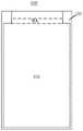
图1A为一种柔性面板的透视图;1A is a perspective view of a flexible panel;
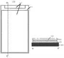
图1B为一种柔性面板的剖视图;1B is a cross-sectional view of a flexible panel;
图2A-2B为一种柔性面板的平面结构示意图;2A-2B are schematic plan views of a flexible panel;
图3A和3B分别为柔性面板中柔性基板和背膜的平面示意图;3A and 3B are schematic plan views of the flexible substrate and the back film in the flexible panel, respectively;
图4为本公开一实施例提供的一种柔性面板的切割方法的流程图;4 is a flowchart of a method for cutting a flexible panel according to an embodiment of the present disclosure;
图5A-5B示出了本公开一实施例提供的柔性面板的切割方法的切割路径;5A-5B illustrate a cutting path of a flexible panel cutting method provided by an embodiment of the present disclosure;
图6为本公开另一实施例提供的一种柔性面板的切割方法的流程图;6 is a flowchart of a method for cutting a flexible panel according to another embodiment of the present disclosure;
图7A-7C示出了本公开另一实施例提供的柔性面板的切割方法的切割路径;7A-7C illustrate a cutting path of a flexible panel cutting method provided by another embodiment of the present disclosure;
图8示出了本公开实施例提供的切割方法中面板单元的移动轨迹;FIG. 8 shows the movement trajectory of the panel unit in the cutting method provided by the embodiment of the present disclosure;
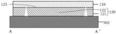
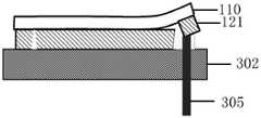
图9A-9B示出了本公开实施例提供的面板单元的剖视图;9A-9B illustrate cross-sectional views of a panel unit provided by an embodiment of the present disclosure;
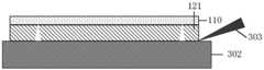
图10A-10B示出了本公开一实施例提供的拾取第一基板部分的方法;10A-10B illustrate a method for picking up a first substrate portion provided by an embodiment of the present disclosure;
图11A-11B示出了本公开另一实施例提供的拾取第一基板部分的方法;及11A-11B illustrate a method for picking up a first substrate portion provided by another embodiment of the present disclosure; and
图12示出了本实施例提供的一种柔性面板的制作装置的功能框图。FIG. 12 shows a functional block diagram of an apparatus for manufacturing a flexible panel provided in this embodiment.
具体实施方式Detailed ways
为使本公开实施例的目的、技术方案和优点更加清楚,下面将结合本公开实施例的附图,对本公开实施例的技术方案进行清楚、完整地描述。显然,所描述的实施例是本公开的一部分实施例,而不是全部的实施例。基于所描述的本公开的实施例,本领域普通技术人员在无需创造性劳动的前提下所获得的所有其他实施例,都属于本公开保护的范围。In order to make the purpose, technical solutions and advantages of the embodiments of the present disclosure more clear, the technical solutions of the embodiments of the present disclosure will be clearly and completely described below with reference to the accompanying drawings of the embodiments of the present disclosure. Obviously, the described embodiments are some, but not all, embodiments of the present disclosure. Based on the described embodiments of the present disclosure, all other embodiments obtained by those of ordinary skill in the art without creative efforts fall within the protection scope of the present disclosure.
除非另外定义,本公开使用的技术术语或者科学术语应当为本公开所属领域内具有一般技能的人士所理解的通常意义。本公开中使用的“第一”、“第二”以及类似的词语并不表示任何顺序、数量或者重要性,而只是用来区分不同的组成部分。“包括”或者“包含”等类似的词语意指出现该词前面的元件或者物件涵盖出现在该词后面列举的元件或者物件及其等同,而不排除其他元件或者物件。“上”、“下”、“左”、“右”等仅用于表示相对位置关系,当被描述对象的绝对位置改变后,则该相对位置关系也可能相应地改变。Unless otherwise defined, technical or scientific terms used in this disclosure shall have the ordinary meaning as understood by one of ordinary skill in the art to which this disclosure belongs. As used in this disclosure, "first," "second," and similar terms do not denote any order, quantity, or importance, but are merely used to distinguish the various components. "Comprises" or "comprising" and similar words mean that the elements or things appearing before the word encompass the elements or things recited after the word and their equivalents, but do not exclude other elements or things. "Up", "Down", "Left", "Right", etc. are only used to represent the relative positional relationship, and when the absolute position of the described object changes, the relative positional relationship may also change accordingly.
如图1A所示,为了实现显示面板的窄边框显示效果,可以将显示面板的至少部分非显示区(NDA),例如焊盘(Bonding Pad,BP)区弯折至显示面板的背面(即与显示侧相反的一侧),因此在显示面板的显示区DA与焊盘区BP之间形成一个弯折区(BA)。在这种情形下,设置于柔性基板120背面的背膜110在该弯折区BA需要实现一个曲率非常大的弯折,这不仅对该背膜的厚度有限制,而且对该背膜的耐弯折性要求很高。因此,通常会将该背膜位于该弯折区的部分去除,形成如图1B所示的柔性面板的结构,以减小弯折应力对于该背膜的影响,同时利于该背膜位于该焊盘区的部分与该显示面板的背面更好的贴合。由于该背膜位于弯折区的部分较窄,在去除时需要较高的对准精度。目前去除该部分背膜的方法包括先将背膜进行图案化处理再与柔性基板进行贴合,或者先进行贴合再用高能量的激光对该部分背膜进行烧灼去除。然而,前一种方法中贴合的精度有限,后一种方法中的激光能量较高,而且容易对该部分背膜所对应的显示面板中的器件结构造成损伤。As shown in FIG. 1A , in order to realize the display effect of the narrow border of the display panel, at least part of the non-display area (NDA) of the display panel, such as the bonding pad (BP) area, can be bent to the back of the display panel (ie, the same as the The side opposite to the display side), so a bent area (BA) is formed between the display area DA and the pad area BP of the display panel. In this case, the
在显示面板的制作过程中,为了提高生产效率、降低生产成本,通常在一块基板上同时形成多个面板单元,然后切割分离成多个独立的面板单元。每个面板单元包括与显示面板对应的面板区以及面板区以外的非面板区,最终形成显示面板还需要再次切割以去除面板单元的非面板区,非面板区例如包括显示面板的检测区,该检测区例如形成有检测电路(例如接触垫)和器件(例如静电环等),用于在显示面板形成之前对显示面板进行检测。In the manufacturing process of the display panel, in order to improve the production efficiency and reduce the production cost, a plurality of panel units are usually formed on a substrate at the same time, and then cut and separated into a plurality of independent panel units. Each panel unit includes a panel area corresponding to the display panel and a non-panel area other than the panel area. The final formation of the display panel also needs to be cut again to remove the non-panel area of the panel unit. For example, the non-panel area includes the detection area of the display panel. For example, the detection area is formed with detection circuits (eg, contact pads) and devices (eg, electrostatic rings, etc.), for detecting the display panel before the display panel is formed.
本公开实施例提供一种柔性面板的制作方法,包括:提供面板单元;去除该面板单元的非面板区,同时一并剥离背膜位于该柔性面板的弯折区内的剥离部分。An embodiment of the present disclosure provides a method for fabricating a flexible panel, including: providing a panel unit; removing a non-panel area of the panel unit, and simultaneously peeling off the peeling portion of the back film located in the bending area of the flexible panel.
本公开实施例提供的柔性面板的制作方法,利用该背膜位于弯折区内的剥离部分与该面板单元的非面板区邻接,在对面板单元进行处理去除其非面板区时一并带离该背膜的剥离部分,克服了该剥离部分本身因形状窄小难以准确剥离的问题,同时不需要额外的背膜剥离工艺步骤,节省了工艺成本,提高了效率,增加了产率。In the manufacturing method of the flexible panel provided by the embodiment of the present disclosure, the peeling part of the back film located in the bending area is adjacent to the non-panel area of the panel unit, and the non-panel area is taken away when the panel unit is processed to remove the non-panel area. The peeling part of the back film overcomes the problem that the peeling part itself is difficult to peel off accurately due to its narrow shape, and at the same time, no additional back film peeling process steps are required, which saves the process cost, improves the efficiency, and increases the yield.
图2A是本公开一实施例用于形成柔性面板的一种面板单元的平面结构示意图。例如,该面板单元用于形成如图1B所示的柔性面板200。如图2A所示,面板单元100包括虚线框以内的面板区101以及位于虚线框之外的非面板区102,其中,面板区101对应于所要形成的柔性面板200,也即面板区101为柔性面板200所在的区域。2A is a schematic plan view of a panel unit for forming a flexible panel according to an embodiment of the present disclosure. For example, the panel unit is used to form the flexible panel 200 as shown in FIG. 1B . As shown in FIG. 2A , the
请一并参照图1B,面板单元100包括层叠设置的柔性基板120和背膜110,柔性基板120包括彼此相对的第一表面123和第二表面124,背膜110设置于第一表面123上。第二表面124为显示侧表面,相应地第一表面123为背侧表面。例如,柔性基板120包括柔性衬底基板以及设置于柔性衬底基板上的显示结构(未示出),显示结构包括用于实现显示功能的像素阵列结构。例如,该显示面板为有机发光二极管(OLED)显示面板,该像素阵列结构包括多条栅线、多条数据线以及由这些栅线、数据线驱动的多个像素单元。每个像素单元包括有机发光二极管以及驱动该有机发光二极管发光的像素电路,该像素电路例如为各种了类型的像素电路,包括常规的2T1C电路或者3T1C电路以及基于它们的具有补偿功能的像素电路等,这里不再赘述。1B , the
例如,该衬底基板为有机柔性材料,例如聚酰亚胺(PI)、聚乙烯对苯二甲酸乙二醇酯(PET)、聚碳酸酯、聚乙烯、聚丙烯酸酯、聚醚酰亚胺、聚醚砜等。For example, the base substrate is an organic flexible material such as polyimide (PI), polyethylene terephthalate (PET), polycarbonate, polyethylene, polyacrylate, polyetherimide , polyethersulfone, etc.
例如,背膜110的材料为有机柔性材料,例如为聚酰亚胺、聚对苯二甲酸乙二醇酯、聚碳酸酯、环烯烃聚合物、聚酰亚胺或者聚丙烯酸酯等。For example, the material of the
例如,柔性基板120还可以包括用于实现触控功能的触控结构等(未示出)。该触控结构例如为互容式触控面板或者自容式触控结构。该触控结构例如为与该显示结构层叠设置的外挂式结构,也可以是整合入该显示面板的内嵌式结构,这里不再赘述。For example, the
图2B示出了面板区内的一种具体布局。例如,如图2B所示,在面板区101内,柔性面板200还包括显示区DA和焊盘区BP。显示面板的像素阵列结构即设置于显示区DA内;焊盘区BP位于显示区DA之外,其中设置有焊盘电极(未示出),用于与外部元件(例如驱动芯片)进行绑定(Bonding),以为显示区的像素阵列结构提供各种信号,例如电源电压信号、时序信号等。显示区DA中的像素阵列结构通过扇出线210与焊盘电极相连以实现像素阵列结构和焊盘电极之间信号的传输,图中示出了该扇出线位于扇出(fan-out)区的部分。弯折区BA位于显示区DA与焊盘区BP之间,通过将弯折区BA进行弯折可以将焊盘区BP弯折至柔性面板200的背面从而实现窄边框显示。例如,弯折区BA位于该扇出区与焊盘区BP之间,将二者分隔开。FIG. 2B shows a specific layout within the panel area. For example, as shown in FIG. 2B , within the
图3A和3B分别示出了面板单元100中柔性基板120和背膜110的平面示意图。例如,在初始的面板单元100中,柔性基板120和背膜110具有相同的图案。请一并参照图3A和图3B,柔性基板120包括第一基板部分121和第二基板部分122,第一基板部分121对应面板单元100的非面板区102,第二基板部分122对应面板区101,也即第一基板部分121和第二基板部分122分别为柔性基板120位于非面板区102和面板区101的部分。背膜110包括第一背膜部分111和第二背膜部分112。第一背膜部分111又包括第一子部113和第二子部114,第一子部113对应非面板区102,第二子部114对应于弯折区BA,也即第一子部113和第二子部114分别为背膜110位于非面板区102与弯折区BA的部分,第二子部114即为背膜110位于弯折区BA内的剥离部分。第二背膜部分112对应于面板区101除弯折区BA以外的区域,也即第二背膜部分112为背膜110位于面板区101的弯折区BA以外的部分,且包括由弯折区BA间隔开的两部分。例如,第一背膜部分111的第一子部113与第一基板部分121具有相同的图案。3A and 3B are schematic plan views of the
在对面板单元100进行处理以得到柔性面板200时,需要去除该面板单元的非面板区部分,也即第一基板部分121和第一背膜部分111的第一子部113。When the
在本公开实施例提供的一种柔性面板的制作方法中,在去除该面板单元的非面板区部分的同时,一并剥离背膜110的第二子部114。In a manufacturing method of a flexible panel provided by an embodiment of the present disclosure, while removing the non-panel area portion of the panel unit, the second sub-portion 114 of the
在本公开的实施例中,该柔性面板的制作方法主要包括两个步骤:In the embodiment of the present disclosure, the manufacturing method of the flexible panel mainly includes two steps:
(一)对通过对该面板单元进行切割处理使得该柔性面板的柔性基板120分离为第一基板部分121和第二基板部分122、背膜110分离为第一背膜部分111和第二背膜部分112;(1) Separating the
(二)再去除该面板单元的非面板区102,同时一并剥离该背膜的第二子部114。(2) Removing the
如图3B所示,由于背膜110的第二子部114与位于非面板区102的第一子部113彼此连接,形成一个整体,在去除该面板单元的非面板区102的同时,拉动背膜110的第一子部113可以一并带离该第二子部114。例如,可以经过上述切割处理,将背膜110的第二子部114与背膜110位于面板区101的其它部分分离并与该背膜位于非面板区102的部分保持连接,从而在除去该背膜的非面板区部分时一并带离该第二子部114,从而在切割面板单元的同时还实现了对背膜的图案化。这不仅可以克服该第二子部本身因形状窄小难以准确剥离的问题,还不需要额外的背膜剥离工艺步骤,节省了工艺成本。As shown in FIG. 3B , since the second sub-section 114 of the
以下,将分别在不同的实施例中对于这两个步骤的实现方法进行示例性说明。Hereinafter, the implementation methods of these two steps will be exemplarily described in different embodiments respectively.
图4示出了本公开一实施例提供的一种柔性面板的切割方法的流程图,图5A-5B示出了该切割方法中对面板单元进行切割的切割路径。如图4所示,该制作方法至少包括以下步骤S41和步骤S42。FIG. 4 shows a flowchart of a method for cutting a flexible panel provided by an embodiment of the present disclosure, and FIGS. 5A-5B show a cutting path for cutting a panel unit in the cutting method. As shown in FIG. 4 , the manufacturing method at least includes the following steps S41 and S42.
步骤S41:将面板单元100放置在第一处理台301上,柔性基板120的第二表面124背离该第一处理台,对柔性基板120进行第一切割处理,以使得柔性基板120分离为第一基板部分121和第二基板部分122。Step S41 : placing the
图5A示出了此步骤中面板单元100的切割路径(如图中虚线所示)和切割深度(如图中缺口所示),该切割深度仅贯穿柔性基板120,也即切割到背膜110的表面为止。在该步骤中,柔性基板120的第二表面124背离该第一处理台301的台面(支撑面),如图所示,如果以柔性基板120的第二表面124(显示侧表面)为正面,则此时柔性基板120相对于第一处理台301正向放置。FIG. 5A shows the cutting path (shown by the dotted line in the figure) and the cutting depth (shown by the notch in the figure) of the
步骤S42:翻转面板单元将柔性基板120置于第二处理台302上,并使得柔性基板120的第一表面123背离第二处理台302,对背膜110进行第二切割处理,使得背膜110分离为第一背膜部分111和第二背膜部分112。Step S42 : turning the panel unit over to place the
图5B示出了此步骤中面板单元100的切割路径(如图中虚线所示)和切割深度(如图中缺口所示),该切割深度仅贯穿背膜110,也即切割到柔性基板120的表面为止。在该步骤中,柔性基板120的第二表面124背离该第二处理台302的台面(支撑面),因此柔性基板120相对于第二处理台302反向放置。FIG. 5B shows the cutting path (shown by the dotted line in the figure) and the cutting depth (shown by the notch in the figure) of the
在柔性基板120正向放置时进行的第一切割处理的切割路径与在柔性基板120反向放置时进行的第二切割处理的切割路径部分重叠,在这些路径重叠部分,两次切割的刀口将彼此贯通,使得面板单元在这些重叠部分被贯穿切割,从而面板单元被分离。The cutting path of the first dicing process performed when the
本实施例提供的柔性面板的切割方法,是在两次切割步骤中分别对柔性基板120和背膜110进行切割处理,使柔性基板120分离为第一基板部分121和第二基板部分122、背膜110分离为第一背膜部分111和第二背膜部分112。The flexible panel cutting method provided in this embodiment is to cut the
图6示出了本公开另一实施例提供的一种柔性面板的切割方法的流程图,图7A-7C示出了切割步骤中对面板单元进行切割的切割路径。如图所示,该制作方法至少包括以下步骤S61和步骤S62。6 shows a flowchart of a method for cutting a flexible panel provided by another embodiment of the present disclosure, and FIGS. 7A-7C show a cutting path for cutting the panel unit in the cutting step. As shown in the figure, the manufacturing method at least includes the following steps S61 and S62.
步骤S61:将面板单元100放置在第一处理台上,柔性基板120的第二表面124背离该第一处理台,对柔性基板120进行第一切割处理以使得柔性基板120分离为第一基板部分121和第二基板部分122;同时,除了第二子部114的周边外,还沿该第一切割处理的切割路径对背膜110进行切割处理。Step S61 : placing the
在此步骤中,柔性基板120和背膜110均进行了切割。此时柔性基板120相对于第一处理台正向放置。图7A和图7B分别示出了此步骤中柔性基板120和背膜110的切割路径(如图中虚线所示)。可以看出,在此步骤中,对柔性基板120的割处理与对背膜110的切割处理具有重合的切割路径,在该重合的切割路径上,对该面板单元100的切割深度贯穿了柔性基板120和背膜110,即对面板单元进行了贯穿切割。但是,在除了该重合的切割路径以外,该面板单元的切割深度仅贯穿柔性基板120,即对面板单元进行了部分切割。In this step, both the
步骤S62:翻转面板单元100将柔性基板120置于第二处理台上,并使得柔性基板120的第一表面123背离该第二处理台,沿第二子部114的周边对背膜110进行第二切割处理,使得背膜110分离为第一背膜部分111和第二背膜部分112。Step S62 : the
在该步骤中,柔性基板120相对于第二处理台反向放置。图7C示出了此步骤中背膜110的切割路径,如图所示,该切割路径为第二子部114与第二背膜部分112连接的两个边,该切割路径仅贯穿背膜110。该第二切割处理中的切割路径与图7B所示的第一切割处理中对背膜110的切割路径连接起来,即形成了图5B所示的切割路径。因此,背膜110经过切割步骤S61和S62,得以分离成第一背膜部分111和第二背膜部分112。In this step, the
本实施例提供的柔性面板的切割方法,将涉及到柔性基板120的切割路径与背膜110的切割路径的重合部分在一次切割步骤中(例如在对柔性基板的切割步骤)中进行,这需要在该经过该重合部分的切割路径时,将切割深度调节为贯穿柔性基板120和背膜110。当然,该重合部分的切割路径也可以在对背膜110的切割步骤中一并进行,本公开实施例对此不作限制。In the cutting method of the flexible panel provided in this embodiment, the overlapping part of the cutting path involving the
本公开的实施例对于具体的切割方法不作限制。例如,可以通过激光切割和刀轮切割实现上述切割处理,可以采用各种适当的激光切割装置以及刀轮切割装置。激光切割装置采用激光发生器输出高功率密度激光束照射被切割材料,使被切割材料很快被加热至汽化温度,且蒸发形成孔洞,随着激光束的移动,完成对被切割材料的切割;刀轮切割装置包括刀轮,刀轮是沿其外周具有切割边缘的盘状件,在切割过程中可被驱动以高速旋转,例如切割边缘为金刚石材料。例如,在采用激光切割时,通过调节激光器输出的激光束的能量实现不同深度的切割路径;在采用刀轮切割时,通过调节刀轮的高度实现不同深度的切割路径。The embodiments of the present disclosure do not limit the specific cutting method. For example, the above-described cutting process can be achieved by laser cutting and cutter wheel cutting, and various suitable laser cutting devices and cutter wheel cutting devices can be used. The laser cutting device uses a laser generator to output a high-power density laser beam to irradiate the material to be cut, so that the material to be cut is quickly heated to the vaporization temperature, and evaporated to form a hole, and with the movement of the laser beam, the cutting of the material to be cut is completed; The cutter wheel cutting device includes a cutter wheel, which is a disk-shaped member with a cutting edge along its outer circumference, which can be driven to rotate at high speed during the cutting process, for example, the cutting edge is a diamond material. For example, when using laser cutting, the cutting path of different depths can be realized by adjusting the energy of the laser beam output by the laser; when cutting using the cutter wheel, the cutting path of different depths can be realized by adjusting the height of the cutter wheel.
例如,图8示出了该切割方法中该面板单元的移动轨迹。如图所示,该面板单元通过真空吸附固定于第一处理台301和第二处理台302上。第一处理台301具有翻转功能。在该第一切割处理完成后,第一处理台301进行翻转,将该面板单元放置于第二处理台302上,之后第一处理台301借助对于面板单元的吸附,将该面板单元通过柔性基板120的第二表面124吸附于第二处理台302上。For example, FIG. 8 shows the movement trajectory of the panel unit in the cutting method. As shown in the figure, the panel unit is fixed on the first processing table 301 and the second processing table 302 by vacuum suction. The
图9A和9B分别示出了经过上述切割后的面板单元的俯视图与沿A-A’方向的剖视图。如图所示,面板单元100置于第二处理台302上,柔性基板120的第一表面123背离第二处理台302,处于反向放置状态。经过上述切割后,柔性基板120分离为第一基板部分121与第二基板部分122,背膜110分离为第一背膜部分111和第二背膜部分112。接下来,就需要去除该柔性面板的非面板区,同时一并剥离该背膜的第二子部114,从而剥离该背膜位于弯折区BA内的剥离部分。9A and 9B respectively show a top view and a cross-sectional view along the A-A' direction of the panel unit after the above-mentioned cutting. As shown in the figure, the
例如,使第一基板部分121与第二处理台302分离,并以第一基板部分121为作用点,去除面板单元100的非面板区,并将背膜110的第二子部114从所述柔性基板剥离。For example, the
例如,从第二处理台302拾取第一基板部分121,将第一基板部分121与第二处理台302分离。For example, the
本公开的实施例对于拾取第一基板部分的方法不作限制。图10A-10B示出了拾取该第一基板部分的一个示例方法。如图10A所示,使用刀片303插入到第一基板部分121与第二处理台302之间,并抬起第一基板部分121。例如,面板单元100通过真空吸附固定于第二处理台302上,利用很薄的刀片303从边缘部分插入到第一基板部分121与第二处理台302之间破坏该第一基板部分与该第二处理台之间的真空吸附,从而容易将该第一基板部分抬起;通常边缘部分没有真空吸附或真空吸附力较小。Embodiments of the present disclosure do not limit the method of picking up the first substrate portion. 10A-10B illustrate an example method of picking up the first substrate portion. As shown in FIG. 10A , a
然后,如图10B所示,使用夹子304夹持该第一基板部分的一端,并带动该第一基板部分以剥离背膜110的第二子部114。在另一个示例中,可以使用真空吸附拾取头替换夹子304,该真空吸附拾取头作用于对应于第一基板部分121的一端的第一背膜部分111的表面,且其施加的吸附力大于第二处理台302对于第一基板部分121的吸附力,从而可以拾取第一基板部分121。Then, as shown in FIG. 10B , one end of the first substrate portion is clamped by a
图11A示出了拾取该第一基板部分的另一个示例方法。如图所示,在第二处理台302中对应于面板单元100的非面板区102设置支撑杆305,也即该支撑杆305对应于第一基板部分121。该支撑杆305可以相对于该第二处理台302在垂直于该第二处理台的台面的方向上发生移动;例如,可以通过螺旋、气压、液压等方式来驱动支撑杆305。在拾取该第一基板部分时,移动该支撑杆305使其突出于该第二处理台302以抬起第一基板部分121。支撑杆可以设置在处理台内部,且由设置在处理台内的驱动机构驱动;或者,支撑杆可以通过贯穿处理台的通孔提供,且由设置在处理台外的驱动机构驱动。FIG. 11A illustrates another example method of picking up the first substrate portion. As shown in the figure, a
例如,第二处理台302可以对应于面板单元100的面板区101和非面板区102分别设置独立的真空吸附气路。如图11B,第二处理台302中对应于面板单元100的面板区101和非面板区102分别设置有第一真空气路306和第二真空气路307。在进行切割处理时,第一真空气路306和第二真空气路307均开启,从而将面板单元100的整个区域均吸附于第二处理台302上,从而确保了面板单元100的平整性以方便切割。在进行分离处理时,保持第一真空气路306开启,关闭第二真空气路307,从而便于面板单元100的非面板区102从该第二处理台分离。For example, the
本公开实施例还提供一种柔性面板的制作装置,用于实施上述柔性面板的制作方法。该制作装置包括背膜去除单元,该背膜去除单元配置为去除面板单元100的非面板区102,同时一并剥离背膜110位于柔性面板200的弯折区BA内的剥离部分,也即背膜110的第二子部114。Embodiments of the present disclosure further provide a manufacturing device for a flexible panel, which is used to implement the above-mentioned manufacturing method for a flexible panel. The manufacturing apparatus includes a back film removing unit, which is configured to remove the
图12示出了本实施例提供的一种柔性面板的制作装置的功能框图。该制作装置400主要包括切割单元、传送单元、第一处理台、第二处理台以及背膜废弃单元,集成了传送功能、切割功能、翻转功能及去背膜功能等多种功能。FIG. 12 shows a functional block diagram of an apparatus for manufacturing a flexible panel provided in this embodiment. The
例如,传送单元可以采用各种适当的形式,例如传送带、机械臂等;切割单元可以采用适当的形式,包括切割部,该切割部可以为激光切割部或导轮切割部,根据需要切割单元还可以包括用于沿设定路径移动切割部的驱动机构等;该第一处理台除包括台面以及吸附装置之外,还可以集成具有翻转功能的翻转单元,用于翻转待切割的面板单元,该翻转单元例如包括机械臂,其可以将台面翻转180度;该第二处理台除包括台面以及吸附装置之外,还可以集成具有去背膜功能的背膜去除单元,用于去除面板单元的非面板区,该背膜去除单元包括刀片或支撑杆,以及包括夹子或真空吸附头等;背膜废弃单元可以包括容器,以收纳被去除的面板单元的非面板区。For example, the conveying unit can take various appropriate forms, such as a conveyor belt, a robotic arm, etc.; the cutting unit can take an appropriate form, including a cutting part, which can be a laser cutting part or a guide wheel cutting part, and the cutting unit can also be used as required. It can include a drive mechanism for moving the cutting part along the set path, etc.; in addition to the table top and the adsorption device, the first processing table can also integrate a turning unit with a turning function for turning the panel unit to be cut. The turning unit includes, for example, a robotic arm, which can turn the table top by 180 degrees; the second processing table, in addition to the table top and the adsorption device, can also integrate a back film removal unit with a back film removal function, which is used to remove the non-contact surface of the panel unit. The panel area, the backing film removal unit includes a blade or a support rod, and includes a clip or a vacuum suction head, etc.; the backing film discarding unit may include a container to receive the non-panel area of the removed panel unit.
例如,该制作装置的工作过程主要包括:从面板单元载入口载入待切割的面板单元并通过传送单元将该面板单元传送至第一处理台;第一处理台吸附固定该面板单元,之后使用切割单元对该面板单元进行第一切割处理;然后使用翻转单元将该面板单元翻转,并置于第二处理台上,第二处理台吸附固定该面板单元,使用激光单元对该面板单元进行第二切割处理;接着使用背膜去除单元去除该面板单元的非面板区,并且同时剥离背膜位于弯折区内的剥离部分(例如上述实施例中的第二子部),将该去除部分送入背膜废弃单元进行回收处理;最后,利用传送单元将该面板单元送入面板单元出口。For example, the working process of the manufacturing device mainly includes: loading the panel unit to be cut from the panel unit loading port and transferring the panel unit to the first processing station through the conveying unit; the first processing station adsorbs and fixes the panel unit, and then Use the cutting unit to perform the first cutting process on the panel unit; then use the turning unit to turn the panel unit over and place it on the second processing table, the second processing table adsorbs and fixes the panel unit, and uses the laser unit to perform the cutting process on the panel unit. The second cutting process; then use the back film removing unit to remove the non-panel area of the panel unit, and at the same time peel off the peeling part of the back film in the bending area (for example, the second sub-section in the above-mentioned embodiment), the removed part It is sent to the backing film waste unit for recycling; finally, the panel unit is sent to the outlet of the panel unit by the conveying unit.
以上所述,仅为本公开的具体实施方式,但本公开的保护范围并不局限于此,任何熟悉本技术领域的技术人员在本公开揭露的技术范围内,可轻易想到变化或替换,都应涵盖在本公开的保护范围之内。因此,本公开的保护范围应以所述权利要求的保护范围为准。The above are only specific embodiments of the present disclosure, but the protection scope of the present disclosure is not limited to this. should be included within the scope of protection of the present disclosure. Therefore, the protection scope of the present disclosure should be based on the protection scope of the claims.
Claims (14)
Priority Applications (5)
| Application Number | Priority Date | Filing Date | Title |
|---|---|---|---|
| CN201810812395.3ACN110828505B (en) | 2018-07-23 | 2018-07-23 | Manufacturing method and manufacturing device of flexible panel |
| JP2019565495AJP7381346B2 (en) | 2018-07-23 | 2019-07-09 | Flexible panel manufacturing method and manufacturing equipment |
| US16/632,734US11331899B2 (en) | 2018-07-23 | 2019-07-09 | Manufacturing method and manufacturing device of flexible display panel |
| PCT/CN2019/095185WO2020019974A1 (en) | 2018-07-23 | 2019-07-09 | Method and apparatus for manufacturing flexible panel |
| EP19835344.3AEP3828697A4 (en) | 2018-07-23 | 2019-07-09 | Method and apparatus for manufacturing flexible panel |
Applications Claiming Priority (1)
| Application Number | Priority Date | Filing Date | Title |
|---|---|---|---|
| CN201810812395.3ACN110828505B (en) | 2018-07-23 | 2018-07-23 | Manufacturing method and manufacturing device of flexible panel |
Publications (2)
| Publication Number | Publication Date |
|---|---|
| CN110828505A CN110828505A (en) | 2020-02-21 |
| CN110828505Btrue CN110828505B (en) | 2022-06-07 |
Family
ID=69180726
Family Applications (1)
| Application Number | Title | Priority Date | Filing Date |
|---|---|---|---|
| CN201810812395.3AActiveCN110828505B (en) | 2018-07-23 | 2018-07-23 | Manufacturing method and manufacturing device of flexible panel |
Country Status (5)
| Country | Link |
|---|---|
| US (1) | US11331899B2 (en) |
| EP (1) | EP3828697A4 (en) |
| JP (1) | JP7381346B2 (en) |
| CN (1) | CN110828505B (en) |
| WO (1) | WO2020019974A1 (en) |
Families Citing this family (2)
| Publication number | Priority date | Publication date | Assignee | Title |
|---|---|---|---|---|
| CN113947994B (en)* | 2020-07-15 | 2023-01-10 | 京东方科技集团股份有限公司 | Display panel and display device |
| CN112614434B (en)* | 2020-12-30 | 2022-07-12 | 武汉华星光电半导体显示技术有限公司 | Flexible display device |
Citations (15)
| Publication number | Priority date | Publication date | Assignee | Title |
|---|---|---|---|---|
| WO2006023875A1 (en)* | 2004-08-23 | 2006-03-02 | Avery Dennison Corporation | Apparatus, system, and method for personalizing a portable electronic device |
| CN103928398A (en)* | 2013-12-25 | 2014-07-16 | 厦门天马微电子有限公司 | A kind of flexible display panel and its preparation method, flexible display device |
| CN104218184A (en)* | 2013-05-29 | 2014-12-17 | 株式会社日本显示器 | Display device and method for producing the same |
| CN105989783A (en)* | 2015-03-17 | 2016-10-05 | 乐金显示有限公司 | Back plate member for flexible display, display apparatus including the same, and method of manufacturing the same |
| CN106098550A (en)* | 2016-08-19 | 2016-11-09 | 京东方科技集团股份有限公司 | The preparation method of flexible display panels and the preparation method of flexible display apparatus |
| CN106710451A (en)* | 2017-03-06 | 2017-05-24 | 京东方科技集团股份有限公司 | Flexible display panel and support shaft making method thereof |
| CN106910428A (en)* | 2017-03-02 | 2017-06-30 | 京东方科技集团股份有限公司 | The preparation method and flexible display apparatus of bending type flexible base board |
| CN106910429A (en)* | 2017-03-08 | 2017-06-30 | 京东方科技集团股份有限公司 | A kind of flexible module and preparation method thereof |
| CN106935596A (en)* | 2017-02-22 | 2017-07-07 | 武汉华星光电技术有限公司 | A kind of preparation method of flexible base board |
| CN107195802A (en)* | 2017-06-05 | 2017-09-22 | 京东方科技集团股份有限公司 | A kind of flexible display apparatus and preparation method thereof |
| CN107403882A (en)* | 2017-08-08 | 2017-11-28 | 京东方科技集团股份有限公司 | A kind of preparation method of flexible display |
| CN107819072A (en)* | 2016-09-13 | 2018-03-20 | 乐金显示有限公司 | Support film, organic light-emitting display device and manufacturing method thereof |
| CN108062914A (en)* | 2018-01-05 | 2018-05-22 | 京东方科技集团股份有限公司 | Display base plate and its manufacturing method, display device |
| CN108257508A (en)* | 2016-12-28 | 2018-07-06 | 乐金显示有限公司 | Flexible display apparatus and its manufacturing method |
| CN108257913A (en)* | 2016-12-29 | 2018-07-06 | 上海和辉光电有限公司 | A kind of preparation method of flexible display |
Family Cites Families (18)
| Publication number | Priority date | Publication date | Assignee | Title |
|---|---|---|---|---|
| JP3194911B2 (en)* | 1998-12-24 | 2001-08-06 | 大平技研工業株式会社 | Seal vending machine |
| DE10065457B4 (en)* | 2000-12-28 | 2007-04-26 | Karl Marbach Gmbh & Co. Kg | Method and device for separating the use and waste of a stamped or cut sheet of material and plant for producing benefits from a sheet of material |
| US7905977B2 (en)* | 2006-11-17 | 2011-03-15 | Sipix Imaging, Inc. | Post conversion methods for display devices |
| TWI410329B (en)* | 2009-03-09 | 2013-10-01 | Ind Tech Res Inst | Apparatus for releasing a flexible device and method thereof |
| KR100963496B1 (en)* | 2009-06-12 | 2010-06-17 | 주식회사 토비스 | Method for cutting liquid crystal panel and method for manufacturing liquid crystal panel using the same |
| FI124203B (en)* | 2010-01-20 | 2014-04-30 | Marisense Oy | Method and apparatus for treating display laminates |
| JP2012137607A (en) | 2010-12-27 | 2012-07-19 | Sony Corp | Display device, manufacturing method thereof and electronic apparatus |
| KR102117890B1 (en) | 2012-12-28 | 2020-06-02 | 엘지디스플레이 주식회사 | Flexible display device and method for manufacturing the same |
| WO2014157351A1 (en)* | 2013-03-28 | 2014-10-02 | 富士フイルム株式会社 | Electroacoustic conversion film, electroacoustic converter, flexible display, and projector screen |
| CN203457406U (en)* | 2013-07-16 | 2014-02-26 | 漳州市福世通电子有限公司 | Flexible circuit board capable of being bent for 90 degrees |
| KR102111628B1 (en) | 2013-07-25 | 2020-06-09 | 삼성디스플레이 주식회사 | flexible touch screen panel and flexible display device with the same |
| TWI671141B (en) | 2013-08-30 | 2019-09-11 | 半導體能源研究所股份有限公司 | Support supply apparatus and method for supplying support |
| WO2015170210A1 (en)* | 2014-05-03 | 2015-11-12 | Semiconductor Energy Laboratory Co., Ltd. | Separation apparatus for thin film stacked body |
| US10582612B2 (en)* | 2014-06-30 | 2020-03-03 | Lg Display Co., Ltd. | Flexible display device with reduced bend stress wires and manufacturing method for the same |
| US20170271380A1 (en)* | 2016-03-16 | 2017-09-21 | Semiconductor Energy Laboratory Co., Ltd. | Peeling method |
| KR102671371B1 (en)* | 2016-10-07 | 2024-06-04 | 삼성디스플레이 주식회사 | Flexible display apparatus and manufacturing method thereof |
| KR102691911B1 (en)* | 2016-12-22 | 2024-08-07 | 삼성디스플레이 주식회사 | Flexible display panel, method for manufacturing flexible display panel, and apparatus for manufacturing flexible display panel |
| CN111162203B (en) | 2020-01-02 | 2023-10-31 | 京东方科技集团股份有限公司 | Back film and preparation method thereof, flexible display device and preparation method thereof, and cutting die |
- 2018
- 2018-07-23CNCN201810812395.3Apatent/CN110828505B/enactiveActive
- 2019
- 2019-07-09EPEP19835344.3Apatent/EP3828697A4/ennot_activeWithdrawn
- 2019-07-09USUS16/632,734patent/US11331899B2/enactiveActive
- 2019-07-09WOPCT/CN2019/095185patent/WO2020019974A1/ennot_activeCeased
- 2019-07-09JPJP2019565495Apatent/JP7381346B2/enactiveActive
Patent Citations (15)
| Publication number | Priority date | Publication date | Assignee | Title |
|---|---|---|---|---|
| WO2006023875A1 (en)* | 2004-08-23 | 2006-03-02 | Avery Dennison Corporation | Apparatus, system, and method for personalizing a portable electronic device |
| CN104218184A (en)* | 2013-05-29 | 2014-12-17 | 株式会社日本显示器 | Display device and method for producing the same |
| CN103928398A (en)* | 2013-12-25 | 2014-07-16 | 厦门天马微电子有限公司 | A kind of flexible display panel and its preparation method, flexible display device |
| CN105989783A (en)* | 2015-03-17 | 2016-10-05 | 乐金显示有限公司 | Back plate member for flexible display, display apparatus including the same, and method of manufacturing the same |
| CN106098550A (en)* | 2016-08-19 | 2016-11-09 | 京东方科技集团股份有限公司 | The preparation method of flexible display panels and the preparation method of flexible display apparatus |
| CN107819072A (en)* | 2016-09-13 | 2018-03-20 | 乐金显示有限公司 | Support film, organic light-emitting display device and manufacturing method thereof |
| CN108257508A (en)* | 2016-12-28 | 2018-07-06 | 乐金显示有限公司 | Flexible display apparatus and its manufacturing method |
| CN108257913A (en)* | 2016-12-29 | 2018-07-06 | 上海和辉光电有限公司 | A kind of preparation method of flexible display |
| CN106935596A (en)* | 2017-02-22 | 2017-07-07 | 武汉华星光电技术有限公司 | A kind of preparation method of flexible base board |
| CN106910428A (en)* | 2017-03-02 | 2017-06-30 | 京东方科技集团股份有限公司 | The preparation method and flexible display apparatus of bending type flexible base board |
| CN106710451A (en)* | 2017-03-06 | 2017-05-24 | 京东方科技集团股份有限公司 | Flexible display panel and support shaft making method thereof |
| CN106910429A (en)* | 2017-03-08 | 2017-06-30 | 京东方科技集团股份有限公司 | A kind of flexible module and preparation method thereof |
| CN107195802A (en)* | 2017-06-05 | 2017-09-22 | 京东方科技集团股份有限公司 | A kind of flexible display apparatus and preparation method thereof |
| CN107403882A (en)* | 2017-08-08 | 2017-11-28 | 京东方科技集团股份有限公司 | A kind of preparation method of flexible display |
| CN108062914A (en)* | 2018-01-05 | 2018-05-22 | 京东方科技集团股份有限公司 | Display base plate and its manufacturing method, display device |
Also Published As
| Publication number | Publication date |
|---|---|
| US11331899B2 (en) | 2022-05-17 |
| JP7381346B2 (en) | 2023-11-15 |
| JP2021531484A (en) | 2021-11-18 |
| EP3828697A1 (en) | 2021-06-02 |
| EP3828697A4 (en) | 2022-04-20 |
| WO2020019974A1 (en) | 2020-01-30 |
| CN110828505A (en) | 2020-02-21 |
| US20210138782A1 (en) | 2021-05-13 |
Similar Documents
| Publication | Publication Date | Title |
|---|---|---|
| TWI433625B (en) | Method for fabricating the flexible electronic device | |
| CN102057313B (en) | Motherboard substrate processing method | |
| TWI863943B (en) | Method of peeling mother protective film and method of manufacturing organic light-emitting display apparatus using the same | |
| TWI428243B (en) | Method for debonding a flexible device | |
| CN107851734A (en) | Flexible electronic manufacturing equipment | |
| US20130071220A1 (en) | Semiconductor chip pick-up method and semiconductor chip pick-up apparatus | |
| CN110828505B (en) | Manufacturing method and manufacturing device of flexible panel | |
| KR20180063418A (en) | Display device and method of manufacturing the same | |
| JP2001085360A (en) | Pasting method for electronic part and formation method for ditching on adhesive tape | |
| JP6386866B2 (en) | Separation device and separation method | |
| CN101236322A (en) | Manufacturing method of electro-optic device, manufacturing device of electro-optical device | |
| CN110815328B (en) | Cutting device | |
| KR102511887B1 (en) | system for transferring substrate | |
| US10334742B2 (en) | Method of manufacturing an electric device based on glass substrate | |
| JP6888812B2 (en) | Flexible device manufacturing equipment and manufacturing method | |
| JP2016154198A (en) | Sheet peeling device and peeling method | |
| JP2015191993A (en) | Semiconductor manufacturing device and semiconductor manufacturing method | |
| JP6228058B2 (en) | Semiconductor manufacturing apparatus and semiconductor manufacturing method | |
| JP6633447B2 (en) | Wafer processing method | |
| TW202046824A (en) | El method of manufacturing flexible organic electro luminescence display | |
| JP6270525B2 (en) | Semiconductor manufacturing method and semiconductor manufacturing apparatus | |
| KR102469385B1 (en) | Spacing device and spacing method | |
| WO2024057919A1 (en) | Method of producing glass article, method of producing electronic device, and substrate peeling jig | |
| JP2016081973A (en) | Separation device and separation method | |
| JP2022058206A (en) | Method for treating laminated substrate |
Legal Events
| Date | Code | Title | Description |
|---|---|---|---|
| PB01 | Publication | ||
| PB01 | Publication | ||
| SE01 | Entry into force of request for substantive examination | ||
| SE01 | Entry into force of request for substantive examination | ||
| GR01 | Patent grant | ||
| GR01 | Patent grant |