CN110824457A - A three-dimensional laser scanning system that avoids occlusion - Google Patents
A three-dimensional laser scanning system that avoids occlusionDownload PDFInfo
- Publication number
- CN110824457A CN110824457ACN201911069037.9ACN201911069037ACN110824457ACN 110824457 ACN110824457 ACN 110824457ACN 201911069037 ACN201911069037 ACN 201911069037ACN 110824457 ACN110824457 ACN 110824457A
- Authority
- CN
- China
- Prior art keywords
- scanning
- dimensional laser
- scan
- center
- base
- Prior art date
- Legal status (The legal status is an assumption and is not a legal conclusion. Google has not performed a legal analysis and makes no representation as to the accuracy of the status listed.)
- Granted
Links
- 238000005259measurementMethods0.000claimsdescription7
- 238000000034methodMethods0.000claimsdescription7
- 238000010586diagramMethods0.000description5
- 230000009286beneficial effectEffects0.000description1
- 230000000694effectsEffects0.000description1
- 238000005286illuminationMethods0.000description1
Images
Classifications
- G—PHYSICS
- G01—MEASURING; TESTING
- G01S—RADIO DIRECTION-FINDING; RADIO NAVIGATION; DETERMINING DISTANCE OR VELOCITY BY USE OF RADIO WAVES; LOCATING OR PRESENCE-DETECTING BY USE OF THE REFLECTION OR RERADIATION OF RADIO WAVES; ANALOGOUS ARRANGEMENTS USING OTHER WAVES
- G01S7/00—Details of systems according to groups G01S13/00, G01S15/00, G01S17/00
- G01S7/48—Details of systems according to groups G01S13/00, G01S15/00, G01S17/00 of systems according to group G01S17/00
- G01S7/481—Constructional features, e.g. arrangements of optical elements
- G01S7/4817—Constructional features, e.g. arrangements of optical elements relating to scanning
- G—PHYSICS
- G01—MEASURING; TESTING
- G01S—RADIO DIRECTION-FINDING; RADIO NAVIGATION; DETERMINING DISTANCE OR VELOCITY BY USE OF RADIO WAVES; LOCATING OR PRESENCE-DETECTING BY USE OF THE REFLECTION OR RERADIATION OF RADIO WAVES; ANALOGOUS ARRANGEMENTS USING OTHER WAVES
- G01S17/00—Systems using the reflection or reradiation of electromagnetic waves other than radio waves, e.g. lidar systems
- G01S17/02—Systems using the reflection of electromagnetic waves other than radio waves
- G01S17/06—Systems determining position data of a target
- G01S17/08—Systems determining position data of a target for measuring distance only
- G—PHYSICS
- G01—MEASURING; TESTING
- G01S—RADIO DIRECTION-FINDING; RADIO NAVIGATION; DETERMINING DISTANCE OR VELOCITY BY USE OF RADIO WAVES; LOCATING OR PRESENCE-DETECTING BY USE OF THE REFLECTION OR RERADIATION OF RADIO WAVES; ANALOGOUS ARRANGEMENTS USING OTHER WAVES
- G01S17/00—Systems using the reflection or reradiation of electromagnetic waves other than radio waves, e.g. lidar systems
- G01S17/88—Lidar systems specially adapted for specific applications
- Y—GENERAL TAGGING OF NEW TECHNOLOGICAL DEVELOPMENTS; GENERAL TAGGING OF CROSS-SECTIONAL TECHNOLOGIES SPANNING OVER SEVERAL SECTIONS OF THE IPC; TECHNICAL SUBJECTS COVERED BY FORMER USPC CROSS-REFERENCE ART COLLECTIONS [XRACs] AND DIGESTS
- Y02—TECHNOLOGIES OR APPLICATIONS FOR MITIGATION OR ADAPTATION AGAINST CLIMATE CHANGE
- Y02A—TECHNOLOGIES FOR ADAPTATION TO CLIMATE CHANGE
- Y02A90/00—Technologies having an indirect contribution to adaptation to climate change
- Y02A90/10—Information and communication technologies [ICT] supporting adaptation to climate change, e.g. for weather forecasting or climate simulation
Landscapes
- Engineering & Computer Science (AREA)
- Physics & Mathematics (AREA)
- Computer Networks & Wireless Communication (AREA)
- General Physics & Mathematics (AREA)
- Radar, Positioning & Navigation (AREA)
- Remote Sensing (AREA)
- Electromagnetism (AREA)
- Mechanical Optical Scanning Systems (AREA)
- Optical Radar Systems And Details Thereof (AREA)
Abstract
Translated fromChinese
Description
Translated fromChinese技术领域technical field
本发明涉及激光扫描技术领域,尤其是一种避免遮挡的三维激光扫描系统。The invention relates to the technical field of laser scanning, in particular to a three-dimensional laser scanning system that avoids occlusion.
背景技术Background technique
激光扫描系统的理论研究在现实生活中被广泛应用,如无人驾驶汽车,机器人导航,建筑物重建和遥感。激光扫描系统通过估计从激光雷达发出的光和从远处物体反射的光的到达时间间隔,来测量激光发射点到物体的距离,相比于图像,其不受光照影响有其独特优势。The theoretical study of laser scanning systems is widely used in real life, such as driverless cars, robot navigation, building reconstruction and remote sensing. The laser scanning system measures the distance from the laser emission point to the object by estimating the arrival time interval of the light emitted from the lidar and the light reflected from the distant object. Compared with the image, it has its unique advantage that it is not affected by the illumination.
现有的激光扫描产品的水平扫描旋转中心和竖直扫描旋转中心重合于光源原点,所以可看作是所有扫描光线都是从光源原点发出,故而存在单点光源情况下的遮挡问题,周围物体距离光源原点越近,物体尺寸越大,遮挡现象就越严重。The horizontal scanning rotation center and the vertical scanning rotation center of the existing laser scanning products coincide with the origin of the light source, so it can be considered that all scanning rays are emitted from the origin of the light source, so there is a problem of occlusion in the case of a single-point light source, surrounding objects The closer it is to the origin of the light source, the larger the object size, and the more serious the occlusion phenomenon.
发明内容SUMMARY OF THE INVENTION
针对现有技术的不足,本发明提供一种避免遮挡的三维激光扫描系统,本发明通过改变激光扫描系统的,水平扫描旋转中心和竖直扫描旋转中心的距离,并使竖直扫描旋转中心围绕水平扫描旋转中心旋转,采用行星环绕的扫描方法来达到减小被遮挡区域的效果,并且可根据物体的尺寸及距离,调整系统,以减少被遮挡区域。In view of the shortcomings of the prior art, the present invention provides a three-dimensional laser scanning system that avoids occlusion. The present invention changes the distance between the horizontal scanning rotation center and the vertical scanning rotation center of the laser scanning system, and makes the vertical scanning rotation center around The horizontal scanning rotation center rotates, and the planet-circling scanning method is used to achieve the effect of reducing the occluded area, and the system can be adjusted according to the size and distance of the object to reduce the occluded area.
本发明的技术方案为:一种避免遮挡的三维激光扫描系统,所述的扫描系统包括云台、设置在云台上的旋转盘,以及设置在旋转盘上的旋转臂,所述的旋转臂的端部设置有二维激光扫描仪;通过旋转盘转动带动旋转臂驱动二维激光扫描仪转动,二维激光扫描仪在被带着转动的同时进行扫描测距;扫描方法具体如下:The technical scheme of the present invention is as follows: a three-dimensional laser scanning system that avoids occlusion, the scanning system includes a pan/tilt, a rotary disk arranged on the pan/tilt, and a rotary arm provided on the rotary disk, the rotary arm A two-dimensional laser scanner is arranged at the end of the 2-D laser scanner; the rotating arm is driven by the rotating disk to drive the two-dimensional laser scanner to rotate, and the two-dimensional laser scanner is carried and rotated while scanning and ranging; the scanning method is as follows:
S1)、设定云台的旋转盘的旋转中心为坐标原点Obase,一维云台的旋转盘的旋转面为基平面,二维激光扫描仪的扫描面为扫描平面Пscan;二维激光扫描仪的扫描中心Oscan与坐标原点Obase之间的距离即为扫描臂长度R′;S1), the center of rotation of the rotating disk of the setting head is the coordinate origin Obase , the plane of rotation of the rotating disk of the one-dimensional head is the base plane, and the scanning plane of the two-dimensional laser scanner is the scanning plane Пscan ; The distance between the scanning center Oscan of the scanner and the coordinate origin Obase is the scanning arm length R′;
S2)、设定遮挡物在基平面上的投影的最小外接圆半径为r,基平面中心Obase到遮挡物中心Cocclusion的距离为docclusion,则被遮挡区域的面积S,其计算式如下:S2), set the minimum circumscribed circle radius of the projection of the occluder on the base plane as r, and the distance from the base plane center Obase to the occlusion center Cocclusion is docclusion , then the area S of the occluded area is calculated as follows :
S3)、根据给定的遮挡物的半径r′和距离允许的最大遮挡面积S*,根据上式得到扫描臂长度R′;S3), according to the radius r' and distance of the given occluder The maximum allowable occlusion area S* , the scan arm length R′ is obtained according to the above formula;
S4)、进行三维场景激光扫描,扫描平面中心点Oscan在基平面上绕Z轴旋转,旋转角度为


S5)、根据扫描臂长度R′将扫描点集合Q转换为以坐标原点Obase为中心的空间点集P。S5), according to the scanning arm length R', convert the scanning point set Q into a space point set P centered on the coordinate origin Obase .
优选的,可由下式得到空间点集P的笛卡尔坐标:Preferably, the Cartesian coordinates of the space point set P can be obtained by the following formula:

优选的,在扫描前,先通过标定获取任意一个二维激光扫描仪的扫描中心Oscan与坐标原点Obase之间的距离即为扫描臂长度R,并通过测量获取旋转臂的长度L,并通过R-L得到扫描中心Oscan与坐标原点Obase之间不可通过测量获得距离L′;具体包括以下步骤:Preferably, before scanning, the distance between the scanning center Oscan of any two-dimensional laser scanner and the coordinate origin Obase is obtained by calibration, which is the length R of the scanning arm, and the length L of the rotating arm is obtained by measuring, and Obtaining the distance L' between the scan center Oscan and the coordinate origin Obase through RL, the distance L' cannot be obtained by measurement; specifically, the following steps are included:
S201)、竖直放置一块标定平板,并将扫描系统水平放置于标定平板前方;S201), place a calibration plate vertically, and place the scanning system horizontally in front of the calibration plate;
S202)、启动扫描系统进行扫描并获取相应的扫描数据;S202), start the scanning system to scan and obtain corresponding scanning data;
S203)、将超出标定平板范围的数据去除,保留标定平板范围内的数据;S203), remove the data beyond the scope of the calibration plate, and retain the data within the scope of the calibration plate;
S204)、对每个发射角度θLIDAR对应的点集合

S205)、对每个旋转角度


S206)、根据点集合和

其中dbase为云台旋转中心到标定平板的距离,Δθ为二维激光扫描仪角度误差,
优选的,步骤S2)中,通过将扫描臂长度R′与扫描中心Oscan与坐标原点Obase之间不可通过测量获得距离L′的差值,即可得到根据定遮挡物确定的旋转臂L″,即L″=R′-L′,以实现根据遮挡物的大小调整旋转臂的长度。Preferably, in step S2), by measuring the difference between the scan arm length R' and the scan center Oscan and the coordinate origin Obase , the distance L' cannot be obtained by measurement, the rotating arm L determined according to the fixed obstruction can be obtained. ", that is, L"=R'-L', so that the length of the rotating arm can be adjusted according to the size of the obstruction.
本发明的有益效果为:本发明利用长臂结构把激光扫描中心与云台旋转中心分离,使得激光不在是从一点发出,而是沿着旋转轨迹发出,增大了激光扫描系统的扫描覆盖区域,有效的减小了被遮挡的扫描区域;解决对未知复杂度场景内的被遮挡问题。The beneficial effects of the present invention are as follows: the present invention uses the long arm structure to separate the laser scanning center from the rotation center of the pan/tilt, so that the laser is not emitted from a point, but is emitted along the rotation track, thereby increasing the scanning coverage area of the laser scanning system , effectively reducing the occluded scanning area; solving the occlusion problem in unknown complexity scenes.
附图说明Description of drawings
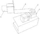
图1为本发明的结构示意图;Fig. 1 is the structural representation of the present invention;
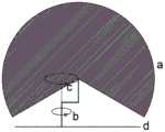
图2为本发明二维激光扫描仪扫描区域图,其中,b为旋转盘旋转路径,c为二维激光扫描仪旋转路径,d为水平面;Fig. 2 is the scanning area diagram of the two-dimensional laser scanner of the present invention, wherein, b is the rotation path of the rotating disk, c is the rotation path of the two-dimensional laser scanner, and d is the horizontal plane;
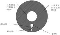
图3为本发明在遮挡物遮挡情况下的扫描图;Fig. 3 is the scanning diagram of the present invention under the condition of occlusion;
图4为现有技术在遮挡物遮挡情况下的扫描图;FIG. 4 is a scanning diagram of the prior art under the condition of being blocked by an occluder;
图5为本发明扫描方法的结构示意图,其中,激光扫描中心与云台旋转中心的距离R,云台旋转中心与遮挡物中心的距离dc,遮挡物半径r,遮挡区域长度x,遮挡区域角度α的几何关系图,黑色阴影为遮挡区域面积S,与基旋转圆形和遮挡物圆形都相切的两条切线相交于点P;5 is a schematic structural diagram of the scanning method of the present invention, wherein the distance R between the laser scanning center and the rotation center of the pan/tilt, the distance dc between the rotation center of the pan/tilt and the center of the obstruction, the radius of the obstruction r, the length of the obstruction area x, the obstruction area The geometric relationship diagram of the angle α, the black shadow is the area S of the occlusion area, and the two tangent lines that are tangent to both the base rotation circle and the occluder circle intersect at point P;
图中,1-云台,2-旋转盘,3-旋转臂,4-二维激光扫描仪。In the figure, 1-head, 2-rotating disk, 3-rotating arm, 4-two-dimensional laser scanner.
具体实施方式Detailed ways
下面结合附图对本发明的具体实施方式作进一步说明:The specific embodiments of the present invention will be further described below in conjunction with the accompanying drawings:
如图1所示,一种避免遮挡的三维激光扫描系统,所述的扫描系统包括云台1、设置在云台1上的旋转盘2,以及设置在旋转盘2上的旋转臂3,所述的旋转臂3的端部设置有二维激光扫描仪4;其中,旋转臂为L型的平板,并且该平板两端均开设有多个安装孔,一端安装在旋转盘2上,另一端安装并支撑二维激光扫描仪4;二维激光扫描仪4的扫描平面与旋转臂3平行。通过旋转盘2转动带动旋转臂3驱动二维激光扫描仪4转动,二维激光扫描仪4在被带着转动的同时进行扫描测距。As shown in FIG. 1, a three-dimensional laser scanning system that avoids occlusion, the scanning system includes a pan-tilt 1, a rotating
如图2-5所示,扫描方法具体如下:As shown in Figure 2-5, the scanning method is as follows:
S1)、设定云台的旋转盘的旋转中心为坐标原点Obase,一维云台的旋转盘的旋转面为基平面,二维激光扫描仪的扫描面为扫描平面Πscan;二维激光扫描仪的扫描中心Oscan与坐标原点Obase之间的距离即为扫描臂长度R′。S1), the center of rotation of the rotating disk of the setting head is the coordinate origin Obase , the plane of rotation of the rotating disk of the one-dimensional head is the base plane, and the scanning plane of the two-dimensional laser scanner is the scanning plane Πscan ; The two-dimensional laser The distance between the scanning center Oscan of the scanner and the coordinate origin Obase is the scanning arm length R'.
由于扫描臂长度R′为二维激光扫描仪的扫描中心Oscan与坐标原点Obase之间的距离,其中仅旋转臂的长度可通过测量获取,因此,在扫描前需要先对系统进行标定,以确定扫描中心Oscan与坐标原点Obase之间不可通过测量得到的距离L′。Since the scanning arm length R' is the distance between the scanning center Oscan of the two-dimensional laser scanner and the coordinate origin Obase , only the length of the rotating arm can be obtained by measurement. Therefore, the system needs to be calibrated before scanning. To determine the distance L' that cannot be obtained by measurement between the scan center Oscan and the coordinate origin Obase .
扫描前以任意长度L的旋转臂作为标定,并设定标定的二维激光扫描仪的扫描中心Oscan与坐标原点Obase之间的距离即为扫描臂长度R,并通过R-L得到扫描中心Oscan与坐标原点Obase之间不可通过测量获得距离L′;具体包括以下步骤:Before scanning, a rotating arm of any length L is used as calibration, and the distance between the scanning center Oscan of the calibrated two-dimensional laser scanner and the coordinate origin Obase is the scanning arm length R, and the scanning center O is obtained through RL. The distance L' cannot be obtained by measurement betweenscan and the coordinate origin Obase ; it specifically includes the following steps:
S201)、竖直放置一块标定平板,并将扫描系统水平放置于标定平板前方;S201), place a calibration plate vertically, and place the scanning system horizontally in front of the calibration plate;
S202)、启动扫描系统进行扫描并获取相应的扫描数据;S202), start the scanning system to scan and obtain corresponding scanning data;
S203)、将超出标定平板范围的数据去除,保留标定平板范围内的数据;S203), remove the data beyond the scope of the calibration plate, and retain the data within the scope of the calibration plate;
S204)、对每个发射角度θLIDAR对应的点集合


S205)、对每个旋转角度


S206)、根据点集合


其中dbase为云台旋转中心到标定平板的距离,Δθ为二维激光扫描仪角度误差,
S2)、根据遮挡物的大小旋转相应大小的旋转臂,设定遮挡物在基平面上的投影的最小外接圆半径为r,基平面中心Obase到遮挡物中心Cocclusion的距离为docclusion,则被遮挡区域的面积S,其计算式如下:S2), rotate the rotating arm of the corresponding size according to the size of the occluder, set the minimum circumscribed circle radius of the projection of the occluder on the base plane to be r, and the distance from the base plane center Obase to the center of the occluder Cocclusion is docclusion , Then the area S of the blocked area is calculated as follows:
S3)、根据给定的遮挡物的半径r′和距离允许的最大遮挡面积S*,根据上式得到扫描臂长度R′,则旋转臂的长度L″=R′-L′;S3), according to the radius r' and distance of the given occluder The maximum allowable occlusion area S* , according to the above formula to obtain the length R' of the scanning arm, then the length of the rotating arm L"=R'-L';
S4)、进行三维场景激光扫描,以获取三维场景数据,扫描平面中心点Oscan在基平面上绕Z轴旋转,旋转角度为


S5)、根据扫描臂长度R′将扫描点集合Q转换为以坐标原点Obase为中心的空间点集P,其中,可由下式得到空间点集P的笛卡尔坐标:S5), according to the scanning arm length R', convert the scanning point set Q into the space point set P with the coordinate origin Obase as the center, wherein, the Cartesian coordinates of the space point set P can be obtained by the following formula:

上述实施例和说明书中描述的只是说明本发明的原理和最佳实施例,在不脱离本发明精神和范围的前提下,本发明还会有各种变化和改进,这些变化和改进都落入要求保护的本发明范围内。What is described in the above-mentioned embodiments and specification is only to illustrate the principle and best embodiment of the present invention. Without departing from the spirit and scope of the present invention, the present invention will also have various changes and improvements, and these changes and improvements all fall within the scope of the present invention. within the scope of the claimed invention.
Claims (5)
Translated fromChinese


Priority Applications (1)
| Application Number | Priority Date | Filing Date | Title |
|---|---|---|---|
| CN201911069037.9ACN110824457B (en) | 2019-11-05 | 2019-11-05 | A 3D laser scanning system that avoids occlusion |
Applications Claiming Priority (1)
| Application Number | Priority Date | Filing Date | Title |
|---|---|---|---|
| CN201911069037.9ACN110824457B (en) | 2019-11-05 | 2019-11-05 | A 3D laser scanning system that avoids occlusion |
Publications (2)
| Publication Number | Publication Date |
|---|---|
| CN110824457Atrue CN110824457A (en) | 2020-02-21 |
| CN110824457B CN110824457B (en) | 2023-05-30 |
Family
ID=69552501
Family Applications (1)
| Application Number | Title | Priority Date | Filing Date |
|---|---|---|---|
| CN201911069037.9AActiveCN110824457B (en) | 2019-11-05 | 2019-11-05 | A 3D laser scanning system that avoids occlusion |
Country Status (1)
| Country | Link |
|---|---|
| CN (1) | CN110824457B (en) |
Cited By (2)
| Publication number | Priority date | Publication date | Assignee | Title |
|---|---|---|---|---|
| CN116291193A (en)* | 2023-03-23 | 2023-06-23 | 同济大学 | Tunnel face stability monitoring and rock parameter predicting device and operation method thereof |
| CN117958978A (en)* | 2024-02-01 | 2024-05-03 | 上海卓昕医疗科技有限公司 | Method and system for preventing laser shielding during patient trolley positioning |
Citations (18)
| Publication number | Priority date | Publication date | Assignee | Title |
|---|---|---|---|---|
| EP0321039A1 (en)* | 1987-12-16 | 1989-06-21 | Koninklijke Philips Electronics N.V. | Optical scanning unit and an optical read and/or write apparatus comprising such a unit |
| US5216247A (en)* | 1992-02-07 | 1993-06-01 | Ying Wang | Optical scanning method with circular arc scanning traces |
| JPH0942928A (en)* | 1995-08-01 | 1997-02-14 | Nippon Signal Co Ltd:The | Scanning dimension measuring device |
| US5668631A (en)* | 1993-12-20 | 1997-09-16 | Minolta Co., Ltd. | Measuring system with improved method of reading image data of an object |
| JP2011013592A (en)* | 2009-07-06 | 2011-01-20 | Nec Corp | Optical scanning device |
| JP2011059282A (en)* | 2009-09-08 | 2011-03-24 | Seiko Epson Corp | Optical scanner and image forming apparatus |
| WO2011127375A1 (en)* | 2010-04-09 | 2011-10-13 | Pochiraju Kishore V | Adaptive mechanism control and scanner positioning for improved three-dimensional laser scanning |
| CN102607414A (en)* | 2012-03-21 | 2012-07-25 | 浙江大学 | Three-dimensional laser scanning device with adjustable visual field and area resolution |
| CN103644861A (en)* | 2013-12-09 | 2014-03-19 | 中联重科股份有限公司 | Analysis system and analysis method for arm support forming precision of engineering mechanical equipment |
| CN106097337A (en)* | 2016-06-12 | 2016-11-09 | 广西大学 | The texture of a kind of corner object and three dimensional structure formation method |
| CN206356584U (en)* | 2016-12-09 | 2017-07-28 | 湖南华曙高科技有限责任公司 | Dust guard for laser sintered equipment |
| WO2018088610A1 (en)* | 2016-11-09 | 2018-05-17 | (주)안세기술 | 3d laser scanner system capable of real-time dynamic positioning of target object by using laser scanner |
| US20180180717A1 (en)* | 2016-12-27 | 2018-06-28 | Microvision, Inc. | Transmitter/Receiver Disparity for Occlusion-Based Height Estimation |
| CN108646259A (en)* | 2018-05-14 | 2018-10-12 | 南京数联空间测绘科技有限公司 | A kind of three-dimensional laser scanner, which is set, stands firm to device and method |
| CN108692656A (en)* | 2017-04-07 | 2018-10-23 | 中国人民解放军信息工程大学 | A kind of laser scanning data acquisition methods and device |
| US20180332935A1 (en)* | 2017-05-22 | 2018-11-22 | Shadecraft, Inc. | Methods and apparatus for adjusting shading element and/or moving umbrella assembly to maximize shading area |
| JP2019015601A (en)* | 2017-07-06 | 2019-01-31 | 株式会社トプコン | Laser scanner and surveying system |
| CN109799513A (en)* | 2019-01-04 | 2019-05-24 | 广西大学 | A kind of indoor circumstances not known localization method based on linear feature in two-dimensional laser radar data |
- 2019
- 2019-11-05CNCN201911069037.9Apatent/CN110824457B/enactiveActive
Patent Citations (18)
| Publication number | Priority date | Publication date | Assignee | Title |
|---|---|---|---|---|
| EP0321039A1 (en)* | 1987-12-16 | 1989-06-21 | Koninklijke Philips Electronics N.V. | Optical scanning unit and an optical read and/or write apparatus comprising such a unit |
| US5216247A (en)* | 1992-02-07 | 1993-06-01 | Ying Wang | Optical scanning method with circular arc scanning traces |
| US5668631A (en)* | 1993-12-20 | 1997-09-16 | Minolta Co., Ltd. | Measuring system with improved method of reading image data of an object |
| JPH0942928A (en)* | 1995-08-01 | 1997-02-14 | Nippon Signal Co Ltd:The | Scanning dimension measuring device |
| JP2011013592A (en)* | 2009-07-06 | 2011-01-20 | Nec Corp | Optical scanning device |
| JP2011059282A (en)* | 2009-09-08 | 2011-03-24 | Seiko Epson Corp | Optical scanner and image forming apparatus |
| WO2011127375A1 (en)* | 2010-04-09 | 2011-10-13 | Pochiraju Kishore V | Adaptive mechanism control and scanner positioning for improved three-dimensional laser scanning |
| CN102607414A (en)* | 2012-03-21 | 2012-07-25 | 浙江大学 | Three-dimensional laser scanning device with adjustable visual field and area resolution |
| CN103644861A (en)* | 2013-12-09 | 2014-03-19 | 中联重科股份有限公司 | Analysis system and analysis method for arm support forming precision of engineering mechanical equipment |
| CN106097337A (en)* | 2016-06-12 | 2016-11-09 | 广西大学 | The texture of a kind of corner object and three dimensional structure formation method |
| WO2018088610A1 (en)* | 2016-11-09 | 2018-05-17 | (주)안세기술 | 3d laser scanner system capable of real-time dynamic positioning of target object by using laser scanner |
| CN206356584U (en)* | 2016-12-09 | 2017-07-28 | 湖南华曙高科技有限责任公司 | Dust guard for laser sintered equipment |
| US20180180717A1 (en)* | 2016-12-27 | 2018-06-28 | Microvision, Inc. | Transmitter/Receiver Disparity for Occlusion-Based Height Estimation |
| CN108692656A (en)* | 2017-04-07 | 2018-10-23 | 中国人民解放军信息工程大学 | A kind of laser scanning data acquisition methods and device |
| US20180332935A1 (en)* | 2017-05-22 | 2018-11-22 | Shadecraft, Inc. | Methods and apparatus for adjusting shading element and/or moving umbrella assembly to maximize shading area |
| JP2019015601A (en)* | 2017-07-06 | 2019-01-31 | 株式会社トプコン | Laser scanner and surveying system |
| CN108646259A (en)* | 2018-05-14 | 2018-10-12 | 南京数联空间测绘科技有限公司 | A kind of three-dimensional laser scanner, which is set, stands firm to device and method |
| CN109799513A (en)* | 2019-01-04 | 2019-05-24 | 广西大学 | A kind of indoor circumstances not known localization method based on linear feature in two-dimensional laser radar data |
Non-Patent Citations (3)
| Title |
|---|
| M. GUAN: "Real-time eventtriggered object tracking in the presence of model drift and occlusion,"* |
| YONGTAO YU: "Automated Detection of Three-Dimensional Cars in Mobile Laser Scanning Point Clouds Using DBM-Hough-Forests"* |
| 刘瑶华: "基于自旋图的三维自动目标识别"* |
Cited By (2)
| Publication number | Priority date | Publication date | Assignee | Title |
|---|---|---|---|---|
| CN116291193A (en)* | 2023-03-23 | 2023-06-23 | 同济大学 | Tunnel face stability monitoring and rock parameter predicting device and operation method thereof |
| CN117958978A (en)* | 2024-02-01 | 2024-05-03 | 上海卓昕医疗科技有限公司 | Method and system for preventing laser shielding during patient trolley positioning |
Also Published As
| Publication number | Publication date |
|---|---|
| CN110824457B (en) | 2023-05-30 |
Similar Documents
| Publication | Publication Date | Title |
|---|---|---|
| US10132611B2 (en) | Laser scanner | |
| CN103900489B (en) | A kind of line laser scanning three-dimensional contour measuring method and device | |
| CN104215178B (en) | Object volume non-contact measurement method based on reflecting mirror secondary imaging and device | |
| CN110568612B (en) | A rotating reflective head and laser scanning device | |
| CN103968858B (en) | A kind of geometric calibration device of ultra-large vision field ultraviolet imager | |
| CN110196431A (en) | Inexpensive interior 3D laser scanning and ranging system and method based on ARM | |
| CN110824457A (en) | A three-dimensional laser scanning system that avoids occlusion | |
| CN109993798A (en) | Method, equipment and the storage medium of multi-cam detection motion profile | |
| CN101922912A (en) | Three-dimensional laser scanning measurement method and device | |
| CN108981589B (en) | A device and method for measuring the height of a cup mouth | |
| CN114252852B (en) | Radar pitch angle measurement | |
| CN110599547A (en) | TOF camera calibration device and method | |
| CN104296655A (en) | Calibration method of image rotation formula initial angle of laser tracker | |
| CN115372934A (en) | Laser radar assembly offset angle acquisition system and assembly angle correction method | |
| CN113847873B (en) | A discrete single-point position dynamic monitoring device and method based on laser ranging | |
| US9157795B1 (en) | Systems and methods for calibrating light sources | |
| JPH05507795A (en) | Optical device for determining relative positions of two vehicles and positioning device using the device | |
| CN103884279A (en) | Method for detecting perpendicularity of cross shaft and vertical shaft of laser tracker | |
| CN117073581B (en) | Calibration method and device of line laser profilometer system and electronic equipment | |
| CN107643071A (en) | Mobile distance measuring device and distance measuring method thereof and land area measuring method | |
| CN110347007A (en) | The calibration method and device of laser in a kind of projection lamp | |
| CN106767555A (en) | A kind of shafting rocks the combination detection device and method with bounce | |
| WO2020155142A1 (en) | Point cloud resampling method, device and system | |
| CN104154860B (en) | A kind of polyhedron cooperative target and distance acquisition methods thereof | |
| CN209327578U (en) | A multi-angle laser ranging device based on ARM |
Legal Events
| Date | Code | Title | Description |
|---|---|---|---|
| PB01 | Publication | ||
| PB01 | Publication | ||
| SE01 | Entry into force of request for substantive examination | ||
| SE01 | Entry into force of request for substantive examination | ||
| GR01 | Patent grant | ||
| GR01 | Patent grant |