CN110820243A - Lifter for laundry treatment device - Google Patents
Lifter for laundry treatment deviceDownload PDFInfo
- Publication number
- CN110820243A CN110820243ACN201911258571.4ACN201911258571ACN110820243ACN 110820243 ACN110820243 ACN 110820243ACN 201911258571 ACN201911258571 ACN 201911258571ACN 110820243 ACN110820243 ACN 110820243A
- Authority
- CN
- China
- Prior art keywords
- drum
- lifter
- wash water
- laundry treatment
- treatment apparatus
- Prior art date
- Legal status (The legal status is an assumption and is not a legal conclusion. Google has not performed a legal analysis and makes no representation as to the accuracy of the status listed.)
- Pending
Links
Images


Classifications
- D—TEXTILES; PAPER
- D06—TREATMENT OF TEXTILES OR THE LIKE; LAUNDERING; FLEXIBLE MATERIALS NOT OTHERWISE PROVIDED FOR
- D06F—LAUNDERING, DRYING, IRONING, PRESSING OR FOLDING TEXTILE ARTICLES
- D06F37/00—Details specific to washing machines covered by groups D06F21/00 - D06F25/00
- D06F37/02—Rotary receptacles, e.g. drums
- D06F37/04—Rotary receptacles, e.g. drums adapted for rotation or oscillation about a horizontal or inclined axis
- D06F37/06—Ribs, lifters, or rubbing means forming part of the receptacle
- D06F37/065—Ribs, lifters, or rubbing means forming part of the receptacle ribs or lifters having means for circulating the washing liquid
- D—TEXTILES; PAPER
- D06—TREATMENT OF TEXTILES OR THE LIKE; LAUNDERING; FLEXIBLE MATERIALS NOT OTHERWISE PROVIDED FOR
- D06F—LAUNDERING, DRYING, IRONING, PRESSING OR FOLDING TEXTILE ARTICLES
- D06F39/00—Details of washing machines not specific to a single type of machines covered by groups D06F9/00 - D06F27/00
- D06F39/08—Liquid supply or discharge arrangements
- D06F39/083—Liquid discharge or recirculation arrangements
- D—TEXTILES; PAPER
- D06—TREATMENT OF TEXTILES OR THE LIKE; LAUNDERING; FLEXIBLE MATERIALS NOT OTHERWISE PROVIDED FOR
- D06F—LAUNDERING, DRYING, IRONING, PRESSING OR FOLDING TEXTILE ARTICLES
- D06F37/00—Details specific to washing machines covered by groups D06F21/00 - D06F25/00
- D06F37/02—Rotary receptacles, e.g. drums
- D06F37/04—Rotary receptacles, e.g. drums adapted for rotation or oscillation about a horizontal or inclined axis
- Y—GENERAL TAGGING OF NEW TECHNOLOGICAL DEVELOPMENTS; GENERAL TAGGING OF CROSS-SECTIONAL TECHNOLOGIES SPANNING OVER SEVERAL SECTIONS OF THE IPC; TECHNICAL SUBJECTS COVERED BY FORMER USPC CROSS-REFERENCE ART COLLECTIONS [XRACs] AND DIGESTS
- Y02—TECHNOLOGIES OR APPLICATIONS FOR MITIGATION OR ADAPTATION AGAINST CLIMATE CHANGE
- Y02B—CLIMATE CHANGE MITIGATION TECHNOLOGIES RELATED TO BUILDINGS, e.g. HOUSING, HOUSE APPLIANCES OR RELATED END-USER APPLICATIONS
- Y02B40/00—Technologies aiming at improving the efficiency of home appliances, e.g. induction cooking or efficient technologies for refrigerators, freezers or dish washers
Landscapes
- Engineering & Computer Science (AREA)
- Textile Engineering (AREA)
- Main Body Construction Of Washing Machines And Laundry Dryers (AREA)
- Accessory Of Washing/Drying Machine, Commercial Washing/Drying Machine, Other Washing/Drying Machine (AREA)
- Other Investigation Or Analysis Of Materials By Electrical Means (AREA)
- Threshing Machine Elements (AREA)
- Treatment Of Fiber Materials (AREA)
Abstract
Translated fromChinese
Description
Translated fromChinese本申请是申请日为2017年01月05日、申请号为201710006431.2、发明名称为“衣物处理装置用提升器”的申请的分案申请。This application is a divisional application of an application with an application date of January 5, 2017, an application number of 201710006431.2, and an invention title of "lifter for laundry treatment device".
技术领域technical field
本发明涉及一种在衣物处理装置使用的提升器。The present invention relates to a lifter used in a laundry treatment device.
背景技术Background technique
衣物处理装置,是将衣服、寝具等(以下,称为洗涤物)投入到滚筒内部并去除洗涤物上的污迹的装置。衣物处理装置可以进行洗涤、漂洗、脱水、干燥等过程。衣物处理装置根据洗涤物投入到滚筒的方式分为顶部投入(top loading)方式和前部投入(frontloading)方式。通常,前部投入方式的洗衣机称为滚筒洗衣机。The clothes treating apparatus is an apparatus that puts clothes, bedding, etc. (hereinafter, referred to as laundry) into the drum and removes stains from the laundry. The laundry treatment device can perform processes such as washing, rinsing, dehydrating, drying, and the like. The laundry treatment apparatus is classified into a top loading method and a front loading method according to the method of loading the laundry into the drum. Generally, a front-loading type washing machine is called a front-loading washing machine.
通常,衣物处理装置包括:形成外壳的主体;容纳于主体内部的洗涤桶;可旋转地安装于洗涤桶的内部并用于投入洗涤物的滚筒(drum);将洗涤剂供给到滚筒内部的洗涤剂供给装置。在向容纳于滚筒的洗涤物供给洗涤水的状态下,如果滚筒通过马达进行旋转,则洗涤物可以通过滚筒和洗涤水的摩擦来去除洗涤物上的污迹。Generally, a laundry treating apparatus includes: a main body forming a housing; a washing tub accommodated inside the main body; a drum rotatably installed inside the washing tub and used to throw laundry; and a detergent that supplies detergent to the inside of the drum supply device. In a state where washing water is supplied to the laundry accommodated in the drum, if the drum is rotated by the motor, the laundry can remove stains on the laundry by friction between the drum and the washing water.
在洗衣机的滚筒内周面设置有提升器(lifter),该提升器在滚筒进行旋转时通过洗涤物的上升和下降帮助洗涤物的洗涤。提升器,是在向滚筒内投入洗涤剂、洗涤水以及洗涤物之后,随着滚筒的旋转,向上提起洗涤物后使其降落的同时帮助洗涤物的洗涤的装置。通过在滚筒内部设置提升器,可以得到防止洗涤物损伤,并且可以减少水的使用量,而且拍打洗涤物并揉搓洗涤的效果。提升器附着在滚筒的内周面,起到在提升器的内部空间容纳水之后,向滚筒内部的洗涤物喷射水的作用。A lifter is provided on the inner peripheral surface of the drum of the washing machine, and the lifter assists the washing of the laundry by ascending and descending of the laundry when the drum rotates. The lifter is a device that assists the washing of the laundry while lifting the laundry up and dropping it as the drum rotates after the detergent, washing water, and laundry are put into the drum. By arranging the lifter inside the drum, damage to the laundry can be prevented, the amount of water used can be reduced, and the effects of flapping and rubbing the laundry can be obtained. The lifter is attached to the inner peripheral surface of the drum, and functions to spray water to the laundry in the drum after the inner space of the lifter accommodates water.
现有的提升器通常通过另行的连结构件与滚筒结合,因这些连结构件的缺陷或故障会引起提升器性能的低下。而且,流入到提升器内的水经由滚筒和提升器之间的连结部位流走,从而还会发生洗涤水的不必要的流失。Conventional lifters are usually coupled to the drum through separate coupling members, and the performance of the lifters is lowered due to defects or failures of these coupling members. Furthermore, the water flowing into the lifter flows away through the connection portion between the drum and the lifter, so that unnecessary loss of wash water also occurs.
对此,需要具有如下结构的提升器:不会因滚筒和提升器之间的结合而引起提升器性能低下的同时,容纳于提升器的水不会经由滚筒和提升器之间的结合部位流失。In this regard, there is a need for a lifter having a structure in which the performance of the lifter is not lowered due to the coupling between the drum and the lifter, and the water contained in the lifter is not lost through the joint between the drum and the lifter. .
发明内容SUMMARY OF THE INVENTION
本发明提供一种不发生性能低下的同时,具有可附着在可滚筒内侧面的结构的提升器。The present invention provides a lifter having a structure that can be attached to the inner side surface of a roller without causing performance degradation.
本发明提供一种具有可牢固地结合在滚筒内侧面的结构的提升器。The present invention provides a lifter having a structure that can be firmly coupled to the inner side of the drum.
本发明提供一种具有降低容纳于内部的洗涤水经由滚筒和提升器的连结部而流出的结构的提升器。The present invention provides a lifter having a structure that reduces the flow of wash water accommodated therein through a connection portion between a drum and the lifter.
为实现如上所述的本发明的问题,本发明的一实施例的衣物处理装置用提升器,包括:第一构件,安装于滚筒的内侧;和第二构件,安装于上述第一构件并向上述滚筒的内部凸出,上述第一构件包括:挂钩部,沿着上述第一构件的边缘凸出形成,并且配置成在插入于上述滚筒的紧固孔之后向一个方向进行滑动(slide)时至少一部分覆盖上述滚筒内周面;和遮挡部,向上述第一构件的内侧凸出形成,在上述挂钩部插入于上述紧固孔之后向一个方向进行滑动时完全覆盖上述紧固孔。In order to achieve the problems of the present invention as described above, a lifter for a laundry treatment apparatus according to an embodiment of the present invention includes: a first member mounted on the inner side of the drum; and a second member mounted on the first member and facing the The inside of the drum is protruded, and the first member includes a hook portion formed to protrude along the edge of the first member and configured to slide in one direction after being inserted into the fastening hole of the drum At least a part of the inner peripheral surface of the drum is covered; and a shielding portion is formed to protrude inwardly of the first member and completely cover the fastening hole when the hook portion is inserted into the fastening hole and slid in one direction.
根据本发明的一例,上述遮挡部沿着与上述滚筒的旋转方向相同的方向形成于上述第一构件的一侧,并防止上述洗涤水经由上述紧固孔流出。According to an example of the present invention, the shielding portion is formed on one side of the first member along the same direction as the rotation direction of the drum, and prevents the wash water from flowing out through the fastening hole.
根据本发明的一例,上述遮挡部可以沿着上述第一构件的一侧边缘部互相隔开间隔地配置多个。According to an example of the present invention, a plurality of the shielding portions may be arranged at intervals along one edge portion of the first member.
此时,上述第一构件的另一侧向上述第一构件的内侧凸出形成,并且形成为在上述挂钩部插入于上述紧固孔之后向一个方向进行滑动时只覆盖上述紧固孔的一部分,从而可以使洗涤水流入。In this case, the other side of the first member is formed to protrude inwardly of the first member, and is formed so as to cover only a part of the fastening hole when the hook portion is inserted in the fastening hole and slid in one direction , so that the washing water can flow in.
根据本发明的一例,上述第一构件具有洗涤水流入部,所述洗涤水流入部与用于使洗涤水流入而形成于上述滚筒的孔一部分重叠。According to an example of this invention, the said 1st member has a wash water inflow part which partially overlaps with the hole formed in the said drum for inflow of wash water.
此时,上述洗涤水流入部可以具备多个洗涤水流入孔,该洗涤水流入孔沿着与上述洗衣机滚筒的旋转轴并行的方向互相隔开间隔地配置。In this case, the wash water inflow portion may include a plurality of wash water inflow holes arranged at intervals along a direction parallel to the rotation axis of the washing machine drum.
根据本发明的一例的衣物处理装置用提升器,包括,第一构件,安装于滚筒的内侧;和第二构件,安装于上述第一构件并向上述滚筒内部凸出,上述第二构件可以具备:主体,向上述滚筒的内部凸出并在内部容纳洗涤水;和多个凸出部,沿着上述主体下部的边缘设置。According to an example of the present invention, a lifter for a laundry treatment apparatus includes a first member attached to the inner side of a drum, and a second member attached to the first member and protruding into the drum, and the second member may include : a main body, protruding toward the inside of the drum and accommodating washing water inside; and a plurality of protruding parts, arranged along the edge of the lower part of the main body.
而且,在上述第一构件的下部边缘可以形成有多个安装孔,该安装孔插入上述第二构件的凸出部并与上述第二构件相结合。Also, a plurality of mounting holes may be formed at the lower edge of the first member, and the mounting holes are inserted into the protrusions of the second member and combined with the second member.
此时,上述第一构件和上述第二构件通过在上述第一构件的安装孔插入上述第二构件的凸出部且使上述凸出部弯曲来相结合。At this time, the first member and the second member are coupled by inserting the protruding portion of the second member into the mounting hole of the first member and bending the protruding portion.
而且,上述第二构件可以具有多个洗涤水排出孔,该洗涤水排出孔设置于上述主体的上部并沿着一个方向形成,并且从上述滚筒的外部排出容纳于上述主体的洗涤水。Also, the second member may have a plurality of wash water discharge holes provided in the upper portion of the main body and formed in one direction, and which discharge the wash water accommodated in the main body from the outside of the drum.
根据本发明的一例,在上述第一构件的一侧可形成有螺丝插入孔,使得以螺纹连结固定于上述滚筒的内侧面。According to an example of the present invention, a screw insertion hole may be formed on one side of the first member so as to be screwed and fixed to the inner surface of the drum.
根据本发明的一例,上述第一构件可以由不锈钢形成,上述第二构件可以由塑料形成。According to an example of the present invention, the first member may be formed of stainless steel, and the second member may be formed of plastic.
根据本发明的一例的衣物处理装置用提升器,包括:第一构件,安装于滚筒的内侧;以及第二构件,安装于所述第一构件并朝向所述滚筒的内部凸出,所述第一构件具备洗涤水流入部,所述洗涤水流入部形成为与形成于所述滚筒的孔的一部分重叠,使得洗涤水流入,所述第二构件包括:主体,朝向所述滚筒的内部凸出,在所述主体的内部容纳洗涤水;多个洗涤水排出孔,设置于所述主体的上部并沿着一个方向形成,并且排出从所述滚筒的外部容纳到所述主体的洗涤水。A lifter for a laundry treatment apparatus according to an example of the present invention includes: a first member attached to the inside of a drum; and a second member attached to the first member and protruding toward the inside of the drum, the first member One member includes a wash water inflow portion formed so as to overlap a part of a hole formed in the drum so that wash water flows in, and the second member includes a main body that protrudes toward the inside of the drum , wash water is accommodated inside the main body; a plurality of wash water discharge holes are provided on the upper part of the main body and formed along one direction, and discharge the wash water accommodated to the main body from the outside of the drum.
另外,所述洗涤水流入部具备多个洗涤水流入孔,所述洗涤水流入孔沿着与所述滚筒的旋转轴并行的方向互相隔开间隔而配置。In addition, the wash water inflow portion includes a plurality of wash water inflow holes, and the wash water inflow holes are arranged at intervals along a direction parallel to the rotation axis of the drum.
此外,多个所述洗涤水流入孔分别形成于所述第一构件的中心部,在多个所述洗涤水流入孔之间设置有多个肋,多个所述肋沿着横跨第一构件的方向形成。In addition, a plurality of the wash water inflow holes are respectively formed in the center portion of the first member, and a plurality of ribs are provided between the plurality of the wash water inflow holes, and the plurality of the ribs extend across the first member. The orientation of the component is formed.
另外,所述第一构件包括:挂钩部,沿着所述第一构件的边缘凸出形成,当所述挂钩部插入于所述滚筒的紧固孔之后沿着一个方向进行滑动时,所述挂钩部的至少一部分覆盖所述滚筒的内周面;以及遮挡部,从所述第一构件的内侧凸出,并且从所述挂钩部的一端沿着与所述挂钩部的滑动方向相反的方向延伸,以在所述挂钩部插入于所述紧固孔后朝向一个方向进行滑动时完全覆盖所述紧固孔,通过所述遮挡部防止容纳于所述第二构件中的所述洗涤水经由所述紧固孔排出。In addition, the first member includes a hook portion formed to protrude along the edge of the first member, and when the hook portion is inserted into the fastening hole of the drum and slides in one direction, the hook portion is slid in one direction. at least a part of the hook portion covers the inner peripheral surface of the drum; and a shielding portion protrudes from the inner side of the first member and extends from one end of the hook portion in a direction opposite to the sliding direction of the hook portion extending so as to completely cover the fastening hole when the hook portion slides in one direction after being inserted into the fastening hole, and the washing water accommodated in the second member is prevented from passing through by the shielding portion The fastening holes are discharged.
另外,所述第一构件的前面部形成有结合槽,通过将所述第二构件的边缘部插入于所述结合槽,来限制容纳于所述第二构件中的所述洗涤水经由所述第一构件和所述第二构件之间的间隙流出。In addition, a coupling groove is formed on the front surface of the first member, and by inserting the edge portion of the second member into the coupling groove, the washing water accommodated in the second member is restricted from passing through the coupling groove. The gap between the first member and the second member flows out.
此外,所述遮挡部插入于所述紧固孔之后沿着任意一个方向进行滑动,以覆盖所述紧固孔。In addition, after the shielding portion is inserted into the fastening hole, it slides in any direction so as to cover the fastening hole.
另外,所述遮挡部配置有多个,多个所述遮挡部沿着所述第一构件的任意一侧边缘部互相隔开间隔。In addition, a plurality of the shielding portions are arranged, and the plurality of the shielding portions are spaced apart from each other along any one side edge portion of the first member.
此外,所述遮挡部和所述挂钩部形成于互相相邻的位置。Further, the shielding portion and the hook portion are formed at positions adjacent to each other.
另外,所述挂钩部形成为挂钩形状,并且在插入于所述滚筒的所述紧固孔之后沿着一个方向进行滑动,以分别支撑所述滚筒的内侧面和外侧面。In addition, the hook portion is formed in a hook shape and slides in one direction after being inserted into the fastening hole of the drum to support the inner and outer surfaces of the drum, respectively.
此外,所述挂钩部形成为从所述第一构件的背面部朝向外侧弯曲的形状。Moreover, the said hook part is formed in the shape curved toward the outer side from the back surface part of the said 1st member.
另外,所述挂钩部的宽度形成为小于所述滚筒的所述紧固孔的宽度,并且各个所述挂钩部分别插入于各个所述紧固孔之后进行滑动,以分别支撑所述滚筒的内侧面和外侧面。In addition, the width of the hook portion is formed to be smaller than the width of the fastening hole of the drum, and each of the hook portions is inserted into each of the fastening holes and slides to support the inner portion of the drum, respectively. side and outer side.
此外,所述挂钩部设置有多个,各个所述挂钩部形成于以所述第一构件的中心部为基准呈对称的位置。Moreover, the said hook part is provided in plurality, and each said hook part is formed in the symmetrical position with respect to the center part of the said 1st member.
另外,所述第一构件由塑料形成,所述第二构件由不锈钢形成。此外,所述洗涤水排出孔形成于所述主体的凹陷的表面。In addition, the first member is formed of plastic, and the second member is formed of stainless steel. In addition, the wash water discharge hole is formed in the recessed surface of the main body.
根据本发明的衣物处理装置用提升器,在通过挂钩部插入于滚筒的紧固孔之后进行滑动并支撑滚筒的内周面,从而可以与滚筒相结合,并由此不会发生因与滚筒的结合而引起的性能低下。According to the lifter for a laundry treatment apparatus of the present invention, after being inserted into the fastening hole of the drum through the hook portion, the lifter slides and supports the inner peripheral surface of the drum, so that it can be combined with the drum, and thus no occurrence of interference with the drum. Degraded performance due to combination.
根据本发明的衣物处理装置用提升器,即使滚筒在洗涤过程中进行旋转,也可以通过形成于第一构件的遮挡部来防止容纳于提升器内部的洗涤水向外部流出,因此,能够防止洗涤水的不必要的流失,并经由洗涤水排出孔排出洗涤水,从而维持提升器的性能。According to the lifter for a laundry treatment apparatus of the present invention, even if the drum is rotated during washing, the shielding portion formed in the first member can prevent the wash water accommodated in the lifter from flowing out to the outside, so that washing can be prevented. Unnecessary loss of water and discharge of wash water through wash water discharge holes, thereby maintaining the performance of the lifter.
附图说明Description of drawings
图1是表示衣物处理装置的整体结构的立体图。FIG. 1 is a perspective view showing the overall configuration of the clothes treating apparatus.
图2是表示附着在滚筒内周面的提升器的立体图。Fig. 2 is a perspective view showing a lifter attached to the inner peripheral surface of the drum.
图3是表示包括滚筒和附着于滚筒的提升器在内的滚筒内部结构的分解图。Fig. 3 is an exploded view showing the internal structure of the drum including the drum and the lifter attached to the drum.
图4是从滚筒内部观察提升器时的立体图。Fig. 4 is a perspective view of the lifter when viewed from the inside of the drum.
图5是表示提升器的整体结构的分解图。FIG. 5 is an exploded view showing the overall structure of the lifter.
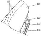
图6是表示构成提升器的第一构件的立体图。6 is a perspective view showing a first member constituting the lifter.
图7A是表示第二构件的凸出部插入于第一构件的安装孔的状态的图。7A is a view showing a state in which the protruding portion of the second member is inserted into the attachment hole of the first member.
图7B是表示第二构件的凸出部插入于第一构件的安装孔并进行结合的状态的图。7B is a view showing a state in which the protruding portion of the second member is inserted into the attachment hole of the first member and is coupled.
图7C是表示第二构件的凸出部插入于第一构件的安装孔之后使其弯曲的图。FIG. 7C is a view showing that the protruding portion of the second member is bent after being inserted into the mounting hole of the first member.
图8是表示提升器与滚筒相结合的状态的图。Fig. 8 is a view showing a state in which the lifter and the drum are coupled.
图9A是表示第一构件的挂钩部插入于滚筒的紧固孔的状态的图。9A is a view showing a state in which the hook portion of the first member is inserted into the fastening hole of the drum.
图9B是表示挂钩部进行滑动的状态的图。9B is a view showing a state in which the hook portion slides.
图9C是表示挂钩部在滑动后结合于滚筒的状态的图。9C is a view showing a state in which the hook portion is coupled to the drum after sliding.
图9D是表示从滚筒的外部观察提升器结合于滚筒内周面的状态时的状态的图。9D is a view showing a state in which the lifter is coupled to the inner peripheral surface of the drum as viewed from the outside of the drum.
图10是表示提升器结合于滚筒的内周面的状态和放大其的图。Fig. 10 is an enlarged view showing a state in which the lifter is coupled to the inner peripheral surface of the drum.
图11是从本体的前面部观察滚筒时的图。Fig. 11 is a view when the drum is viewed from the front part of the main body.
图12是表示在洗涤水流入到提升器的内部后,通过洗涤水排出孔向滚筒内部排出的状态的图。FIG. 12 is a view showing a state in which wash water is discharged into the drum through a wash water discharge hole after the wash water has flowed into the lifter.
具体实施方式Detailed ways
以下,参照附图更详细地说明本发明的拉伸实验用夹具。Hereinafter, the jig for a tensile test of the present invention will be described in more detail with reference to the accompanying drawings.
在本说明书中,即使是互不相同的实施例,对相同/相似的构成标注相同/相似的附图标记,并且其说明代替最初的说明。对于本说明书中所使用的单数而言,只要在文字上没有明确规定则包括复数。In this specification, the same/similar components are assigned the same/similar reference numerals even if the embodiments are different from each other, and the description thereof replaces the initial description. The singular used in this specification includes the plural unless it is explicitly stated in the text.
图1是表示衣物处理装置的整体结构的图。FIG. 1 is a diagram showing the overall configuration of a laundry treatment apparatus.
衣物处理装置包括:衣物处理装置本体11,其形成外壳;滚筒20,其可选转地安装在本体11的内部,并且用于投入洗涤物;提升器100,其设置于滚筒20的内部;门12,其设置于本体11的前面。在本体11的下部设置有覆盖用于投入洗涤剂的洗涤剂投入口的洗涤剂投入口盖体13。而且,为了对滚筒内部的洗涤物进行干燥,衣物处理装置在其内部包括用于循环空气的管道、热交换器等。The clothes treating apparatus includes: a clothes treating
通过在滚筒20的内周面22设置提升器100,在滚筒20进行旋转时,通过洗涤物的上升和下降帮助洗涤物的洗涤。提升器100是,在向滚筒20的内部投入洗涤剂、洗涤水以及洗涤物后,随着滚筒20的旋转,向上提起洗涤物并使其降落的同时帮助洗涤物的洗涤的装置。提升器100可以提供防止滚筒20内部的洗涤物缠绕,由此防止洗涤物损伤,并且可以减少水的使用量,而且拍打洗涤物并搓揉洗涤的效果。By providing the
图2是表示设置于滚筒20内周面22的提升器100的状态的图。FIG. 2 is a view showing a state of the
提升器100沿着与滚筒的旋转轴并行的方向延伸而形成,并且沿着滚筒本体21的内周面22设置。通常,提升器100在滚筒的内周面22设置多个,但是在提升器100以滚筒的旋转轴为基准非对称设置的情况下,随着滚筒的旋转会存在产生振动和噪音的忧虑,因此提升器100优选以滚筒的旋转轴为中心且以一定角度设置多个。The
图3是表示包括本发明所使用的滚筒和附着于滚筒的提升器100的滚筒内部结构的分解图。FIG. 3 is an exploded view showing the inner structure of the drum including the drum used in the present invention and the
滚筒包括平衡装置、滚筒前面构件26、滚筒本体21、提升器100、滚筒后面构件27、平衡装置25a、25b以及三角支架(spider)28,如图3所示,如果依次结合这些构件,则可具有图2所示的滚筒形状。对于构成The drum includes a balancing device, a drum front member 26, a
图3所示的滚筒的各个构件而言,平衡装置25a、25b是用于抑制因滚筒的旋转产生的振动的构件,十字轴28是起到向滚筒提供旋转力的作用的构件。如上所述,提升器100是起到在提起滚筒内部的洗涤物后使其降落的作用,并且起到通过落差提高洗涤性能的作用的构件。As for each member of the drum shown in FIG. 3, the balancer 25a, 25b is a member for suppressing the vibration which generate|occur|produces by rotation of a drum, and the cross shaft 28 is a member which provides a rotational force to a drum. As described above, the
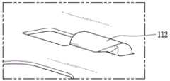
图4和图5是表示提升器100的结构的图。4 and 5 are diagrams showing the structure of the
如图4所示,提升器100由第一构件110和第二构件120相结合而形成,第二构件120设置在第一构件110上。提升器100可具有流线型或S字的形状,也可以具有以规定角度扭曲的非线性结构。据此,滚筒内的洗涤水随着滚筒的旋转通过提升器100更圆滑地流动。As shown in FIG. 4 , the
图5表示第二构件120结合在第一构件110上的状态。FIG. 5 shows a state in which the
首先,参照图5的下端部和图6说明第一构件110。在图5的下端部示出第一构件110的上面,在图6示出第一构件110的下面。第一构件110具备主体111、挂钩部112、遮挡部113、安装孔117、洗涤水流入孔115a以及螺丝插入孔119。First, the
第一构件的主体111形成第一构件110的整体结构,并且向与滚筒的旋转轴并行的方向延伸而形成,而且与滚筒的内周面22结合设置以保证与滚筒的旋转轴并行。The
第一构件110具备洗涤水流入部115。洗涤水流入部115形成为贯通第一构件110的孔,使得洗涤水流入至提升器100内。洗涤水流入部115与形成于滚筒的一部分孔重叠。The
洗涤水流入部115由多个洗涤水流入孔115a构成。如图5所示,各个洗涤水流入孔115a在与洗衣机滚筒的旋转轴并行的方向上互相隔开间隔而配置,并且具有贯通第一构件110的形状。The wash
在衣物处理装置的洗涤过程中,随着滚筒的旋转,洗涤水从洗涤槽流入至滚筒内,经由形成于滚筒的孔而流入的洗涤水,经过与形成于滚筒的孔重叠的各个洗涤水流入孔115a流入至提升器100的内部。During the washing process of the laundry treatment apparatus, as the drum rotates, wash water flows into the drum from the washing tub, and the wash water that flows through the holes formed in the drum flows into each wash water that overlaps the holes formed in the drum. The hole 115a flows into the inside of the
螺丝插入孔119形成在第一构件110的一侧,并起到用于固定在滚筒的作用。第一构件110可以通过螺丝插入孔119以螺纹连结的形式固定于滚筒的内侧面。如图5所示,螺丝插入孔119可以形成于第一构件110的两端,在第一构件110的洗涤水流入孔115a之间可以设置有多个。螺丝插入孔119具有可插入螺丝的普通形状。A
图6示出与滚筒内周面22相结合的第一构件110的后面。FIG. 6 shows the rear of the
从第一构件110的后面可知,第一构件110具备安装孔117、挂钩部112以及遮挡部113。As can be seen from the back of the
安装孔117用于使第一构件110和第二构件120相结合,第一构件110和第二构件120通过将第二构件120的凸出部123插入于安装孔117来相结合。如图7A所示,安装孔117沿着第一构件110的边缘部而形成,并具有可插入第二构件120的凸出部123的形状。安装孔117沿着第一构件110的边缘设置于多个位置。The mounting
挂钩部112沿着第一构件110下面的边缘凸出形成,并起到将第一构件110固定于滚筒的作用。如图6所示,挂钩部112具有挂钩形状,使得在插入后进行滑动而支撑于滚筒的一侧。The
挂钩部112在插入到位于滚筒的紧固孔24之后,进行滑动并支撑于滚筒的一侧,由此固定在滚筒。如图6所示,各个挂钩部112沿着第一构件110的边缘设置多个,可以互相面对设置。挂钩部112可以具有向第一构件110的中心部弯曲的形状。挂钩部112在插入于滚筒的紧固孔24之后向一个方向进行滑动,并配置成挂钩部112的至少一部分覆盖滚筒的内周面22。After the
遮挡部113向第一构件110的内侧凸出形成以覆盖紧固孔24。遮挡部113在挂钩部112插入于紧固孔24之后向一个方向进行滑动时起到完全覆盖紧固孔24的作用。遮挡部113沿着与滚筒的旋转方向相同的方向形成于第一构件110的一侧,由此防止洗涤水经由滚筒的紧固孔24流出。遮挡部113可以在第一构件110延伸的方向上沿着第一构件110一侧的边缘部互相隔开间隔地配置多个。The shielding
随着滚筒的旋转会产生离心力,由于覆盖紧固孔24的遮挡部113位于以滚筒的旋转方向为基准的相对较远的一侧,因此容纳于提升器100的洗涤水与滚筒的旋转无关地不会流出。即,从图6可以确认,遮挡部113只形成在以穿过椭圆形的第一构件110中心的长轴为基准的上侧。Centrifugal force is generated with the rotation of the drum, and since the shielding
在未设置有遮挡部113的第一构件110的另一侧,向第一构件110内侧凸出形成的挂钩部112在插入于紧固孔24之后向一个方向进行滑动,从而只覆盖滚筒的部分紧固孔24。如图6所示,当以第一构件110的长轴为基准时,在下面侧未形成有遮挡部113。由此,一部分洗涤水通过该部位流入至提升器100的内部。第一构件110可以由合成树脂形成,例如,On the other side of the
第一构件110可以由注塑的塑料形成。但是,并不限于该材料。The
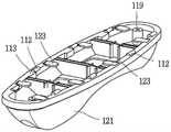
如图5所示,第二构件120包括主体121、凸出部123、洗涤水排出孔125。As shown in FIG. 5 , the
第二构件120的主体121向滚筒内部凸出形成,由此可以在内部空间容纳洗涤水。第二构件120的主体121具有非线性形状。The
凸出部123沿着主体121的下部边缘形成有多个。第二构件120的凸出部123插入于沿着第一构件110的边缘形成的安装孔117,由此第一构件110和第二构件120相结合。如图5所示,凸出部123形成于第二构件120的主体121的下部,并以从第二构件120的上部朝向下部的方式设置。A plurality of
为了排出从滚筒外部容纳于第二构件120的主体121中的洗涤水,洗涤水排出孔125设置于主体121的上部,并且沿着一个方向形成。具体而言,在第二构件120的主体121的上部形成有沿着一个方向延伸的第二构件的主体121上部面,在第二构件120的主体121上部面形成有多个洗涤水排出孔125。容纳于提升器100的洗涤水通过洗涤水排出孔125向滚筒排出,因此,可以起到帮助容纳于滚筒内部的洗涤物进行洗涤的作用。而且,通过提升器100向滚筒内部供水,由此可以减少洗涤过程中的水的使用量。In order to discharge the wash water accommodated in the
图7A至图7C示出构成提升器100的第一构件110和第二构件120相结合的过程。7A to 7C illustrate the process of combining the
图7A示出第二构件120的凸出部123插入于第一构件110的安装孔117的状态,并且形成于第二构件120的多个凸出部123在互相对应的位置插入于第一构件110的多个安装孔117,由此第一构件110和第二构件120相结合。7A shows a state in which the
图7B示出第二构件120的凸出部123插入于第一构件110的安装孔117,并且第一构件110位于上部,第二构件120位于下部的状态。图7B示出第二构件120的凸出部123插入于第一构件110的安装孔117并向上部凸出的状态。FIG. 7B shows a state in which the protruding
图7C示出为了固定插入于第一构件110安装孔117的第二构件120凸出部123,使凸出部123弯曲的状态。为了将第一构件110和第二构件120相结合,使插入于第一构件110的安装孔117并向上部凸出的第二构件120的凸出部123弯曲。凸出部123向第一构件110的内侧弯曲。7C shows a state in which the protruding
即,通过将第二构件120的凸出部123插入于第一构件110的安装孔117后进行弯曲,来使第一构件110和第二构件120相结合。That is, the
图8示出提升器100与滚筒相结合的状态。FIG. 8 shows a state in which the
在滚筒设置有用于固定提升器100的多个紧固孔24,提升器100的第一构件110的挂钩部112插入于滚筒的紧固孔24之后进行滑动,并且通过将螺丝与位于提升器100的第一构件的上下部的螺丝插入孔119连结,来可以使提升器100固定在滚筒。After the drum is provided with a plurality of fastening holes 24 for fixing the
图9A是表示第一构件110的挂钩部112插入于滚筒的紧固孔24的状态的图。为了使提升器100固定在滚筒,第一构件110的挂钩部112插入于滚筒的紧固孔24。9A is a view showing a state in which the
图9B是表示挂钩部112进行滑动的状态的图。第一构件110的挂钩部112在插入于滚筒的紧固孔24之后,向图中的箭头方向滑动。挂钩部112具有可以支撑滚筒的一侧的挂钩形状,挂钩部112通过滑动来支撑滚筒的一侧,由此可以更紧密地固定在滚筒。FIG. 9B is a diagram showing a state in which the
图9C示出挂钩部112在滑动后结合于滚筒的状态。如图9C所示,挂钩部112支撑滚筒本体21。具体而言,第一构件110的挂钩部112设置成覆盖滚筒的外周面和内周面的至少一部分。FIG. 9C shows a state in which the
图9D示出从滚筒的外部观察提升器100结合于滚筒的内周面22时的状态。如图9D所示,设置于第一构件110的各个挂钩部112支撑滚筒本体21的一部分,在左侧的紧固孔24存在第一构件110的遮挡部113。滚筒本体21与设置于第一构件110的螺丝插入孔119以螺纹连结进行固定,由此提升器100可以固定于滚筒内周面。FIG. 9D shows a state in which the
图10是表示提升器100结合于滚筒的内周面22的状态和放大其的图,右侧的放大图示出洗涤水可容纳于提升器100内部的结构,左侧的放大图示出容纳于提升器100内部的洗涤水没有向外部排出的结构。提升器100和滚筒通过第一构件110的挂钩部112的支撑和螺纹连结来互相结合。第一构件110的挂钩部112支撑滚筒的内周面22和外周面的一部分,并且通过将螺丝插入于第一构件110的螺丝插入孔119来与滚筒相结合。10 is an enlarged view showing a state in which the
如果第一构件110的各个挂钩部112在插入于滚筒的各个紧固孔24之后滑动,则第一构件110的遮挡部113覆盖滚筒的紧固孔24。遮挡部113在挂钩部112插入于紧固孔24之后向一个方向进行滑动时完全覆盖紧固孔24,从而防止洗涤水流出。椭圆形的第一构件110具有长轴,在以长轴为基准的左侧,通过第一构件110的遮挡部113完全覆盖紧固孔24。If each
从图10的左侧放大图可知,在挂钩部112的下端设置有遮挡部113,并覆盖滚筒的紧固孔24。遮挡部113沿着第一构件110一侧的边缘部向第一构件110内侧凸出形成,并且遮挡部113完全覆盖滚筒的紧固孔24,从而防止流入至提升器100内部的洗涤水经由滚筒的紧固孔24向外部流出。As can be seen from the left enlarged view of FIG. 10 , a shielding
图10的右侧放大图,示出滚筒的紧固孔24在以第一构件110的长轴为基准的右侧露出一部分的形状。在以穿过第一构件110中心的长轴为基准的右侧未形成有遮挡部113,因此,紧固孔24的一部分在未形成有遮挡部113的一侧向外部露出,从而部分洗涤水经由该部位流入至提升器100的内部。The right side enlarged view of FIG. 10 shows the shape in which a part of the fastening hole 24 of the drum is exposed on the right side based on the long axis of the
部分洗涤水沿着图10的箭头方向,通过与滚筒的孔不重叠的洗涤水流入孔115a、和因未设置有遮挡部113而一部分向外部露出的紧固孔24,来流入至提升器100的内部。Part of the wash water flows into the
图11是沿着图10的A线剖开的剖视图,是表示在洗涤水流入至提升器100内部之后经由洗涤水排出孔125向滚筒内部排出的状态的图。FIG. 11 is a cross-sectional view taken along line A of FIG. 10 , showing a state in which wash water is discharged into the drum through wash water discharge holes 125 after the wash water has flowed into the
如果滚筒进行旋转,则洗涤水通过围绕滚筒的洗涤槽流入至滚筒内部。部分洗涤水也会容纳于附着在滚筒内周面22的提升器100,并且洗涤水穿过滚筒的孔并经由与滚筒的孔重叠而成的第一构件110的洗涤水流入孔115a且穿过第二构件120的洗涤水排出孔125向滚筒的内部排出。而且,部分洗涤水也经由没有遮挡部113的紧固孔24而流入至提升器100的内部。图11的箭头表示洗涤水的移动方向。If the drum is rotated, the wash water flows into the inside of the drum through the washing tub surrounding the drum. Part of the wash water is also accommodated in the
图12是从本体的前面部观察滚筒时的图,并示出提升器100在滚筒内配置的状态。提升器100沿着滚筒的内周面22设置多个。如果提升器100不以滚筒的旋转轴为基准对称设置,则随着滚筒的旋转,会存在产生噪音和振动的忧虑,并且无法均匀地提起洗涤物,因此无法均匀地洗涤整体洗涤物。因此,如图12所示,提升器100优选以滚筒的旋转轴为基准对称设置多个。在该情况下,滚筒内的洗涤物挂在提升器100,由此可以在滚筒内有效地提升到规定高度,而且可以使滚筒内的洗涤水更圆滑地流动,从而可以提高洗涤效果。Fig. 12 is a view when the drum is viewed from the front part of the main body, and shows a state in which the
以上进行说明的衣物处理装置用提升器100并不限定于如上说明的实施例的结构和方法,可以以各种各样的变形构成。The
Claims (14)
Translated fromChineseApplications Claiming Priority (3)
| Application Number | Priority Date | Filing Date | Title |
|---|---|---|---|
| KR1020160001209AKR102449509B1 (en) | 2016-01-05 | 2016-01-05 | Lifter for clothes handling equipment |
| KR10-2016-0001209 | 2016-01-05 | ||
| CN201710006431.2ACN106939490B (en) | 2016-01-05 | 2017-01-05 | Lifter for laundry treatment device |
Related Parent Applications (1)
| Application Number | Title | Priority Date | Filing Date |
|---|---|---|---|
| CN201710006431.2ADivisionCN106939490B (en) | 2016-01-05 | 2017-01-05 | Lifter for laundry treatment device |
Publications (1)
| Publication Number | Publication Date |
|---|---|
| CN110820243Atrue CN110820243A (en) | 2020-02-21 |
Family
ID=57714548
Family Applications (6)
| Application Number | Title | Priority Date | Filing Date |
|---|---|---|---|
| CN201911267126.4AActiveCN111020979B (en) | 2016-01-05 | 2017-01-05 | Lifter for laundry treatment device |
| CN201911258571.4APendingCN110820243A (en) | 2016-01-05 | 2017-01-05 | Lifter for laundry treatment device |
| CN201710006431.2AActiveCN106939490B (en) | 2016-01-05 | 2017-01-05 | Lifter for laundry treatment device |
| CN201911258542.8APendingCN110820242A (en) | 2016-01-05 | 2017-01-05 | Lifter for laundry treatment device |
| CN201911267532.0AActiveCN110886064B (en) | 2016-01-05 | 2017-01-05 | Lifter for clothes processing device |
| CN201911259744.4AActiveCN110804840B (en) | 2016-01-05 | 2017-01-05 | Lifter for laundry treatment unit |
Family Applications Before (1)
| Application Number | Title | Priority Date | Filing Date |
|---|---|---|---|
| CN201911267126.4AActiveCN111020979B (en) | 2016-01-05 | 2017-01-05 | Lifter for laundry treatment device |
Family Applications After (4)
| Application Number | Title | Priority Date | Filing Date |
|---|---|---|---|
| CN201710006431.2AActiveCN106939490B (en) | 2016-01-05 | 2017-01-05 | Lifter for laundry treatment device |
| CN201911258542.8APendingCN110820242A (en) | 2016-01-05 | 2017-01-05 | Lifter for laundry treatment device |
| CN201911267532.0AActiveCN110886064B (en) | 2016-01-05 | 2017-01-05 | Lifter for clothes processing device |
| CN201911259744.4AActiveCN110804840B (en) | 2016-01-05 | 2017-01-05 | Lifter for laundry treatment unit |
Country Status (9)
| Country | Link |
|---|---|
| US (7) | US10633779B2 (en) |
| EP (5) | EP3581694A1 (en) |
| JP (5) | JP7071929B2 (en) |
| KR (1) | KR102449509B1 (en) |
| CN (6) | CN111020979B (en) |
| AU (10) | AU2016385265B2 (en) |
| DE (4) | DE202017007394U1 (en) |
| ES (1) | ES2763162T3 (en) |
| WO (1) | WO2017119591A1 (en) |
Cited By (1)
| Publication number | Priority date | Publication date | Assignee | Title |
|---|---|---|---|---|
| CN113355860A (en)* | 2020-03-06 | 2021-09-07 | Lg电子株式会社 | Laundry treatment apparatus |
Families Citing this family (27)
| Publication number | Priority date | Publication date | Assignee | Title |
|---|---|---|---|---|
| BR112014007727B1 (en) | 2011-10-07 | 2019-04-30 | The Procter & Gamble Company | Shampoo Composition and Process for Preparation |
| KR102449509B1 (en)* | 2016-01-05 | 2022-09-29 | 엘지전자 주식회사 | Lifter for clothes handling equipment |
| KR20190016863A (en)* | 2017-08-09 | 2019-02-19 | 엘지전자 주식회사 | Laundry Treating Apparatus |
| CN209292722U (en) | 2018-08-22 | 2019-08-23 | 无锡小天鹅电器有限公司 | Blender for roller washing machine and the roller washing machine with it |
| JP2021534897A (en)* | 2018-08-30 | 2021-12-16 | エルジー エレクトロニクス インコーポレイティドLg Electronics Inc. | Washing machine |
| KR102650116B1 (en)* | 2018-09-11 | 2024-03-21 | 삼성전자주식회사 | Drum type washing machine |
| KR20200096048A (en)* | 2019-02-01 | 2020-08-11 | 엘지전자 주식회사 | Laundry treating apparatus |
| EP3690108B1 (en)* | 2019-02-01 | 2021-05-12 | LG Electronics Inc. | Laundry treating apparatus |
| EP3690106B1 (en)* | 2019-02-01 | 2021-03-31 | LG Electronics Inc. | Laundry treating apparatus |
| KR20200096049A (en) | 2019-02-01 | 2020-08-11 | 엘지전자 주식회사 | Laundry treating apparatus |
| EP3690107A1 (en) | 2019-02-01 | 2020-08-05 | LG Electronics Inc. -1- | Laundry treating apparatus |
| KR102810496B1 (en)* | 2019-02-01 | 2025-05-23 | 엘지전자 주식회사 | Laundry treating apparatus |
| EP3690104B1 (en)* | 2019-02-01 | 2021-03-17 | LG Electronics Inc. | Laundry treating apparatus |
| EP3690109B1 (en)* | 2019-02-01 | 2021-05-05 | LG Electronics Inc. | Laundry treating apparatus |
| KR102789565B1 (en)* | 2019-02-01 | 2025-04-01 | 엘지전자 주식회사 | Laundry treating apparatus |
| EP3831998B1 (en) | 2019-02-01 | 2024-03-06 | LG Electronics Inc. | Laundry treating apparatus |
| EP3690110B1 (en) | 2019-02-01 | 2021-06-02 | LG Electronics Inc. | Laundry treating apparatus |
| TR201904343A2 (en)* | 2019-03-22 | 2020-10-21 | Arcelik As | A WASHING MACHINE WITH WINGS |
| CN112080898A (en)* | 2019-06-14 | 2020-12-15 | 青岛海尔智能技术研发有限公司 | Washing machine |
| KR20210063538A (en) | 2019-11-23 | 2021-06-02 | 임병우 | How the supply system for supply of goods in the fridge including RFID readers that can operate at low temperatures and RFID readers above |
| CN113106703B (en)* | 2020-01-09 | 2024-07-23 | 重庆海尔滚筒洗衣机有限公司 | Clothes lifting device for washing machine and drum washing machine |
| KR102491388B1 (en) | 2020-03-06 | 2023-01-20 | 엘지전자 주식회사 | Laundry treating apparatus |
| KR102491392B1 (en) | 2020-03-06 | 2023-01-27 | 엘지전자 주식회사 | Laundry treating apparatus |
| US12392079B2 (en) | 2021-02-08 | 2025-08-19 | Lg Electronics Inc. | Laundry treating apparatus |
| CN115142230A (en)* | 2021-03-31 | 2022-10-04 | 青岛海尔滚筒洗衣机有限公司 | Clothes lifting device for washing machine and washing machine |
| CN113584806A (en)* | 2021-07-28 | 2021-11-02 | 珠海格力电器股份有限公司 | Lifting rib of washing machine, roller washing machine and control method of lifting rib of washing machine |
| EP4502266A4 (en)* | 2022-03-31 | 2025-07-02 | Wuxi Little Swan Electric Co Ltd | INNER TUB OF A LAUNDRY TREATMENT APPLIANCE AND LAUNDRY TREATMENT APPLIANCE |
Citations (8)
| Publication number | Priority date | Publication date | Assignee | Title |
|---|---|---|---|---|
| DE1585867A1 (en)* | 1966-08-31 | 1971-10-07 | Philips Nv | Household washing machine |
| CN1414163A (en)* | 2001-10-23 | 2003-04-30 | Lg电子株式会社 | Washing machine |
| US20070017259A1 (en)* | 2005-06-30 | 2007-01-25 | Cho Han K | Drum type washer |
| CN1906349A (en)* | 2004-05-15 | 2007-01-31 | Lg电子株式会社 | Drum assembly for washing machine |
| KR100802467B1 (en)* | 2007-01-30 | 2008-02-13 | 삼성전자주식회사 | Drum washing machine |
| CN101316959A (en)* | 2005-12-02 | 2008-12-03 | Bsh博施及西门子家用器具有限公司 | laundry drum |
| CN103031694A (en)* | 2011-09-29 | 2013-04-10 | 三星电子株式会社 | Washing machine |
| KR20140084947A (en)* | 2012-12-27 | 2014-07-07 | 동부대우전자 주식회사 | Drum type washing machine |
Family Cites Families (38)
| Publication number | Priority date | Publication date | Assignee | Title |
|---|---|---|---|---|
| US1389182A (en) | 1920-03-31 | 1921-08-30 | Binder Gottlob | Rotary washing-machine |
| DE2310435A1 (en)* | 1973-02-28 | 1974-12-12 | Bosch Siemens Hausgeraete | Laundry washer or dryer drum - has plastics driver ribs each with floor part and V-shaped rib part |
| JPS54152333A (en) | 1978-05-19 | 1979-11-30 | Matsushita Electric Ind Co Ltd | Cooling, heating and hot water supplying device |
| JPS5669382U (en)* | 1979-10-31 | 1981-06-09 | ||
| DE3317201A1 (en)* | 1983-05-11 | 1984-11-15 | Licentia Patent-Verwaltungs-Gmbh, 6000 Frankfurt | Washing-machine drum |
| DE3642459C3 (en)* | 1986-12-12 | 1997-06-05 | Aeg Hausgeraete Gmbh | Laundry drum for a household appliance for drying laundry |
| DE8816711U1 (en)* | 1988-07-16 | 1990-04-12 | Henkel KGaA, 4000 Düsseldorf | Dosing memory |
| JPH06152174A (en)* | 1992-11-06 | 1994-05-31 | Fujitsu Ten Ltd | Structure for shielding electric circuit |
| KR100195453B1 (en)* | 1996-05-11 | 1999-06-15 | 윤종용 | Lifting device of drum washing machine |
| DE10259059B4 (en)* | 2002-12-17 | 2008-07-31 | BSH Bosch und Siemens Hausgeräte GmbH | Laundry drum for a drum washing machine |
| KR100465724B1 (en) | 2002-12-26 | 2005-01-13 | 엘지전자 주식회사 | Lift of drum washer |
| KR100889822B1 (en) | 2003-04-30 | 2009-03-20 | 삼성전자주식회사 | Drum Washing Machine |
| AU2004203379B2 (en)* | 2003-07-28 | 2006-10-12 | Lg Electronics Inc. | Washing machine |
| EP1529866A1 (en) | 2003-11-10 | 2005-05-11 | Samsung Electronics Co., Ltd. | Drum type washing machine |
| KR101041802B1 (en)* | 2004-04-22 | 2011-06-17 | 엘지전자 주식회사 | Drum washing machine |
| CN1779032A (en)* | 2004-11-19 | 2006-05-31 | 乐金电子(天津)电器有限公司 | Installation of lifter for drum washer |
| KR100627908B1 (en)* | 2005-05-26 | 2006-09-25 | 주식회사 대우일렉트로닉스 | Bin mounting structure of lifter for drum washing machine |
| KR100713946B1 (en)* | 2005-06-07 | 2007-05-07 | 삼성전자주식회사 | Drum Washing Machine |
| KR101208494B1 (en)* | 2005-06-30 | 2012-12-05 | 엘지전자 주식회사 | drum type washing machine |
| PL1849904T3 (en)* | 2006-04-27 | 2010-02-26 | Electrolux Home Products Corp Nv | Self-closing draining filter access apparatus for a top-loading washing machine |
| US20090276966A1 (en) | 2006-07-06 | 2009-11-12 | Bsh Bosch Und Siemens Hausgerate Gmbh | Washing machine with hollow agitators |
| KR100808204B1 (en) | 2007-04-10 | 2008-03-03 | 엘지전자 주식회사 | Drum Washing Machine |
| CN101668891A (en)* | 2007-05-14 | 2010-03-10 | 大宇电子株式会社 | washing machine having filtering lifters |
| ES2361860T3 (en) | 2007-10-19 | 2011-06-22 | Whirlpool Corporation | WASHER OR DRYER WITH A DRUM PROVIDED WITH MOVABLE ELEVATORS. |
| KR101520610B1 (en)* | 2008-09-25 | 2015-05-15 | 동부대우전자 주식회사 | Drum washing machine |
| CN101451297B (en)* | 2008-11-28 | 2013-03-13 | 上海墒抢环境技术有限公司 | Roll washing machine with circulation passage conforming to laundry powder use method |
| TWM384844U (en) | 2010-01-27 | 2010-07-21 | Qi-Rui Hong | Cup lid structure |
| KR20120082968A (en)* | 2011-01-16 | 2012-07-25 | 삼성전자주식회사 | Washing machine and pulsator thereof |
| CN103173961B (en)* | 2011-12-23 | 2016-04-06 | 青岛海日高科模型有限公司 | A kind of washing machine and washing methods |
| CN202509279U (en)* | 2012-02-22 | 2012-10-31 | 海尔集团公司 | Double-barrel washing machine provided with dismountable small washing barrel |
| KR102017530B1 (en)* | 2012-11-22 | 2019-09-04 | 삼성전자주식회사 | Lifter and drying machine having the same |
| KR20140084951A (en)* | 2012-12-27 | 2014-07-07 | 동부대우전자 주식회사 | Drum type washing machine |
| CN103114418B (en)* | 2013-02-26 | 2016-06-29 | 无锡小天鹅股份有限公司 | For the lifting muscle of washing machine, washing barrels component and the washing machine with it |
| KR102053143B1 (en)* | 2013-04-30 | 2019-12-06 | 엘지전자 주식회사 | A washing machine |
| US9458563B2 (en) | 2013-06-12 | 2016-10-04 | Alliance Laundry Systems Llc | Front loading washer baffle |
| KR102281197B1 (en) | 2016-01-05 | 2021-07-22 | 엘지전자 주식회사 | Lifter for laundary treating apparatus |
| KR102449509B1 (en) | 2016-01-05 | 2022-09-29 | 엘지전자 주식회사 | Lifter for clothes handling equipment |
| JP6910899B2 (en) | 2017-09-08 | 2021-07-28 | タイコエレクトロニクスジャパン合同会社 | Connector and connector assembly |
- 2016
- 2016-01-05KRKR1020160001209Apatent/KR102449509B1/enactiveActive
- 2016-11-08AUAU2016385265Apatent/AU2016385265B2/enactiveActive
- 2016-11-08JPJP2018554292Apatent/JP7071929B2/enactiveActive
- 2016-11-08WOPCT/KR2016/012808patent/WO2017119591A1/ennot_activeCeased
- 2017
- 2017-01-04DEDE202017007394.3Upatent/DE202017007394U1/enactiveActive
- 2017-01-04EPEP19185629.3Apatent/EP3581694A1/enactivePending
- 2017-01-04DEDE202017007395.1Upatent/DE202017007395U1/enactiveActive
- 2017-01-04EPEP17150288.3Apatent/EP3190220B1/enactiveActive
- 2017-01-04ESES17150288Tpatent/ES2763162T3/enactiveActive
- 2017-01-04EPEP19185636.8Apatent/EP3581695A1/enactivePending
- 2017-01-04EPEP19185631.9Apatent/EP3591113A1/enactivePending
- 2017-01-04DEDE202017007397.8Upatent/DE202017007397U1/enactiveActive
- 2017-01-04EPEP20169146.6Apatent/EP3712316A1/enactivePending
- 2017-01-04DEDE202017007393.5Upatent/DE202017007393U1/enactiveActive
- 2017-01-05USUS15/398,921patent/US10633779B2/enactiveActive
- 2017-01-05CNCN201911267126.4Apatent/CN111020979B/enactiveActive
- 2017-01-05CNCN201911258571.4Apatent/CN110820243A/enactivePending
- 2017-01-05CNCN201710006431.2Apatent/CN106939490B/enactiveActive
- 2017-01-05CNCN201911258542.8Apatent/CN110820242A/enactivePending
- 2017-01-05CNCN201911267532.0Apatent/CN110886064B/enactiveActive
- 2017-01-05CNCN201911259744.4Apatent/CN110804840B/enactiveActive
- 2019
- 2019-05-15JPJP2019091911Apatent/JP7086030B2/enactiveActive
- 2019-05-15JPJP2019091915Apatent/JP7084893B2/enactiveActive
- 2019-05-15JPJP2019091916Apatent/JP7086031B2/enactiveActive
- 2019-05-24USUS16/422,626patent/US11319655B2/enactiveActive
- 2019-05-24USUS16/422,573patent/US11401645B2/enactiveActive
- 2019-05-24USUS16/422,724patent/US11384469B2/enactiveActive
- 2019-07-19AUAU2019206108Apatent/AU2019206108A1/ennot_activeAbandoned
- 2019-07-19AUAU2019206107Apatent/AU2019206107B2/enactiveActive
- 2019-07-19AUAU2019206106Apatent/AU2019206106B2/enactiveActive
- 2020
- 2020-02-24AUAU2020201332Apatent/AU2020201332B2/enactiveActive
- 2020-03-06USUS16/811,486patent/US11982038B2/enactiveActive
- 2020-03-30JPJP2020060118Apatent/JP7118103B2/enactiveActive
- 2020-11-30AUAU2020103804Apatent/AU2020103804B4/ennot_activeExpired
- 2020-11-30AUAU2020103800Apatent/AU2020103800A4/ennot_activeCeased
- 2020-11-30AUAU2020103802Apatent/AU2020103802B4/ennot_activeExpired
- 2020-11-30AUAU2020103798Apatent/AU2020103798A4/ennot_activeCeased
- 2021
- 2021-05-05AUAU2021202854Apatent/AU2021202854C1/enactiveActive
- 2022
- 2022-01-14USUS17/576,171patent/US11603617B2/enactiveActive
- 2024
- 2024-04-08USUS18/629,108patent/US12416113B2/enactiveActive
Patent Citations (8)
| Publication number | Priority date | Publication date | Assignee | Title |
|---|---|---|---|---|
| DE1585867A1 (en)* | 1966-08-31 | 1971-10-07 | Philips Nv | Household washing machine |
| CN1414163A (en)* | 2001-10-23 | 2003-04-30 | Lg电子株式会社 | Washing machine |
| CN1906349A (en)* | 2004-05-15 | 2007-01-31 | Lg电子株式会社 | Drum assembly for washing machine |
| US20070017259A1 (en)* | 2005-06-30 | 2007-01-25 | Cho Han K | Drum type washer |
| CN101316959A (en)* | 2005-12-02 | 2008-12-03 | Bsh博施及西门子家用器具有限公司 | laundry drum |
| KR100802467B1 (en)* | 2007-01-30 | 2008-02-13 | 삼성전자주식회사 | Drum washing machine |
| CN103031694A (en)* | 2011-09-29 | 2013-04-10 | 三星电子株式会社 | Washing machine |
| KR20140084947A (en)* | 2012-12-27 | 2014-07-07 | 동부대우전자 주식회사 | Drum type washing machine |
Cited By (4)
| Publication number | Priority date | Publication date | Assignee | Title |
|---|---|---|---|---|
| CN113355860A (en)* | 2020-03-06 | 2021-09-07 | Lg电子株式会社 | Laundry treatment apparatus |
| US11674254B2 (en) | 2020-03-06 | 2023-06-13 | Lg Electronics Inc. | Laundry treating apparatus |
| CN113355860B (en)* | 2020-03-06 | 2023-09-08 | Lg电子株式会社 | Laundry treatment apparatus |
| US12012687B2 (en) | 2020-03-06 | 2024-06-18 | Lg Electronics Inc. | Laundry treating apparatus |
Also Published As
Similar Documents
| Publication | Publication Date | Title |
|---|---|---|
| CN106939490B (en) | Lifter for laundry treatment device | |
| KR102281197B1 (en) | Lifter for laundary treating apparatus | |
| KR102281195B1 (en) | Lifter for laundary treating apparatus | |
| KR102283888B1 (en) | Lifter for laundary treating apparatus | |
| KR102281193B1 (en) | Lifter for laundary treating apparatus |
Legal Events
| Date | Code | Title | Description |
|---|---|---|---|
| PB01 | Publication | ||
| PB01 | Publication | ||
| SE01 | Entry into force of request for substantive examination | ||
| SE01 | Entry into force of request for substantive examination |