CN110811711A - a retractor - Google Patents
a retractorDownload PDFInfo
- Publication number
- CN110811711A CN110811711ACN201911115231.6ACN201911115231ACN110811711ACN 110811711 ACN110811711 ACN 110811711ACN 201911115231 ACN201911115231 ACN 201911115231ACN 110811711 ACN110811711 ACN 110811711A
- Authority
- CN
- China
- Prior art keywords
- fixing shell
- tissue
- shell
- retracting
- clamping
- Prior art date
- Legal status (The legal status is an assumption and is not a legal conclusion. Google has not performed a legal analysis and makes no representation as to the accuracy of the status listed.)
- Pending
Links
Images


Classifications
- A—HUMAN NECESSITIES
- A61—MEDICAL OR VETERINARY SCIENCE; HYGIENE
- A61B—DIAGNOSIS; SURGERY; IDENTIFICATION
- A61B17/00—Surgical instruments, devices or methods
- A61B17/02—Surgical instruments, devices or methods for holding wounds open, e.g. retractors; Tractors
- A61B17/0218—Surgical instruments, devices or methods for holding wounds open, e.g. retractors; Tractors for minimally invasive surgery
- A—HUMAN NECESSITIES
- A61—MEDICAL OR VETERINARY SCIENCE; HYGIENE
- A61B—DIAGNOSIS; SURGERY; IDENTIFICATION
- A61B17/00—Surgical instruments, devices or methods
- A61B17/02—Surgical instruments, devices or methods for holding wounds open, e.g. retractors; Tractors
- A61B17/0281—Abdominal wall lifters
- A—HUMAN NECESSITIES
- A61—MEDICAL OR VETERINARY SCIENCE; HYGIENE
- A61B—DIAGNOSIS; SURGERY; IDENTIFICATION
- A61B17/00—Surgical instruments, devices or methods
- A61B17/02—Surgical instruments, devices or methods for holding wounds open, e.g. retractors; Tractors
- A61B2017/0287—Surgical instruments, devices or methods for holding wounds open, e.g. retractors; Tractors with elastic retracting members connectable to a frame, e.g. hooked elastic wires
Landscapes
- Health & Medical Sciences (AREA)
- Life Sciences & Earth Sciences (AREA)
- Surgery (AREA)
- Heart & Thoracic Surgery (AREA)
- Engineering & Computer Science (AREA)
- Biomedical Technology (AREA)
- Nuclear Medicine, Radiotherapy & Molecular Imaging (AREA)
- Medical Informatics (AREA)
- Molecular Biology (AREA)
- Animal Behavior & Ethology (AREA)
- General Health & Medical Sciences (AREA)
- Public Health (AREA)
- Veterinary Medicine (AREA)
- Surgical Instruments (AREA)
Abstract
Translated fromChinese
Description
Translated fromChinese技术领域technical field
本发明涉及微创手术器械技术领,具体涉及一种牵开固定器。The invention relates to the technical field of minimally invasive surgical instruments, in particular to a retractor fixer.
背景技术Background technique
微创手术,顾名思义就是微小创伤的手术。是指利用腹腔镜、胸腔镜等现代医疗器械及相关设备进行的手术。微创手术的优点是创伤小、疼痛轻、恢复快是每个需要手术的病人的梦想,微创外科使这个梦想成为了现实。Minimally invasive surgery, as the name suggests, is surgery with minimal trauma. Refers to the use of laparoscopes, thoracoscopes and other modern medical equipment and related equipment for surgery. The advantages of minimally invasive surgery are that less trauma, less pain, and faster recovery are the dreams of every patient who needs surgery. Minimally invasive surgery has made this dream a reality.
现有的微创手术器械多种多样,基本都是需要医生从人体体外进行操作,如手术剪、抓钳等。这些手术器械在使用的时候都需要医生进行操作,有时候,在进行手术的时候,病人腹腔内的组织器官等会遮挡或覆盖住需要针对的部位,此时则需要医生再利用现有的器械工具进行翻开、支撑,这样极大程度妨碍了手术的进行,拖延了手术的时间,无形中增加了手术的风险。There are various types of existing minimally invasive surgical instruments, which basically require doctors to operate from outside the human body, such as surgical scissors, grasping forceps, etc. These surgical instruments need to be operated by a doctor. Sometimes, during the operation, the tissues and organs in the patient's abdominal cavity will block or cover the parts that need to be targeted. At this time, the doctor needs to reuse the existing instruments. The tools are opened and supported, which greatly hinders the operation, delays the operation time, and virtually increases the risk of the operation.
发明内容SUMMARY OF THE INVENTION
针对现有技术的不足,本发明提供一种牵开固定器,能在微创手术的过程中,在患者腹腔内对组织器官进行夹持,从而将组织器官拉至不妨碍医生手术视野的地方,从而加速手术的进行。In view of the deficiencies of the prior art, the present invention provides a retractor fixator, which can clamp tissues and organs in the abdominal cavity of a patient during minimally invasive surgery, so as to pull the tissues and organs to a place that does not obstruct the doctor's surgical field of vision , thereby speeding up the operation.
为实现上述目的,本发明的技术方案为:For achieving the above object, the technical scheme of the present invention is:
一种牵开固定器,包括用于夹持在患者腹腔壁上的牵开夹和用于夹持组织器官的组织夹,所述牵开夹与组织夹通过钢丝相连,所述组织夹包括长条形的组织夹固定壳以及沿组织夹固定壳长度向方向滑动连接的第一联动件,所述第一联动件与组织夹固定壳之间设有第一复位弹性件,所述组织夹固定壳上铰接有夹头,所述夹头与组织夹固定壳配合实现夹持组织器官的功能,所述第一联动件与组织夹固定壳发生相对滑动时驱使夹头开合,第一复位弹性件处于自然状态下时,夹头处于夹持状态,所述牵开夹包括长条形的牵开夹固定壳以及沿牵开夹固定壳长度向方向滑动连接的第二联动件,所述第二联动件与牵开夹固定壳之间设有第二复位弹性件,所述牵开夹固定壳上设置有夹持组件,所述第二联动件与牵开夹固定壳发生相对滑动时驱使夹持组件开合,第二复位弹性件处于自然状态下时,夹持组件处于夹持状态。A retraction fixator, comprising a retraction clip for clamping on the abdominal cavity wall of a patient and a tissue clip for clamping tissues and organs, the retraction clip and the tissue clip are connected with a steel wire, and the tissue clip includes a long A strip-shaped tissue clip fixing shell and a first linkage member slidably connected along the length of the tissue clip fixing shell, a first reset elastic member is arranged between the first linkage member and the tissue clip fixing shell, and the tissue clip is fixed A collet is hinged on the shell, and the collet cooperates with the tissue clip fixing shell to realize the function of clamping tissues and organs. When the clip is in a natural state, the collet is in a clamping state, and the retraction clip includes an elongated retraction clip fixing shell and a second linkage member slidably connected along the length of the retraction clip fixing shell. A second reset elastic member is arranged between the two linkage members and the fixing shell of the retraction clip, and a clamping assembly is arranged on the fixing shell of the retraction clip. When the clamping assembly is opened and closed, and the second restoring elastic member is in a natural state, the clamping assembly is in a clamping state.
进一步地,所述夹头长度不小于组织夹固定壳长度的1/2,所述夹头上沿其铰接位置径向方向设置有斜面,所述第一联动件上凸设有与斜面配合的驱动块,通过驱动块与斜面的配合以及第一联动件与组织夹固定壳之间的配合实现夹头的开合。Further, the length of the collet is not less than 1/2 of the length of the fixed shell of the tissue clip, the collet is provided with an inclined surface along the radial direction of its hinge position, and the first linkage is protruded with a bevel that cooperates with the inclined surface. The driving block realizes the opening and closing of the collet through the cooperation between the driving block and the inclined surface and the cooperation between the first linkage member and the fixing shell of the tissue clip.
进一步地,所述组织夹固定壳形状为圆柱形,其一端凸设有一圈第一凸边,所述组织夹固定壳上开设有贯穿其侧壁的第一通槽,所述夹头铰接位置在第一通槽处,所述组织夹固定壳的一端开设有连通至第一通槽的供第一联动件滑动的第一开槽,所述第一联动件伸入组织夹固定壳的一端沿第一通槽的方向凸设有第一卡块,所述第一卡块伸出组织夹固定壳,所述第一复位弹性件的一端与第一卡块相抵,另一端与第一凸边相抵。Further, the tissue clip fixing shell is cylindrical in shape, one end of which is protruded with a circle of first protruding edges, the tissue clip fixing shell is provided with a first through groove penetrating its side wall, and the clip is hinged at the position. At the first through slot, one end of the tissue clip fixing shell is provided with a first slot connected to the first through slot for the first link member to slide, and the first link member extends into one end of the tissue clip fixing shell A first blocking block protrudes along the direction of the first through groove, the first blocking block protrudes from the tissue clip fixing shell, one end of the first reset elastic member is in contact with the first blocking block, and the other end is in contact with the first blocking block. Edges meet.
进一步地,所述夹持组件包括两个转动连接在牵开夹固定壳一端的夹块,所述夹块上开设有滑槽,所述第二联动件上凸设有与滑槽配合的滑块,通过滑槽与滑块的配合以及第二联动件与牵开夹固定壳之间的配合实现夹块的开合。Further, the clamping assembly includes two clamping blocks that are rotatably connected to one end of the fixing shell of the retraction clamp, the clamping blocks are provided with sliding grooves, and the second linkage member is protrudingly provided with sliding sliding grooves matched with the sliding grooves. The clamping block is opened and closed through the cooperation between the sliding groove and the sliding block and the cooperation between the second linkage and the fixing shell of the retraction clamp.
进一步地,所述牵开夹固定壳形状为圆柱形,其一端凸设有一圈第二凸边,所述牵开夹固定壳上开设有贯穿其侧壁的第二通槽,所述牵开夹固定壳的一端开设有连通至第二通槽的供第二联动件滑动的第二开槽,所述第二联动件伸入牵开夹固定壳的一端沿第二通槽的方向凸设有两个第二卡块,所述第二卡块伸出牵开夹固定壳,所述第二复位弹性件的一端与第二卡块相抵,另一端与第二凸边相抵,所述第二卡块向靠近夹块的方向延伸并与夹块连接。Further, the shape of the retraction clip fixing shell is cylindrical, and one end of the retraction clip fixing shell is protruded with a second convex edge, and the retraction clip fixing shell is provided with a second through groove running through its side wall. One end of the clip fixing shell is provided with a second slot connected to the second through groove for the second linkage member to slide, and one end of the second linkage member extending into the retraction clip fixing shell is protruded along the direction of the second through slot There are two second blocks, the second blocks extend out of the retraction clip fixing shell, one end of the second reset elastic piece is in contact with the second block, and the other end is in contact with the second convex edge, the first The two clamping blocks extend toward the direction close to the clamping block and are connected with the clamping block.
进一步地,所述第一联动件远离组织夹固定壳的一端设置有第一拉钩,所述第二联动件远离牵开夹固定壳的一端设置有第二拉钩。Further, one end of the first linkage member away from the fixing shell of the tissue clip is provided with a first hook, and one end of the second linkage member away from the fixing shell of the retractor clip is provided with a second hook.
本发明与现有技术相比,具有如下优点:Compared with the prior art, the present invention has the following advantages:
本发明通过牵开夹夹持在腹腔壁上,然后利用组织夹将组织器官夹持,利用牵开夹与组织夹之间固定的连接距离将组织器官夹持并拉开,从而有利于医生进行手术。同时两者均为圆柱形结构,从而能更好地从Trocar孔送入人体腹腔内进行夹持工作,并加设有拉钩,更便于医生在使用的时候拉动牵开夹和组织夹进行使用。In the present invention, the retraction clips are clamped on the abdominal cavity wall, then the tissue clamps are used to clamp the tissues and organs, and the fixed connection distance between the retraction clamps and the tissue clamps is used to clamp and pull apart the tissues and organs, thereby facilitating doctors to perform Operation. At the same time, both of them are cylindrical structures, so that they can be better sent from the Trocar hole into the abdominal cavity of the human body for clamping work, and a retractor is added, which is more convenient for doctors to pull the retractor clip and tissue clip for use.
附图说明Description of drawings
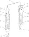
图1为牵开固定器的整体结构示意图;1 is a schematic diagram of the overall structure of the retractor;
图2为牵开固定器的组织夹侧面结构示意图;Fig. 2 is the side structure schematic diagram of the tissue clip of the retractor fixator;
图3为图2中A-A部分剖面结构示意图;Fig. 3 is a schematic diagram of the cross-sectional structure of part A-A in Fig. 2;
图4为牵开固定器的牵开夹结构示意图;Figure 4 is a schematic view of the retraction clip structure of the retractor fixator;
图5为牵开固定器的牵开夹剖面结构示意图;Fig. 5 is the sectional structure schematic diagram of the retraction clip of the retractor fixer;
附图标记说明:1、组织夹;11、组织夹固定壳;111、第一通槽;112、第一开槽;113、第一凸边;12、第一联动件;121、驱动块;122、第一卡块;13、第一复位弹性件;14、夹头;15、第一拉钩;2、牵开夹;21、牵开夹固定壳;211、第二通槽;212、第二开槽;213、第二凸边;22、第二联动件;221、第二卡块;23、第二复位弹性件;24、夹持组件;241、夹块;242、滑块;243、滑槽;25、第二拉钩;3、钢丝。Description of reference numerals: 1, tissue clip; 11, tissue clip fixing shell; 111, first through groove; 112, first slot; 113, first raised edge; 12, first linkage; 122, the first block; 13, the first reset elastic member; 14, the collet; 15, the first hook; 2, the retraction clip; 21, the retraction clip fixing shell; 211, the second through groove; 2. Slotting; 213, the second convex edge; 22, the second linkage; 221, the second block; 23, the second reset elastic part; 24, the clamping assembly; 241, the clamping block; 242, the slider; 243 , Chute; 25, the second hook; 3, steel wire.
具体实施方式Detailed ways
为使本发明的上述目的、特征和优点能够更加明显易懂,下面结合附图和具体实施方式对本发明作进一步详细的说明。In order to make the above objects, features and advantages of the present invention more clearly understood, the present invention will be described in further detail below with reference to the accompanying drawings and specific embodiments.
实施例Example
如图1所示,一种牵开固定器,包括用于夹持在患者腹腔壁上的牵开夹2和用于夹持组织器官的组织夹1,牵开夹2与组织夹1通过钢丝3相连,为了避免钢丝3在生产的过程中出现倒刺等缺陷,还可在钢丝3上套有一层医用软胶管。如图2和图3所示,组织夹1包括圆柱形的组织夹固定壳11以及沿组织夹固定壳11长度向方向滑动连接的第一联动件12,第一联动件12与组织夹固定壳11之间设有第一复位弹性件13,组织夹固定壳11上铰接有夹头14,夹头14与组织夹固定壳11配合实现夹持组织器官的功能,第一联动件12与组织夹固定壳11发生相对滑动时驱使夹头14开合,第一复位弹性件13处于自然状态下时,夹头14处于夹持状态。As shown in Fig. 1, a retraction fixator includes a
如图3所示,组织夹固定壳11的一端凸设有一圈第一凸边113,组织夹固定壳11上开设有贯穿其侧壁的第一通槽111,夹头14的铰接位置在第一通槽111处,组织夹固定壳11的一端开设有连通至第一通槽111的供第一联动件12滑动的第一开槽112,第一联动件12伸入组织夹固定壳11的一端沿第一通槽111的方向凸设有两个第一卡块122,第一卡块122伸出组织夹固定壳11,第一复位弹性件13可以为弹簧等具有弹性的物件,在本实施例中为弹簧,第一复位弹性件13的一端与第一卡块122相抵,另一端与第一凸边113相抵,以实现第一联动件12与组织夹固定壳11发生相对滑移的时候,复位至夹头14处于夹持的状态的位置。As shown in FIG. 3 , one end of the tissue
夹头14的形状为弓状,为了使组织夹1能稳定地夹住较大的组织器官,因此夹头14的整体长度应不小于组织夹固定壳11长度的1/2,夹头14上沿其铰接位置的径向方向设置有斜面,第一联动件12上凸设有与斜面配合的驱动块121,斜面的方向为从上往下向第一通槽111的内部倾斜,当第一联动件12向下滑动的时候,驱动块121则会与斜面配合,将夹头14向外顶开;松开第一联动件12的时候,则在第一复位弹性的作用下,第一联动组件回复到初始位置,同时夹头14在第一复位弹性件13的作用下回复到夹持状态。The shape of the
如图4和图5所示,牵开夹2包括圆柱形的牵开夹固定壳21以及沿牵开夹固定壳21长度向方向滑动连接的第二联动件22,第二联动件22与牵开夹固定壳21之间设有第二复位弹性件23,牵开夹固定壳21上设置有夹持组件24,第二联动件22与牵开夹固定壳21发生相对滑动时驱使夹持组件24开合,第二复位弹性件23处于自然状态下时,夹持组件24处于夹持状态。As shown in FIGS. 4 and 5 , the
如图5所示,牵开夹固定壳21的一端凸设有一圈第二凸边213,牵开夹固定壳21上开设有贯穿其侧壁的第二通槽211,牵开夹固定壳21的一端开设有连通至第二通槽211的供第二联动件22滑动的第二开槽212,第二联动件22伸入牵开夹固定壳21的一端沿第二通槽211的方向凸设有两个第二卡块221,第二卡块221伸出牵开夹固定壳21,第二复位弹性件23与第一复位弹性件13相似,可为弹簧,其一端与第二卡块221相抵,另一端与第二凸边213相抵,第二卡块221向靠近夹块241的方向延伸并与夹块241连接。夹持组件24包括两个转动连接在牵开夹固定壳21一端的夹块241,夹块241的形状结构可依据调整,可为平面的块状结构,亦可为钩状结构等。夹块241上开设有滑槽243,第二联动件22上凸设有与滑槽243配合的滑块242,通过滑槽243与滑块242的配合以及第二联动件22与牵开夹固定壳21之间的滑动实现夹块241的开合。As shown in FIG. 5 , one end of the retraction
当第二联动件22与牵开夹固定壳21之间发生相对滑动的时候,由于夹块241与牵开夹固定壳21为铰接,因此在滑块242与滑槽243的配合下,夹块241会随着第二联动件22的滑动而有相应的开合动作,达到联动的效果。When there is relative sliding between the
此处为了尽量缩小牵开夹2与组织夹1的最大宽度,将第一联动件12与夹头14均设置在组织夹固定壳11的内部,将第二联动件22与牵开夹固定壳21做成类似同轴的设置,以能更好地从Trocar孔送入人体内。同时为了能更好地在人体内进行操作,第一联动件12远离组织夹固定壳11的一端设置有第一拉钩15,第二联动件22远离牵开夹固定壳21的一端设置有第二拉钩25,利用拉钩能更好地实现固定壳与联动件之间的相对滑动。In order to reduce the maximum width of the
具体地在使用的时候,首先将本发明的牵开固定器全部送入人体腹腔内,然后先利用工具拉动第一联动件12,使组织夹1夹持着需要牵开的组织器官,之后再拉动第二联动件22,使牵开夹2的夹持组件24打开,根据需要的距离等夹持在患者的腹腔壁上,达到扩展手术视野目的。最后在使用完后只需先后拉动第一联动件12与第二联动件22,便可松开,之后只需将本发明的牵开固定器取出即可。Specifically, when in use, first all the retraction fixator of the present invention is sent into the abdominal cavity of the human body, and then the
上述实施例只是为了说明本发明的技术构思及特点,其目的是在于让本领域内的普通技术人员能够了解本发明的内容并据以实施,并不能以此限制本发明的保护范围。凡是根据本发明内容的实质所做出的等效的变化或修饰,都应涵盖在本发明的保护范围内。The above-mentioned embodiments are only to illustrate the technical concept and characteristics of the present invention, and the purpose thereof is to enable those of ordinary skill in the art to understand the content of the present invention and implement them accordingly, and not to limit the protection scope of the present invention. All equivalent changes or modifications made according to the essence of the present invention shall be included within the protection scope of the present invention.
Claims (6)
Priority Applications (1)
| Application Number | Priority Date | Filing Date | Title |
|---|---|---|---|
| CN201911115231.6ACN110811711A (en) | 2019-11-14 | 2019-11-14 | a retractor |
Applications Claiming Priority (1)
| Application Number | Priority Date | Filing Date | Title |
|---|---|---|---|
| CN201911115231.6ACN110811711A (en) | 2019-11-14 | 2019-11-14 | a retractor |
Publications (1)
| Publication Number | Publication Date |
|---|---|
| CN110811711Atrue CN110811711A (en) | 2020-02-21 |
Family
ID=69555243
Family Applications (1)
| Application Number | Title | Priority Date | Filing Date |
|---|---|---|---|
| CN201911115231.6APendingCN110811711A (en) | 2019-11-14 | 2019-11-14 | a retractor |
Country Status (1)
| Country | Link |
|---|---|
| CN (1) | CN110811711A (en) |
Cited By (1)
| Publication number | Priority date | Publication date | Assignee | Title |
|---|---|---|---|---|
| CN112790802A (en)* | 2021-02-03 | 2021-05-14 | 中山大学附属第三医院(中山大学肝脏病医院) | Cavity Organ Retractor |
Citations (7)
| Publication number | Priority date | Publication date | Assignee | Title |
|---|---|---|---|---|
| US20090222029A1 (en)* | 2006-10-03 | 2009-09-03 | Udi Gordin | Clip for assisting surgical procedures |
| WO2009147669A1 (en)* | 2008-06-03 | 2009-12-10 | Virtual Ports Ltd. | A multi-components device, system and method for assisting minimally invasive procedures |
| US20130237768A1 (en)* | 2010-07-05 | 2013-09-12 | Virtual Ports Ltd. | Internal retractor |
| CN107510482A (en)* | 2016-06-16 | 2017-12-26 | 微至(苏州)医疗科技有限公司 | Disposable tissue retraction folder |
| KR20190078070A (en)* | 2017-12-26 | 2019-07-04 | 연세대학교 산학협력단 | Retractor of organ for laparocopic surgery |
| CN209074718U (en)* | 2018-03-28 | 2019-07-09 | 毛张凡 | Intracavitary traction device |
| CN211409195U (en)* | 2019-11-14 | 2020-09-04 | 路鹏 | Retractor fixator |
- 2019
- 2019-11-14CNCN201911115231.6Apatent/CN110811711A/enactivePending
Patent Citations (8)
| Publication number | Priority date | Publication date | Assignee | Title |
|---|---|---|---|---|
| US20090222029A1 (en)* | 2006-10-03 | 2009-09-03 | Udi Gordin | Clip for assisting surgical procedures |
| US20090250081A1 (en)* | 2006-10-03 | 2009-10-08 | Udi Gordin | Device and method for lens cleaning for surgical procedures |
| WO2009147669A1 (en)* | 2008-06-03 | 2009-12-10 | Virtual Ports Ltd. | A multi-components device, system and method for assisting minimally invasive procedures |
| US20130237768A1 (en)* | 2010-07-05 | 2013-09-12 | Virtual Ports Ltd. | Internal retractor |
| CN107510482A (en)* | 2016-06-16 | 2017-12-26 | 微至(苏州)医疗科技有限公司 | Disposable tissue retraction folder |
| KR20190078070A (en)* | 2017-12-26 | 2019-07-04 | 연세대학교 산학협력단 | Retractor of organ for laparocopic surgery |
| CN209074718U (en)* | 2018-03-28 | 2019-07-09 | 毛张凡 | Intracavitary traction device |
| CN211409195U (en)* | 2019-11-14 | 2020-09-04 | 路鹏 | Retractor fixator |
Cited By (2)
| Publication number | Priority date | Publication date | Assignee | Title |
|---|---|---|---|---|
| CN112790802A (en)* | 2021-02-03 | 2021-05-14 | 中山大学附属第三医院(中山大学肝脏病医院) | Cavity Organ Retractor |
| CN112790802B (en)* | 2021-02-03 | 2025-05-09 | 中山大学附属第三医院(中山大学肝脏病医院) | Cavity organ traction device |
Similar Documents
| Publication | Publication Date | Title |
|---|---|---|
| US11026696B2 (en) | Endoscopic clip applier | |
| ES2706744T3 (en) | Hemostatic forceps | |
| US8986326B2 (en) | Gasper and grasping tool | |
| US12336711B2 (en) | Wide hemostasis clip | |
| CN105266858B (en) | For guiding the method and apparatus of suture | |
| CN112451052B (en) | Breast tumor resection device | |
| CN211409195U (en) | Retractor fixator | |
| CN206355086U (en) | Draw tissue fixator in a kind of art | |
| CN110811711A (en) | a retractor | |
| CN107693059B (en) | A kind of operation device fixed for internal organs in Minimally Invasive Surgery | |
| CN107510482A (en) | Disposable tissue retraction folder | |
| CN211704713U (en) | Fixed retractor | |
| CN205054307U (en) | Minimally Invasive Scalp Retractor | |
| CN205163206U (en) | Get thing pincers through vagina | |
| CN110811712A (en) | a fixed retractor | |
| CN216394150U (en) | Traction equipment for brain tissue operation | |
| CN212415841U (en) | placenta grasping forceps | |
| CN211534543U (en) | Biopsy extractor in uterine cavity | |
| CN204562254U (en) | Medical stapler | |
| CN209529229U (en) | Hooking needle assembly | |
| CN111358517A (en) | A portable operation type suture needle holder suitable for small incision wide-angle and deep operation | |
| CN208784899U (en) | Rib rongeur set for thoracoscopy | |
| CN106264666B (en) | A kind of connectionless elastic separating plier | |
| CN204890108U (en) | Spermatic duct nipper for peritoneoscope | |
| CN220385106U (en) | Multi-functional sample under chamber mirror gets thing bag |
Legal Events
| Date | Code | Title | Description |
|---|---|---|---|
| PB01 | Publication | ||
| PB01 | Publication | ||
| SE01 | Entry into force of request for substantive examination | ||
| SE01 | Entry into force of request for substantive examination | ||
| RJ01 | Rejection of invention patent application after publication | ||
| RJ01 | Rejection of invention patent application after publication | Application publication date:20200221 |