CN110811065A - Manufacturing method and structure of automatic shoe last - Google Patents
Manufacturing method and structure of automatic shoe lastDownload PDFInfo
- Publication number
- CN110811065A CN110811065ACN201810901330.6ACN201810901330ACN110811065ACN 110811065 ACN110811065 ACN 110811065ACN 201810901330 ACN201810901330 ACN 201810901330ACN 110811065 ACN110811065 ACN 110811065A
- Authority
- CN
- China
- Prior art keywords
- automated
- clamping
- shoe
- shoe last
- base material
- Prior art date
- Legal status (The legal status is an assumption and is not a legal conclusion. Google has not performed a legal analysis and makes no representation as to the accuracy of the status listed.)
- Withdrawn
Links
- 238000004519manufacturing processMethods0.000titleclaimsabstractdescription42
- 238000012545processingMethods0.000claimsabstractdescription63
- 238000000034methodMethods0.000claimsabstractdescription31
- 239000000758substrateSubstances0.000claimsabstractdescription8
- 239000000463materialSubstances0.000claimsdescription38
- 230000008569processEffects0.000claimsdescription19
- 229920001903high density polyethylenePolymers0.000claimsdescription6
- 239000004700high-density polyethyleneSubstances0.000claimsdescription6
- 238000003801millingMethods0.000claimsdescription6
- 238000002347injectionMethods0.000claimsdescription4
- 239000007924injectionSubstances0.000claimsdescription4
- 238000005553drillingMethods0.000claimsdescription3
- 238000007493shaping processMethods0.000claimsdescription3
- 230000000694effectsEffects0.000abstractdescription8
- 210000001161mammalian embryoAnatomy0.000description25
- 238000010586diagramMethods0.000description8
- 238000013461designMethods0.000description4
- 230000002950deficientEffects0.000description3
- 238000011161developmentMethods0.000description3
- 238000005516engineering processMethods0.000description3
- 229920003023plasticPolymers0.000description3
- 239000004033plasticSubstances0.000description3
- 238000004026adhesive bondingMethods0.000description2
- 239000000203mixtureSubstances0.000description2
- 238000000465mouldingMethods0.000description2
- 239000004698PolyethyleneSubstances0.000description1
- 230000008859changeEffects0.000description1
- 238000006073displacement reactionMethods0.000description1
- 239000011121hardwoodSubstances0.000description1
- 238000003754machiningMethods0.000description1
- 239000002184metalSubstances0.000description1
- 238000012986modificationMethods0.000description1
- 230000004048modificationEffects0.000description1
- -1polyethylenePolymers0.000description1
- 229920000573polyethylenePolymers0.000description1
- 229920000642polymerPolymers0.000description1
- 230000004044responseEffects0.000description1
- 230000000007visual effectEffects0.000description1
- 239000002023woodSubstances0.000description1
Images


Classifications
- A—HUMAN NECESSITIES
- A43—FOOTWEAR
- A43D—MACHINES, TOOLS, EQUIPMENT OR METHODS FOR MANUFACTURING OR REPAIRING FOOTWEAR
- A43D3/00—Lasts
- A43D3/02—Lasts for making or repairing shoes
- B—PERFORMING OPERATIONS; TRANSPORTING
- B26—HAND CUTTING TOOLS; CUTTING; SEVERING
- B26F—PERFORATING; PUNCHING; CUTTING-OUT; STAMPING-OUT; SEVERING BY MEANS OTHER THAN CUTTING
- B26F1/00—Perforating; Punching; Cutting-out; Stamping-out; Apparatus therefor
- B26F1/16—Perforating by tool or tools of the drill type
Landscapes
- Life Sciences & Earth Sciences (AREA)
- Forests & Forestry (AREA)
- Engineering & Computer Science (AREA)
- Mechanical Engineering (AREA)
- Footwear And Its Accessory, Manufacturing Method And Apparatuses (AREA)
Abstract
Translated fromChinese
Description
Translated fromChinese技术领域technical field
本发明是有关于一种自动化鞋楦制作方法及其结构,尤指一种能提供与自动化工艺相互融合贯接的鞋楦制作方法,使其达成一致化精准加工程序的功效。The present invention relates to an automatic shoe last manufacturing method and its structure, in particular to a shoe last manufacturing method that can be integrated and connected with an automatic process, so as to achieve the effect of a consistent and precise processing procedure.
背景技术Background technique
鞋楦主要是一种用来决定鞋子尺寸大小的制鞋模具;换言之,鞋楦不只是鞋子的母体,更是鞋子的成型模具,所以,鞋楦设计必须以使用者的脚型与尺寸作为基础,方能制作出符合脚部实际尺寸需求的合脚鞋子。The shoe last is mainly a shoe-making mold used to determine the size of the shoe; in other words, the shoe last is not only the mother of the shoe, but also the molding mold of the shoe. Therefore, the shoe last design must be based on the user's foot shape and size. , in order to make shoes that fit the actual size of the foot.
一般鞋楦以材质分为有木、塑料和金属三种。传统鞋楦是采用质地坚硬、密度高、纹理细致的硬木树材所制成,而随着科技的发展,以及个人化消费意识的抬头,演变成大量鞋类产品的需求与供应下,传统以人工或机械加工生产木制鞋楦方式,势必已经无法满足现今鞋业产品需求量高的生产要求。也因如此,木制鞋楦逐渐被HDPE(高密度聚乙烯)为材料的塑料鞋楦取代,而成为现代制鞋工业用鞋楦的主要类型;塑料鞋楦主要以高密度聚乙烯注塑成鞋楦毛坯,然后使用专用鞋楦机铣切加工而成所需鞋形曲线的鞋楦。Generally, shoe lasts are divided into three types: wood, plastic and metal. Traditional shoe lasts are made of hardwood trees with hard texture, high density and fine texture. With the development of technology and the rise of personal consumption awareness, it has evolved into the demand and supply of a large number of footwear products. The production of wooden shoe lasts by manual or mechanical processing is bound to be unable to meet the production requirements of today's high demand for footwear products. Because of this, wooden shoe lasts are gradually replaced by plastic shoe lasts made of HDPE (high density polyethylene), and become the main type of shoe lasts used in the modern shoe industry; plastic shoe lasts are mainly injection molded into shoes with high density polyethylene. The last blank is then milled with a special shoe last machine to form the shoe last with the desired shoe shape curve.
而上述专用鞋楦机的加工程序为将鞋楦毛坯架设于机台内,并于鞋楦毛坯两端分别定位夹固,使其定位的两端形成一轴线,而能转动鞋楦毛坯,再让加工器具由边侧导入,而对应鞋楦毛坯进行加工粗、细、精铣切加工,使其完成所需鞋楦造形,但加工完成后的鞋楦两端(即鞋尖与鞋后踵部位)残留夹固定位的毛坯料,故需要以人工再进一次修整毛边坯料的加工;由此可知,在传统鞋楦加工过程,步骤较为繁杂且无法自动化完成,导致工艺工时等成本上昂,实已成为相关技术领域业者所急欲解决与挑战的技术课题。The processing procedure of the above-mentioned special shoe last machine is that the shoe last blank is erected in the machine table, and the two ends of the shoe last blank are respectively positioned and clamped, so that the two ends of the positioning form an axis, and the shoe last blank can be rotated, and then the shoe last blank can be rotated. Let the processing equipment be imported from the side, and the corresponding shoe last blank is processed by rough, fine, and fine milling to complete the required shoe last shape. position) the remaining clip is fixed in position, so it is necessary to manually trim the burr blank again; it can be seen that in the traditional shoe last processing process, the steps are more complicated and cannot be completed automatically, resulting in high costs such as process man-hours, etc. In fact, it has become a technical issue that the industry in related technical fields is eager to solve and challenge.
然而,自动化在各产业都已慢慢成为发展趋势,过去以手工为主的传统制鞋业,现在也有自动化公司开发出能自动制鞋的机械,像是通过3D视觉路径生成,不需标准化的产品也能进行制作,在鞋子的客制化上,也能有更高的效率。基于未来鞋品将朝向少量多样生产的趋势,因此,需要有一套以自动化机械手臂来抓取鞋楦以进行多工艺站点的自动化加工控制制鞋生产设备;也因如此,为了提供自动化机械手臂来抓取鞋楦进行制鞋,其在鞋楦上需安装有供机械手臂夹取的夹座;而夹座需锁入定位于上述经专用鞋楦机加工后的鞋楦端面上,需于端面钻设锁孔,如中国台湾专利公告第M526300号“自动化多功能鞋楦专用夹治具”,再将夹座通过锁孔而固定;但是钻设锁孔的技术需要非常精准,若有些偏差则会导致每一鞋楦上的夹座位置均不相同,当夹座供机械手臂夹取之后,进入自动化加工过程中,而在加工过程主要以夹座位置为基准,让鞋楦与加工治具和工具间呈现三度空间的对应关系,若因每一鞋楦的夹座都有些许偏差,导致每一鞋楦相对加工治具和工具的定位会有所误差,会产生定位不精确的移位缺失,使其不良率居高不下的严重后果。However, automation has gradually become a development trend in various industries. In the past, the traditional shoemaking industry was mainly manual, and now there are automation companies that have developed machines that can automatically make shoes, such as through 3D visual path generation, without standardized The product can also be produced, and the customization of shoes can also be more efficient. Based on the trend of shoe production in the future, there will be a small amount of diverse production. Therefore, there is a need for a set of automatic processing and control shoe production equipment that uses an automated robotic arm to grab shoe lasts for multi-process stations. Grab the shoe last to make shoes, and the shoe last needs to be installed with a clamp seat for the mechanical arm to clamp; and the clamp seat needs to be locked and positioned on the end surface of the shoe last machined by the special shoe last, and it needs to be drilled on the end surface. Set a keyhole, such as Taiwan Patent Bulletin No. M526300 "Automated Multifunctional Shoe Last Special Fixture", and then fix the clamp seat through the keyhole; however, the technology of drilling the keyhole needs to be very precise, if there is some deviation, it will be As a result, the position of the clamp seat on each shoe last is different. After the clamp seat is clamped by the robotic arm, it enters the automatic processing process. There is a three-dimensional correspondence between the tools. If the clamping seat of each shoe last has a slight deviation, the positioning of each shoe last relative to the processing jig and tool will be wrong, resulting in inaccurate positioning displacement. Missing, the serious consequences of its high non-performing rate.
现在,发明人秉持多年该相关行业的丰富设计开发及实际制作经验,针对现有专用鞋楦机于制作鞋楦时的工艺缺失及鞋楦组装夹座的准确性问题再予以研究改进,提供一种自动化鞋楦制作方法及其结构,以期达到更佳实用价值性的目的。Now, the inventor, adhering to the rich experience in design, development and actual production in the related industry for many years, has studied and improved the existing special shoe last machine for the lack of craftsmanship and the accuracy of the shoe last assembly clamp seat, and provides a new An automatic shoe last manufacturing method and structure thereof are provided in order to achieve the purpose of better practical value.
发明内容SUMMARY OF THE INVENTION
本发明的目的在于提供一种自动化鞋楦制作方法及其结构,尤其是指一种能提供与自动化工艺相互融合贯接的鞋楦制作方法,使其达成一致化精准加工程序的功效。The purpose of the present invention is to provide an automatic shoe last manufacturing method and structure thereof, especially a shoe last manufacturing method that can be integrated and connected with the automatic process, so as to achieve the effect of a consistent and precise processing procedure.
为达到上述目的,本发明提供一种自动化鞋楦制作方法,其于一胚体基材的端面上对应锁固并定位一夹座,所述夹座能通过自动化加工设备的夹头夹取,并以所述夹座作为加工基准对所述胚体基材的外部表面进行铣削加工,完成一鞋楦本体造形;借此,让制成后的鞋楦能更符合于自动化制鞋程序且尺寸精确无误,达到规格一致化、零损坏率的功效。In order to achieve the above-mentioned purpose, the present invention provides an automatic shoe last manufacturing method, wherein a clamping seat is correspondingly locked and positioned on the end face of a base material of an embryo body, and the clamping seat can be clamped by a chuck of an automatic processing equipment, And the outer surface of the base material of the embryo body is milled with the clamping seat as a machining reference to complete the shape of a shoe last body; thereby, the finished shoe last can be more in line with the automatic shoe-making procedure and the size Accurate and accurate, achieving the effect of consistent specifications and zero damage rate.
本发明还提供一种自动化鞋楦制作方法,其具体步骤为:The present invention also provides an automated shoe last manufacturing method, the specific steps of which are:
(a)、胚体基材:取一胚体基材,于所述胚体基材上设有一组设端面及相邻所述组设端面的至少一侧面,再于所述组设端面上钻设有多个锁孔,及于所述侧面对应所述锁孔处钻设定位孔,且该定位孔与该锁孔相互交会,再于所述定位孔内置入锁固件;(a), embryo body base material: take an embryo body base material, set a set of end faces and at least one side surface adjacent to the set end face on the base body of the base body, and then set the set end face on the set end face. A plurality of locking holes are drilled, and a setting hole is drilled at the side corresponding to the locking hole, and the positioning hole and the locking hole intersect each other, and then a locking member is built into the positioning hole;
(b)、定位夹座:备设一表面具有夹道的夹座,所述夹座对应所述锁孔处设有穿孔,所述穿孔供螺杆穿设,且所述螺杆通过所述锁孔而锁入于所述锁固件,以将所述夹座定位于所述胚体基材的组设端面;(b) Positioning clip seat: a clip seat with a clip channel on one surface of the equipment, the clip seat is provided with a perforation corresponding to the lock hole, the perforation is used for the screw to pass through, and the screw rod passes through the lock hole. be locked into the fastener, so as to locate the clip seat on the assembly end face of the base material of the embryonic body;
(c)、夹取加工:经由一自动化加工设备的夹头对应所述夹座的夹道而夹取所述胚体基材进入加工设备中,并以所述夹座作为加工基准对所述胚体基材的外部表面进行铣削加工,完成一鞋楦本体造形。(c) Clamping processing: The embryo base material is clamped into the processing equipment through the chuck of an automatic processing equipment corresponding to the clamping channel of the clamping seat, and the embryo is processed by using the clamping seat as a processing reference. The outer surface of the body base material is milled to complete the shape of a shoe last body.
本发明的自动化鞋楦制作方法的较佳实施例,其中详细工艺经由:a)胚体基材、b)定位夹座、c)夹取加工等步骤,制成一符合自动化制鞋程序且尺寸精确无误的鞋楦。A preferred embodiment of the automatic shoe last manufacturing method of the present invention, wherein the detailed process is made through the steps of: a) the base material of the embryo body, b) the positioning of the clamping seat, and c) the clamping process, etc. An unmistakable last.
本发明的自动化鞋楦制作方法的较佳实施例,其中所述胚体基材为采高密度聚乙烯所注制而成。A preferred embodiment of the automatic shoe last manufacturing method of the present invention, wherein the base material of the embryo body is made of high-density polyethylene by injection.
本发明的自动化鞋楦制作方法的较佳实施例,其中所述自动化加工设备为自动化多轴加工机。A preferred embodiment of the automatic shoe last manufacturing method of the present invention, wherein the automatic processing equipment is an automatic multi-axis processing machine.
本发明的自动化鞋楦制作方法的较佳实施例,其中所述自动化鞋楦制作方法进一步包含有步骤(d)、自动化生产:将步骤(c)所加工完成的所述鞋楦本体导入自动化工艺进行(如塑鞋形、上胶、整帮等等)制鞋加工。A preferred embodiment of the automated shoe last manufacturing method of the present invention, wherein the automated shoe last manufacturing method further comprises step (d), automated production: introducing the shoe last body processed in step (c) into an automated process Carry out (such as shoe shaping, gluing, whole ganging, etc.) shoemaking process.
本发明还提供了一种自动化鞋楦结构,其由上述自动化鞋楦制作方法制成,所述自动化鞋楦结构包含有一鞋楦本体,为一由胚体基材经自动化加工设备铣削加工的鞋楦,所述鞋楦本体具有一组设端面,于所述组设端面设有两锁孔,并于所述鞋楦本体的与两所述锁孔的垂直向分别钻设定位孔,且所述定位孔与所述锁孔相互交会;两锁固件,分别对应嵌组于两所述定位孔,所述锁固件设有内螺纹,且所述内螺纹对应所述锁孔;一夹座,对应组设于所述鞋楦本体的组设端面,所述夹座的表面设有供所述自动化加工设备的夹头夹取的夹道,且所述夹座对应所述组设端面的两所述锁孔处分别设有穿孔;两螺杆,分别对应穿过所述夹座的穿孔并穿入所述锁孔,且所述螺杆锁设于所述锁固件的内螺纹。The present invention also provides an automatic shoe last structure, which is made by the above-mentioned automatic shoe last manufacturing method. The automatic shoe last structure includes a shoe last body, which is a shoe last made of a base material of an embryo body and processed by automatic processing equipment. Last, the shoe last body has a set of end faces, two lock holes are arranged on the set end faces, and setting holes are respectively drilled in the vertical direction of the shoe last body and the two lock holes, and The positioning hole and the locking hole intersect each other; two locking members are respectively embedded in the two positioning holes, the locking member is provided with an inner thread, and the inner thread corresponds to the locking hole; a clamping seat , correspondingly assembled on the assembly end face of the shoe last body, the surface of the clamp base is provided with a clamp channel for the chuck of the automated processing equipment to be clamped, and the clamp base corresponds to the two end faces of the assembly end face. The locking holes are respectively provided with perforations; two screw rods respectively pass through the perforations of the clamping base and penetrate into the locking holes, and the screw rods are locked on the inner thread of the locking member.
本发明的自动化鞋楦制作方法的较佳实施例,其中所述锁固件能为圆形体、方形体和六角形体中的一种。In a preferred embodiment of the automatic shoe last manufacturing method of the present invention, the fastener can be one of a circular body, a square body and a hexagonal body.
通过以上所述,由本发明系统的组成与使用实施说明可知,本发明与现有结构相较之下,具有下列优点:Through the above, it can be seen from the composition and use implementation description of the system of the present invention that the present invention has the following advantages compared with the existing structure:
1.本发明的自动化鞋楦制作方法及其结构,经由自动化加工设备所制成的鞋楦,不需经二次加工,且每一鞋楦的尺寸、角度和曲度都相同,故不会产生误差的不良品。1. automatic shoe last manufacturing method of the present invention and structure thereof, the shoe last made by automatic processing equipment does not need to be processed twice, and the size, angle and curvature of each shoe last are the same, so it will not be Defective products with errors.
2.本发明的自动化鞋楦制作方法及其结构,经由自动化加工设备所制成的鞋楦,能更符合于自动化制鞋程序且尺寸精确无误,达到规格一致化、零损坏率的功效。2. The automatic shoe last manufacturing method of the present invention and its structure, the shoe last made by the automatic processing equipment can be more in line with the automatic shoe-making procedure and the size is accurate, achieving the effects of uniform specification and zero damage rate.
附图说明Description of drawings
以下附图仅旨在于对本发明做示意性说明和解释,并不限定本发明的范围。其中:The following drawings are only intended to illustrate and explain the present invention schematically, and do not limit the scope of the present invention. in:
图1:本发明的方块示意图;Fig. 1: block schematic diagram of the present invention;
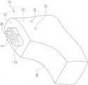
图2:本发明的步骤c示意图;Fig. 2: step c schematic diagram of the present invention;
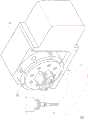
图3:本发明的自动化加工设备进行铣削加工示意图一;Fig. 3: The automatic processing equipment of the present invention performs milling processing schematic diagram 1;
图4:本发明的自动化加工设备进行铣削加工示意图二;Fig. 4: The automatic processing equipment of the present invention performs milling processing schematic diagram II;
图5:本发明的自动化加工设备进行铣削加工示意图三;Fig. 5: schematic diagram three of the automatic processing equipment of the present invention for milling;
图6:本发明的鞋楦完成示意图;Fig. 6: the shoe last of the present invention is completed schematic diagram;
图7:本发明的鞋楦剖视示意图。Figure 7: A schematic sectional view of the shoe last of the present invention.
附图标号说明:Description of reference numbers:
1 鞋楦本体1 Last body
10 胚体基材10 embryo body substrate
11 组设端面11 sets of end faces
12 侧面12 sides
13 锁孔13 Keyhole
14 定位孔14 Locating holes
2 夹座2 clips
21 夹道21 Passage
22 穿孔22 perforation
3 自动化加工设备3 Automatic processing equipment
31 夹头31 collet
4 锁固件4 Lock firmware
41 内螺纹41 Internal thread
5 螺杆5 Screws
步骤a 胚体基材Step a: Embryo Substrate
步骤b 定位夹座Step b Position the clip seat
步骤c 夹取加工Step c gripping processing
步骤d 自动化生产Step d Automated production
具体实施方式Detailed ways
为令本发明所运用的技术内容、发明目的及其达成的功效有更完整且清楚的揭露,现于下详细说明,并请一并参阅所揭的附图及图号:For a more complete and clear disclosure of the technical content, the purpose of the invention and the effect achieved by the present invention, the following detailed description is now given, and please refer to the disclosed drawings and drawing numbers together:
首先,本发明实际运用技术与手段,请参阅图1~图2所示,为本发明的自动化鞋楦制作方法及其结构的方块与步骤示意图,其主要于一胚体基材10的端面上对应锁固并定位一夹座2,所述夹座2通过一自动化加工设备3的夹头31夹取,并以夹座2为基准对所述胚体基材10的外部表面进行铣削加工,完成一鞋楦本体1造形。First, the practical application techniques and means of the present invention, please refer to FIG. 1 to FIG. 2 , which are block diagrams and step schematic diagrams of the automatic shoe last manufacturing method and its structure of the present invention, which are mainly applied to the end surface of an embryonic body base material 10 A
经由上述的制作方式,将其详细工艺的顺序分述如下(如图1、图7所示),其步骤为:Through the above-mentioned manufacturing method, the order of its detailed process is described as follows (as shown in Figure 1 and Figure 7), and the steps are:
a、胚体基材-取一经由高密度聚乙烯所注制的胚体基材10,于所述胚体基材10上设有一组设端面11及相邻组设端面的至少一侧面12,再于所述组设端面11上钻设有多个锁孔13,及于胚体基材的一侧面对应所述锁孔13处钻设与该锁孔13相互交会的定位孔14,再于所述定位孔14内置入锁固件4;a. Base material of embryo body - take a base material of
b、定位夹座-备设一表面具有夹道21的夹座2,所述夹座2对应所述锁孔13处设有穿孔22,穿孔22供螺杆5穿设,且螺杆5通过所述锁孔13而锁入于锁固件4,以定位所述夹座2;b. Positioning clip seat - a
c、夹取加工-经由一自动化加工设备3的夹头31对应所述夹座2的夹道21处夹取所述胚体基材10进入自动化加工设备3中,并以夹座2为基准对所述胚体基材10的外部表面进行铣削加工,完成一鞋楦本体1造形(请参图3~图6所示)。c. Clamping processing - through the
当实际实施时,请参图1~图6、图7所示,经由步骤a、胚体基材,先取得一胚体基材10,所述胚体基材10为采用高密度聚合物所制成,如聚乙烯所注制而成的胚体基材10,而所述胚体基材10的外观形状如一矩形体或略呈鞋形粗胚的块状物,注制的所述胚体基材10形成有一组设端面11及相邻组设端面的至少一侧面12;之后,于所述胚体基材10的组设端面11上钻设有锁孔13,而锁孔13数量为依据锁固夹座2的大小、长度形状而评估,基本上需至少设有两锁孔13,再于其中一侧面12对应所述锁孔13处钻设与锁孔13相互交会的定位孔14,于各所述定位孔14内分别嵌设置入锁固件4,让所述锁固件4位于所述定位孔14与所述锁孔13的交会处,所述锁固件4具有能与螺杆5锁固的内螺纹41。When actually implemented, please refer to FIGS. 1 to 6 and 7, through step a, the embryonic body substrate, firstly obtain an
接着,执行步骤b、定位夹座,准备一表面具有夹道21的夹座2,所述夹道21的设计为因应自动化加工设备3的夹头31而作变化,并不局限为特定形状的夹道21,进一步于所述夹座2对应所述锁孔13处设有穿孔22,所述穿孔22供螺杆5穿设,让螺杆5穿过穿孔22并通过所述锁孔13而锁入于锁固件4的内螺纹41,如此,能将所述夹座2定位于所述胚体基材10的组设端面11。然而,在自动化加工过程无论是胚体加工或是后续制鞋加工过程,所述胚体基材10受夹头31夹固后的运动路径为360度的任意角度旋转(依鞋型设计而变化),故所述胚体基材10所受的作用力,除了夹座2的垂直向之外,更有旋转所带来的横向受力;因此,本发明中的所述胚体基材10具有纵向打出的锁孔13和横向打入的定位孔14,且锁孔13与定位孔14交会,利用纵向穿入锁孔13的螺杆5锁固于横向定位孔14内的锁固件4产生直向的锁固力,并由直向锁固力所延伸的拉力,将锁固件4紧迫于定位孔14缘,达到将夹座2纵横双向固定的功用,以能符合运动路径的变化。Next, perform step b, locating the clamping base, and prepare a
接续,通过步骤c、夹取加工,将安装有所述夹座2的所述胚体基材10经由一自动化加工设备3的夹头31来对应所述夹座2的夹道21而夹取,使所述胚体基材10被安装定位于自动化加工设备3中,而所述自动化加工设备3进一步为自动化多轴加工机(如五轴、四加一轴、四轴或三轴等等加工机),于启动加工时,让所述自动化加工设备3的加工基础点以所述夹座2为准则,并使得所述胚体基材10被旋转任一方向加工时,因所述夹座2与所述胚体基材10经由纵横双向固定,而具有稳固、稳定性效用,当所述胚体基材10的外部表面通过自动化加工设备3进行铣削加工后,能完成一鞋楦本体1造形,且每一胚体基材10铣削成鞋楦本体1的加工过程准确无误。Continuing, through step c, the clamping process, the
由上述的制作过程可知,能获得一自动化鞋楦结构,请参图7所示,自动化鞋楦结构包含有:It can be known from the above-mentioned production process that an automated shoe last structure can be obtained. Please refer to Figure 7. The automated shoe last structure includes:
一鞋楦本体1,为一由胚体基材10经自动化加工设备3铣削加工的鞋楦,其具有一组设端面11,于所述组设端面11设有两锁孔13,并于鞋楦本体1的与两所述锁孔13的垂直向分别钻设定位孔14,且定位孔14与锁孔13相互交会;A shoe
两锁固件4,分别对应嵌组于两所述定位孔14,所述锁固件4设有内螺纹41,且所述内螺纹41对应所述锁孔13;The two
一夹座2,对应组设于所述鞋楦本体1的组设端面11,所述夹座2的表面设有供自动化加工设备3的夹头31夹取的夹道21,且所述夹座2对应所述组设端面11的两所述锁孔13处分别设有穿孔22;A
两螺杆5,分别对应穿过所述夹座2的穿孔22并穿入所述锁孔13,且螺杆5锁设于所述锁固件4的内螺纹41。The two
于实施时,所述锁固件4嵌入横向的定位孔14内,锁固件4主要供纵向穿入锁孔13的螺杆5锁固,当于螺杆5锁入横向锁固件4时产生直向的锁固力,于锁固过程的拉力将锁固件4紧迫于定位孔14缘,因此,所述锁固件4对应所述螺杆5的端面须承受作用力,为了考虑受力问题,所述锁固件4可为如图所示的圆形体,或可承受较大作用力的方形体、六角形体等等,或其他任意形体;当然,所述定位孔14的孔状随所述锁固件4而作变化。During implementation, the locking
经由上述的方法来进行自动化鞋楦制作,而所制成获得的鞋楦本体1因每一胚体基材10均以所述夹座2作为加工基准,所制作出的鞋楦本体1的造形和尺寸相同,不会有角度和曲度误差;当完成后的每一鞋楦能经由步骤d、自动化生产步骤,将步骤c所加工完成的鞋楦本体导入自动化制程工艺进行制鞋加工,当进入自动化工艺时如塑鞋形、上胶、整帮等等加工时,因夹座2不变、基准不变且鞋楦尺寸、角度和曲度都相同,故不会产生误差的不良品。通过以上所述,由本发明系统的组成与使用实施说明可知,本发明与现有结构相较之下,具有下列优点:Through the above-mentioned method to carry out automatic shoe last production, and the obtained shoe
1.本发明的自动化鞋楦制作方法及其结构,经由自动化加工设备所制成的鞋楦,不需经二次加工,且每一鞋楦的尺寸、角度和曲度都相同,故不会产生误差的不良品。1. automatic shoe last manufacturing method of the present invention and structure thereof, the shoe last made by automatic processing equipment does not need to be processed twice, and the size, angle and curvature of each shoe last are the same, so it will not be Defective products with errors.
2.本发明的自动化鞋楦制作方法及其结构,经由自动化加工设备所制成的鞋楦,能更符合于自动化制鞋程序且尺寸精确无误,达到规格一致化、零损坏率的功效。2. The automatic shoe last manufacturing method of the present invention and its structure, the shoe last made by the automatic processing equipment can be more in line with the automatic shoe-making procedure and the size is accurate, achieving the effects of uniform specification and zero damage rate.
以上所述仅为本发明示意性的具体实施方式,并非用以限定本发明的范围。任何本领域的技术人员,在不脱离本发明的构思和原则的前提下所作出的等同变化与修改,均应属于本发明保护的范围。而且需要说明的是,本发明的各组成部分并不仅限于上述整体应用,本发明的说明书中描述的各技术特征可以根据实际需要选择一项单独采用或选择多项组合起来使用,因此,本发明理所当然地涵盖了与本案发明点有关的其它组合及具体应用。The above descriptions are only exemplary embodiments of the present invention, and are not intended to limit the scope of the present invention. Equivalent changes and modifications made by any person skilled in the art without departing from the concept and principles of the present invention shall fall within the protection scope of the present invention. Moreover, it should be noted that each component of the present invention is not limited to the above-mentioned overall application, and each technical feature described in the specification of the present invention can be used alone or in combination according to actual needs. Therefore, the present invention Of course, other combinations and specific applications related to the inventive point of the present application are covered.
Claims (9)
Priority Applications (1)
| Application Number | Priority Date | Filing Date | Title |
|---|---|---|---|
| CN201810901330.6ACN110811065A (en) | 2018-08-09 | 2018-08-09 | Manufacturing method and structure of automatic shoe last |
Applications Claiming Priority (1)
| Application Number | Priority Date | Filing Date | Title |
|---|---|---|---|
| CN201810901330.6ACN110811065A (en) | 2018-08-09 | 2018-08-09 | Manufacturing method and structure of automatic shoe last |
Publications (1)
| Publication Number | Publication Date |
|---|---|
| CN110811065Atrue CN110811065A (en) | 2020-02-21 |
Family
ID=69540870
Family Applications (1)
| Application Number | Title | Priority Date | Filing Date |
|---|---|---|---|
| CN201810901330.6AWithdrawnCN110811065A (en) | 2018-08-09 | 2018-08-09 | Manufacturing method and structure of automatic shoe last |
Country Status (1)
| Country | Link |
|---|---|
| CN (1) | CN110811065A (en) |
Citations (5)
| Publication number | Priority date | Publication date | Assignee | Title |
|---|---|---|---|---|
| US4741062A (en)* | 1985-09-06 | 1988-05-03 | Roger Blanc | Last for automated shoe manufacture |
| TW201228814A (en)* | 2011-01-12 | 2012-07-16 | Ming-Te Chen | Adjustable shoe mold set |
| WO2016196129A1 (en)* | 2015-05-31 | 2016-12-08 | Nike Innovate C.V. | Shoe last extension as an origin |
| CN207011808U (en)* | 2017-04-19 | 2018-02-16 | 耐克创新有限合伙公司 | Instrument for the shoe tree extension of the shoe tree of article of footwear and for manufacturing footwear |
| CN208740177U (en)* | 2018-08-09 | 2019-04-16 | 涂火龙鞋楦股份有限公司 | Automated shoe last structure |
- 2018
- 2018-08-09CNCN201810901330.6Apatent/CN110811065A/ennot_activeWithdrawn
Patent Citations (5)
| Publication number | Priority date | Publication date | Assignee | Title |
|---|---|---|---|---|
| US4741062A (en)* | 1985-09-06 | 1988-05-03 | Roger Blanc | Last for automated shoe manufacture |
| TW201228814A (en)* | 2011-01-12 | 2012-07-16 | Ming-Te Chen | Adjustable shoe mold set |
| WO2016196129A1 (en)* | 2015-05-31 | 2016-12-08 | Nike Innovate C.V. | Shoe last extension as an origin |
| CN207011808U (en)* | 2017-04-19 | 2018-02-16 | 耐克创新有限合伙公司 | Instrument for the shoe tree extension of the shoe tree of article of footwear and for manufacturing footwear |
| CN208740177U (en)* | 2018-08-09 | 2019-04-16 | 涂火龙鞋楦股份有限公司 | Automated shoe last structure |
Similar Documents
| Publication | Publication Date | Title |
|---|---|---|
| CN208740177U (en) | Automated shoe last structure | |
| CN207138934U (en) | Drilling Jig Structure for cambered surface | |
| TWM604690U (en) | Automated quick fixture | |
| TWI670025B (en) | Automatic manufacture method of shoe lasts and the structure thereof | |
| TWM568624U (en) | Automatized shoe last structure | |
| CN110811065A (en) | Manufacturing method and structure of automatic shoe last | |
| CN206620944U (en) | Shoe tree structure | |
| CN201632726U (en) | Thread tool setting template | |
| CN1873861A (en) | Method for grinding magnetic core of soft-magnetic ferrite | |
| CN207788928U (en) | A kind of positive and negative scoring tool | |
| CN108652133A (en) | Shoe tree manufacturing method applied to automatic process | |
| CN201900585U (en) | Error preventing assembly clamp | |
| CN112327755B (en) | Method for automatically identifying frame of die carrier | |
| TWM542965U (en) | Shoe last structure | |
| CN113352150A (en) | Thread secondary clamping positioning gauge for numerical control lathe and application thereof | |
| CN221967425U (en) | A correctable CNC clamping fixture | |
| KR102235766B1 (en) | Computer-aided manufacturing method of tooth replacement parts or dental auxiliary elements | |
| CN215510014U (en) | Special fixture for machining pitched roof insert | |
| TWM536110U (en) | Clamping jig for precision hole position of casting member of difficult-to-cut material | |
| CN215616870U (en) | Thread secondary clamping positioning gauge for numerical control lathe | |
| TWI629951B (en) | Method for manufacturing shoe last used in automatic process and structure of the same | |
| CN215657990U (en) | A strip fastener countersinking and deburring tooling | |
| CN105436921A (en) | Special clamp for computer numerical control (CNC) four-axis barrel | |
| CN110948258A (en) | Tool device for hydraulic control block and use method thereof | |
| CN204546050U (en) | The universal milling machine frock clamp of aviation part |
Legal Events
| Date | Code | Title | Description |
|---|---|---|---|
| PB01 | Publication | ||
| PB01 | Publication | ||
| SE01 | Entry into force of request for substantive examination | ||
| SE01 | Entry into force of request for substantive examination | ||
| WW01 | Invention patent application withdrawn after publication | Application publication date:20200221 | |
| WW01 | Invention patent application withdrawn after publication |