Movatterモバイル変換


[0]ホーム

URL:


CN110809528B - Display device for vehicle, imaging system, and lighting device - Google Patents

Display device for vehicle, imaging system, and lighting device
Download PDF

Info

Publication number
CN110809528B
CN110809528BCN201880043494.8ACN201880043494ACN110809528BCN 110809528 BCN110809528 BCN 110809528BCN 201880043494 ACN201880043494 ACN 201880043494ACN 110809528 BCN110809528 BCN 110809528B
Authority
CN
China
Prior art keywords
light
visible
emitting
display
upper limit
Prior art date
Legal status (The legal status is an assumption and is not a legal conclusion. Google has not performed a legal analysis and makes no representation as to the accuracy of the status listed.)
Active
Application number
CN201880043494.8A
Other languages
Chinese (zh)
Other versions
CN110809528A (en
Inventor
久次信辅
大深阳雄
Current Assignee (The listed assignees may be inaccurate. Google has not performed a legal analysis and makes no representation or warranty as to the accuracy of the list.)
Denso Corp
Original Assignee
Denso Corp
Priority date (The priority date is an assumption and is not a legal conclusion. Google has not performed a legal analysis and makes no representation as to the accuracy of the date listed.)
Filing date
Publication date
Priority claimed from JP2018064210Aexternal-prioritypatent/JP6729623B2/en
Priority claimed from JP2018090780Aexternal-prioritypatent/JP6690664B2/en
Application filed by Denso CorpfiledCriticalDenso Corp
Priority claimed from PCT/JP2018/023082external-prioritypatent/WO2019003975A1/en
Publication of CN110809528ApublicationCriticalpatent/CN110809528A/en
Application grantedgrantedCritical
Publication of CN110809528BpublicationCriticalpatent/CN110809528B/en
Activelegal-statusCriticalCurrent
Anticipated expirationlegal-statusCritical

Links

Images

Classifications

Landscapes

Abstract

Translated fromChinese

本发明涉及车辆用显示装置、拍摄系统以及照明装置。是搭载在车辆上,并对信息进行显示的车辆用显示装置,具备:近红外光照射部(80、280、380、480、580、680、780、880、980、1080、1180),将包括可视光的上限的波长的光的近红外光照射到视觉确认侧;以及伪装部(3、203、303、403、503、603、703、803、903、1003、1103),对可视光的上限的波长的光进行伪装。是配置在对车辆的信息进行显示的车辆用显示装置的内部,并对车辆内的拍摄对象进行照明以进行拍摄的拍摄系统,具备近红外光照射部、和对被近红外光照射部照明的拍摄对象进行拍摄的拍摄部(60)。通过设置在车辆用显示装置中的伪装部对近红外光照射部照射的可视光的上限的光进行伪装。

Figure 201880043494

The present invention relates to a vehicle display device, an imaging system, and a lighting device. It is a vehicle display device that is mounted on a vehicle and displays information. It is equipped with a near-infrared light irradiating part (80, 280, 380, 480, 580, 680, 780, 880, 980, 1080, 1180), and includes The near-infrared light of the light with the wavelength of the upper limit of visible light is irradiated to the visual confirmation side; The upper wavelength of light is camouflaged. It is an imaging system that is arranged inside a vehicle display device that displays information about a vehicle, and that illuminates a subject in the vehicle to photograph, and includes a near-infrared light irradiating portion and a near-infrared light irradiating portion that illuminates A photographing unit (60) for photographing a subject. The light of the upper limit of the visible light irradiated by the near-infrared light irradiating part is disguised by the disguising part provided in the vehicle display device.

Figure 201880043494

Description

Translated fromChinese
车辆用显示装置、拍摄系统以及照明装置Vehicle display device, imaging system, and lighting device

相关申请的交叉引用CROSS-REFERENCE TO RELATED APPLICATIONS

本申请基于于2017年6月30日申请的日本专利申请号2017-128258号、2018年3月29日申请的日本专利申请号2018―64210号、2017年6月30日申请的日本专利申请号2017-128260号以及2018年5月9日申请的日本专利申请号2018―90780号,并在此引用其记载内容。This application is based on Japanese Patent Application No. 2017-128258 filed on June 30, 2017, Japanese Patent Application No. 2018-64210 filed on March 29, 2018, and Japanese Patent Application No. filed on June 30, 2017 2017-128260 and Japanese Patent Application No. 2018-90780 filed on May 9, 2018, the contents of which are incorporated herein by reference.

技术领域technical field

本公开涉及车辆用显示装置、拍摄系统以及照明装置。The present disclosure relates to a display device for a vehicle, a photographing system, and a lighting device.

背景技术Background technique

以往,已知对车辆内的拍摄对象进行照明来进行拍摄的拍摄系统。专利文献1所公开的系统具备配置在转向管柱的下罩的下侧的近红外光照射部以及拍摄部。近红外光照射部照射包括可视光的上限的光的近红外光。拍摄部对被近红外光照射部照明的拍摄对象(例如车辆的乘员的面部)进行拍摄。Conventionally, a photographing system that illuminates and photographs a photographic subject in a vehicle is known. The system disclosed in Patent Document 1 includes a near-infrared light irradiating unit and an imaging unit that are arranged on the lower side of the lower cover of the steering column. The near-infrared light irradiation section irradiates near-infrared light including light of the upper limit of visible light. The photographing unit photographs a photographic subject (for example, a face of an occupant of a vehicle) illuminated by the near-infrared light irradiating unit.

另外,已知搭载在车辆上,并对信息进行显示的车辆用显示装置。专利文献2所公开的装置在比文字板更靠反视觉确认侧配置有在上述系统中所使用的拍摄部。在文字板上印刷近红外光选择透过墨水,近红外光选择透过墨水使850nm以上的光透过,而不使可视光等其它波长的光透过。In addition, a display device for a vehicle that is mounted on a vehicle and displays information is known. In the apparatus disclosed inPatent Document 2, the imaging unit used in the above-mentioned system is disposed on the side for anti-visibility confirmation rather than the dial. The near-infrared light selective transmission ink is printed on the dial, and the near-infrared light selective transmission ink transmits light of 850 nm or more, and does not transmit light of other wavelengths such as visible light.

以往,已知搭载在车辆上,发出用于拍摄车辆的乘员的照明光的照明装置。专利文献1所公开的照明装置具有多个红外线投光器。各红外线投光器成为在发光部附近呈点光源状发出包括可视光的上限的波长的光的作为近红外光的照明光的LED灯。Conventionally, there has been known an illumination device mounted on a vehicle and emitting illumination light for photographing an occupant of the vehicle. The lighting device disclosed in Patent Document 1 has a plurality of infrared light projectors. Each of the infrared projectors is an LED lamp that emits illumination light as near-infrared light in the vicinity of the light-emitting portion in the form of a point light source that emits light having a wavelength including the upper limit of visible light.

专利文献1:日本专利第4640404号公报Patent Document 1: Japanese Patent No. 4640404

专利文献2:日本专利第5122782号公报Patent Document 2: Japanese Patent No. 5122782

但是,本发明人对在如专利文献2那样的印刷有近红外光选择透过墨水的文字板的反视觉确认侧也配置专利文献1那样的近红外光照射部的结构进行了研究。However, the inventors of the present invention have studied a configuration in which a near-infrared light irradiating portion as in Patent Document 1 is also disposed on the opposite-viewing side of a dial printed with near-infrared light selective transmission ink as inPatent Document 2.

然而,在该结构中,由于可视光的上限的波长(例如780~830nm)的光被文字板遮光,所以近红外光照射部不能够将可视光的上限的波长的光照射到视觉确认侧。其结果是拍摄部感知的光也被限制为透过红外光选择透过墨的850nm以上的光,例如拍摄部感知的光量不充分,担心拍摄质量的降低。However, in this configuration, since the light having the wavelength of the upper limit of visible light (for example, 780 to 830 nm) is blocked by the dial, the near-infrared light irradiating part cannot irradiate the light of the wavelength of the upper limit of visible light to the visible light. side. As a result, the light sensed by the imaging unit is also limited to light of 850 nm or more that transmits infrared light and selectively transmits the ink. For example, the amount of light sensed by the imaging unit is insufficient, and there is a concern that the imaging quality is lowered.

因此,本发明人对文字板使包括近红外光照射部照射的可视光的上限的光的近红外光的全部透过的结构进行了研究。然而,在该结构中,在车辆的乘员视觉确认透过车辆用表装置显示的信息时,同时视觉确认到近红外光照射部照射的近红外光中可视光的上限的光,担心给乘员带来复杂的印象。Therefore, the present inventors have studied a structure in which the dial plate transmits all of the near-infrared light including the light up to the upper limit of the visible light irradiated by the near-infrared light irradiation section. However, in this configuration, when the occupant of the vehicle visually confirms the information displayed through the vehicle meter device, the light of the upper limit of the visible light among the near-infrared light irradiated by the near-infrared light irradiating portion is also visually confirmed, and there is a fear of causing the occupant to Makes a complex impression.

近红外光所包含的可视光的上限的波长(780~830nm)的光虽然灵敏度较差,但乘员通过视觉确认能够感知到。而且,由于专利文献1的红外线投光器朝向乘员呈点光源状发出这样的包括可视光的上限的波长的光的近红外光,所以对于可视光的上限的光,每单位面积的光度较大,该光容易被乘员感知到。因此,由于可视光的上限的波长的光被感知到,所以担心有损照明装置的美观、给乘员带来复杂的印象。Although the light of the upper limit wavelength (780-830 nm) of visible light included in the near-infrared light has poor sensitivity, the occupant can perceive it by visual confirmation. Furthermore, since the infrared projector of Patent Document 1 emits such near-infrared light including light having a wavelength of the upper limit of visible light in the form of a point light source toward the occupant, the luminosity per unit area of the light of the upper limit of visible light is large. , the light is easily perceived by the occupants. Therefore, since the light of the wavelength of the upper limit of visible light is perceived, there is a fear that the appearance of the lighting device will be impaired, and the occupant may be given a complicated impression.

发明内容SUMMARY OF THE INVENTION

本公开是鉴于上述点而完成的,公开的一个目的在于提供抑制复杂的印象的车辆用显示装置。The present disclosure has been made in view of the above-mentioned point, and an object of the disclosure is to provide a display device for a vehicle that suppresses a complicated impression.

另外,公开的另一目的在于提供抑制车辆用显示装置的复杂的印象,并也抑制拍摄质量的降低的拍摄系统。In addition, another object of the disclosure is to provide an imaging system that suppresses a complicated impression of a vehicle display device and also suppresses a reduction in imaging quality.

公开的又一目的在于提供抑制复杂的印象的照明装置。Yet another object of the disclosure is to provide a lighting device that suppresses complicated impressions.

根据本公开的一个方式的车辆用显示装置是搭载在车辆上,并对信息进行显示的车辆用显示装置,具备:近红外光照射部,将包括可视光的上限的波长的光的近红外光照射到视觉确认侧;以及伪装部,对可视光的上限的波长的光进行伪装。A vehicle display device according to one aspect of the present disclosure is a vehicle display device that is mounted on a vehicle and displays information, and includes a near-infrared light irradiating section that emits near-infrared light including light having a wavelength of an upper limit of visible light. The light is irradiated to the visual confirmation side; and the camouflage part is used to camouflage the light of the wavelength of the upper limit of the visible light.

根据上述车辆用显示装置,可视光的上限的波长的光被伪装部伪装。这样的话,即使包括可视光的上限的波长的光的近红外光被近红外光照射部照射到视觉确认侧,通过伪装,从而乘员较难单独识别可视光的上限的波长的光。其结果是能够抑制车辆的乘员视觉确认所显示的信息时的复杂的印象。According to the vehicle display device described above, the light having the wavelength of the upper limit of the visible light is disguised by the disguising portion. In this way, even if near-infrared light including light of the upper limit wavelength of visible light is irradiated to the visual confirmation side by the near-infrared light irradiating portion, it is difficult for the occupant to recognize the light of the upper limit wavelength of visible light alone by camouflage. As a result, it is possible to suppress a complicated impression when the occupant of the vehicle visually recognizes the displayed information.

根据本公开的其它方式的拍摄系统是配置在对车辆的信息进行显示的车辆用显示装置的内部,并对车辆内的拍摄对象进行照明以进行拍摄的拍摄系统,具备:近红外光照射部,将包括可视光的上限的波长的光的近红外光照射到视觉确认侧;以及拍摄部,对被近红外光照射部照明的拍摄对象进行进行拍摄,通过设置在车辆用显示装置中的伪装部对近红外光照射部照射的可视光的上限的光进行伪装。A photographing system according to another aspect of the present disclosure is a photographing system that is disposed inside a vehicle display device that displays information on a vehicle, and that illuminates a photographic subject in the vehicle to photograph, and includes a near-infrared light irradiating unit, irradiating near-infrared light including light having a wavelength of an upper limit of visible light to the visual confirmation side; and a photographing unit for photographing a photographic subject illuminated by the near-infrared light irradiating unit, through a camouflage provided in the vehicle display device The part camouflages the light of the upper limit of the visible light irradiated by the near-infrared light irradiating part.

根据上述拍摄系统,可视光的上限的波长的光被伪装部伪装。这样的话,即使包括可视光的上限的波长的光的近红外光被近红外光照射部照射到视觉确认侧,通过伪装,从而乘员较难单独识别可视光的上限的波长的光。其结果是能够抑制车辆的乘员视觉确认所显示的信息时的复杂的印象。According to the imaging system described above, the light having the wavelength of the upper limit of visible light is camouflaged by the camouflage portion. In this way, even if near-infrared light including light of the upper limit wavelength of visible light is irradiated to the visual confirmation side by the near-infrared light irradiating portion, it is difficult for the occupant to recognize the light of the upper limit wavelength of visible light alone by camouflage. As a result, it is possible to suppress a complicated impression when the occupant of the vehicle visually recognizes the displayed information.

而且,由于拍摄部能够感知并拍摄通过伪装而复杂的印象少地照到拍摄对象的可视光的上限的波长的光,所以可以抑制拍摄质量的降低。Furthermore, since the imaging unit can perceive and capture light having a wavelength of the upper limit of the visible light that irradiates the subject with a less complex impression due to camouflage, degradation of imaging quality can be suppressed.

根据本公开的其它方式的照明装置是搭载在车辆上,并发出用于拍摄车辆的乘员的照明光的照明装置,具备面发光部,面发光部对作为包括可视光的上限的波长的光的近红外光的照明光进行面状发光,在面发光部中,在每单位面积的照明光的光度最大的最大位置处,每单位面积的照明光的光度被设定为小于感知极限值,感知极限值是乘员能够将可视光的上限的波长的光感知为独立的光的下限值。An illuminating device according to another aspect of the present disclosure is an illuminating device that is mounted on a vehicle and emits illuminating light for photographing an occupant of the vehicle, and includes a surface light-emitting portion that responds to light having a wavelength including an upper limit of visible light. The illuminating light of the near-infrared light performs planar light emission, and in the surface emitting portion, the luminosity of the illuminating light per unit area is set to be smaller than the perception limit value at the maximum position where the luminosity of the illuminating light per unit area is the largest, The perception limit value is the lower limit value at which the occupant can perceive light of the wavelength of the upper limit of visible light as independent light.

根据上述照明装置,面发光部对作为包括可视光的上限的波长的光的近红外光的照明光进行面状发光,所以通过使发光分散为面状,能够降低每单位面积的光度。而且,在面发光部中每单位面积的光度最大的最大位置处也使发光分散,以使得每单位面积的光度小于感知极限值。因而,在乘员观察面发光部的情况下,较难将可视光的上限的波长的光感知为独立的光,所以给乘员带来复杂的印象被抑制。According to the above-described lighting device, since the surface light emitting section emits the illuminating light of near-infrared light, which is light having the upper limit wavelength of visible light, in a planar shape, the luminosity per unit area can be reduced by dispersing the emitted light in a planar shape. Also, the light emission is dispersed at the maximum position where the luminosity per unit area is the largest in the surface light-emitting portion so that the luminosity per unit area is smaller than the perception limit value. Therefore, when the occupant observes the surface light-emitting portion, it is difficult to perceive the light of the wavelength of the upper limit of visible light as independent light, so that the occupant is prevented from giving a complicated impression.

根据本公开的其它方式的拍摄系统是搭载在车辆上,并具备对车辆的乘员进行拍摄的拍摄装置、和通过照明光照明由拍摄装置拍摄的乘员的照明装置的拍摄系统,照明装置具备面发光部,该面发光部对作为包括可视光的上限的波长的近红外光的照明光进行面状发光,在面发光部中,在每单位面积的照明光的光度最大的最大位置处,每单位面积的照明光的光度被设定为小于感知极限值,感知极限值是乘员能够将可视光的上限的波长的光感知为独立的光的下限值。An imaging system according to another aspect of the present disclosure is an imaging system that is mounted on a vehicle, includes an imaging device that captures an image of an occupant of the vehicle, and an illumination device that illuminates the occupant captured by the imaging device with illumination light, wherein the illumination device includes surface emission A surface light-emitting portion that emits planar light-emitting illumination light that is near-infrared light having a wavelength including an upper limit of visible light, and in the surface light-emitting portion, at a maximum position where the luminosity of the illumination light per unit area is the largest, every The luminosity of the illumination light per unit area is set to be smaller than the perception limit value, which is the lower limit value at which the occupant can perceive light of the wavelength of the upper limit of visible light as independent light.

根据上述拍摄系统,由于面发光部对作为包括可视光的上限的波长的光的近红外光的照明光进行面状发光,所以通过使发光分散为面状,能够降低每单位面积的光度。而且,在面发光部中每单位面积的光度最大的最大位置处也使发光分散,以使得每单位面积的光度小于感知极限值。因而,在乘员观察面发光部的情况下,较难将可视光的上限的波长的光感知为独立的光,所以给乘员带来复杂的印象被抑制。According to the imaging system described above, since the surface light emitting section emits the illumination light of near-infrared light, which is light having the upper limit wavelength of visible light, in a planar shape, the luminosity per unit area can be reduced by dispersing the emitted light in a planar shape. Also, the light emission is dispersed at the maximum position where the luminosity per unit area is the largest in the surface light-emitting portion so that the luminosity per unit area is smaller than the perception limit value. Therefore, when the occupant observes the surface light-emitting portion, it is difficult to perceive the light of the wavelength of the upper limit of visible light as independent light, so that the occupant is prevented from giving a complicated impression.

而且,拍摄装置可以感知较难感知为独立的光的可视光的上限的波长的光并进行拍摄。通过拍摄系统适当地活用照明光,能够抑制拍摄质量的降低。In addition, the imaging device can sense and photograph light having a wavelength of the upper limit of visible light, which is difficult to perceive as independent light. By appropriately utilizing the illumination light in the imaging system, it is possible to suppress deterioration in imaging quality.

根据本公开的其它方式的车辆用显示装置是搭载在车辆上,朝向视觉确认侧显示信息,并且发出用于拍摄车辆的乘员的照明光的车辆用显示装置,具备面发光部,面发光部对作为包括可视光的上限的光的近红外光的照明光进行面状发光,在面发光部中,在每单位面积的照明光的光度最大的最大位置处,每单位面积的照明光的光度被设定为小于感知极限值,感知极限值是乘员能够将可视光的上限的波长的光感知为独立的光的下限值。A vehicle display device according to another aspect of the present disclosure is a vehicle display device that is mounted on a vehicle, displays information toward the visual confirmation side, and emits illumination light for photographing an occupant of the vehicle, and includes a surface light-emitting portion, and the surface light-emitting portion Illumination light of near-infrared light, which is light including the upper limit of visible light, emits planar light, and in the surface light-emitting portion, the luminosity of the illumination light per unit area is at the maximum position where the luminosity of the illumination light per unit area is maximized. It is set to be smaller than the perception limit value, which is the lower limit value at which the occupant can perceive the light of the wavelength of the upper limit of visible light as independent light.

根据上述车辆用显示装置,由于面发光部对作为包括可视光的上限的波长的光的近红外光的照明光进行面状发光,所以通过使发光分散为面状,能够降低每单位面积的光度。而且,在面发光部中每单位面积的光度最大的最大位置处也使发光分散,以使得每单位面积的光度小于感知极限值。因而,在乘员观察所显示的信息时,即使接受到来自面发光部的照明光,也较难将可视光的上限的波长的光感知为独立的光,所以给乘员带来复杂的印象被抑制。According to the vehicle display device described above, since the surface light-emitting portion emits the illumination light of the near-infrared light, which is the light having the upper limit of the visible light wavelength, in a planar shape, the light emission per unit area can be reduced by dispersing the light emission in a planar shape. luminosity. Also, the light emission is dispersed at the maximum position where the luminosity per unit area is the largest in the surface light-emitting portion so that the luminosity per unit area is smaller than the perception limit value. Therefore, when the occupant observes the displayed information, even if the illuminating light from the surface light-emitting portion is received, it is difficult to perceive the light of the wavelength of the upper limit of the visible light as independent light, so that the occupant is given a complicated impression. inhibition.

附图说明Description of drawings

关于本公开的上述目的以及其它目的、特征及优点,参照附图并通过下述的详细描述会变得更加明确。在该附图中:The above objects and other objects, features, and advantages of the present disclosure will become more apparent from the following detailed description with reference to the accompanying drawings. In this drawing:

图1是第一实施方式的车辆用显示装置的主视图。FIG. 1 is a front view of the vehicle display device according to the first embodiment.

图2是表示第一实施方式的近红外光照射部等的配置示剖视图。2 is a cross-sectional view showing the arrangement of a near-infrared light irradiating portion and the like according to the first embodiment.

图3是表示第一实施方式的拍摄部等的配置的剖视图。3 is a cross-sectional view showing the arrangement of an imaging unit and the like according to the first embodiment.

图4是在第一实施方式中,表示将包括可视光的上限的波长的光的近红外光和作为可视显示光的白色光混合的状态的光的向量分布图。4 is a vector distribution diagram showing light in a state where near-infrared light including light having an upper limit wavelength of visible light and white light as visible display light are mixed in the first embodiment.

图5是第二实施方式中的车辆用显示装置的主视图。5 is a front view of a vehicle display device in a second embodiment.

图6是表示第二实施方式的近红外光照射部等的配置的剖视图,特别示出与环保显示灯对应的部分。6 is a cross-sectional view showing an arrangement of a near-infrared light irradiating portion and the like according to the second embodiment, and particularly shows a portion corresponding to the eco-display lamp.

图7是表示第二实施方式的近红外光照射部等的配置的剖视图,特别示出与发光环对应的部分。7 is a cross-sectional view showing an arrangement of a near-infrared light irradiating portion and the like according to the second embodiment, and particularly shows a portion corresponding to the light-emitting ring.

图8是在第二实施方式中,表示将包括可视光的上限的波长的光的近红外光和作为可视显示光的黄绿色波长光混合的状态的光的向量分布图。8 is a vector distribution diagram of light showing a state in which near-infrared light including light having an upper limit wavelength of visible light and yellow-green wavelength light as visible display light are mixed in the second embodiment.

图9是表示用于说明第二实施方式的相对可见度曲线的图表。FIG. 9 is a graph showing a relative visibility curve for explaining the second embodiment.

图10是第三实施方式的车辆用显示装置的主视图。10 is a front view of a vehicle display device according to a third embodiment.

图11是表示第三实施方式的近红外光照射部等的配置的剖视图。FIG. 11 is a cross-sectional view showing an arrangement of a near-infrared light irradiating portion and the like according to the third embodiment.

图12是第四实施方式的车辆用显示装置的主视图。12 is a front view of a vehicle display device according to a fourth embodiment.

图13是表示第四实施方式的近红外光照射部等的配置的剖视图,特别示出与环保显示灯对应的部分。13 is a cross-sectional view showing an arrangement of a near-infrared light irradiating part and the like according to the fourth embodiment, and particularly shows a portion corresponding to the eco-display lamp.

图14是表示第四实施方式的近红外光照射部等的配置的剖视图,特别示出与发光环对应的部分。14 is a cross-sectional view showing an arrangement of a near-infrared light irradiating portion and the like according to the fourth embodiment, and particularly shows a portion corresponding to the light-emitting ring.

图15是表示第五实施方式的近红外光照射部等的配置的剖视图。15 is a cross-sectional view showing an arrangement of a near-infrared light irradiating portion and the like according to the fifth embodiment.

图16是表示第六实施方式的近红外光照射部等的配置的剖视图。16 is a cross-sectional view showing an arrangement of a near-infrared light irradiating portion and the like according to the sixth embodiment.

图17是表示第七实施方式的近红外光照射部等的配置的剖视图。17 is a cross-sectional view showing an arrangement of a near-infrared light irradiating portion and the like according to the seventh embodiment.

图18是表示第八实施方式的近红外光照射部等的配置的剖视图。18 is a cross-sectional view showing an arrangement of a near-infrared light irradiating portion and the like according to the eighth embodiment.

图19是表示第九实施方式的近红外光照射部等的配置的剖视图。19 is a cross-sectional view showing an arrangement of a near-infrared light irradiating portion and the like according to the ninth embodiment.

图20是在图19的XX方向上观察可视光源部以及近红外光照射部的图。FIG. 20 is a view of the visible light source unit and the near-infrared light irradiation unit viewed in the XX direction of FIG. 19 .

图21是第十实施方式的车辆用显示装置的主视图。21 is a front view of a vehicle display device according to a tenth embodiment.

图22是图21的XXII-XXII线剖视图。FIG. 22 is a cross-sectional view taken along line XXII-XXII of FIG. 21 .

图23是表示第十实施方式的近红外光照射部等的配置的主视图。23 is a front view showing the arrangement of a near-infrared light irradiating portion and the like according to the tenth embodiment.

图24是图23的XXIV-XXIV线剖视图。FIG. 24 is a cross-sectional view taken along line XXIV-XXIV of FIG. 23 .

图25是放大表示图24的XXV部的放大图。FIG. 25 is an enlarged view showing the XXV portion of FIG. 24 in an enlarged manner.

图26是表示第十一实施方式的近红外光照射部等的配置的剖视图。26 is a cross-sectional view showing an arrangement of a near-infrared light irradiating portion and the like according to the eleventh embodiment.

图27是变形例9中的与图19对应的图。FIG. 27 is a diagram corresponding to FIG. 19 inModification 9. FIG.

图28是变形例9中的与图20对应的图。FIG. 28 is a diagram corresponding to FIG. 20 inModification 9. FIG.

图29是第十二实施方式中的车辆用显示装置的主视图。29 is a front view of a vehicle display device in a twelfth embodiment.

图30是表示第十二实施方式的车辆用显示装置中的指针等的剖视图。30 is a cross-sectional view showing pointers and the like in the vehicle display device according to the twelfth embodiment.

图31是表示第十二实施方式的车辆用显示装置、拍摄系统、拍摄装置以及照明装置的框图。31 is a block diagram showing a vehicle display device, an imaging system, an imaging device, and an illumination device according to a twelfth embodiment.

图32是表示第十二实施方式的拍摄装置的剖视图。32 is a cross-sectional view showing an imaging device according to a twelfth embodiment.

图33是用于说明第十二实施方式的照明装置的图,左侧示出照明装置的剖面,右侧示意性地示出照明光的分布。33 is a diagram for explaining the lighting device according to the twelfth embodiment, in which the cross section of the lighting device is shown on the left side, and the distribution of the illumination light is schematically shown on the right side.

图34是用于说明比较例的照明装置的图,左侧示出照明装置的剖面,右侧示意性地示出照明光的分布。34 is a diagram for explaining a lighting device of a comparative example, in which the left side shows a cross section of the lighting device, and the right side schematically shows the distribution of the lighting light.

图35是第十三实施方式中的车辆用显示装置的主视图。35 is a front view of a vehicle display device in a thirteenth embodiment.

图36是表示第十三实施方式的车辆用显示装置、拍摄系统、拍摄装置以及照明装置的框图。36 is a block diagram showing a vehicle display device, an imaging system, an imaging device, and an illumination device according to a thirteenth embodiment.

图37是表示第十三实施方式的照明装置的剖视图,示出周围的亮度足够亮的情况。FIG. 37 is a cross-sectional view showing the lighting device according to the thirteenth embodiment, and shows a case where the surrounding brightness is sufficiently bright.

图38是表示第十三实施方式的照明装置的剖视图,示出周围的亮度较暗的情况。38 is a cross-sectional view showing the lighting device according to the thirteenth embodiment, and shows a case where the surrounding brightness is low.

图39是第十三实施方式的可视发光量变更部的流程图。39 is a flowchart of a visible light emission amount changing unit according to the thirteenth embodiment.

图40是用于说明变形例17中的一个例子的向量分布图,在附近不存在黄绿色光的情况下,示出图34的比较例的点状发光的照明光的情况。FIG. 40 is a vector distribution diagram for explaining an example in Modification Example 17, and shows the case of the illumination light of the comparative example of FIG. 34 , when there is no yellow-green light in the vicinity.

图41是用于说明变形例17中的一个例子的向量分布图,在附近不存在黄绿色光的情况下,示出面状发光的照明光的情况。FIG. 41 is a vector distribution diagram for explaining an example in Modification 17, and shows the case of planar light-emitting illumination light when there is no yellow-green light in the vicinity.

图42是用于说明变形例17中的一个例子的向量分布图,在附近存在黄绿色光的情况下,示出面状发光的照明光的情况。FIG. 42 is a vector distribution diagram for explaining an example in Modification 17, and shows the case of planar light-emitting illumination light when yellow-green light is present in the vicinity.

图43是表示变形例19的照明装置的剖视图。FIG. 43 is a cross-sectional view showing a lighting device according to Modification 19. FIG.

具体实施方式Detailed ways

以下,基于附图对多个实施方式进行说明。此外,有时通过对各实施方式中对应的构成要素附加相同的符号来省略重复的说明。在仅对各实施方式中结构的一部分进行说明的情况下,关于该结构的其它部分,能够应用此前说明的其它实施方式的构成。另外,不仅是各实施方式的说明中明示的结构的组合,只要没有特别地对组合产生妨碍,即使没有明示也能够将多个实施方式的构成彼此部分地组合。Hereinafter, a plurality of embodiments will be described based on the drawings. In addition, the same code|symbol is attached|subjected to the corresponding component in each embodiment, and overlapping description may be abbreviate|omitted. When only a part of the structure in each embodiment is described, the structure of the other embodiment described above can be applied to the other part of the structure. In addition, not only the combination of the structures shown in the description of each embodiment, but also the structures of the plurality of embodiments can be partially combined with each other even if not specifically shown, unless the combination is particularly hindered.

(第一实施方式)(first embodiment)

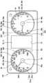
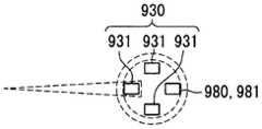
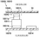
根据本公开的第一实施方式的车辆用显示装置100搭载在车辆上,并被设置在与作为视觉确认者的乘员就坐的座席对置的中控面板。如图1所示,车辆用显示装置100构成将通过指针40a、40b指示指标22a、22b进行的模拟显示、和通过图像显示器10显示的图像进行的数字显示组合而成的组合仪表,朝向视觉确认侧显示信息。由此,相对于车辆用显示装置100位于视觉确认侧的乘员能够意识到所显示的信息。作为被显示的信息,例如列举车辆的速度、发动机转速、燃料余量、发动机冷却水的水温、电动马达的电流值、其它车辆的异常等车辆的状态。作为其它被显示的信息,例如列举警报、道路信息、视野辅助信息、电子邮件等各种信息。Thevehicle display device 100 according to the first embodiment of the present disclosure is mounted on a vehicle, and is provided on a center control panel facing a seat on which an occupant, who is a visual observer, sits. As shown in FIG. 1 , thevehicle display device 100 constitutes an instrument cluster that combines the analog display by thepointers 40a and 40b indicating theindicators 22a and 22b and the digital display by the image displayed on theimage display 10 . side display information. Thereby, the occupant on the visual confirmation side with respect to thevehicle display device 100 can recognize the displayed information. The displayed information includes, for example, the speed of the vehicle, the engine speed, the remaining fuel level, the water temperature of the engine cooling water, the current value of the electric motor, and the state of the vehicle such as abnormality of other vehicles. As other displayed information, various information such as warning, road information, visual aid information, and e-mail are listed, for example.

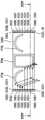
另外,车辆用显示装置100也如图2、3所示,成为与后面详述的拍摄系统4一体地形成的一体型的装置。In addition, as shown in FIGS. 2 and 3 , thevehicle display device 100 is also an integrated device formed integrally with theimaging system 4 described in detail later.

这样的车辆用显示装置100由图像显示器10、显示板20、可视光源部30、指针40a、40b、拍摄部60、图像处理部70以及近红外光照射部80等构成。Such avehicle display device 100 includes animage display 10 , adisplay panel 20 , a visiblelight source unit 30 ,pointers 40 a and 40 b , animaging unit 60 , an image processing unit 70 , a near-infraredlight irradiation unit 80 , and the like.

如图1所示,图像显示器10配置在装置100的大致中央。在本实施方式中,图像显示器10是使用了薄膜晶体管(Thin Film Transistor,TFT)的透射式的液晶面板,成为采用了由在二维方向上排列的多个液晶像素形成的有源矩阵型的液晶面板的液晶显示器。图像显示器10能够在矩形状的显示画面11上显示图像。此外,作为图像显示器10,也可以采用液晶显示器以外的有机EL显示器等。As shown in FIG. 1 , theimage display 10 is arranged substantially in the center of theapparatus 100 . In the present embodiment, theimage display 10 is a transmissive liquid crystal panel using a thin film transistor (TFT), and is of an active matrix type using a plurality of liquid crystal pixels arranged two-dimensionally. LCD panel LCD display. Theimage display 10 can display an image on arectangular display screen 11 . In addition, as theimage display 10, an organic EL display or the like other than a liquid crystal display can also be used.

显示板20一般被称为文字板,例如对由聚碳酸酯树脂树脂或丙烯酸树脂等合成树脂构成的透光性的基材的表面部分地或者整体实施半透光性或者遮光性的印刷,形成为平板状。此外,也可以代替印刷,而实施涂装,还可以通过粘贴等在显示板20上保持使近红外光透过的光学树脂或者光学滤光材料。Thedisplay panel 20 is generally referred to as a dial, and is formed by partially or entirely printing a surface of a translucent base material made of a polycarbonate resin resin or a synthetic resin such as an acrylic resin with semi-transparent or light-shielding properties. Flat. In addition, instead of printing, coating may be applied, and an optical resin or an optical filter material that transmits near-infrared light may be held on thedisplay panel 20 by sticking or the like.

如图1~3所示,显示板20配置在比图像显示器10更靠视觉确认侧。在显示板20中与图像显示器10重叠的位置上例如开有开口孔21,显示画面11的图像被显示于视觉确认侧,而不会干扰显示板20。在显示板20中,在夹着开口孔21的左右区域中分别形成有由指针40a、40b指示的指标22a、22b。通过可视光源部30从与视觉确认侧相反侧(以下,称为反视觉确认侧)照明显示板20的指标22a、22b。As shown in FIGS. 1 to 3 , thedisplay panel 20 is arranged on the visual confirmation side than theimage display 10 . In thedisplay panel 20 , for example, anopening 21 is formed at a position overlapping theimage display 10 , and the image of thedisplay screen 11 is displayed on the visual confirmation side without disturbing thedisplay panel 20 . In thedisplay panel 20 ,indicators 22 a and 22 b indicated by thepointers 40 a and 40 b are formed in the left and right regions sandwiching theopening hole 21 , respectively. Theindicators 22 a and 22 b of thedisplay panel 20 are illuminated by the visiblelight source unit 30 from the side opposite to the visual confirmation side (hereinafter, referred to as the opposite visual confirmation side).

可视光源部30配置在比显示板20更靠反视觉确认侧,具有发出可视显示光的多个显示用发光元件31。各显示用发光元件31例如采用发光二极管,各显示用发光元件31配置在比显示板20更靠反视觉确认侧,并安装在形成为平板状的基板9的视觉确认侧。各显示用发光元件31通过基板9上的导通图案与电源连接,从而朝向显示板20发出可视显示光。特别是在本实施方式中,作为各显示用发光元件31发出的可视显示光,采用由在400~800nm左右的波长的范围中广泛分布的光构成的白色光。The visiblelight source unit 30 is arranged on the anti-visual confirmation side than thedisplay panel 20 , and includes a plurality of display light-emitting elements 31 that emit visible display light. Each display light emitting element 31 is, for example, a light emitting diode, and each display light emitting element 31 is arranged on the opposite side of thedisplay panel 20 and is mounted on the side of thesubstrate 9 formed in a flat plate shape. Each display light-emitting element 31 is connected to a power source through a conduction pattern on thesubstrate 9 to emit visible display light toward thedisplay panel 20 . In particular, in the present embodiment, as the visible display light emitted by each display light-emitting element 31, white light composed of light widely distributed in a wavelength range of about 400 to 800 nm is used.

在显示板20上通过上述的印刷形成遮光区域SA以及显示区域DA。遮光区域SA占据显示板20的大多数的面积,例如通过遮光性的印刷形成暗色(例如黑色),从而对来自反视觉确认侧的可视显示光进行遮光。显示区域DA通过不实施半透光性的印刷或不实施印刷,而使来自反视觉确认侧的可视显示光透过到视觉确认侧,从乘员视觉确认发出可视显示光,并进行显示。因此,显示区域DA也称为透过区域。The light shielding area SA and the display area DA are formed on thedisplay panel 20 by the above-mentioned printing. The light-shielding area SA occupies most of the area of thedisplay panel 20, and is formed in a dark color (eg, black) by, for example, light-shielding printing, thereby shielding the visible display light from the anti-visual confirmation side. The display area DA transmits the visible display light from the anti-visual confirmation side to the visual confirmation side without performing semi-translucent printing or printing, and emits the visible display light from the occupant's visual confirmation and displays. Therefore, the display area DA is also called a transmission area.

如图1,2所示,分别与显示板20的左右区域对应地设置多个指针40a、40b。特别是在本实施方式中,指针40a、40b在左右区域中各设置一个。各指针40a、40b一体地具有连结部41以及指示部42。连结部41配置在比显示板20更靠反视觉确认侧,并与保持在平板状的基板9上的步进电机43的旋转轴连结。指示部42配置在比显示板20更靠视觉确认侧,呈针状。各指针40a、40b根据步进电机43的输出而绕指针轴AX转动,通过分别指示对应的指标22a、22b,从而显示与指示位置对应的信息。As shown in FIGS. 1 and 2 , a plurality ofpointers 40 a and 40 b are provided corresponding to the left and right regions of thedisplay panel 20 , respectively. In particular, in this embodiment, onepointer 40a, 40b is provided in each of the left and right regions. Each of thehands 40a and 40b has a connectingportion 41 and an indicatingportion 42 integrally. The connectingportion 41 is arranged on the opposite side of thedisplay panel 20 to be visually recognized, and is connected to the rotating shaft of the steppingmotor 43 held on theflat substrate 9 . Theindicator portion 42 is arranged on the visual confirmation side of thedisplay panel 20 and has a needle shape. Each of thepointers 40a and 40b rotates around the pointer axis AX according to the output of the steppingmotor 43, and by indicating the correspondingindexes 22a and 22b, respectively, information corresponding to the indicated position is displayed.

在本实施方式的显示板中,由左侧的区域的指针40a指示的指标22a成为表示车辆的速度的指标。指标22a包括相互成对的刻度指标23a以及文字指标24a。刻度指标23a通过将被遮光区域SA围起的显示区域DA的轮廓形成为以指针轴AX为中心的呈部分圆环状排列的刻度的形状而构成。文字指标24a与刻度指标23a对应,通过将被遮光区域SA围起的显示区域DA的轮廓形成为作为文字的数字的形状而构成。文字指标24a的数字以20km/h间距表示车辆的速度。而且,形成刻度指标23a以及文字指标24a的显示区域DA的整个区域成为通过印刷设置有白色的半透光性的白色滤光层25a,从而将来自可视光源部30的白色光作为大致保持原样的颜色的白色光发出到视觉确认侧的白色显示区域DAw。更详细而言,白色滤光层25a形成为从可视光使近红外光的各波长的光大致无遗漏地透过。In the display panel of the present embodiment, theindex 22a indicated by thepointer 40a in the area on the left is an index indicating the speed of the vehicle. Theindicators 22a includescale indicators 23a andcharacter indicators 24a which are paired with each other. Thescale index 23a is configured by forming the outline of the display area DA surrounded by the light-shielding area SA in the shape of a scale that is arranged in a partially annular shape with the pointer axis AX as the center. Thecharacter index 24a corresponds to thescale index 23a, and is configured by forming the outline of the display area DA surrounded by the light-shielding area SA in the shape of a numeral as a character. The numerals of thecharacter index 24a indicate the speed of the vehicle at intervals of 20 km/h. Furthermore, the entire area of the display area DA in which thescale indexes 23a and thecharacter indexes 24a are formed is provided with a white semi-transparentwhite filter layer 25a by printing, so that the white light from the visiblelight source unit 30 is kept substantially as it is. The white light of the color is emitted to the white display area DAw on the visual confirmation side. More specifically, thewhite filter layer 25a is formed so as to transmit the light of each wavelength of the near-infrared light almost completely from the visible light.

在本实施方式的显示板20中,由右侧的区域的指针40b指示的指标22b成为表示发动机转速的指标。指标22b包括相互成对的刻度指标23b以及文字指标24b。刻度指标23b通过将被遮光区域SA围起的显示区域DA的轮廓形成为以指针轴AX为中心的呈部分圆环状排列的刻度的形状而构成。文字指标24b与刻度指标23b对应,通过将被遮光区域SA围起的显示区域DA的轮廓形成为作为文字的数字的形状而构成。文字指标24b的数字以1000r/min间距表示发动机转速。而且,形成刻度指标23b的显示区域DA中表示发动机转速较大的值(例如5500r/min)的区域成为通过印刷设置有红系色的半透光性的红系色滤光层25b,从而将来自可视光源部30的白色光转换为红系色光,并发出到视觉确认侧的红系色显示区域DAr。更详细而言,红系色滤光层25b形成为,对可视光中比红系色光短的波长的光进行遮光,并从红系色光使近红外光的各波长的光大致无遗漏地透过。In thedisplay panel 20 of the present embodiment, theindex 22b indicated by thepointer 40b in the region on the right is an index indicating the engine speed. Theindex 22b includes ascale index 23b and acharacter index 24b which are paired with each other. Thescale index 23b is formed by forming the outline of the display area DA surrounded by the light-shielding area SA in the shape of scales arranged in a partial annular shape with the pointer axis AX as the center. Thecharacter index 24b corresponds to thescale index 23b, and is configured by forming the outline of the display area DA surrounded by the light-shielding area SA in the shape of a numeral as a character. The numerals of thecharacter index 24b represent the engine speed at intervals of 1000 r/min. In addition, in the display area DA where thescale index 23b is formed, an area indicating a large value (for example, 5500 r/min) of the engine speed becomes a red-coloredcolor filter layer 25b provided with a semi-transparent red color by printing, so that the redcolor filter layer 25b is provided by printing. The white light from the visiblelight source unit 30 is converted into red light, and emitted to the red display area DAr on the visual confirmation side. More specifically, the red-basedcolor filter layer 25b is formed so as to block light having a wavelength shorter than that of the red-based color light in the visible light, and to substantially eliminate the near-infrared light of each wavelength from the red-based color light. through.

此处,本实施方式中的红系色被定义为统称红色、橙色的颜色,红系色光被定义为统称红色光(620~750nm左右的波长的光)、橙色光(590~630nm左右的波长的光)、以及混合红色光和橙色光而被识别为红色光或橙色光的光的光。特别是本实施方式的红系色显示区域Dar发出红色光。Here, the red color in the present embodiment is defined as colors collectively referred to as red and orange, and the red color light is defined collectively as red light (light with a wavelength of about 620 to 750 nm) and orange light (with a wavelength of about 590 to 630 nm). light), and light that mixes red light and orange light to be identified as red light or orange light. In particular, the red color display region Dar of the present embodiment emits red light.

另外,形成刻度指标23b以及文字指标24b的显示区域DA中除了红系色显示区域Dar之外的区域成为与上述的白色显示区域同样的白色显示区域DAw。In addition, the area other than the red color display area Dar in the display area DA forming thescale index 23b and thecharacter index 24b becomes the white display area DAw similar to the above-described white display area.

这样,可视光源部30以及显示板20等构成通过可视显示光的发光显示信息的发光显示部2。In this way, the visiblelight source unit 30 , thedisplay panel 20 , and the like constitute the light-emittingdisplay unit 2 that displays information by emitting visible display light.

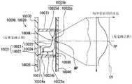
拍摄部60、图像处理部70以及近红外光照射部80配置在车辆用显示装置100的内部,构成对车辆内的拍摄对象进行拍摄的拍摄系统4。在本实施方式中,拍摄对象为车辆的乘员,特别是驾驶员的面部。拍摄系统4通过拍摄驾驶员的面部,并对该图像进行处理,从而利用于监视驾驶员的瞌睡、漫不经心的驾驶员状态监控(Driver Status Monitor,DSM)。Theimaging unit 60 , the image processing unit 70 , and the near-infraredlight irradiating unit 80 are arranged inside thevehicle display device 100 , and constitute animaging system 4 that captures an image of an imaging subject in the vehicle. In this embodiment, the photographing object is the occupant of the vehicle, especially the driver's face. The photographingsystem 4 is used for the Driver Status Monitor (DSM) to monitor the driver's drowsiness and inattentiveness by photographing the driver's face and processing the image.

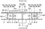
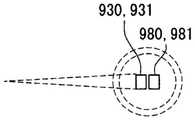
如图3所示,拍摄部60对被近红外光照射部80照明的拍摄对象进行拍摄。具体地,拍摄部60具有配置在比显示板20更靠反视觉确认侧的、例如图像显示器10的旁边等的相机61。在显示板20中与相机61对置的位置成为通过印刷设置有使包括可视光的上限的波长的光的近红外光透过的近红外光透过滤光层27的近红外光透过区域TAir。此处,可视光的上限的波长的光(以下,称为可视上限光)意味着接近780~830nm的人能够视觉确认的上限的波长的光。As shown in FIG. 3 , the photographingunit 60 photographs the photographic subject illuminated by the near-infraredlight irradiating unit 80 . Specifically, theimaging unit 60 includes a camera 61 that is arranged on the opposite side of thedisplay panel 20 for confirmation, for example, next to theimage display 10 or the like. The position facing the camera 61 in thedisplay panel 20 is a near-infrared light-transmitting region in which a near-infrared light-transmittingfilter layer 27 that transmits near-infrared light having a wavelength including the upper limit of visible light is provided by printing. TAir. Here, light with a wavelength of the upper limit of visible light (hereinafter, referred to as visible upper limit light) means light with a wavelength close to the upper limit that can be visually recognized by a person of 780 to 830 nm.

相机61具有检测元件62、以及用于在检测元件62上对拍摄对象进行成像的透镜63。作为检测元件62,例如采用CMOS传感器等从可视光到可视上限光(包括近红外光)具有良好的灵敏度,且检测的像的分辨率较高的元件。The camera 61 has a detection element 62 and a lens 63 for imaging a photographic subject on the detection element 62 . As the detection element 62 , for example, a CMOS sensor is used which has good sensitivity from visible light to upper limit of visible light (including near-infrared light) and has a high resolution of the detected image.

图像处理部70被实现为以将至少一个处理器、存储器、输入输出接口等安装在基板9上的电子电路为主体而构建的功能模块。处理器通过基于通过输入输出接口输入的来自检测元件62的信号来执行存储器中存储的计算机程序,从而能够实施图像处理。更详细而言,图像处理部70根据从检测元件62输入的信号来生成拍摄拍摄对象而获得的图像数据。生成的图像数据保持原样地被输出至车辆的ECU(Electric Control Unit:电子控制单元)等车辆用显示装置的外部,可以由该ECU进行解析,也可以由图像处理部70对图像数据进行解析,并判定驾驶员的瞌睡或漫不经心的有无。The image processing unit 70 is implemented as a functional module mainly composed of an electronic circuit in which at least one processor, a memory, an input/output interface, and the like are mounted on thesubstrate 9 . The processor can implement image processing by executing the computer program stored in the memory based on the signal from the detection element 62 input through the input-output interface. More specifically, the image processing unit 70 generates image data obtained by photographing the subject based on the signal input from the detection element 62 . The generated image data is output as it is to the outside of a vehicle display device such as an ECU (Electric Control Unit) of the vehicle, and the ECU may analyze the image data, or the image processing unit 70 may analyze the image data. And determine the driver's drowsiness or inattention.

如图2所示,近红外光照射部80将包括可视上限光的近红外光照射到视觉确认侧。本实施方式的近红外光照射部80具有多个近红外发光元件81,该近红外发光元件81以与可视光源部30的各显示用发光元件31相邻配置的方式被安装在基板9的视觉确认侧。各近红外发光元件81例如采用发光二极管。各近红外发光元件81通过基板9上的导通图案与电源连接,从而朝向显示板20发出包括可视上限光的近红外光。特别是在本实施方式中,例如采用在850nm具有峰值波长,半值宽度具有30~40nm左右的波长特性的近红外发光元件81。而且,各近红外发光元件81照射的光量的总和被设定为小于各显示用发光元件31照射的光量的总和。As shown in FIG. 2 , the near-infraredlight irradiating unit 80 irradiates the near-infrared light including the visible upper limit light to the visual confirmation side. The near-infraredlight irradiation unit 80 of the present embodiment includes a plurality of near-infrared light-emitting elements 81 mounted on thesubstrate 9 so as to be adjacent to the respective display light-emitting elements 31 of the visiblelight source unit 30 . Visual confirmation side. Each of the near-infrared light-emitting elements 81 is, for example, a light-emitting diode. Each of the near-infrared light-emitting elements 81 is connected to a power source through a conduction pattern on thesubstrate 9 , so as to emit near-infrared light including a visible upper limit light toward thedisplay panel 20 . In particular, in this embodiment, the near-infrared light-emitting element 81 having a peak wavelength at 850 nm and wavelength characteristics at half-value width of about 30 to 40 nm is used, for example. Furthermore, the total amount of light irradiated by each of the near-infrared light-emitting elements 81 is set to be smaller than the sum of the amount of light irradiated by each of the light-emitting elements 31 for display.

通过将显示用发光元件31和近红外发光元件81相互相邻地配置在共用的空间,可视显示光和包括可视上限光的近红外光两方都从反视觉确认侧入射到显示板20的各显示区域DA。By arranging the light-emitting element 31 for display and the near-infrared light-emitting element 81 adjacent to each other in a common space, both the visible display light and the near-infrared light including the visible upper limit light are incident on thedisplay panel 20 from the anti-visual confirmation side. of each display area DA.

因此,在各白色显示区域DAw中,如图4所示,在混合了包括可视上限光的近红外光的状态下,发出作为可视显示光的白色光。从各白色显示区域DAw发出的光中,可视上限光的比例被调整为充分低于作为可视显示光的白色光的比例。因此,即使将包括可视上限光的近红外光和作为可视显示光的白色光混合,乘员也较难看到浅红色,会被识别为白色。Therefore, in each white display area DAw, as shown in FIG. 4 , white light as visible display light is emitted in a state where near-infrared light including visible upper limit light is mixed. Among the lights emitted from the respective white display areas DAw, the ratio of the visible upper limit light is adjusted to be sufficiently lower than the ratio of the white light as the visible display light. Therefore, even if the near-infrared light including the visible upper limit light and the white light as the visible display light are mixed, the occupant is less likely to see the light red and is recognized as white.

另外,在各红系色显示区域Dar中,在混合了包括可视上限光的近红外光的状态下,发出作为可视显示光的红系色光。可视上限光、和作为可视显示光的红系色光由于色调相互接近,所以即使混合,乘员也几乎不会将可视上限光识别为单独的光。In addition, in each red-based color display area Dar, in a state where near-infrared light including visible upper limit light is mixed, red-based color light as visible display light is emitted. Since the visible upper limit light and the red color light, which is the visible display light, have close hues to each other, even if they are mixed, the occupant hardly recognizes the visible upper limit light as separate light.

而且,由于这样的白色显示区域DAw以及红系色显示区域Dar形成由指针40a、40b指示的指标22a、22b,所以在驾驶员视觉确认指标22a、22b时,该驾驶员的面部被自然地照明。与此同时,由于驾驶员不能够将可视上限光识别为单独的光,所以有可能很难认识到自己的面部因为拍摄而被照明。Furthermore, since the white display area DAw and the red-colored display area Dar form theindicators 22a and 22b indicated by thepointers 40a and 40b, when the driver visually confirms theindicators 22a and 22b, the driver's face is naturally illuminated . At the same time, since the driver cannot recognize the upper limit of visible light as a separate light, it may be difficult to recognize that his face is illuminated by shooting.

这样,近红外光照射部80照射的光中有可能被视觉确认的可视上限光被伪装(掩饰),以便限制被识别为单独存在的光。即,在本实施方式中,在共用的空间中使显示用发光元件31与近红外发光元件81相邻的可视光源部30、和设置有白色显示区域DAw以及红系色显示区域Dar的显示板20作为对照射到视觉确认侧的可视上限光进行伪装的伪装部3发挥作用。In this way, the visible upper limit light that may be visually recognized among the light irradiated by the near-infraredlight irradiating section 80 is camouflaged (masked) so as to limit the light recognized as being alone. That is, in the present embodiment, the visiblelight source unit 30 in which the display light-emitting element 31 and the near-infrared light-emitting element 81 are adjacent to each other, and the display provided with the white display area DAw and the red color display area Dar are displayed in a common space. Theplate 20 functions as acamouflage portion 3 that camouflages the upper limit visible light irradiated on the visual confirmation side.

(作用效果)(Effect)

以下重新对以上说明的第一实施方式的作用效果进行说明。Hereinafter, the effects of the first embodiment described above will be described again.

根据第一实施方式的车辆用显示装置,可视上限光被伪装部3伪装。这样的话,即使包括可视上限光的近红外光被近红外光照射部80照射到视觉确认侧,通过伪装,乘员较难单独识别可视上限光。其结果是能够抑制车辆的乘员视觉确认所显示的信息时的复杂的印象。According to the vehicle display device of the first embodiment, the visible upper limit light is disguised by the disguisingportion 3 . In this way, even if near-infrared light including the visible upper limit light is irradiated to the visual confirmation side by the near-infraredlight irradiating portion 80 , it is difficult for the occupant to recognize the visible upper limit light alone by camouflage. As a result, it is possible to suppress a complicated impression when the occupant of the vehicle visually recognizes the displayed information.

另外,根据第一实施方式,伪装部3通过在可视上限光中混合与可视上限光的波长不同的波长的可视光来对可视光的上限的波长的光进行伪装。通过这样的混色,由于可视上限光的颜色不会显眼为单独的颜色,所以乘员较难单独识别可视上限光的存在。因此,能够可靠地抑制复杂的印象。Further, according to the first embodiment, the disguisingunit 3 disguises light having a wavelength of the upper limit of visible light by mixing visible light of a wavelength different from the wavelength of the upper limit of visible light with the upper limit of visible light. With such color mixing, since the color of the upper limit of visible light is not conspicuous as a single color, it is difficult for the occupant to recognize the presence of the upper limit of visible light alone. Therefore, complicated impression can be suppressed reliably.

另外,根据第一实施方式,发光显示部2在混合了近红外光照射部80照射的包括可视上限光的近红外光的状态下发出可视显示光。即,可视上限光通过与发光显示部2发出的可视显示光混合而被伪装,所以即使乘员视觉确认通过发光显示部2显示的信息,也较难单独识别可视上限光的存在。因此,能够可靠地抑制复杂的印象。In addition, according to the first embodiment, the light-emittingdisplay unit 2 emits visible display light in a state where the near-infrared light including the visible upper limit light irradiated by the near-infraredlight irradiation unit 80 is mixed. That is, the visible upper limit light is camouflaged by being mixed with the visible display light emitted by the light emittingdisplay unit 2, so even if the occupant visually recognizes the information displayed by the light emittingdisplay unit 2, it is difficult to recognize the presence of the visible upper limit light alone. Therefore, complicated impression can be suppressed reliably.

另外,根据第一实施方式,发光显示部2具有发出作为可视显示光的红系色光的红系色显示区域DAr,从红系色显示区域Dar在混合了近红外光照射部80照射的包括可视上限光的近红外光的状态下发出红系色光。即,可视上限光通过与红系色显示区域DAr发出的红系色光混合而被伪装。由于可视上限光的色调与红系色光接近,所以极难单独识别可视上限光的存在。因此,复杂的印象的抑制效果显著。In addition, according to the first embodiment, the light-emittingdisplay unit 2 includes the red-based color display area DAr that emits red-based color light as visible display light, and the red-based color display area Dar is mixed with the near-infraredlight irradiating unit 80 to irradiate the area including It emits red color light in the state of near-infrared light of visible upper limit light. That is, the upper limit of visible light is camouflaged by mixing with the red light emitted from the red display area DAr. Since the hue of the visible upper limit light is close to that of the red color light, it is extremely difficult to identify the existence of the visible upper limit light alone. Therefore, the suppressing effect of complex impression is remarkable.

另外,根据第一实施方式,从白色显示区域DAw在混合了近红外光照射部80照射的包括可视上限光的近红外光的状态下,发出比可视上限光多的光量的白色光。即,可视上限光通过与白色显示区域DAw发出的白色光混合而被伪装。此时,由于白色光的光量多于可视上限光,所以即使混合作为可视显示光的白色光,乘员也较难看到为浅红色,会被识别为白色。因而,即使乘员视觉确认通过发光显示部2显示的信息,也较难单独识别可视上限光的存在。因此,能够可靠地抑制复杂的印象。In addition, according to the first embodiment, white light having an amount greater than the visible upper limit light is emitted from the white display area DAw in a state where the near-infrared light including the visible upper limit light irradiated by the near-infraredlight irradiating unit 80 is mixed. That is, the upper limit visible light is camouflaged by being mixed with the white light emitted from the white display area DAw. At this time, since the light amount of the white light is larger than the upper limit of visibility light, even if the white light, which is the visible display light, is mixed, the occupant is less likely to see it as light red, and is recognized as white. Therefore, even if the occupant visually recognizes the information displayed by the light-emittingdisplay unit 2, it is difficult to recognize the presence of the visible upper limit light alone. Therefore, complicated impression can be suppressed reliably.

另外,根据第一实施方式,通过在可视光源部30配置近红外光照射部80,从而发光显示部2使显示板20的显示区域DA中近红外光照射部80发出的包括可视上限光的近红外光透过到视觉确认侧。这样的话,由于在从透过区域发出的可视显示光中可靠地混合可视上限光,所以即使乘员视觉确认通过发光显示部2显示的信息,也极难单独识别可视上限光的存在,能够将可视上限光可靠地照射到视觉确认侧。In addition, according to the first embodiment, by arranging the near-infraredlight irradiating portion 80 in the visiblelight source portion 30 , the light-emittingdisplay portion 2 makes the light including the visible upper limit emitted by the near-infraredlight irradiating portion 80 in the display area DA of thedisplay panel 20 . The near-infrared light is transmitted to the visual confirmation side. In this way, since the visible upper limit light is reliably mixed with the visible display light emitted from the transmission area, even if the occupant visually recognizes the information displayed by the light-emittingdisplay unit 2, it is extremely difficult to recognize the presence of the visible upper limit light alone. The visible upper limit light can be reliably irradiated to the visual confirmation side.

另外,根据第一实施方式,还具备对被近红外光照射部80照明的拍摄对象进行拍摄的拍摄部60。由于拍摄部60能够感知并拍摄通过伪装而复杂的印象少、且照亮拍摄对象的可视上限光,所以可以兼得车辆用显示装置100的复杂的印象的抑制、和拍摄质量的降低抑制。In addition, according to the first embodiment, theimaging unit 60 for imaging the subject illuminated by the near-infraredlight irradiating unit 80 is further provided. Since theimaging unit 60 can perceive and capture less complex impressions due to camouflage and the visible upper limit light illuminating the subject, thevehicle display device 100 can achieve both suppression of complex impressions and reduction in image quality.

另外,根据第一实施方式的拍摄系统4,可视光的上限的光被伪装部3伪装。这样的话,即使包括可视光的上限的波长的光的近红外光被近红外光照射部80照射到视觉确认侧,通过伪装,乘员较难单独识别可视光的上限的波长的光。其结果是能够抑制车辆的乘员视觉确认所显示的信息时的复杂的印象。In addition, according to theimaging system 4 of the first embodiment, the light of the upper limit of visible light is disguised by the disguisingunit 3 . In this way, even if the near-infrared light including the light of the upper limit wavelength of visible light is irradiated to the visual confirmation side by the near-infraredlight irradiating part 80 , it is difficult for the occupant to recognize the light of the upper limit of visible light wavelength alone by camouflage. As a result, it is possible to suppress a complicated impression when the occupant of the vehicle visually recognizes the displayed information.

而且,由于拍摄部60能够感知并拍摄通过伪装而复杂的印象少、照亮拍摄对象的可视上限光,所以可以抑制拍摄质量的降低。Furthermore, since the photographingunit 60 can perceive and photograph the visible upper limit light that illuminates the photographic subject with few impressions complicated by camouflage, it is possible to suppress deterioration of photographing quality.

(第二实施方式)(Second Embodiment)

如图5~9所示,第二实施方式是第一实施方式的变形例。以与第一实施方式不同的点为中心对第二实施方式进行说明。As shown in FIGS. 5 to 9 , the second embodiment is a modification of the first embodiment. The second embodiment will be described focusing on the points different from the first embodiment.

第二实施方式的车辆用显示装置200能够显示车辆中的燃料效率的高低。具体地,如图5所示,在显示板220中,通过将被遮光区域SA围起的显示区域DA的轮廓形成为“ECO”的文字的形状,从而设置构成的环保显示灯226。Thevehicle display device 200 according to the second embodiment can display the level of fuel efficiency in the vehicle. Specifically, as shown in FIG. 5 , in thedisplay panel 220 , the outline of the display area DA surrounded by the light-shielding area SA is formed in the shape of the letter "ECO", thereby providing the constituted eco-display lamp 226 .

如图6所示,在比显示板220的环保显示灯226更靠反视觉确认侧配置有环保可视光源部230a,环保可视光源部230a具有发出可视显示光的显示用发光元件231a。与第一实施方式的可视光源部30同样地,显示用发光元件231a例如采用发光二极管。但是,该显示用发光元件231a发出在560nm左右具有峰值波长的绿色或黄绿色或被视觉确认为绿色的黄绿色波长光,作为可视显示光。As shown in FIG. 6 , the eco-visiblelight source portion 230a is disposed on the opposite side to the visual confirmation side than the eco-indicating lamp 226 of thedisplay panel 220, and the eco-visiblelight source portion 230a has a display light-emittingelement 231a that emits visible indication light. Like the visiblelight source unit 30 of the first embodiment, the light-emittingelement 231a for display is, for example, a light-emitting diode. However, the light-emittingelement 231a for display emits green or yellow-green wavelength light having a peak wavelength around 560 nm, or yellow-green wavelength light visually recognized as green as visible display light.

而且,形成环保显示灯226的显示区域DA的整个区域成为通过设置利用烟雾印刷而形成的半透光性的烟雾层226a,从而作为来自环保可视光源部230a的黄绿色波长光的大致保持原样的颜色的黄绿色波长光发出到视觉确认侧的黄绿色显示区域DAg。在燃料效率为规定值以上的情况下,该环保显示灯226通过点亮环保可视光源部230a的显示用发光元件231a而进行显示,在燃料效率小于规定值的情况下,通过熄灭显示用发光元件231a来停止显示。Furthermore, the entire area of the display area DA forming the eco-display lamp 226 is provided with asemi-translucent mist layer 226a formed by mist printing, so that the light of the yellow-green wavelength from the eco-visiblelight source portion 230a remains substantially as it is. The yellow-green wavelength light of the color is emitted to the yellow-green display area DAg on the visual confirmation side. When the fuel efficiency is greater than or equal to a predetermined value, the eco-display lamp 226 displays by turning on the display light-emittingelement 231a of the eco-visiblelight source portion 230a, and when the fuel efficiency is less than the predetermined value, it turns off the display light-emittingelement 231a.element 231a to stop the display.

另外,如图5所示,在第二实施方式中,以包围指针40a、40b的转动范围的方式设置有形成为从显示板220突出的圆环状的发光环250。如图7所示,在比发光环250更靠反视觉确认侧配置有环用可视光源部230b,环用可视光源部230b具有发出可视显示光的多个显示用发光元件231b。与环保可视光源部230a同样地,各显示用发光元件231b例如采用发光二极管。但是,该各显示用发光元件231b采用能够进行颜色的切换的多彩色的发光元件(所谓3in1类型的发光元件)。In addition, as shown in FIG. 5 , in the second embodiment, a light-emitting ring 250 formed in an annular shape protruding from thedisplay panel 220 is provided so as to surround the rotation range of thepointers 40 a and 40 b. As shown in FIG. 7 , a ring-use visiblelight source unit 230b is disposed on the anti-visual confirmation side rather than the light-emitting ring 250, and the ring-use visiblelight source unit 230b includes a plurality of display light-emittingelements 231b that emit visible display light. As with the eco-friendly visiblelight source unit 230a, each display light-emittingelement 231b is, for example, a light-emitting diode. However, as each display light-emittingelement 231b, a multi-color light-emitting element (so-called 3in1 type light-emitting element) capable of color switching is used.

来自各显示用发光元件231b的可视显示光被导光部件251导光后,透过显示板220的非印刷区域,无遗漏地入射到发光环250的整周。而且,这样的发光环250构成将可视显示光发出到视觉确认侧的显示区域DA。The visible display light from each display light-emittingelement 231 b is guided by thelight guide member 251 , passes through the non-printing area of thedisplay panel 220 , and is incident on the entire circumference of the light-emitting ring 250 without exception. Further, such a light-emitting ring 250 constitutes a display area DA that emits visible display light to the visual confirmation side.

发光环250根据环用可视光源部230b的发光色切换颜色。例如燃料效率在规定值以上的情况下,发光环250切换为发出黄绿色波长光作为可视显示光的黄绿色显示区域DAg。另外,例如在燃料效率小于规定值的情况下,发光环250切换为发出红系色光作为可视显示光的红系色显示区域DAr。另外,发光环250可以根据状况切换为发出白色光的白色显示区域DAw、发出蓝色光的蓝色显示区域等。The light-emitting ring 250 switches colors according to the emission color of the ring-use visiblelight source portion 230b. For example, when the fuel efficiency is greater than or equal to a predetermined value, the light-emitting ring 250 is switched to the yellow-green display area DAg that emits light of a yellow-green wavelength as visible display light. In addition, for example, when the fuel efficiency is less than a predetermined value, the light-emitting ring 250 is switched to the red-colored display area DAr that emits red-colored light as visible display light. In addition, the light-emitting ring 250 can be switched to a white display area DAw that emits white light, a blue display area that emits blue light, and the like according to the situation.

这样,环保可视光源部230a、环用可视光源部230b、显示板220以及发光环250等构成通过可视显示光的发光显示信息的发光显示部202。In this way, the eco-friendly visiblelight source portion 230a, the ring visiblelight source portion 230b, thedisplay panel 220, the light-emitting ring 250, and the like constitute the light-emitting display portion 202 that displays information by light-emitting visible display light.

第二实施方式的近红外光照射部280具有与环保可视光源部230a的显示用发光元件231a相邻配置的近红外发光元件281a、以及与环用可视光源部230b的显示用发光元件231b相邻配置的近红外发光元件281b。The near-infrared light irradiating unit 280 of the second embodiment includes a near-infrared light-emitting element 281a arranged adjacent to the display light-emittingelement 231a of the eco-friendly visiblelight source unit 230a, and a display light-emittingelement 231b adjacent to the ring-use visiblelight source unit 230b Near-infrared light-emitting elements 281b arranged adjacent to each other.

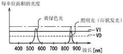
因此,在形成环保显示灯226的黄绿色显示区域Dag中,在环保显示灯226处于显示状态的期间中,如图8所示,在混合了包括可视上限光的近红外光的状态下,发出作为可视显示光的黄绿色波长光。由于包括可视上限光的近红外光的相对可见度至少为0.2以下,而作为可视显示光的黄绿色波长光的相对可见度是大致接近1的值(参照图9),所以即使混合,乘员也几乎不会将可视上限光识别为单独的光。Therefore, in the yellow-green display area Dag forming the eco-indicator light 226, while the eco-indicator light 226 is in the display state, as shown in FIG. It emits yellow-green wavelength light as visible display light. Since the relative visibility of near-infrared light including visible upper limit light is at least 0.2 or less, and the relative visibility of yellow-green wavelength light, which is visible display light, is a value close to 1 (see FIG. 9 ), even if mixed, the occupants will Visible ceiling light is hardly recognized as a separate light.

另外,在发光环250切换为黄绿色显示区域Dag的情况下,在混合了包括可视上限光的近红外光的状态下,发出作为可视显示光的黄绿色波长光。在这样的发光环250中,与环保显示灯226等同样地,乘员也几乎不会将可视上限光识别为单独的光。In addition, when the light-emitting ring 250 is switched to the yellow-green display area Dag, yellow-green wavelength light as visible display light is emitted in a state where near-infrared light including the upper limit of visible light is mixed. Even in such a light-emitting ring 250 , as with the eco-display light 226 and the like, the occupant hardly recognizes the upper limit visible light as a single light.

在发光环250切换为红系色显示区域DAr的情况下,在混合了包括可视上限光的近红外光的状态下,发出作为可视显示光的红系色光。在这样的发光环250中,与第一实施方式的红系色显示区域DAr同样地,乘员也几乎不会将可视上限光识别为单独的光。When the light-emitting ring 250 is switched to the red-based color display area DAr, the red-based color light as the visible display light is emitted in a state where near-infrared light including the visible upper limit light is mixed. In such a light-emitting ring 250, as in the red-colored display area DAr of the first embodiment, the occupant hardly recognizes the visible upper limit light as a single light.

这样,近红外光照射部280照射的光中有可能被视觉确认的可视上限光被伪装成限制被识别为单独存在的光。即,在第二实施方式中,在共用的空间中使显示用发光元件231a、231b与近红外发光元件281a、281b相邻的环保可视光源部230a以及环用可视光源部230b、设置有黄绿色显示区域Dag的显示板220、和以能够切换的方式设置各色的显示区域DA的发光环250作为对可视上限光进行伪装的伪装部203发挥作用。In this way, the visible upper limit light that can be visually recognized among the lights irradiated by the near-infrared light irradiating unit 280 is disguised as limiting the light recognized as being alone. That is, in the second embodiment, the display light-emittingelements 231a and 231b and the near-infrared light-emitting elements 281a and 281b adjacent to the environment-friendly visiblelight source part 230a and the ring-use visiblelight source part 230b are provided in a common space. Thedisplay panel 220 of the yellow-green display area Dag and the light-emitting ring 250 of the display area DA of each color are switchably provided, and function as thecamouflage part 203 for camouflaging the upper limit of light.

根据以上说明的第二实施方式,发光显示部202具有发出作为可视显示光的黄绿色波长光的黄绿色显示区域DAg,并从黄绿色显示区域Dag在混合了近红外光照射部280照射的包括可视上限光的近红外光的状态下,发出黄绿色波长光。黄绿色波长光的相对可见度在可视光中也特别高,而可视光的上限的光的相对可见度极低。通过这样的相对可见度的显著的差,极难单独识别可视光的上限的光的存在。因此,复杂的印象的抑制效果是显著的。According to the second embodiment described above, the light-emitting display unit 202 includes the yellow-green display area DAg that emits light of a yellow-green wavelength as visible display light, and the mixed near-infrared light irradiating unit 280 irradiates the yellow-green display area Dag from the yellow-green display area Dag. In the state of near-infrared light including visible upper limit light, yellow-green wavelength light is emitted. The relative visibility of yellow-green wavelength light is also particularly high in visible light, and the relative visibility of light at the upper limit of visible light is extremely low. With such a significant difference in relative visibility, it is extremely difficult to identify the presence of light at the upper limit of visible light alone. Therefore, the suppressing effect of complex impressions is remarkable.

(第三实施方式)(third embodiment)

如图10、11所示,第三实施方式是第一实施方式的变形例。以与第一实施方式不同的点为中心对第三实施方式进行说明。As shown in FIGS. 10 and 11 , the third embodiment is a modification of the first embodiment. The third embodiment will be described focusing on the points different from the first embodiment.

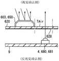
第三实施方式的近红外光照射部380与第一实施方式不同,未配置在可视光源部30。第三实施方式的近红外光照射部380具有近红外发光元件381,该近红外发光元件381配置在比显示板320更靠反视觉确认侧,且与配置有可视光源部30的空间隔开遮光壁8划分出的不同的空间中。Unlike the first embodiment, the near-infraredlight irradiation unit 380 of the third embodiment is not arranged in the visiblelight source unit 30 . The near-infraredlight irradiating portion 380 of the third embodiment includes a near-infrared light-emitting element 381 that is arranged on the opposite side of thedisplay panel 320 and is spaced apart from the space in which the visiblelight source portion 30 is arranged. in different spaces divided by the light-shieldingwall 8 .

显示板320在与形成白色显示区域DAw或者红系色显示区域Dar的指标22a、22b相邻的位置上形成有通过印刷设置有使包括可视上限光的近红外光透过的近红外光透过滤光层328的近红外光透过区域TAir。该近红外光透过区域TAir作为近红外光照射部380的一部分发挥作用。而且,在近红外光透过区域TAir中,从反视觉确认侧的近红外发光元件381入射到显示板320的包括可视上限光的近红外光透过到视觉确认侧。Thedisplay panel 320 is formed with a near-infrared light transmittance that transmits near-infrared light including the visible upper limit light by printing at a position adjacent to theindicators 22a and 22b forming the white display area DAw or the red-colored display area Dar. The near-infrared light of thefilter layer 328 transmits the region TAir. The near-infrared light transmission region TAir functions as a part of the near-infraredlight irradiation unit 380 . Further, in the near-infrared light transmission region TAir, the near-infrared light including the visible upper limit light incident on thedisplay panel 320 from the near-infrared light emitting element 381 on the anti-visual confirmation side is transmitted to the visual confirmation side.

近红外光照射部380的近红外光透过区域TAir与发光显示部302的白色显示区域DAw或者红系色显示区域DAr相邻配置,从而利用吸引性,使从近红外光照射部380照射可视上限光难以引人注目。The near-infrared light transmission region TAir of the near-infraredlight irradiating portion 380 is arranged adjacent to the white display region DAw or the red-colored display region DAr of the light-emittingdisplay portion 302, so that it is possible to irradiate from the near-infraredlight irradiating portion 380 by utilizing the attractiveness. Apparent ceiling light is hardly noticeable.

这样,近红外光照射部380照射的光中有可能被视觉确认的可视上限光被伪装成限制被识别为单独存在的光。即,在第三实施方式中,可视光源部30、和设置有白色显示区域DAw以及红系色显示区域Dar的显示板320作为对可视上限光进行伪装的伪装部303发挥作用。In this way, among the lights irradiated by the near-infraredlight irradiating section 380 , the upper limit of visible light, which may be visually recognized, is disguised as limiting the light recognized as being alone. That is, in the third embodiment, the visiblelight source unit 30 and thedisplay panel 320 provided with the white display area DAw and the red color display area Dar function as thecamouflage unit 303 for camouflaging the upper limit of visible light.

根据以上说明的第三实施方式,发光显示部302与近红外光照射部380相邻配置。即,可视上限光透过从相邻的位置发出的可视显示光而被伪装。与单独配置近红外光照射部380的情况相比,使可视上限光难以引人注目,所以乘员较难单独识别可视上限光。其结果是能够抑制车辆的乘员视觉确认所显示的信息时的复杂的印象。According to the third embodiment described above, the light-emittingdisplay portion 302 is arranged adjacent to the near-infraredlight irradiation portion 380 . That is, the visible upper limit light is disguised by the visible display light emitted from the adjacent position. Compared with the case where the near-infraredlight irradiating part 380 is separately arranged, the upper limit visible light is less noticeable, so it is difficult for the occupant to recognize the upper limit visible light alone. As a result, it is possible to suppress a complicated impression when the occupant of the vehicle visually recognizes the displayed information.

另外,根据第三实施方式,红系色显示区域Dar与近红外光照射部380相邻配置。即,可视上限光通过从相邻的位置发出的红系色光而被伪装。由于可视上限光的色调与红系色光接近,所以与单独配置近红外光照射部380的情况相比,可靠地难以引人注目,因而乘员较难单独识别可视上限光。其结果是能够抑制车辆的乘员视觉确认所显示的信息时的复杂的印象。In addition, according to the third embodiment, the red-based color display region Dar is arranged adjacent to the near-infraredlight irradiation portion 380 . That is, the upper limit of visible light is camouflaged by the red-colored light emitted from adjacent positions. Since the color tone of the upper limit of visible light is close to that of the red color light, compared with the case where the near-infraredlight irradiating part 380 is arranged alone, it is less likely to attract attention, and it is difficult for the occupant to recognize the upper limit of visible light alone. As a result, it is possible to suppress a complicated impression when the occupant of the vehicle visually recognizes the displayed information.

(第四实施方式)(Fourth Embodiment)

如图12~14所示,第四实施方式是第二实施方式的变形例。以与第二实施方式不同的点为中心对第四实施方式进行说明。As shown in FIGS. 12 to 14 , the fourth embodiment is a modification of the second embodiment. The fourth embodiment will be described focusing on the points different from the second embodiment.

第四实施方式的近红外光照射部480与第二实施方式不同,未配置在环保可视光源部230a以及环用可视光源部230b。第四实施方式的近红外光照射部480具有近红外发光元件481a,该近红外发光元件481a配置在比显示板420更靠反视觉确认侧,且与配置有环保可视光源部230a的空间隔开遮光壁8划分出的不同的空间中。Unlike the second embodiment, the near-infraredlight irradiation unit 480 of the fourth embodiment is not arranged in the eco-friendly visiblelight source unit 230 a and the ring visiblelight source unit 230 b. The near-infraredlight irradiating portion 480 of the fourth embodiment includes a near-infrared light-emitting element 481a that is arranged on the opposite side of thedisplay panel 420 and is spaced apart from the space in which the eco-friendly visiblelight source portion 230a is arranged. In different spaces divided by theshading wall 8.

显示板420在与形成黄绿色显示区域Dag的环保显示灯226相邻的位置上形成有通过印刷设置有使包括可视上限光的近红外光透过的近红外光透过滤光层428的近红外光透过区域TAir。该近红外光透过区域TAir作为近红外光照射部480的一部分发挥作用。而且,在近红外光透过区域TAir中,从反视觉确认侧的近红外发光元件481a入射到显示板420的包括可视上限光的近红外光透过到视觉确认侧。Thedisplay panel 420 is formed with a near-infrared light-transmittingfilter layer 428 that transmits the near-infrared light including the visible upper limit light by printing at a position adjacent to the eco-friendly display lamp 226 forming the yellow-green display area Dag. Infrared light is transmitted through the area TAir. This near-infrared light transmission region TAir functions as a part of the near-infraredlight irradiation unit 480 . Further, in the near-infrared light transmission region TAir, near-infrared light including the visible upper limit light incident on thedisplay panel 420 from the near-infrared light emitting element 481a on the anti-visual confirmation side is transmitted to the visual confirmation side.

这样,通过近红外光照射部480的近红外光透过区域TAir与形成有发光显示部402的黄绿色显示区域Dag的环保显示灯226相邻配置,从而在环保显示灯226处于显示状态的期间,使从近红外光照射部480照射可视上限光难以引人注目。In this way, the near-infrared light transmission region TAir of the near-infraredlight irradiating portion 480 is arranged adjacent to the eco-display lamp 226 in which the yellow-green display region Dag of the light-emitting display portion 402 is formed, so that the eco-indicator lamp 226 is in the display state during the period when the light-emitting display portion 402 is formed. , making it difficult to draw attention to the upper visible light from the near-infraredlight irradiating part 480 .

另外,第四实施方式的近红外光照射部480具有近红外发光元件481b,该近红外发光元件481b配置在比显示板420更靠反视觉确认侧、且与配置有环用可视光源部230b的空间隔开遮光壁8划分出的不同的空间中。In addition, the near-infraredlight irradiating part 480 of the fourth embodiment has a near-infrared light-emitting element 481b which is arranged on the opposite side of thedisplay panel 420 and on the side where the ring visiblelight source part 230b is arranged. The space is separated into different spaces divided by the light-shieldingwall 8 .

显示板420在与以能够进行颜色的切换的方式形成黄绿色显示区域DAg以及红系色显示区域DAr等的发光环250相邻的位置形成有通过印刷设置有使包括可视上限光的近红外光透过的近红外光透过滤光层428的近红外光透过区域TAir。该近红外光透过区域TAir作为近红外光照射部480的一部分发挥作用。而且,在近红外光透过区域TAir中,从反视觉确认侧的近红外发光元件481b入射到显示板420的包括可视上限光的近红外光透过到视觉确认侧。In thedisplay panel 420, a near-infrared light including a visible upper limit light is formed by printing at a position adjacent to the light-emitting ring 250 in which the yellow-green display area DAg, the red-colored display area DAr, and the like are formed so as to be able to switch colors. The near-infrared light-transmitting region TAir of the light-transmittingfilter layer 428 is near-infrared light-transmitting. This near-infrared light transmission region TAir functions as a part of the near-infraredlight irradiation unit 480 . Further, in the near-infrared light transmission region TAir, the near-infrared light including the visible upper limit light incident on thedisplay panel 420 from the near-infrared light emitting element 481b on the anti-visual confirmation side is transmitted to the visual confirmation side.

这样,通过将近红外光照射部480的近红外光透过区域TAir与以能够进行颜色的切换的方式形成发光显示部402的黄绿色显示区域DAg以及红系色显示区域DAr等的发光环250相邻配置,从而利用吸引性,使从近红外光照射部480照射可视上限光难以引人注目。In this way, the near-infrared light transmission region TAir of the near-infraredlight irradiating portion 480 is in contact with the light-emitting ring 250 that forms the yellow-green display region DAg and the red-colored display region DAr of the light-emitting display portion 402 so as to be able to switch colors. By being arranged adjacent to each other, it is difficult to attract attention when the upper visible limit light is irradiated from the near-infraredlight irradiating part 480 by utilizing the attractiveness.

这样,近红外光照射部480照射的光中有可能被视觉确认的可视上限光被伪装成限制被识别为单独存在的光。即,在第四实施方式中,环保可视光源部230a以及环用可视光源部230b、设置有黄绿色显示区域Dag的显示板420、及以能够切换的方式设置有各色的显示区域DA的发光环250作为对可视上限光进行伪装的伪装部403发挥作用。In this way, among the lights irradiated by the near-infraredlight irradiating section 480 , the visible upper limit light, which may be visually recognized, is disguised as limiting the light recognized as being alone. That is, in the fourth embodiment, the eco-friendly visiblelight source unit 230a and the ring visiblelight source unit 230b, thedisplay panel 420 provided with the yellow-green display area Dag, and thedisplay panel 420 provided with the display areas DA of each color switchably The light-emitting ring 250 functions as acamouflage portion 403 for camouflaging the upper limit visible light.

根据以上说明的第四实施方式,黄绿色显示区域Dag与近红外光照射部480相邻配置。即,可视上限光通过从相邻的位置发出的黄绿色波长光而被伪装。黄绿色波长光的相对可见度在可视光中也特别高,可视光的上限的光的相对可见度极低。因此,与单独配置近红外光照射部480的情况下相比,使可视上限光可靠地难以引人注目,所以乘员较难单独识别可视上限光。其结果是能够抑制车辆的乘员视觉确认所显示的信息时的复杂的印象。According to the fourth embodiment described above, the yellow-green display region Dag is arranged adjacent to the near-infraredlight irradiation portion 480 . That is, the upper limit of visible light is camouflaged by yellow-green wavelength light emitted from adjacent positions. The relative visibility of yellow-green wavelength light is also particularly high in visible light, and the relative visibility of light at the upper limit of visible light is extremely low. Therefore, compared with the case where the near-infraredlight irradiating portion 480 is separately arranged, the upper limit visible light is reliably made less noticeable, and therefore it is difficult for the occupant to recognize the upper limit visible light alone. As a result, it is possible to suppress a complicated impression when the occupant of the vehicle visually recognizes the displayed information.

(第五实施方式)(Fifth Embodiment)

如图15所示,第五实施方式是第一实施方式的变形例。以与第一实施方式不同的点为中心对第五实施方式进行说明。As shown in FIG. 15 , the fifth embodiment is a modification of the first embodiment. The fifth embodiment will be described focusing on the points different from the first embodiment.

在第五实施方式中,以包围指针40a、40b的转动范围的方式设置有形成为从显示板520突出的圆环状的反射环550。反射环550例如通过在由聚碳酸酯树脂树脂或丙烯酸树脂等合成树脂构成的透光性的基材的视觉确认侧的表面镀覆或者蒸镀锡或银等的金属等来形成极薄的金属薄膜而成的。这样的反射环550将从视觉确认侧入射的外光再次反射到视觉确认侧,并且作为形成为能够使反视觉确认侧的光透过到视觉确认侧的单向镜或半透半反镜状的外光反射部发挥作用。In the fifth embodiment, areflection ring 550 formed in an annular shape protruding from the display panel 520 is provided so as to surround the rotational range of thepointers 40a and 40b. Thereflection ring 550 is formed of an extremely thin metal by, for example, plating or vapor-depositing a metal such as tin or silver on the surface of a translucent base material made of a polycarbonate resin resin or a synthetic resin such as an acrylic resin on the visual confirmation side. made of thin film. Such areflection ring 550 reflects the external light incident from the visual confirmation side to the visual confirmation side again, and is formed in the shape of a one-way mirror or a half mirror that can transmit the light from the opposite visual confirmation side to the visual confirmation side. The external light reflection part of the

作为外光,除了透过挡风玻璃入射到车室内的太阳光之外,还列举车内灯的照明光、从车辆导航的显示画面发出的显示光等。Examples of the external light include not only sunlight entering the vehicle interior through the windshield, but also illumination light from an interior lamp, display light emitted from a display screen for vehicle navigation, and the like.

近红外光照射部580配置有在比反射环550更靠反视觉确认侧配置的多个近红外发光元件581。来自近红外发光元件581的包括可视上限光的近红外光被导光部件551导光后,透过显示板520的非印刷区域,无遗漏地入射到反射环550的整周。The near-infrared light irradiating portion 580 is provided with a plurality of near-infrared light-emitting elements 581 arranged on the opposite visual confirmation side than thereflection ring 550 . The near-infrared light including the visible upper limit light from the near-infrared light-emitting element 581 is guided by thelight guide member 551 , passes through the non-printing area of the display panel 520 , and is incident on the entire circumference of thereflection ring 550 without exception.

而且,反射环550使近红外光照射部580照射的包括可视上限光的近红外光透过到视觉确认侧。由此,包括可视上限光的近红外光在混合了被反射环550反射的外光的状态下照射到视觉确认侧。因此,乘员较难将可视上限光识别为单独的光。Furthermore, thereflection ring 550 transmits the near-infrared light including the visible upper limit light irradiated by the near-infrared light irradiating section 580 to the visual confirmation side. Thereby, the near-infrared light including the visible upper limit light is irradiated to the visual confirmation side in a state of being mixed with the external light reflected by thereflection ring 550 . Therefore, it is difficult for the occupant to recognize the upper visible light as separate light.

这样,近红外光照射部580照射的光中有可能被视觉确认的可视上限光被伪装成限制被识别为单独存在的光。即,在第五实施方式中,反射环550作为对可视上限光进行伪装的伪装部503发挥作用。In this way, among the lights irradiated by the near-infrared light irradiating section 580 , the visible upper limit light, which may be visually recognized, is disguised as limiting the light recognized as being alone. That is, in the fifth embodiment, thereflection ring 550 functions as the camouflage portion 503 for camouflaging the upper limit visible light.

根据以上说明的第五实施方式,作为外光反射部的反射环550配置在比近红外光照射部580更靠视觉确认侧,使近红外光照射部580照射的包括可视上限光的近红外光透过,从而在混合了包括可视上限光的近红外光的状态下将外光反射到视觉确认侧。即,可视上限光通过透过反射环550而与被反射环550反射的外光混合以被伪装。因此,即使乘员与通过发光显示部2显示的信息一起视觉确认反射环550,也较难单独识别可视上限光的存在。因此,能够抑制复杂的印象。According to the fifth embodiment described above, thereflection ring 550 serving as the external light reflecting portion is disposed on the visual confirmation side rather than the near-infrared light irradiation portion 580 , and the near-infrared light including the visible upper limit light is irradiated by the near-infrared light irradiation portion 580 . The light is transmitted, thereby reflecting external light to the visual confirmation side in a state of being mixed with near-infrared light including visible upper limit light. That is, the visible upper limit light is camouflaged by passing through thereflection ring 550 and mixing with the external light reflected by thereflection ring 550 . Therefore, even if the occupant visually recognizes thereflection ring 550 together with the information displayed by the light-emittingdisplay unit 2, it is difficult to recognize the presence of the upper limit light visible alone. Therefore, a complicated impression can be suppressed.

(第六实施方式)(Sixth Embodiment)

如图16所示,第六实施方式是第一实施方式的变形例。以与第一实施方式不同的点为中心,对第六实施方式进行说明。As shown in FIG. 16 , the sixth embodiment is a modification of the first embodiment. The sixth embodiment will be described focusing on the points different from the first embodiment.

在第六实施方式中,以包围指针40a、40b的转动范围的方式设置有形成为从显示板620突出的圆环状的反射环650。反射环650例如通过在由合成树脂构成的基材的视觉确认侧的表面镀覆或者蒸镀铝等金属等来形成金属反射膜而成的。这样的反射环650与第五实施方式的反射环650不同,虽然没有形成为使来自反视觉确认侧的光透过到视觉确认侧,但作为将从视觉确认侧入射的外光再次反射到视觉确认侧的镜状的外光反射部发挥作用。In the sixth embodiment, thereflection ring 650 formed in an annular shape protruding from the display panel 620 is provided so as to surround the rotational range of thepointers 40a and 40b. Thereflection ring 650 is formed by, for example, forming a metal reflection film by plating or vapor deposition of a metal such as aluminum on the surface of the base material made of synthetic resin on the visual confirmation side. Such areflection ring 650 is different from thereflection ring 650 of the fifth embodiment in that it is not formed so as to transmit the light from the anti-visual confirmation side to the visual confirmation side, but is formed to reflect the external light incident from the visual confirmation side to the visual confirmation side again. The mirror-shaped external light reflecting portion on the confirmation side functions.

显示板620在与反射环650相邻的位置形成有通过印刷设置有使包括可视上限光的近红外光透过的近红外光透过滤光层628的近红外光透过区域TAir。近红外光照射部680具有配置在比近红外光透过区域TAir更靠反视觉确认侧的近红外发光元件681。The display panel 620 is formed with a near-infrared light transmitting region TAir in which a near-infrared light transmittingfilter layer 628 that transmits near-infrared light including the visible upper limit light is provided by printing at a position adjacent to thereflection ring 650 . The near-infrared light irradiation unit 680 has a near-infrared light emitting element 681 arranged on the side for anti-visual confirmation rather than the near-infrared light transmission region TAir.

在作为近红外光照射部680的一部分发挥作用的近红外光透过区域TAir中,从反视觉确认侧的近红外发光元件681入射到显示板620的包括可视上限光的近红外光透过到视觉确认侧。In the near-infrared light transmission region TAir that functions as a part of the near-infrared light irradiating portion 680 , near-infrared light including the visible upper limit light that is incident on the display panel 620 from the near-infrared light-emitting element 681 on the side of the anti-visual confirmation is transmitted therethrough to the visual confirmation side.

这样,通过将近红外光照射部680的近红外光透过区域TAir与将外光反射到视觉确认侧的反射环650相邻配置,从而可视上限光混进外光的晃眼,使从近红外光照射部680照射可视上限光难以引人注目。In this way, by arranging the near-infrared light transmitting region TAir of the near-infrared light irradiating part 680 adjacent to thereflection ring 650 that reflects the external light to the visual confirmation side, the upper limit of visible light is mixed with the glare of the external light, and the light from the near-infrared It is difficult for the light irradiating part 680 to irradiate the visible upper limit light.

这样,近红外光照射部680照射的光中有可能被视觉确认的可视上限光被伪装成限制被识别为单独存在的光。即,在第六实施方式中,反射环650作为对可视上限光进行伪装的伪装部603发挥作用。In this way, among the lights irradiated by the near-infrared light irradiating unit 680 , the upper limit of visible light, which may be visually recognized, is disguised as limiting the light recognized as being alone. That is, in the sixth embodiment, thereflection ring 650 functions as the camouflage portion 603 for camouflaging the upper limit visible light.

根据以上说明的第六实施方式,作为外光反射部的反射环650与近红外光照射部680相邻配置。即,可视上限光通过被相邻的位置反射的外光而被伪装。因此,与单独配置近红外光照射部680的情况下相比,可靠地使可视上限光难以引人注目,所以乘员较难单独识别可视上限光。其结果是能够抑制车辆的乘员视觉确认所显示的信息时的复杂的印象。According to the sixth embodiment described above, thereflection ring 650 serving as the external light reflection portion is arranged adjacent to the near-infrared light irradiation portion 680 . That is, the upper limit of visible light is disguised by the external light reflected by the adjacent position. Therefore, compared with the case where the near-infrared light irradiating portion 680 is separately arranged, the upper limit visible light is surely made less noticeable, and therefore it is difficult for the occupant to recognize the upper limit visible light alone. As a result, it is possible to suppress a complicated impression when the occupant of the vehicle visually recognizes the displayed information.

(第七实施方式)(Seventh Embodiment)

如图17所示,第七实施方式是第一实施方式的变形例。以与第一实施方式不同的点为中心对第七实施方式进行说明。As shown in FIG. 17 , the seventh embodiment is a modification of the first embodiment. The seventh embodiment will be described focusing on the points different from the first embodiment.

在第七实施方式中,以包围指针40a、40b的转动范围的方式设置有形成为从显示板720突出的圆环状的红系色环750。红系色环750例如在由合成树脂构成的基材的视觉确认侧的表面设置有利用红系色的遮光性印刷而形成的红系色层,并作为形成为对指针40a、40b以及发光显示部2对信息的显示进行加饰的红系色的红系色加饰部发挥作用。特别是本实施方式的红系色环形成为红色,但也可以形成为橙色。In the seventh embodiment, ared color ring 750 formed in an annular shape protruding from thedisplay panel 720 is provided so as to surround the rotational range of thepointers 40 a and 40 b. For example, the red-basedcolor ring 750 is provided with a red-based color layer formed by light-shielding printing of the red-based color on the surface of the base material made of synthetic resin on the visual confirmation side, and is formed as the counter-pointers 40a and 40b and the light-emitting display. Thepart 2 functions as a red-colored embellishment part for embellishing the display of information. In particular, the red color ring of the present embodiment is red, but it may be formed to be orange.

显示板720在与红系色环750相邻的位置形成有通过印刷设置有使包括可视上限光的近红外光透过的近红外光透过滤光层728的近红外光透过区域TAir。近红外光照射部780具有被配置在比近红外光透过区域TAir更靠反视觉确认侧的近红外发光元件781。Thedisplay panel 720 has a near-infrared light transmitting region TAir in which a near-infrared light transmittingfilter layer 728 that transmits near-infrared light including the visible upper limit light is provided by printing at a position adjacent to the red-basedcolor ring 750 . The near-infrared light irradiation unit 780 has a near-infrared light emitting element 781 arranged on the side that is opposite to the visual confirmation side than the near-infrared light transmission region TAir.

在作为近红外光照射部780的一部分发挥作用的近红外光透过区域TAir中,从反视觉确认侧的近红外发光元件781入射到显示板720的包括可视上限光的近红外光透过到视觉确认侧。In the near-infrared light transmission region TAir that functions as a part of the near-infrared light irradiating section 780 , near-infrared light including the visible upper limit light, which is incident on thedisplay panel 720 from the near-infrared light-emitting element 781 on the side of the anti-visual confirmation, is transmitted therethrough. to the visual confirmation side.

这样通过使近红外光照射部780的近红外光透过区域TAir与红系色环750相邻配置,可视上限光混进色调接近的红系色环,使从近红外光照射部780照射可视上限光难以引人注目。By arranging the near-infrared light transmitting region TAir of the near-infrared light irradiating part 780 to be adjacent to the red-basedcolor ring 750 in this way, the upper limit of visible light is mixed into the red-based color ring having a similar hue, and the near-infrared light irradiating part 780 is irradiated from the near-infrared light irradiating part 780 . Visible ceiling light is hardly noticeable.

这样,近红外光照射部780照射的光中有可能被视觉确认的可视上限光被伪装成限制被识别为单独存在的光。即,在第七实施方式中,红系色环750作为对可视上限光进行伪装的伪装部703发挥作用。In this way, among the lights irradiated by the near-infrared light irradiating unit 780 , the upper limit of visible light, which may be visually recognized, is disguised as limiting the light recognized as being alone. That is, in the seventh embodiment, the red-basedcolor ring 750 functions as the camouflage portion 703 that camouflages the upper limit visible light.

根据以上说明的第七实施方式,作为红系色加饰部的红系色环750与近红外光照射部780相邻配置。即,可视上限光通过在相邻的位置被视觉确认的红系色而被伪装。由于可视上限光与红系色色调接近,所以与单独配置近红外光照射部780的情况相比,可靠地难以引人注目,因而乘员较难单独识别可视上限光。其结果是能够抑制车辆的乘员视觉确认所显示的信息时的复杂的印象。According to the seventh embodiment described above, the red-basedcolor ring 750 serving as the red-based color decoration portion is arranged adjacent to the near-infrared light irradiation portion 780 . That is, the visible upper limit light is camouflaged by the red color that is visually recognized at an adjacent position. Since the visible upper limit light is close to the red color tone, compared with the case where the near-infrared light irradiating part 780 is arranged alone, it is less likely to attract attention, and it is difficult for the occupant to recognize the visible upper limit light alone. As a result, it is possible to suppress a complicated impression when the occupant of the vehicle visually recognizes the displayed information.

(第八实施方式)(Eighth Embodiment)

如图18所示,第八实施方式是第一实施方式的变形例。以与第一实施方式不同的点为中心对第八实施方式进行说明。As shown in FIG. 18 , the eighth embodiment is a modification of the first embodiment. The eighth embodiment will be described focusing on the points different from the first embodiment.

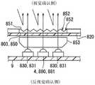
在第八实施方式的装置的外周部以封闭显示板820的方式设置有通过发出可视加饰光而对该装置对信息的显示进行加饰的发光加饰部802。具体地,发光加饰部802具有加饰用可视光源部830、被配置在比加饰用可视光源部830更靠视觉确认侧的凹凸透过构造体850。A light-emitting decoration portion 802 that decorates the display of information by the device by emitting visible decoration light is provided on the outer peripheral portion of the device of the eighth embodiment so as to close thedisplay panel 820 . Specifically, the light-emitting decoration portion 802 includes a visible light source portion 830 for decoration, and a concave-convex transmission structure 850 arranged on the visual confirmation side of the visible light source portion 830 for decoration.

加饰用可视光源部830具有发出可视加饰光的多个加饰用发光元件831。各加饰用发光元件831例如采用发光二极管,各加饰用发光元件831安装在基板9的视觉确认侧。各加饰用发光元件831通过基板9上的导通图案与电源连接,从而朝向凹凸透过构造体850发出可视显示光。特别是在本实施方式中,作为各加饰用发光元件831发出的可视加饰光,采用由在400~800nm左右的波长的范围中广泛分布的光构成的白色光。The visible light source portion 830 for decoration has a plurality of light-emitting elements 831 for decoration that emit visible decoration light. Each light-emitting element for decoration 831 is, for example, a light-emitting diode, and each light-emitting element 831 for decoration is mounted on the visual confirmation side of thesubstrate 9 . Each decorative light-emitting element 831 is connected to a power source through a conduction pattern on thesubstrate 9 , and emits visible display light toward the concave-convex transmission structure 850 . In particular, in the present embodiment, white light composed of light widely distributed in a wavelength range of about 400 to 800 nm is used as the visible decoration light emitted by each decoration light-emitting element 831 .

凹凸透过构造体850例如由聚碳酸酯树脂树脂或丙烯酸树脂等合成树脂形成,并形成为能够使近红外光以及可视光透过。凹凸透过构造体850在其视觉确认侧的表面形成有复杂的凹凸构造851,例如在本实施方式中,具有模仿金刚石切割的构造。通过这样的凹凸构造851,从加饰用可视光源部830经过导光部件853的可视加饰光被折射,并透过凹凸透过构造体850到视觉确认侧,所以给乘员提供伴随复杂的加饰花纹的照明。另外,通过将基于凹凸构造851的各折射面852形成为镜面状,从而凹凸透过构造体850也作为将从视觉确认侧入射的外光再次反射到视觉确认侧的外光反射部发挥作用。The uneven transmission structure 850 is formed of, for example, a synthetic resin such as polycarbonate resin resin or acrylic resin, and is formed so as to transmit near-infrared light and visible light. The concavo-convex transmissive structure 850 has a complex concavo-convex structure 851 formed on the surface on the side that is visually recognized, for example, in the present embodiment, it has a structure imitating a diamond cut. With the concavo-convex structure 851, the visible decorative light passing through thelight guide member 853 from the decorative visible light source portion 830 is refracted, and passes through the concavo-convex transmission structure 850 to the visual confirmation side, so that the occupant is provided with a complicated accompanying decorative patterned lighting. In addition, by forming each refractingsurface 852 based on the concavo-convex structure 851 into a mirror-like shape, the concavo-convex transmission structure 850 also functions as an external light reflecting portion that re-reflects the external light incident from the visual confirmation side to the visual confirmation side.

第八实施方式的近红外光照射部880在与加饰用可视光源部830共用的空间中具有与加饰用发光元件831相邻配置的多个近红外发光元件881。因此,在凹凸透过构造体850中,在混合了包括可视上限光的近红外光的状态下,发出作为可视加饰光的白色光。从凹凸透过构造体850发出的光中可视上限光的比例被调整为充分低于作为可视加饰光的白色光的比例。因此,即使包括可视加饰光的近红外光和作为可视加饰光的白色光混合,乘员也较难看到为浅红色,而会被识别为白色光。The near-infrared light irradiation part 880 of the eighth embodiment has a plurality of near-infrared light-emitting elements 881 arranged adjacent to the light-emitting element 831 for decoration in the space shared with the visible light source part 830 for decoration. Therefore, in the concavo-convex transmissive structure 850 , white light as visible decorative light is emitted in a state where near-infrared light including the upper limit of visible light is mixed. The ratio of the visible upper limit light in the light emitted from the uneven transmission structure 850 is adjusted to be sufficiently lower than the ratio of the white light as the visible decorative light. Therefore, even if the near-infrared light including the visible decorative light and the white light as the visible decorative light are mixed, the occupant is less likely to see it as light red, and is recognized as white light.

此外,通过由各折射面852中的折射引起的色差、进而与被反射的外光的混合,乘员将可视上限光识别为单独的光是极困难的。In addition, it is extremely difficult for the occupant to recognize the upper limit visible light as separate light due to the chromatic aberration caused by the refraction in eachrefraction surface 852 and the mixing with the reflected external light.

这样,近红外光照射部880照射的光中有可能被视觉确认的可视上限光被伪装成限制被识别为单独存在的光。即,在本实施方式中,发光加饰部802作为对可视上限光进行伪装的伪装部803发挥作用。In this way, the visible upper limit light that can be visually recognized among the lights irradiated by the near-infrared light irradiating section 880 is disguised as limiting the light recognized as being alone. That is, in the present embodiment, the light-emitting decoration portion 802 functions as the camouflage portion 803 that camouflages the upper limit visible light.

根据以上说明的第八实施方式,发光加饰部802在混合了近红外光照射部880照射的包括可视上限光的近红外光的状态下发出可视加饰光。即,由于可视上限光通过与发光加饰部802发出的可视加饰光混合而被伪装,即使乘员与通过发光显示部2显示的信息一起视觉确认发光加饰部802,也较难单独识别可视上限光的存在。因此,能够抑制复杂的印象。According to the eighth embodiment described above, the light-emitting decoration portion 802 emits the visible decoration light in a state where the near-infrared light including the visible upper limit light irradiated by the near-infrared light irradiation portion 880 is mixed. That is, since the visible upper limit light is camouflaged by being mixed with the visible decorative light emitted by the light-emitting decoration portion 802 , even if the occupant visually confirms the light-emitting decoration portion 802 together with the information displayed on the light-emittingdisplay portion 2 , it is difficult to separate the light-emitting decoration portion 802 . Identify the presence of upper visible light. Therefore, a complicated impression can be suppressed.

(第九实施方式)(Ninth Embodiment)

如图19、20所示,第九实施方式是第一实施方式的变形例。以与第一实施方式不同的点为中心对第九实施方式进行说明。As shown in FIGS. 19 and 20 , the ninth embodiment is a modification of the first embodiment. The ninth embodiment will be described focusing on the points different from the first embodiment.

如图19所示,第九实施方式的指针940与第一实施方式的指针40a、40b同样地可动显示与指示位置对应的信息。As shown in FIG. 19 , thepointer 940 of the ninth embodiment can movably display information corresponding to the indicated position similarly to thepointers 40a and 40b of the first embodiment.

指针940例如通过由聚碳酸酯树脂树脂或丙烯酸树脂等合成树脂构成的透光性的基材而一体地具有连结部941以及指示部942。连结部941被设置为贯通显示板20,并在比显示板20更靠反视觉确认侧与步进电机43的旋转轴连结。连结部941在比显示板更靠视觉确认侧具有入射部941a以及反射部941b。入射部941a朝向反视觉确认侧,可以使可视显示光以及近红外光入射。反射部941b将从入射部941a入射到连结部941的内部的可视显示光以及近红外光朝向指示部942的内部反射。被反射部941b反射的可视显示光以及近红外光从指示部942的内部向视觉确认侧射出。Thepointer 940 integrally has a connectingportion 941 and an indicatingportion 942 by a translucent base material made of synthetic resin such as polycarbonate resin resin or acrylic resin, for example. Theconnection portion 941 is provided so as to penetrate thedisplay panel 20 , and is connected to the rotation shaft of the steppingmotor 43 on the opposite side to the visual confirmation side than thedisplay panel 20 . Theconnection part 941 has theincident part 941a and thereflection part 941b on the visual confirmation side rather than a display panel. Theincident portion 941a is directed toward the side for anti-visual confirmation, and can allow the visible display light and the near-infrared light to be incident thereon. The reflectingportion 941 b reflects the visible display light and the near-infrared light incident into the connectingportion 941 from theincident portion 941 a toward the inside of the indicatingportion 942 . The visible display light and the near-infrared light reflected by the reflectingportion 941b are emitted from the inside of the indicatingportion 942 to the visual confirmation side.

另外,指针940具有从视觉确认侧覆盖指针940中的连结部941的盖状的罩944。罩944对可视显示光进行遮光。而且,本实施方式的罩944也对近红外光进行遮光,但可以使近红外光透过。In addition, thepointer 940 has a lid-shapedcover 944 that covers the connectingportion 941 of thepointer 940 from the visual confirmation side. Thecover 944 blocks visible display light. Furthermore, thecover 944 of the present embodiment also shields the near-infrared light, but can transmit the near-infrared light.

在第九实施方式中,可视光源部930具有多个显示用发光元件931,该显示用发光元件被配置为在基板9的视觉确认侧隔着聚光透镜932与入射部941a对置。各显示用发光元件931朝向入射部941a发出可视显示光。特别是在本实施方式中,作为可视显示光,发出在660nm左右具有峰值波长的被视觉确认为红色的红系色波长光。In the ninth embodiment, the visiblelight source unit 930 includes a plurality of displaylight emitting elements 931 arranged to face theincident portion 941 a via thecondenser lens 932 on the visual confirmation side of thesubstrate 9 . Each display light-emittingelement 931 emits visible display light toward theincident portion 941a. In particular, in the present embodiment, as the visible display light, red-color wavelength light having a peak wavelength around 660 nm that is visually recognized as red is emitted.

在第九实施方式中,近红外光照射部980具有近红外发光元件981,该近红外发光元件与可视光源部930的显示用发光元件931同样地被配置为在基板9的视觉确认侧隔着聚光透镜932与入射部941a对置。In the ninth embodiment, the near-infrared light irradiating unit 980 includes the near-infrared light-emitting element 981 , which is arranged so as to be separated from the visual confirmation side of thesubstrate 9 similarly to the light-emittingelement 931 for display of the visiblelight source unit 930 . Thecondenser lens 932 faces theincident portion 941a.

特别是在本实施方式中,以等间隔包围旋转轴的方式配置有三个显示用发光元件931、和一个近红外发光元件981(参照图20)。In particular, in the present embodiment, three display light-emittingelements 931 and one near-infrared light-emitting element 981 are arranged so as to surround the rotating shaft at equal intervals (see FIG. 20 ).

因此,可视显示光和包括可视上限光的近红外光这两方都从反视觉确认侧入射到指针940的入射部941a。这样在混合了可视显示光和包括可视上限光的近红外光的状态下,被反射部941b反射,从指示部942发光照射到视觉确认侧。这样指示部942的视觉确认侧表面作为红系色显示区域DAr发挥作用。Therefore, both the visible display light and the near-infrared light including the visible upper limit light are incident on theincident portion 941a of thepointer 940 from the anti-visual confirmation side. In this way, in a state where the visible display light and the near-infrared light including the visible upper limit light are mixed, the light is reflected by thereflection portion 941b, and theindicator portion 942 emits light and is irradiated to the visual confirmation side. In this way, the visual confirmation side surface of theindication portion 942 functions as the red-colored display area DAr.

根据以上,可视光源部930以及指针940等构成通过可视显示光的发光显示信息的发光显示部902。而且,由于驾驶员不能将可视上限光识别为单独的光,只识别为仅指针940发光,所以能够难以意识到自己的面部由于拍摄而被照明。此外,在图19中,用实线的箭头示意性地示出可视显示光,用虚线的箭头示意性地示出包括可视上限光的近红外光,由于实际上在通过指针940的期间混合,所以较难分离并识别。As described above, the visiblelight source unit 930, thepointer 940, and the like constitute the light-emitting display unit 902 that emits light and displays information by the visible display light. Furthermore, since the driver cannot recognize the upper limit of visible light as a single light but recognizes that only thepointer 940 emits light, it is difficult for the driver to recognize that his face is illuminated by photographing. In addition, in FIG. 19 , the visible display light is schematically shown by the solid line arrow, and the near-infrared light including the visible upper limit light is schematically shown by the dashed line arrow, since actually during the passage of thepointer 940 mixed, so it is more difficult to separate and identify.

这样,近红外光照射部980照射的光中有可能被视觉确认的可视上限光被伪装成限制被识别为单独存在的光。即,在本实施方式中,可视光源部930以及指针940作为对可视上限光进行伪装的伪装部903发挥作用。In this way, among the lights irradiated by the near-infrared light irradiating unit 980 , the upper limit of visible light, which may be visually recognized, is disguised as limiting the light recognized as being alone. That is, in the present embodiment, the visiblelight source unit 930 and thepointer 940 function as the camouflage unit 903 that camouflages the visible upper limit light.

根据以上说明的第九实施方式,指针940可动地显示与指示位置对应的信息,并且在在混合了近红外光照射部980照射的包括可视上限光的近红外光的状态下发出可视显示光。即,由于可视上限光通过与指针940发出的可视显示光混合而被伪装,所以即使乘员视觉确认指针940,也能够提高只能够识别为仅指针940发光的可能性,并能够抑制复杂的印象。According to the ninth embodiment described above, thepointer 940 movably displays the information corresponding to the indicated position, and emits visible light in a state where the near-infrared light including the visible upper limit light irradiated by the near-infrared light irradiation section 980 is mixed Display light. That is, since the visible upper limit light is camouflaged by mixing with the visible display light emitted by thepointer 940, even if the occupant visually recognizes thepointer 940, the possibility of recognizing that only thepointer 940 emits light can be increased, and complicated complications can be suppressed. impression.

(第十实施方式)(Tenth Embodiment)

如图21~25所示,第十实施方式是第一实施方式的变形例。以与第一实施方式不同的点为中心对第十实施方式进行说明。As shown in FIGS. 21 to 25 , the tenth embodiment is a modification of the first embodiment. The tenth embodiment will be described focusing on the points different from the first embodiment.

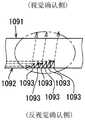
如图21、22所示,在比第十实施方式的显示板20更靠视觉确认侧设置有透光板1090。透光板1090例如通过聚碳酸酯树脂树脂或丙烯酸树脂等合成树脂形成为透光性的平板状。透光板1090具有朝向视觉确认侧的表板面1091以及朝向反视觉确认侧的背板面1092。As shown in FIGS. 21 and 22 , a light-transmittingplate 1090 is provided on the visual confirmation side of thedisplay panel 20 of the tenth embodiment. The light-transmittingplate 1090 is formed in a light-transmitting flat plate shape with synthetic resin such as polycarbonate resin resin or acrylic resin, for example. The light-transmittingplate 1090 has afront surface 1091 facing the visual confirmation side and aback surface 1092 facing the opposite visual confirmation side.

如图23、24所示,可视光源部1030具有多个可视发光元件1031,该可视发光元件以与透光板1090的外边缘部对置的方式安装于照明基板1032。各可视发光元件1031沿着透光板1090的外边缘部排列。各可视发光元件1031发出作为可视光的可视光源光,并提供到透光板1090的板内部。As shown in FIGS. 23 and 24 , the visible light source unit 1030 includes a plurality of visible light emitting elements 1031 , and the visible light emitting elements are attached to thelighting substrate 1032 so as to face the outer edge portion of thetranslucent plate 1090 . The visible light-emitting elements 1031 are arranged along the outer edge of the light-transmittingplate 1090 . Each visible light-emitting element 1031 emits visible light source light as visible light, and supplies it to the inside of the light-transmittingplate 1090 .

与这样的可视光源光向板内部的导入对应地形成有透光板1090。具体地,如图25所示,透光板1090是从背板面1092向表板面1091侧凹陷而形成的元件,具有凹陷深度5~20μm左右的微小的尺寸的多个反射元件1093。通过将多个反射元件1093适当地配置于背板面1092上,来形成图案PTN。各反射元件1093使被导入到板内部的可视光源光向视觉确认侧反射,从而图案PTN基于微小的反射元件1093的集合以面状发光,并被显示。特别是本实施方式的图案PTN成为以对指针40a、40b的显示以及图像显示器10的显示画面11进行镶边的方式被视觉确认的框状的框图案。A light-transmittingplate 1090 is formed corresponding to the introduction of such visible light source light into the inside of the plate. Specifically, as shown in FIG. 25 , the light-transmittingplate 1090 is an element formed by being recessed from theback surface 1092 to thefront surface 1091 side, and has a plurality ofreflective elements 1093 having a small size of about 5 to 20 μm indentation depth. The pattern PTN is formed by appropriately arranging a plurality ofreflective elements 1093 on thebackplane surface 1092 . Eachreflection element 1093 reflects the visible light source light introduced into the board toward the visual confirmation side, so that the pattern PTN emits light in a planar shape based on the group ofminute reflection elements 1093 and is displayed. In particular, the pattern PTN of the present embodiment is a frame-shaped frame pattern visually recognized so as to border the display of thepointers 40 a and 40 b and thedisplay screen 11 of theimage display 10 .

在第十实施方式中,如图23所示,近红外光照射部1080具有近红外发光元件1081,该近红外发光元件1081被配置为夹设于在可视光源部1030中相互并排的可视发光元件1031间。In the tenth embodiment, as shown in FIG. 23 , the near-infrared light emitting section 1080 includes a near-infrared light-emitting element 1081 arranged to be interposed between the visible light sources 1030 arranged side by side in the visible light source section 1030 . Between the light-emitting elements 1031.

因此,可视光源光和包括可视上限光的近红外光这两方都入射到透光板1090的外边缘部。这样在透光板1090的板内部中,可视显示光和包括可视上限光的近红外光混合的状态下,被反射元件1093反射,发光照射到视觉确认侧。此外,在图23~25中,用实线的箭头示意性地示出可视光源光的一部分,用虚线的箭头示意性地示出包括可视上限光的近红外光的一部分。Therefore, both the visible light source light and the near-infrared light including the visible upper limit light are incident on the outer edge portion of the light-transmittingplate 1090 . In this way, in the inside of the light-transmittingplate 1090 , the visible display light and the near-infrared light including the visible upper limit light are mixed, and are reflected by thereflective element 1093 to emit light to the visual confirmation side. In addition, in FIGS. 23 to 25 , a part of the visible light source light is schematically shown by a solid-line arrow, and a part of the near-infrared light including the visible upper limit light is schematically shown by a broken-line arrow.

这样,近红外光照射部1080照射的光中有可能被视觉确认的可视上限光被伪装成限制被识别为单独存在的光。即,在本实施方式中,可视光源部1030以及透光板1090作为对可视上限光进行伪装的伪装部1003发挥作用。In this way, among the lights irradiated by the near-infrared light irradiating section 1080 , the upper limit of visible light, which may be visually recognized, is disguised as limiting the light recognized as being alone. That is, in the present embodiment, the visible light source unit 1030 and the light-transmittingplate 1090 function as the camouflage unit 1003 for camouflaging the visible upper limit light.

根据以上说明的第十实施方式,通过将近红外光照射部1080配置于可视光源部1030,从而使反射元件1093反射包括可视光的上限的波长的光的近红外光,并照射到视觉确认侧。即,可视上限光通过与由反射元件1093实现的图案PTN的显示混合而被伪装,所以即使乘员视觉确认图案PTN,也能够提高只识别为仅图案PTN发光的可能性,并能够抑制复杂的印象。According to the tenth embodiment described above, by arranging the near-infrared light irradiating section 1080 in the visible light source section 1030, thereflection element 1093 reflects the near-infrared light including the light of the wavelength of the upper limit of the visible light, and irradiates it to the visible light. side. That is, the visible upper limit light is camouflaged by being mixed with the display of the pattern PTN realized by thereflective element 1093. Therefore, even if the occupant visually recognizes the pattern PTN, it is possible to increase the possibility of recognizing that only the pattern PTN emits light, and it is possible to suppress complicated complications. impression.

(第十一实施方式)(Eleventh Embodiment)

如图26所示,第十一实施方式是第一实施方式的变形例。以与第一实施方式不同的点为中心对第十一实施方式进行说明。As shown in FIG. 26 , the eleventh embodiment is a modification of the first embodiment. The eleventh embodiment will be described focusing on the points different from the first embodiment.

第十一实施方式的车辆用显示装置1100是具备图像显示器1110、透光性罩部1113、光学贴合部1115、导光部件1117以及近红外光照射部1080等的图形仪表。Thevehicle display device 1100 according to the eleventh embodiment is a graphic instrument including an image display 1110 , a translucent cover part 1113 , an optical bonding part 1115 , alight guide member 1117 , a near-infrared light irradiation part 1080 , and the like.

对图像进行发光显示的图像显示器1110成为与第一实施方式同样的液晶显示器。在图像显示器1110的内部设置有用于图像的显示的电极、布线、彩色滤光片以及荧光体等部件。The image display 1110 that emits light and displays an image is a liquid crystal display similar to that of the first embodiment. Components such as electrodes, wirings, color filters, and phosphors for displaying images are provided inside the image display 1110 .

透光性罩部1113例如由聚碳酸酯树脂树脂或丙烯酸树脂等合成树脂或玻璃构成,形成为透光性的平板状。透光性罩部1113在比图像显示器1110更靠视觉确认侧与该图像显示器1110的显示画面1111之间隔开规定的间隔配置。The translucent cover portion 1113 is made of synthetic resin such as polycarbonate resin resin or acrylic resin, or glass, for example, and is formed in a translucent flat plate shape. The translucent cover portion 1113 is arranged at a predetermined interval on the visual confirmation side of the image display 1110 and thedisplay screen 1111 of the image display 1110 .

光学贴合部1115通过以填埋显示画面1111与透光性罩部1113之间的缝隙的方式将透光性的媒介物填充到该缝隙而形成。作为透光性的媒介物,采用光学用透明树脂(Optically Clear Resin,OCR)。光学贴合部1115形成为具有与上述的规定的间隔对应的0.5~3.0mm左右的厚度的层状。由此,抑制在外光向显示画面1111入射时,该外光在透光性罩部1113与显示画面1111之间多重反射,图像的可视性提高。The optical bonding part 1115 is formed by filling the gap between thedisplay screen 1111 and the translucent cover part 1113 with a translucent medium so as to fill the gap. As a light-transmitting medium, Optically Clear Resin (OCR) is used. The optical bonding portion 1115 is formed in a layered shape having a thickness of about 0.5 to 3.0 mm corresponding to the above-mentioned predetermined interval. Thereby, when external light is incident on thedisplay screen 1111 , the external light is suppressed from being repeatedly reflected between the translucent cover portion 1113 and thedisplay screen 1111 , and the visibility of the image is improved.

导光部件1117形成为例如由聚碳酸酯树脂树脂或丙烯酸树脂等合成树脂构成的透光性。在导光部件1117中将导入部1118配置为与在比图像显示器1110更靠反视觉确认侧配置的基板9对置,该导入部1118构成为能够将光导入到部件内部。另外,在导光部件1117中,将导出部1119配置为与光学贴合部1115的端部连接,该导出部1119构成为能够从部件内部导出光。Thelight guide member 1117 is formed to be translucent, for example, made of a synthetic resin such as polycarbonate resin resin or acrylic resin. In thelight guide member 1117, anintroduction portion 1118 is arranged so as to face thesubstrate 9 arranged on the opposite side than the image display 1110, and theintroduction portion 1118 is configured to be able to guide light into the member. Moreover, in thelight guide member 1117, the lead-outpart 1119 is arrange|positioned so that it may connect with the edge part of the optical bonding part 1115, and this lead-outpart 1119 is comprised so that light may lead out from the inside of a member.

在第十一实施方式中,近红外光照射部980具有多个近红外发光元件1181,该多个近红外发光元件1181配置在基板9的视觉确认侧中,与导光部件1117的导入部1118对置的位置。In the eleventh embodiment, the near-infrared light irradiating section 980 has a plurality of near-infrared light-emitting elements 1181 arranged on the visual confirmation side of thesubstrate 9 , in contact with theintroduction section 1118 of thelight guide member 1117 . Opposite position.

因此,从近红外发光元件1181发出的包括可视上限光的近红外光通过导入部1118在导光部件1117的部件内部被导光,并从导出部1119供给到光学贴合部1115的内部。Therefore, the near-infrared light including the visible upper limit light emitted from the near-infrared light-emitting element 1181 is guided inside thelight guide member 1117 by theintroduction portion 1118 , and is supplied from the lead-out portion 1119 to the inside of the optical bonding portion 1115 .

那样的话,包括可视上限光的近红外光从光学贴合部1115进入到图像显示器1110的内部,通过电极、布线、彩色滤光片以及荧光体等部件接受扩散作用。其结果基于图像显示器1110的图像的发光显示的可视显示光和包括可视上限光的近红外光在被混合的状态下向视觉确认侧照射。此外,在图26中,用实线的箭头示意性地示出可视光源光的一部分,用虚线的箭头示意性地示出包括可视上限光的近红外光的一部分。In that case, the near-infrared light including the visible upper limit light enters the interior of the image display 1110 from the optical bonding portion 1115, and is diffused through components such as electrodes, wirings, color filters, and phosphors. As a result, the visible display light based on the light-emitting display of the image of the image display 1110 and the near-infrared light including the visible upper limit light are irradiated to the visual confirmation side in a mixed state. In addition, in FIG. 26 , a part of the visible light source light is schematically shown by a solid-line arrow, and a part of the near-infrared light including the visible upper limit light is schematically shown by a broken-line arrow.

根据以上,图像显示器1110、透光性罩部1113以及光学贴合部1115等构成通过可视显示光的发光显示信息的发光显示部1102。而且,近红外光照射部1180照射的光中有可能被视觉确认的可视上限光被伪装成限制被识别为单独存在的光。即,在本实施方式中,图像显示器1110、透光性罩部1113以及光学贴合部1115作为对可视上限光进行伪装的伪装部1103发挥作用。As described above, the image display 1110 , the translucent cover portion 1113 , the optical bonding portion 1115 , and the like constitute the light-emitting display portion 1102 that displays information by light-emitting visible display light. Furthermore, the upper limit of visible light that can be visually recognized among the lights irradiated by the near-infrared light irradiating unit 1180 is disguised to limit the light recognized as being alone. That is, in this embodiment, the image display 1110, the translucent cover part 1113, and the optical bonding part 1115 function as the camouflage part 1103 which camouflages the visible upper limit light.

根据以上说明的第十一实施方式,近红外光照射部1180向光学贴合部1115供给包括可视上限光的近红外光。向光学贴合部1115供给的包括可视上限光的近红外光通过与从图像显示器1110发出的可视显示光混合而被伪装。因而,即使乘员视觉确认图像显示器1110,也能够提高只识别为仅显示图像的可能性,并能够抑制复杂的印象。According to the eleventh embodiment described above, the near-infrared light irradiation unit 1180 supplies the near-infrared light including the visible upper limit light to the optical bonding unit 1115 . The near-infrared light including the visible upper limit light supplied to the optical bonding portion 1115 is camouflaged by being mixed with the visible display light emitted from the image display 1110 . Therefore, even if the occupant visually confirms the image display 1110, the possibility of recognizing that only the image is displayed can be increased, and a complicated impression can be suppressed.

以上,如通过多个实施方式所说明那样,伪装部活用显示板的指标、指针、加饰用的环等具有车辆用显示装置现有的功能的部件,通过对这些部件附加伪装功能来对可视上限光进行伪装。As described above in the various embodiments, the camouflage portion utilizes components having existing functions of a vehicle display device, such as indicators, pointers, and decorative rings of the display panel, and adding a camouflage function to these components allows camouflage according to the upper limit of light.

以上,对多个实施方式进行了说明,但本公开并不解释为限定为那些实施方式,能够在不脱离本公开的要旨的范围内应用于各种实施方式以及组合。A plurality of embodiments have been described above, but the present disclosure is not to be construed as being limited to those embodiments, and can be applied to various embodiments and combinations without departing from the gist of the present disclosure.

具体地,作为变形例1,也可以通过设置于显示板20并显示警告等的显示灯形成红系色显示区域DAr,从该红系色显示区域DAr在混合了包括可视上限光的近红外光的状态下发出作为可视显示光的红色显示光。Specifically, as Modification 1, a red-based color display area DAr may be formed by a display lamp provided on thedisplay panel 20 to display a warning or the like, and from the red-based color display area DAr, near-infrared light including visible upper limit light may be mixed. In the light state, red display light as visible display light is emitted.

作为变形例2,也可以在设置于车辆用显示装置100的操作开关形成白色显示区域DAw、红系色显示区域DAr或者黄绿色显示区域DAg等显示区域DA,从这些显示区域DA在混合了包括可视上限光的近红外光的状态下发出可视显示光。AsModification 2, a display area DA such as a white display area DAw, a red-colored display area DAr, or a yellow-green display area DAg may be formed on the operation switch provided in thevehicle display device 100, and the display areas DA may be mixed with the Visible display light is emitted in the state of near-infrared light of visible upper limit light.

作为与第二、四实施方式有关的变形例3,伪装部203等作为构成要素的黄绿色显示区域Dag并不限于环保显示灯226、发光环250等显示燃料效率的显示。例如,显示区域Dag也可以是显示电动汽车等的行驶状态或者充电状态的能量管理显示。As a third modification related to the second and fourth embodiments, the yellow-green display area Dag as a component of thecamouflage portion 203 is not limited to the display of fuel efficiency such as the eco indicator lamp 226 and the light ring 250 . For example, the display area Dag may be an energy management display that displays the running state or charging state of an electric vehicle or the like.

作为与第四实施方式有关的变形例4,近红外光照射部408也可以与背光灯采用黄绿色波长光的液晶显示器,或者使用了荧光显示管的VFD(Vacuum fluorescent display:真空荧光显示器)相邻配置。AsVariation 4 of the fourth embodiment, the near-infrared light irradiating portion 408 may be compatible with a liquid crystal display using yellow-green wavelength light as a backlight, or a VFD (Vacuum fluorescent display) using a fluorescent display tube. neighbor configuration.

作为与第五、六实施方式有关的变形例5,作为外光反射部,也可以采用形成在显示板520、620上的金属线。As amodification 5 of the fifth and sixth embodiments, metal wires formed on the display panels 520 and 620 may be used as the external light reflecting portions.

作为与第七实施方式有关的变形例6,红系色加饰部并不限于红系色环750,也可以通过在显示板720上设置利用遮光性印刷而形成的红系色层来形成。As Modification Example 6 of the seventh embodiment, the red-based color decoration portion is not limited to the red-basedcolor ring 750 , and may be formed by providing a red-based color layer formed by light-shielding printing on thedisplay panel 720 .

作为变形例7,也可以通过设置利用遮光性印刷而形成的红系色层来形成刻度指标23a、23b的至少一部分,并与该刻度指标23a、23b的至少一部分相邻配置近红外光照射部80。AsModification 7, at least a part of thescale indexes 23a and 23b may be formed by providing a red color layer formed by light-shielding printing, and the near-infrared light irradiating part may be arranged adjacent to at least a part of thescale indexes 23a and 23b. 80.

作为与第八实施方式有关的变形例8,加饰用发光元件831也可以构成为发出红系色光或者黄绿色波长光作为可视加饰光。As a modification example 8 related to the eighth embodiment, the decorative light-emitting element 831 may be configured to emit red light or yellow-green wavelength light as visible decorative light.

作为与第九实施方式有关的变形例9,也可以采用轴内导光方式的指针940。在图27、28所示的例子中,在指针940的连结部941中突出形成有贯通步进电机43的内部的贯通轴941c。贯通轴941c也作为步进电机43的旋转轴发挥作用。在贯通轴941c中贯通步进电机43从步进电机43露出的前端部成为使可视显示光以及近红外光入射到贯通轴941c的内部的入射部941a。As the ninth modification of the ninth embodiment, thepointer 940 of the in-axis light guide system may be used. In the example shown in FIGS. 27 and 28 , a throughshaft 941 c penetrating the inside of the steppingmotor 43 is formed to protrude from the connectingportion 941 of thepointer 940 . The throughshaft 941c also functions as a rotation shaft of the steppingmotor 43 . The distal end portion of thepenetration shaft 941c exposed from the steppingmotor 43 through the steppingmotor 43 is anincident portion 941a that allows visible display light and near-infrared light to enter thepenetration shaft 941c.

而且,来自配置在基板9上的显示用发光元件931的可视显示光、和来自近红外发光元件981的包括可视上限光的近红外光在混合的状态下向入射部941a入射,在贯通轴941c中被导光到视觉确认侧的指示部942。Then, the visible display light from the display light-emittingelement 931 arranged on thesubstrate 9 and the near-infrared light including the visible upper limit light from the near-infrared light-emitting element 981 enter theincident portion 941a in a mixed state, In theshaft 941c, light is guided to theindicator portion 942 on the visual confirmation side.

作为与第九实施方式有关的变形例10,显示用发光元件931也可以发出黄绿色波长光或者白色光作为可视显示光。As amodification 10 of the ninth embodiment, the light-emittingelement 931 for display may emit yellow-green wavelength light or white light as visible display light.

作为与第十实施方式有关的变形例11,反射元件1093也可以不形成为从背板面1092凹陷。例如,能够通过在板面1092印刷光学墨水来形成反射元件1093。AsModification 11 related to the tenth embodiment, thereflection element 1093 may not be formed so as to be recessed from theback plate surface 1092 . For example, thereflective element 1093 can be formed by printing optical ink on theboard surface 1092 .

作为与第十实施方式有关的变形例12,多个反射元件1093也可以不是形成为微小的尺寸,并基于该反射元件1093的集合显示以面状发光的图案PTN的构成。例如,反射元件1093也可以是具有侧壁面,且该侧壁面反射可视光源光以及包括可视上限光的近红外光而发光的结构,该侧壁面将其凹陷深度例如设定为0.3~1.0mm的范围,并以轮廓显示信息的方式形成为刻度或者数字等的形状。As a twelfth modification of the tenth embodiment, the plurality ofreflection elements 1093 may not be formed in a minute size, and the pattern PTN that emits light in a planar shape may be displayed based on the aggregation of thereflection elements 1093 . For example, thereflective element 1093 may have a sidewall surface, and the sidewall surface reflects the visible light source light and the near-infrared light including the upper limit of visible light to emit light, and the sidewall surface has a recessed depth of, for example, 0.3-1.0 The range of mm is formed into a shape such as a scale or a number so that information is displayed in outline.

作为与第十实施方式有关的变形例13,也可以图案PTN显示信息,可视光源部1030以及透光板1090作为通过可视显示光的发光显示该信息的发光显示部发挥作用。As a modification 13 of the tenth embodiment, information may be displayed by pattern PTN, and the visible light source unit 1030 and thelight transmitting plate 1090 function as a light-emitting display unit that displays the information by emitting visible display light.

作为变形例14,也可以采用包括自发光的荧光体、蓄光体、发出紫外线光可视光的元件、发出包括紫外线光的可视光的涂料等,来代替采用发光二极管的显示用发光元件31。As Modification 14, instead of the light-emitting element 31 for display using a light-emitting diode, it is also possible to use a phosphor, a light-storage body that emits light by itself, an element that emits visible light including ultraviolet light, a paint that emits visible light including ultraviolet light, and the like. .

作为变形例15,拍摄部60也可以配置在车辆用显示装置100的内部中图像显示器10的旁边以外的位置。另外,拍摄系统4中近红外光照射部80也可以配置在车辆用显示装置100的内部,拍摄部60以及图像处理部70中的至少一部分配置在与车辆用显示装置100不同的外部。As a fifteenth modification, theimaging unit 60 may be arranged in a position other than the side of theimage display 10 in the interior of thevehicle display device 100 . In theimaging system 4 , the near-infraredlight irradiating unit 80 may be arranged inside thevehicle display device 100 , and at least a part of theimaging unit 60 and the image processing unit 70 may be arranged outside thevehicle display device 100 .

作为变形例16,拍摄部60的拍摄对象并不限于乘员的面部。例如可以将拍摄对象设为手臂,并判定乘员的手势操作输入、脉搏等身体状况。As Modification 16, the imaging object of theimaging unit 60 is not limited to the occupant's face. For example, it is possible to set the photographing object as the arm, and determine the occupant's gesture operation input, pulse and other physical conditions.

(第十二实施方式)(Twelfth Embodiment)

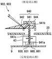
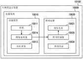
根据本公开的第十二实施方式的照明装置10020搭载在车辆上,发出用于拍摄车辆的乘员的照明光。照明装置10020与拍摄装置10010等一起构成拍摄系统10009。本实施方式的拍摄系统10009被利用于将车辆的乘员,特别是驾驶员的面部作为拍摄对象进行拍摄,并对该图像进行处理,从而监视驾驶员的瞌睡、漫不经心等状态的驾驶员状态监控(DriverStatus Monitor,DSM)。Thelighting device 10020 according to the twelfth embodiment of the present disclosure is mounted on a vehicle, and emits illumination light for photographing an occupant of the vehicle. Thelighting device 10020 constitutes a photographingsystem 10009 together with the photographingdevice 10010 and the like. Theimaging system 10009 of the present embodiment is used for driver state monitoring ( DriverStatus Monitor, DSM).

如图29所示,本实施方式的照明装置10020配置在与拍摄系统10009一体地形成的车辆用显示装置10100的内部。因此,照明装置10020与车辆用显示装置10100一起设置在与作为视觉确认者的乘员就坐的座席对置的中控面板。As shown in FIG. 29 , thelighting device 10020 of the present embodiment is arranged inside thevehicle display device 10100 which is integrally formed with theimaging system 10009 . Therefore, thelighting device 10020 is installed on the center console facing the seat on which the occupant, who is the visual observer, sits, together with thevehicle display device 10100 .

车辆用显示装置10100构成组合了基于指针10060指示指标10042的模拟显示、和基于图像显示器10038显示的图像的数字显示的组合仪表,朝向视觉确认侧显示信息。作为被显示的信息,例如列举车辆的速度、发动机转速、燃料余量、发动机冷却水的水温、电动马达的电流值、其它车辆的异常等车辆的状态。作为其它被显示的信息,例如列举警报、道路信息、视野辅助信息、电子邮件等各种信息。Thevehicle display device 10100 constitutes an instrument cluster combining an analog display based on thepointer 10060 indicating theindex 10042 and a digital display based on an image displayed on theimage display 10038, and displays information toward the visual confirmation side. The displayed information includes, for example, the speed of the vehicle, the engine speed, the remaining fuel level, the water temperature of the engine cooling water, the current value of the electric motor, and the state of the vehicle such as abnormality of other vehicles. As other displayed information, various information such as warning, road information, visual aid information, and e-mail are listed, for example.

这样的车辆用显示装置10100除了图像显示器10038、显示板10040、显示用光源部10050以及指针10060之外,还由拍摄系统10009等构成。Such avehicle display device 10100 is constituted by animaging system 10009 and the like in addition to theimage display 10038 , thedisplay panel 10040 , the display light source unit 10050 , and thepointer 10060 .

图像显示器10038配置在车辆用显示装置10100的大致中央。在本实施方式中,图像显示器10038成为是使用了薄膜晶体管(Thin Film Transistor,TFT)的透射式的液晶面板,采用了由在二维方向上排列的多个液晶像素形成的有源矩阵型的液晶面板的液晶显示器。此外,作为图像显示器10038,也可以采用液晶显示器以外的有机EL显示器等。Theimage display 10038 is arranged substantially in the center of thevehicle display device 10100 . In the present embodiment, theimage display 10038 is a transmissive liquid crystal panel using a thin film transistor (TFT), and an active matrix type liquid crystal panel formed of a plurality of liquid crystal pixels arranged two-dimensionally is used. LCD panel LCD display. Further, as theimage display 10038, an organic EL display or the like other than a liquid crystal display may be used.

显示板10040一般被称为文字板,是在车辆用显示装置10100中在视觉确认侧形成为筒状的饰板以及封闭饰板的视觉确认侧开口部的透明板围起的空间露出的露出部件。显示板10040例如通过对由聚碳酸酯树脂树脂或丙烯酸树脂等合成树脂构成的透光性的基材的表面部分地或者整体实施半透光性或者遮光性的印刷而形成为平板状。此外,也可以代替印刷而实施涂装,也可以通过粘贴等将使近红外光透过的光学树脂或者光学滤光材料保持在显示板10040上。Thedisplay panel 10040 is generally referred to as a dial, and is an exposed member exposed in a space surrounded by a trim panel formed in a cylindrical shape on the viewing side of thevehicle display device 10100 and a transparent plate that closes an opening on the viewing side of the trim panel. . Thedisplay panel 10040 is formed into a flat plate shape by, for example, partially or entirely applying semi-translucent or light-shielding printing to the surface of a translucent base material made of a synthetic resin such as polycarbonate resin resin or acrylic resin. In addition, instead of printing, coating may be applied, and an optical resin or an optical filter material that transmits near-infrared light may be held on thedisplay panel 10040 by sticking or the like.

显示板10040配置在比图像显示器10038更靠视觉确认侧。在显示板10040中与图像显示器10038重叠的位置上例如开有开口孔10041,图像被显示于视觉确认侧,而不会干扰显示板10040。在显示板10040中,在夹着图像显示器10038的左右区域中分别形成有由指针10060指示的指标10042。通过可视光源部从与视觉确认侧相反侧(以下,称为反视觉确认侧)照明显示板10040的指标10042。Thedisplay panel 10040 is arranged on the visual confirmation side rather than theimage display 10038 . In thedisplay panel 10040 , for example, anopening hole 10041 is formed at a position overlapping theimage display 10038 , and the image is displayed on the visual confirmation side without disturbing thedisplay panel 10040 . In thedisplay panel 10040,indicators 10042 indicated by thepointers 10060 are formed in the left and right regions sandwiching theimage display 10038, respectively. Theindicator 10042 of thedisplay panel 10040 is illuminated by the visible light source from the side opposite to the visual confirmation side (hereinafter, referred to as the reverse visual confirmation side).

如图30所示,显示用光源部10050配置在比显示板10040更靠反视觉确认侧,具有发出可视显示光的多个显示用发光元件10051。各显示用发光元件10051例如采用发光二极管元件,各显示用发光元件10051通过基板10070上的导通图案与电源连接,从而朝向显示板10040发出可视显示光。特别是在本实施方式中,作为各显示用发光元件10051,采用由在400~800nm左右的波长的范围中广泛分布的光构成的白色光。As shown in FIG. 30 , the light source unit 10050 for display is arranged on the opposite side of thedisplay panel 10040 and has a plurality of light-emitting elements 10051 for display that emit visible display light. Each display light-emitting element 10051 is, for example, a light-emitting diode element, and each display light-emitting element 10051 is connected to a power source through a conduction pattern on thesubstrate 10070 to emit visible display light toward thedisplay panel 10040 . In particular, in the present embodiment, as each display light-emitting element 10051, white light composed of light widely distributed in a wavelength range of about 400 to 800 nm is used.

在显示板10040上,通过上述的印刷形成有遮光区域SA以及显示区域DA。遮光区域SA占据显示板10040的大多数的面积,例如通过遮光性的印刷形成暗色(例如黑色),从而对来自反视觉确认侧的可视显示光进行遮光。显示区域DA通过不实施半透光性的印刷或不实施印刷,而使来自反视觉确认侧的可视光源光透过,并通过将指标10042设定在显示区域DA,而使该指标10042发光,并被显示。On thedisplay panel 10040, the light shielding area SA and the display area DA are formed by the above-mentioned printing. The light-shielding area SA occupies most of the area of thedisplay panel 10040, and is formed in a dark color (eg, black) by, for example, light-shielding printing, thereby shielding the visible display light from the anti-visual confirmation side. The display area DA transmits the light from the visible light source from the anti-visual confirmation side by not performing semi-translucent printing or printing, and sets theindicator 10042 in the display area DA, so that theindicator 10042 emits light , and is displayed.

分别与显示板10040的左右区域对应地设置多个指针10060。特别是在本实施方式中,指针10060在左右区域中各设置一个。各指针10060一体地具有连结部10061以及指示部10062。连结部10061配置在比显示板10040更靠反视觉确认侧,并与保持在平板状的基板上的步进电机10063的旋转轴连结。指示部10062配置在比显示板10040更靠视觉确认侧,通过呈针状,从而能够指示指标10042。A plurality ofpointers 10060 are provided corresponding to the left and right regions of thedisplay panel 10040, respectively. In particular, in this embodiment, onepointer 10060 is provided in each of the left and right regions. Eachpointer 10060 has a connectingportion 10061 and an indicatingportion 10062 integrally. The connectingportion 10061 is arranged on the opposite side to the visual confirmation side than thedisplay panel 10040, and is connected to the rotating shaft of the steppingmotor 10063 held on the flat substrate. Theindicator 10062 is arranged on the visual confirmation side than thedisplay panel 10040, and can indicate theindicator 10042 by being in the shape of a needle.

各指针10060根据步进电机10063的输出而绕指针轴转动,通过分别指示对应的指标10042,从而显示与指示位置对应的信息。特别是在本实施方式中,通过左侧的指针10060以及指标10042显示车辆的速度,通过右侧的指针10060以及指标10042显示车辆的发动机转速。Eachpointer 10060 rotates around the pointer axis according to the output of the steppingmotor 10063, and by respectively indicating the correspondingindex 10042, information corresponding to the indicated position is displayed. In particular, in the present embodiment, the speed of the vehicle is displayed by thepointer 10060 and theindicator 10042 on the left, and the engine speed of the vehicle is displayed by thepointer 10060 and theindicator 10042 on the right.

如图31所示,拍摄系统10009由拍摄装置10010以及照明装置10020等构成。拍摄装置10010对车辆的乘员(特别是在本实施方式中驾驶员的面部)进行拍摄。具体地,如图32所示,拍摄装置10010具有相机10011、相机罩部10013以及图像处理部10014。相机10011配置在比显示板10040更靠反视觉确认侧的、例如图像显示器10038的旁边。As shown in FIG. 31 , theimaging system 10009 includes animaging device 10010 , anillumination device 10020 , and the like. The photographingdevice 10010 photographs the occupant of the vehicle (especially, the driver's face in the present embodiment). Specifically, as shown in FIG. 32 , theimaging device 10010 includes acamera 10011 , acamera cover unit 10013 , and animage processing unit 10014 . Thecamera 10011 is arranged on the opposite side to the visual confirmation side than thedisplay panel 10040, for example, next to theimage display 10038.

相机10011具有检测元件10011a、以及用于在检测元件10011a上对拍摄对象进行成像的透镜10011b。作为检测元件10011a,例如采用CMOS传感器等从可视光到可视光的上限的波长的光(包括近红外光)具有良好的灵敏度,且检测的像的分辨率较高的元件。此处,可视光的上限的波长的光(以下,称为可视上限光)意味着接近780~830nm的人能够视觉确认的上限的波长的光Thecamera 10011 has a detection element 10011a, and alens 10011b for imaging a photographic subject on the detection element 10011a. As the detection element 10011a, for example, a CMOS sensor or the like is used which has a good sensitivity and a high resolution of a detected image at wavelengths ranging from visible light to the upper limit of visible light (including near-infrared light). Here, light with a wavelength of the upper limit of visible light (hereinafter referred to as visible upper limit light) means light with a wavelength close to the upper limit that can be visually recognized by a person of 780 to 830 nm

在显示板10040中与相机10011对置的位置例如通过印刷设置近红外光透过滤光层10043,从而将从视觉确认侧覆盖相机10011的相机罩部10013形成为平板状。近红外光透过滤光层10043使包括可视上限光的近红外光透过,并且将比可视上限光短波长的可视光的透过率设定得较低,从而能够通过检测元件检测包括可视上限光的近红外光,使得从视觉确认侧的乘员无法清楚地视觉确认相机。Thecamera cover 10013 covering thecamera 10011 from the visual confirmation side is formed into a flat plate shape by providing, for example, a near-infrared light transmittingfilter layer 10043 at a position facing thecamera 10011 on thedisplay panel 10040 . The near-infrared light-transmittingfilter layer 10043 transmits near-infrared light including the visible upper limit light, and sets the transmittance of visible light with a wavelength shorter than the visible upper limit light to be lower, so that the detection element can detect it. The near-infrared light including the visible upper limit light makes it impossible to visually confirm the camera clearly from the occupant on the visual confirmation side.

图像处理部10014被实现为以将至少一个处理器、存储器、输入输出接口等安装在基板10070上的电子电路为主体而构建的功能模块。处理器通过基于通过输入输出接口输入的来自检测元件的信号来执行存储器中存储的计算机程序,从而能够实施图像处理。更详细而言,图像处理部10041根据从检测元件10000a输入的信号来生成拍摄拍摄对象而获得的图像数据。生成的图像数据保持原样地被输出至车辆的ECU(Electric Control Unit:电子控制单元)等车辆用显示装置10100的外部,可以由该ECU进行解析,也可以由图像处理部10014对图像数据进行解析,并判定驾驶员的瞌睡或漫不经心的有无。Theimage processing unit 10014 is implemented as a functional module mainly composed of an electronic circuit in which at least one processor, a memory, an input/output interface, and the like are mounted on thesubstrate 10070 . The processor can implement image processing by executing the computer program stored in the memory based on the signal from the detection element input through the input-output interface. More specifically, theimage processing unit 10041 generates image data obtained by photographing a subject based on a signal input from the detection element 10000a. The generated image data is output as it is to the outside of thevehicle display device 10100 such as an ECU (Electric Control Unit) of the vehicle, and the ECU may analyze the image data, or theimage processing unit 10014 may analyze the image data. , and determine whether the driver is drowsy or inattentive.

如图33所示,照明装置10020通过照明光照明由拍摄装置10010拍摄的乘员。照明装置10020具有面发光部10021、照明罩部10030以及照明控制部10035。面发光部10021配置在车辆用显示装置10100中比显示板10040更靠反视觉确认侧的与可视光源部隔开遮光壁10071划分出的空间。As shown in FIG. 33 , the illuminatingdevice 10020 illuminates the occupant photographed by the photographingdevice 10010 with illumination light. Thelighting device 10020 includes a surface light-emittingunit 10021 , alighting cover unit 10030 , and alighting control unit 10035 . The surface light-emittingportion 10021 is arranged in thevehicle display device 10100 in a space partitioned by the light-shieldingwall 10071 from the visible light source portion on the side of thedisplay panel 10040 on the opposite side for confirmation.

在显示板10040中与面发光部10021对置的位置设置近红外光透过滤光层10044,从而将从视觉确认侧覆盖面发光部10021的照明罩部10030形成为平板状。近红外光透过滤光层10044与相机罩部10013同样地,使包括可视上限光的近红外光透过,并将比可视上限光短波长的可视光的透过率设定得较低。A near-infrared light-transmittingfilter layer 10044 is provided on thedisplay panel 10040 at a position facing the surface light-emittingportion 10021, so that theillumination cover portion 10030 covering the surface light-emittingportion 10021 from the visual confirmation side is formed into a flat plate shape. The near-infrared light-transmittingfilter layer 10044 transmits near-infrared light including the visible upper limit light, similarly to thecamera cover portion 10013, and sets the transmittance of visible light having a shorter wavelength than the visible upper limit light. Low.

另外,在本实施方式的照明罩部10030中,在车辆用显示装置10100的空间中露出的视觉确认侧表面被实施与作为车辆用显示装置10100的周边部件的中控面板、转向部件,或者仪表罩的表面加工相匹配的由凹凸构成的加饰花纹。此外,加饰花纹可以通过印刷或者薄膜的粘贴来实施,该情况下,例如可以采用金属色调、碳色调和木纹色调等加饰花纹。通过这样的加饰花纹,照明罩部10030的美观与上述的周边部件的美观之差变小,使照明装置10020的存在难以引人注目。In addition, in thelighting cover part 10030 of the present embodiment, the visual confirmation side surface exposed in the space of thevehicle display device 10100 is implemented with a center control panel, a steering member, or a meter as peripheral parts of thevehicle display device 10100 The surface of the cover is processed to match the decorative pattern composed of concave and convex. In addition, the decorative pattern may be implemented by printing or film sticking, and in this case, for example, decorative patterns such as metallic tone, carbon tone, and wood grain tone can be adopted. With such a decorative pattern, the difference between the appearance of thelighting cover portion 10030 and the appearance of the peripheral components described above is reduced, and the presence of thelighting device 10020 is less noticeable.

面发光部10021具有近红外发光元件10022以及面发光化光学元件10023。近红外发光元件10022例如采用发光二极管。近红外发光元件10022被保持在基板10070的视觉确认侧表面,通过基板10070上的导通图案与电源连接,从而发出包括可视上限光的近红外光。特别是在本实施方式中,例如采用在850nm具有峰值波长,半值宽度具有30~40nm左右的波长特性的近红外发光元件10022。The surface light-emittingportion 10021 includes a near-infrared light-emittingelement 10022 and a surface-emittingoptical element 10023 . As the near-infrared light-emittingelement 10022, a light-emitting diode is used, for example. The near-infrared light-emittingelement 10022 is held on the visual confirmation side surface of thesubstrate 10070, and is connected to a power source through a conduction pattern on thesubstrate 10070, thereby emitting near-infrared light including visible upper limit light. In particular, in the present embodiment, a near-infrared light-emittingelement 10022 having a peak wavelength at 850 nm and wavelength characteristics of about 30 to 40 nm in a half-value width is used, for example.

面发光化光学元件10023是配置在近红外发光元件10022与照明罩部10030之间,例如以由聚碳酸酯树脂树脂或丙烯酸树脂等合成树脂构成的透光性的基材为主体而形成的棱镜透镜。面发光化光学元件10023具有将来自近红外发光元件10022的包括可视上限光的近红外光导入的导入部10024、以及对导入到导入部10024的包括可视上限光的近红外光进行面发光化并射出的面发光化部10025。The surface light-emittingoptical element 10023 is a prism mainly formed of a light-transmitting base material made of a synthetic resin such as polycarbonate resin resin or acrylic resin, which is disposed between the near-infrared light-emittingelement 10022 and theillumination cover portion 10030. lens. The surface-emittingoptical element 10023 has anintroduction portion 10024 for introducing the near-infrared light including the visible upper limit light from the near-infrared light-emittingelement 10022, and surface emission for the near-infrared light including the visible upper limit light introduced into theintroduction portion 10024 The surface light-emittingportion 10025 that is converted into and emitted.

导入部10024具有导入面10024a,该导入面10024a从面发光化部10025向反视觉确认侧突出形成,并与近红外发光元件10022以小的缝隙对置。导入面10024a形成为镜面状,将近红外发光元件10022发出的包括可视上限光的近红外光高效地导入到基材内部。导入到基材内部的包括可视上限光的近红外光被导入部10024中形成侧壁的侧壁反射面10024b反射,并被导光到视觉确认侧的面发光化部10025。Theintroduction part 10024 has anintroduction surface 10024a formed so as to protrude from the surface light-emittingpart 10025 toward the opposite visual confirmation side, and facing the near-infraredlight emitting element 10022 with a small gap. Theintroduction surface 10024a is formed in a mirror shape, and the near-infrared light including the visible upper limit light emitted from the near-infrared light-emittingelement 10022 is efficiently introduced into the base material. The near-infrared light including the visible upper limit light introduced into the substrate is reflected by the sidewall reflecting surface 10024b forming the side wall in theintroduction part 10024, and is guided to thesurface emitting part 10025 on the visual confirmation side.

面发光化部10025具有配置在导入面10024a的视觉确认侧的偏转反射面10025a、以及从偏转反射面10025a沿着照明罩部10030的延伸配置方向延伸的板部10025b。偏转反射面10025a将被导光到导入部10024的包括可视上限光的近红外光反射,以使得向朝向板部10025b的方向偏转。The surface light-emittingportion 10025 has adeflection reflection surface 10025a disposed on the visual confirmation side of theintroduction surface 10024a, and aplate portion 10025b extending from thedeflection reflection surface 10025a in the extending direction of thelighting cover portion 10030. Thedeflection reflection surface 10025a reflects the near-infrared light including the visible upper limit light guided to theintroduction portion 10024 so as to be deflected in the direction toward theplate portion 10025b.

板部10025b形成为具有与照明罩部10030对置的对置面10025c、以及与对置面10025c夹着板部10025b的主体而形成在相反侧的背面10025d的矩形板状。调整对置面10025c以及背面10025d的角度,以便对置面10025c与背面10025d的间隔随着远离偏转反射面10025a而逐渐变小。在本实施方式中,对置面10025c以及背面10025d分别被实施压花加工等,从而形成为粗面状。这样包括可视上限光的近红外光被对置面10025c以及背面10025d扩散,从而被面发光化。Theplate portion 10025b is formed in a rectangular plate shape having an opposingsurface 10025c facing thelighting cover portion 10030, and aback surface 10025d formed on the opposite side with the main body of theplate portion 10025b sandwiched between the opposingsurface 10025c. The angles of the opposingsurface 10025c and theback surface 10025d are adjusted so that the distance between the opposingsurface 10025c and theback surface 10025d gradually becomes smaller as the distance from thedeflection reflection surface 10025a is increased. In this embodiment, the opposingsurface 10025c and theback surface 10025d are each formed into a rough surface by performing embossing processing or the like. In this way, the near-infrared light including the visible upper limit light is diffused by the opposingsurface 10025c and theback surface 10025d, and turned into light by the surface.

因此,面发光部10021对作为包括可视上限光的近红外光的照明光进行面状发光。特别是本实施方式的面发光部10021以基于板部10025b的形状的矩形面状对照明光进行面状发光。被面状发光的照明光透过照明罩部10030照明车辆的乘员。Therefore, the surfacelight emitting unit 10021 emits light in a planar shape as the illumination light which is the near-infrared light including the visible upper limit light. In particular, the surface light-emittingportion 10021 of the present embodiment emits illumination light in a planar shape in a rectangular shape based on the shape of theplate portion 10025b. The illumination light emitted in the planar shape transmits theillumination cover portion 10030 to illuminate the occupant of the vehicle.

照明控制部10035被实现为以将至少一个处理器、存储器、输入输出接口等安装在基板10070上的电子电路为主体而构建的功能模块。该电子电路可以为了照明装置10020而单独设置,也可以与实现拍摄装置10010的图像处理部10014的电子电路共用化,还可以与用于控制图像显示器10038、指针10060等的控制电路共用化。Thelighting control unit 10035 is realized as a functional module mainly composed of an electronic circuit in which at least one processor, a memory, an input/output interface, and the like are mounted on thesubstrate 10070 . This electronic circuit may be provided separately for thelighting device 10020, or may be shared with the electronic circuit for realizing theimage processing unit 10014 of theimaging device 10010, or may be shared with the control circuit for controlling theimage display 10038, thepointer 10060, and the like.

照明控制部10035根据车辆的点火开关的接通以及断开等来控制近红外发光元件10022的点亮以及熄灭,在近红外发光元件10022被点亮的情况下,控制其发光量。Theillumination control unit 10035 controls the lighting and extinguishing of the near-infrared light-emittingelement 10022 according to the turning on and off of the ignition switch of the vehicle, and controls the amount of light emitted when the near-infrared light-emittingelement 10022 is turned on.

通过偏转反射面10025a、对置面10025c以及背面10025d的角度的设定、及对置面10025c以及背面10025d的粗面状态的设定,来调整配光,任意地实现包括可视上限光的近红外光的面发光化中的每单位面积的光度(与亮度对应)的分布(参照图33的右侧)。By setting the angles of thedeflection reflection surface 10025a, the opposingsurface 10025c, and theback surface 10025d, and setting the rough surface state of the opposingsurface 10025c and theback surface 10025d, the light distribution can be adjusted to arbitrarily realize a near-view light including the upper limit of visible light. Distribution of luminosity (corresponding to luminance) per unit area in surface emission of infrared light (see the right side of FIG. 33 ).

而且,在本实施方式中,在面发光部10021中,每单位面积的照明光的光度最大的最大位置MP形成在对置面10025c的大致中央。该最大位置MP与上述的分布中的峰值位置PP对应,在本实施方式中,形成一处该最大位置MP。而且,随着远离最大位置MP,每单位面积的照明光的光度平稳地降低。Furthermore, in the present embodiment, in the surface light-emittingportion 10021, the maximum position MP where the luminosity of the illumination light per unit area is the largest is formed in the approximate center of the opposingsurface 10025c. This maximum position MP corresponds to the peak position PP in the above-described distribution, and in this embodiment, one of the maximum positions MP is formed. Also, the luminosity of the illumination light per unit area decreases smoothly as it moves away from the maximum position MP.

此处,光度如一般所知那样,通过利用每个波长的能见度对放射强度进行加权来计算。本实施方式的照明光是近红外光,但具有大于零的能见度,由于包含780~830nm的波长的光(即可视上限光),所以照明光的光度也具有大于零的值。Here, the luminosity is calculated by weighting the radiation intensity with the visibility of each wavelength, as is generally known. The illumination light of the present embodiment is near-infrared light, but has a visibility greater than zero, and since it includes light having a wavelength of 780 to 830 nm (ie, upper limit of visibility light), the luminosity of the illumination light also has a value greater than zero.

在面发光部10021中,这样的最大位置MP处的每单位面积的照明光的光度被设定为小于感知极限值CV,该感知极限值CV是视觉确认出照明装置10020的乘员能够将可视上限光相对地感知为独立的光的下限值。此处,感知极限值CV是本实施方式中新公开的概念,如果最大位置MP处的每单位面积的照明光的光度为感知极限值CV以上,则乘员在视觉确认照明装置10020时,会在最大位置MP处独立地感知到可视上限光的发光。另一方面,如果最大位置MP处的每单位面积的照明光的光度小于感知极限值CV,则乘员不能将可视上限光的发光感知为独立的光。In the surface light-emittingportion 10021, the luminosity of the illumination light per unit area at the maximum position MP is set to be smaller than the perception limit value CV, which is the perception limit value CV that is visually recognized by the occupant of thelighting device 10020. The upper limit light is relatively perceived as the lower limit value of the independent light. Here, the perception limit value CV is a concept newly disclosed in the present embodiment, and if the luminosity of the illumination light per unit area at the maximum position MP is equal to or greater than the perception limit value CV, the occupant will visually check thelighting device 10020 at At the maximum position MP, the emission of visible upper limit light is independently perceived. On the other hand, if the luminosity of the illumination light per unit area at the maximum position MP is smaller than the perception limit value CV, the occupant cannot perceive the emission of the visible upper limit light as independent light.

这样的感知极限值CV并不总是恒定的绝对值,有对周边环境的依存性,也根据周围的环境上下。例如晚上等车内较暗的情况下,乘员容易将可视上限光感知为独立的光,所以感知极限值CV降低。另一方面,例如白天等车内较亮的情况下,可视上限光存在于周围的外光中,由于乘员较难将可视上限光感知为独立的光,所以感知极限值CV上升。Such a perception limit value CV is not always a constant absolute value, but depends on the surrounding environment, and also rises and falls according to the surrounding environment. For example, when the interior of the vehicle is dark, such as at night, the occupant is likely to perceive the upper limit of light as independent light, so the perception limit CV decreases. On the other hand, when the interior of the vehicle is bright, such as in the daytime, the upper limit of visibility light exists in the surrounding external light, and it is difficult for the occupant to perceive the upper limit of visible light as independent light, so the perception limit value CV increases.

另外,不管通过上述的照明罩部10030的加饰花纹,还是通过迷彩那样的伪装效果,由于乘员较难将可视上限光感知为独立的光,所以与照明罩部10030没有花纹的情况相比,感知极限值CV上升。In addition, regardless of the decorative pattern of thelighting cover portion 10030 described above or the camouflage effect such as camouflage, it is difficult for the occupant to perceive the upper limit of visible light as independent light, so compared with the case where thelighting cover portion 10030 has no pattern , the perception limit value CV rises.

在这样面发光部10021进行面状发光的照明装置10020中,虽然单位面积中的放射照度变小,但通过将发光面积设定得较宽,也确保通过单位面积的放射照度和发光面积的积获得的照明光的辐射能的总量,能够提供足以照明车辆的乘员的照明光。In the illuminatingdevice 10020 in which the surface light-emittingportion 10021 emits planar light in this way, although the irradiance per unit area is reduced, the product of the irradiance per unit area and the light emitting area is secured by setting the light emitting area to be wide. The total amount of radiant energy of the illumination light obtained can provide illumination light sufficient to illuminate the occupants of the vehicle.

因此,照明控制部10035可以根据感知极限值CV的上下使近红外发光元件的发光量(辐射能的量)变化,也可以在感知极限值CV降低的情况下,不使该发光量变化,而优先确保照明光的辐射能的总量。Therefore, theillumination control unit 10035 may change the luminous amount (amount of radiant energy) of the near-infrared light-emitting element according to the upper and lower of the sensing limit value CV, or may not change the luminous amount when the sensing limit value CV is lowered. Priority is given to securing the total amount of radiant energy of the illumination light.

(作用效果)(Effect)

以下重新对以上说明的第十二实施方式的作用效果进行说明。Hereinafter, the effects of the twelfth embodiment described above will be re-described.

根据第十二实施方式的照明装置10020,由于面发光部10021对作为包括可视上限光的近红外光的照明光进行面状发光,所以通过使发光分散为面状,能够降低每单位面积的光度。而且,在面发光部10021中每单位面积的光度最大的最大位置MP处也使发光分散,以使得每单位面积的光度小于感知极限值CV。因而,在乘员观察面发光部10021的情况下,较难将可视上限光感知为独立的光,所以给乘员带来复杂的印象被抑制。According to the illuminatingdevice 10020 of the twelfth embodiment, since the surface light-emittingunit 10021 emits the illuminating light that is the near-infrared light including the visible upper limit light in a planar shape, the light emission per unit area can be reduced by dispersing the emitted light in a planar shape. luminosity. Further, in the surface light-emittingportion 10021, the light emission is also dispersed at the maximum position MP where the luminosity per unit area is the largest so that the luminosity per unit area is smaller than the perception limit value CV. Therefore, when the occupant observes the surface light-emittingportion 10021, it is difficult to perceive the upper limit of visible light as independent light, so that a complicated impression on the occupant is suppressed.

另外,根据第十二实施方式,照明装置10020还具备照明罩部10030,该照明罩部10030覆盖面发光部10021,并使照明光透过。通过具备这样的照明罩部10030,从而抑制面发光部10021露出而被直接视觉确认的事态,所以使面发光部10021的存在难以引人注目。因此,给乘员带来复杂的印象被抑制。Further, according to the twelfth embodiment, thelighting device 10020 further includes thelighting cover portion 10030 that covers the surface light-emittingportion 10021 and transmits the lighting light. By providing such anillumination cover portion 10030 , the situation in which the surface light-emittingportion 10021 is exposed and visually recognized directly is suppressed, so that the presence of the surface light-emittingportion 10021 is hardly noticeable. Therefore, giving a complicated impression to the occupant is suppressed.

另外,根据第十二实施方式,照明罩部10030被设置在车辆用显示装置10100中作为在视觉确认侧露出的露出部件的显示板10040。由于这样的车辆用显示装置10100朝向视觉确认侧显示信息,所以该露出部件特别容易被关注。在被作为容易关注的露出部件的显示板10040覆盖的位置配置面发光部10021适合照明乘员的面部等。而且,由于在面发光部10021的上述最大位置MP处也使发光分散,以使得每单位面积的光度小于感知极限值CV,所以即使乘员关注作为露出部件的显示板10040,由于较难将可视上限光感知为独立的光,所以给乘员带来复杂的印象被抑制。In addition, according to the twelfth embodiment, thelighting cover portion 10030 is provided in thevehicle display device 10100 as thedisplay panel 10040 as the exposed member exposed on the visual confirmation side. Since such avehicle display device 10100 displays information toward the visual confirmation side, the exposed member is particularly likely to be noticed. The surface light-emittingportion 10021 is arranged at a position covered by thedisplay panel 10040, which is an easily noticeable exposed member, and is suitable for illuminating the occupant's face or the like. Furthermore, since the light emission is dispersed at the above-mentioned maximum position MP of the surface light-emittingportion 10021 so that the luminosity per unit area is smaller than the perception limit value CV, even if the occupant pays attention to thedisplay panel 10040 as the exposed member, it is difficult to see the The upper limit light is perceived as independent light, so complex impressions to the occupant are suppressed.

另外,根据第十二实施方式,照明装置10020具有面发光化光学元件10023,该面发光化光学元件10023对从近红外发光元件10022发出的包括可视上限光的近红外光进行面发光化。通过这样的面发光化光学元件10023的面发光化,能够容易地实现进行面状发光的面发光部10021。In addition, according to the twelfth embodiment, thelighting device 10020 includes the surface-emittingoptical element 10023 for surface-emitting the near-infrared light including the visible upper limit light emitted from the near-infrared light-emittingelement 10022 . By the surface light emission of theoptical element 10023 for surface light emission, the surfacelight emitting portion 10021 that emits light in the form of a surface can be easily realized.

另外,根据第十二实施方式,面发光化光学元件10023是由透光性基材形成,将从近红外发光元件10022发出的包括可视上限光的近红外光取入到内部并进行导光且进行面状发光的棱镜透镜。通过适当地设计这样的棱镜透镜的形状,能够使来自近红外发光元件10022的可视上限光任意地分散,所以能够容易地将上述的最大位置MP处的每单位面积的光度设定为小于感知极限值CV。In addition, according to the twelfth embodiment, the surface light-emittingoptical element 10023 is formed of a translucent base material, and the near-infrared light including the visible upper limit light emitted from the near-infrared light-emittingelement 10022 is taken in and guided therein. And a prism lens that emits planar light. By appropriately designing the shape of such a prism lens, the upper limit of visible light from the near-infrared light-emittingelement 10022 can be arbitrarily dispersed, so that the luminosity per unit area at the above-mentioned maximum position MP can be easily set to be smaller than the perception Limit value CV.

另外,根据第十二实施方式的拍摄系统10009,由于面发光部10021对作为包括可视上限光的近红外光的照明光进行面状发光,所以通过使发光以面状分散,能够降低每单位面积的光度。而且,在面发光部10021中每单位面积的光度最大的最大位置MP处也使发光分散,以使得每单位面积的光度小于感知极限值CV。因而,在乘员观察面发光部10021的情况下,由于较难将可视上限光感知为独立的光,所以给乘员带来复杂的印象被抑制。In addition, according to theimaging system 10009 of the twelfth embodiment, since the surfacelight emitting unit 10021 emits the illumination light which is the near-infrared light including the visible upper limit light in a surface shape, the emission per unit can be reduced by dispersing the light emission in a surface shape. The luminosity of the area. Further, in the surface light-emittingportion 10021, the light emission is also dispersed at the maximum position MP where the luminosity per unit area is the largest so that the luminosity per unit area is smaller than the perception limit value CV. Therefore, when the occupant observes the surface light-emittingportion 10021, since it is difficult to perceive the upper limit of visibility light as independent light, giving a complicated impression to the occupant is suppressed.

而且,拍摄装置10010可以感知并拍摄较难感知为独立的光的可视上限光。通过拍摄系统10009适当地活用照明光,能够抑制拍摄质量的降低。Also, the photographingdevice 10010 can sense and photograph upper limit light of view that is difficult to perceive as independent light. By appropriately utilizing the illumination light in theimaging system 10009, it is possible to suppress the deterioration of imaging quality.

另外,根据第十二实施方式的车辆用显示装置10100,由于面发光部10021对作为包括可视上限光的近红外光的照明光进行面状发光,所以通过使发光分散为面状,能够降低每单位面积的光度。而且,在面发光部10021中每单位面积的光度最大的最大位置MP处也使发光分散,以使得每单位面积的光度小于感知极限值CV。因而,在乘员观察所显示的信息时,即使接受到来自面发光部10021的照明光,也较难将可视上限光感知为独立的光,所以给乘员带来复杂的印象被抑制制。In addition, according to thevehicle display device 10100 of the twelfth embodiment, since the surfacelight emitting unit 10021 emits the illumination light which is the near-infrared light including the visible upper limit light in a planar shape, by dispersing the emitted light in a planar shape, it is possible to reduce the Luminosity per unit area. Further, in the surface light-emittingportion 10021, the light emission is also dispersed at the maximum position MP where the luminosity per unit area is the largest so that the luminosity per unit area is smaller than the perception limit value CV. Therefore, when the occupant observes the displayed information, even if the illuminating light from the surfacelight emitting unit 10021 is received, it is difficult to perceive the upper limit of visible light as independent light, so that a complicated impression on the occupant is suppressed.

通过与比较例的比较,对第十二实施方式追加说明。在图34所示的比较例的照明装置10920中,透镜10923对从近红外发光元件10922发出的包括可视上限光的近红外光进行聚光,并进行点状发光。在这样的比较例中,与图33比较可知,产生每单位面积的光度超过感知极限值CV的部分。其结果是乘员将超过感知极限值CV的部分的可视上限光识别为独立的光。The twelfth embodiment will be further explained by comparison with the comparative example. In the illuminatingdevice 10920 of the comparative example shown in FIG. 34 , thelens 10923 condenses the near-infrared light including the visible upper limit light emitted from the near-infrared light-emittingelement 10922, and emits light in a point shape. In such a comparative example, as compared with FIG. 33 , it can be seen that a portion in which the luminosity per unit area exceeds the perception limit value CV occurs. As a result, the occupant recognizes the portion of the visible upper limit light exceeding the perception limit value CV as independent light.

(第十三实施方式)(Thirteenth Embodiment)

如图35~39所示,第十三实施方式是第十二实施方式的变形例。以与第十二实施方式不同的点为中心对第十三实施方式进行说明。As shown in FIGS. 35 to 39 , the thirteenth embodiment is a modification of the twelfth embodiment. The thirteenth embodiment will be described focusing on the points different from the twelfth embodiment.

在第十三实施方式的照明装置10220中,如图35所示,照明罩部10230具有反射构造部10231,来代替加饰花纹。也如图37、38所示,反射构造部10231将从与面发光部10221相反侧(即视觉确认侧)入射到照明罩部10230的太阳光等外光再次反射到与面发光部10221相反侧。In thelighting device 10220 according to the thirteenth embodiment, as shown in FIG. 35 , the lighting cover portion 10230 has a reflection structure portion 10231 instead of the decorative pattern. As also shown in FIGS. 37 and 38 , the reflective structure portion 10231 reflects external light such as sunlight that has entered the lighting cover portion 10230 from the side opposite to the surface light emitting portion 10221 (ie, the visual confirmation side) to the opposite side of the surfacelight emitting portion 10221 again. .

本实施方式的反射构造部10231通过在照明罩部10230的视觉确认侧表面中形成复杂的凹凸构造10232而设置。更详细而言,作为复杂的凹凸构造10232,采用模仿金刚石切割的构造。凹凸构造10232中形成为镜面状的多个反射面10232a朝向相互不同的方向,从而从与面发光部10221相反侧入射来的外光再次被反射到与面发光部10221相反侧的各种方向。The reflection structure part 10231 of the present embodiment is provided by forming a complicated uneven structure 10232 in the visual confirmation side surface of the lighting cover part 10230 . More specifically, as the complex concavo-convex structure 10232, a structure imitating diamond cutting is employed. The plurality of mirror surfaces 10232a formed in the concave-convex structure 10232 face different directions from each other, so that external light incident from the side opposite to the surfacelight emitting portion 10221 is reflected again in various directions on the opposite side to the surfacelight emitting portion 10221 .

第十三实施方式的照明装置10220除了近红外发光元件10222之外,还具有发出作为可视光的可视混合光的多个可视发光元件10226。各可视发光元件10226例如采用发光二极管。本实施方式的可视发光元件10226设置两个,被配置在夹着近红外发光元件10222的两侧。各可视发光元件10226通过基板10070上的导通图案与电源连接,从而能够朝向面发光化光学元件10223发出可视混合光。特别是本实施方式的可视发光元件10226能够发出白色光作为可视混合光,但也可以发出绿色光、红系色光等其它颜色的光。The illuminatingdevice 10220 of the thirteenth embodiment includes, in addition to the near-infrared light-emitting element 10222, a plurality of visible light-emittingelements 10226 that emit visible mixed light as visible light. Each visible light-emittingelement 10226 is, for example, a light-emitting diode. Two visible light-emittingelements 10226 of the present embodiment are provided, and are arranged on both sides of the near-infrared light-emitting element 10222 sandwiched therebetween. Each visible light-emittingelement 10226 is connected to a power source through a conduction pattern on thesubstrate 10070 , and can emit visible mixed light toward the surface-emitting optical element 10223 . In particular, the visible light-emittingelement 10226 of the present embodiment can emit white light as visible mixed light, but may emit light of other colors such as green light and red-colored light.

第十三实施方式的面发光化光学元件10223是以例如由聚碳酸酯树脂树脂或丙烯酸树脂等合成树脂构成的透光性的基材为主体而形成的棱镜透镜,形成为块状。在面发光化光学元件10223中,导入面10223a形成为具有能够与近红外发光元件10222以及各可视发光元件10226同时对置的面积的平面状。在面发光化光学元件10223中与照明罩部10230对置的对置面10223b形成为具有比导入面10223a大一圈的面积的平面状,从而与反射构造部10231的大致整个区域重叠。The surface-emitting optical element 10223 according to the thirteenth embodiment is a prism lens mainly formed of a translucent base material made of, for example, a synthetic resin such as polycarbonate resin resin or acrylic resin, and is formed in a block shape. In the surface light-emitting optical element 10223, theintroduction surface 10223a is formed in a planar shape having an area capable of facing the near-infrared light-emitting element 10222 and each of the visible light-emittingelements 10226 at the same time. In the surface-emitting optical element 10223, the opposingsurface 10223b facing the illumination cover portion 10230 is formed in a planar shape having an area larger than theintroduction surface 10223a, and overlaps substantially the entire area of the reflective structure portion 10231.

这样的面发光化光学元件10223通过将导入面10223a以及对置面10223b形成为镜面状,从而不具有使照明光以及可视混合光扩散的要素。然而,在从导入面10223a到对置面10223b的光路上,一部分被侧壁反射面223c反射,从而与近红外发光元件10222以及各可视发光元件10226保持原样地发出照明光以及可视混合光的情况相比较,实现面发光化。Such a surface-emitting optical element 10223 does not have an element for diffusing the illumination light and the visible mixed light by forming theintroduction surface 10223a and the opposingsurface 10223b into mirror surfaces. However, on the optical path from theintroduction surface 10223a to the opposingsurface 10223b, a part is reflected by the side wall reflecting surface 223c, and the near-infrared light-emitting element 10222 and each visible light-emittingelement 10226 emit illumination light and visible mixed light as they are. Compared with the case of , the surface luminescence is realized.

如图36所示,照明装置10220的照明控制部10235还具有可视发光量变更部10236。可视发光量变更部10236控制各可视发光元件10226的点亮以及熄灭,在各可视发光元件10226被点亮的情况下,控制其发光量。As shown in FIG. 36 , thelighting control unit 10235 of thelighting device 10220 further includes a visible light emissionamount changing unit 10236 . The visible light-emittingamount changing unit 10236 controls the lighting and extinguishing of each visible light-emittingelement 10226, and controls the light-emitting amount when each of the visible light-emittingelements 10226 is turned on.

特别是本实施方式的照明控制部10235能够与车辆中例如设置在中控面板的上面部的外光传感器10007以及图像处理部10014进行通信。外光传感器10007能够检测外光。另外,也能够通过相机10011检测外光。可以从外光传感器10007以及图像处理部10014获取这些检测结果,并推定照明装置10220的周围的亮度。In particular, thelighting control unit 10235 of the present embodiment can communicate with the externallight sensor 10007 and theimage processing unit 10014 provided in the vehicle, for example, on the upper part of the center console. The externallight sensor 10007 can detect external light. In addition, external light can also be detected by thecamera 10011 . These detection results can be acquired from the externallight sensor 10007 and theimage processing unit 10014, and the brightness of the surroundings of thelighting device 10220 can be estimated.

也如图39的流程图所示,若照明控制部10235被输入外光传感器10007的检测结果,则可视发光量变更部10236判定其值(参照图39的S10),变更各可视发光元件10226发出的发光量。更详细而言,如果外光传感器10007的外光检测量是规定量以上,则可视发光量变更部10236将各可视发光元件10226发出的发光量设为零。即,熄灭各可视发光元件10226。(参照图39的S20)。如果外光传感器10007的外光检测量少于规定量,则可视发光量变更部10236使各可视发光元件10226点亮(参照图39的S30),对各可视发光元件10226发出的发光量进行变更,以使得随着外光传感器10007的外光检测量变少,各可视发光元件10226发出的发光量变多(参照图39的S40)。As also shown in the flowchart of FIG. 39 , when the detection result of the externallight sensor 10007 is input to theillumination control unit 10235, the visible light emissionamount changing unit 10236 determines the value (see S10 in FIG. 39 ), and changes each visible light emitting element The amount of light emitted by 10226. More specifically, when the amount of ambient light detected by the ambientlight sensor 10007 is equal to or greater than a predetermined amount, the visible light emissionamount changing unit 10236 sets the amount of light emitted by each visiblelight emitting element 10226 to zero. That is, each visible light-emittingelement 10226 is turned off. (Refer to S20 in FIG. 39 ). If the amount of ambient light detected by the ambientlight sensor 10007 is less than a predetermined amount, the visible light emissionamount changing unit 10236 lights each of the visible light-emitting elements 10226 (see S30 in FIG. 39 ), and emits light from each of the visible light-emittingelements 10226 The amount of light emitted by each visiblelight emitting element 10226 is increased as the amount of ambient light detected by the ambientlight sensor 10007 decreases (see S40 in FIG. 39 ).

因此,在例如白天等周围充分亮的情况下,如图37所示,各可视发光元件10226成为熄灭状态。因此,仅近红外发光元件10222成为点亮状态,近红外发光元件10222发出的作为包括可视上限光的近红外光的照明光透过面发光化光学元件10223以及反射构造部10231而被面状发光。此时,被反射构造部10231反射的外光与包括可视上限光的近红外光混合。因此,由于乘员较难将可视上限光感知为独立的光,所以感知极限值CV上升。因而,使面发光部10221的最大位置MP处的每单位面积的光度小于感知极限值CV的允许性成为较高的状态。Therefore, when the surroundings are sufficiently bright, such as during the day, as shown in FIG. 37 , each visiblelight emitting element 10226 is turned off. Therefore, only the near-infrared light-emitting element 10222 is turned on, and the illumination light emitted by the near-infrared light-emitting element 10222, which is near-infrared light including the visible upper limit light, is transmitted through the surface-emitting optical element 10223 and the reflection structure portion 10231 to be planarized. glow. At this time, the external light reflected by the reflection structure portion 10231 is mixed with near-infrared light including the upper limit of visible light. Therefore, since it is difficult for the occupant to perceive the upper limit visible light as independent light, the perception limit value CV increases. Therefore, the permissibility of making the luminosity per unit area at the maximum position MP of the surface light-emittingportion 10221 smaller than the perception limit value CV becomes a high state.

另一方面,例如在晚上等周围较暗的情况下,如图38所示,由于外光(参照图38的虚线箭头)本身较少,所以在作为包括可视上限光的近红外光的照明光中混合外光本身是较困难的。因此,可视发光量变更部10236使各可视发光元件10226点亮。那样的话,近红外发光元件10222发出的作为包括可视上限光的近红外光的照明光和各可视发光元件10226发出的可视混合光在面发光化光学元件10223中混合,并进行面发光化。这样,透过反射构造部10231的作为包括可视上限光的近红外光的照明光成为与可视混合光混合的状态,由于乘员较难将可视上限光感知为独立的光,所以感知极限值CV上升。因而,使面发光部10221的最大位置MP处的每单位面积的光度小于感知极限值CV的允许性成为较高的状态。On the other hand, when the surroundings are dark, such as at night, as shown in FIG. 38 , since there is little outside light (refer to the dotted arrow in FIG. 38 ) itself, it is used for illumination of near-infrared light including the upper limit of visibility light. It is difficult to mix external light with light itself. Therefore, the visible light emissionamount changing unit 10236 lights each of the visiblelight emitting elements 10226 . In that case, the illuminating light that is near-infrared light including the visible upper limit light emitted by the near-infrared light-emitting element 10222 and the visible mixed light emitted by each of the visible light-emittingelements 10226 are mixed in the surface-emitting optical element 10223 to emit surface light. change. In this way, the illumination light, which is near-infrared light including the visible upper limit light, which has passed through the reflection structure 10231 is in a state of being mixed with the visible mixed light. Since it is difficult for the occupant to perceive the visible upper limit light as independent light, the perception limit is limited. The value CV rises. Therefore, the permissibility of making the luminosity per unit area at the maximum position MP of the surface light-emittingportion 10221 smaller than the perception limit value CV becomes a high state.

并且,作为可视混合光的白色光在透过反射构造部10231的反射面10232a时被折射,产生色差,由于产生与凹凸构造10232对应的复杂的光学花纹,所以乘员较难将可视上限光感知为独立的光。In addition, the white light, which is the visible mixed light, is refracted when passing through thereflection surface 10232a of the reflection structure portion 10231, resulting in chromatic aberration, and since a complicated optical pattern corresponding to the uneven structure 10232 is generated, it is difficult for the occupant to limit the visible light to the upper limit light. Perceived as independent light.

根据以上说明的第十三实施方式,照明罩部10230具有反射构造部10231,该反射构造部10231将从与面发光部10221相反侧入射到该罩部10230的外光再次反射到与面发光部10221相反侧。被这样的反射构造部10231反射的外光与来自面发光部10221的可视上限光混合。因此,乘员较难将可视上限光感知为独立的光的结果是提高上述感知极限值CV,能够容易使上述最大位置MP处的每单位面积的光度小于感知极限值CV,所以给乘员带来复杂的印象被抑制。According to the thirteenth embodiment described above, the illumination cover portion 10230 includes the reflection structure portion 10231 that re-reflects the external light incident on the cover portion 10230 from the side opposite to the surface light-emittingportion 10221 to the surface light-emitting portion 10230 . 10221 opposite side. The external light reflected by the reflection structure portion 10231 is mixed with the upper limit visible light from the surface light-emittingportion 10221 . Therefore, it is difficult for the occupant to perceive the upper limit visible light as independent light. As a result, the perception limit value CV is increased, and the luminosity per unit area at the maximum position MP can be easily made smaller than the perception limit value CV. Complex impressions are suppressed.

另外,根据第十三实施方式,面发光化光学元件10223通过在从近红外发光元件10222发出的包括可视上限光的近红外光中混合从可视发光元件10226发出的可视混合光,来进行面发光化。由于可视混合光与可视上限光混合,所以乘员较难将可视上限光感知为独立的光的结果是提高上述感知极限值CV,能够容易使上述最大位置MP处的每单位面积的光度小于感知极限值CV,所以给乘员带来复杂的印象被抑制。In addition, according to the thirteenth embodiment, the surface light-emitting optical element 10223 mixes the visible mixed light emitted from the visible light-emittingelement 10226 with the near-infrared light including the visible upper limit light emitted from the near-infrared light-emitting element 10222. Perform surface luminescence. Since the visible mixed light and the visible upper limit light are mixed, it is difficult for the occupant to perceive the visible upper limit light as independent light. As a result, the perception limit value CV is increased, and the luminosity per unit area at the maximum position MP can be easily increased. It is less than the perception limit value CV, so the complicated impression to the occupant is suppressed.

另外,若周围的外光变少,则通过反射构造部10231中的反射而与来自面发光部10221的可视上限光混合的外光也减少。其结果是担心乘员容易将可视上限光感知为独立的光,感知极限值CV变小。In addition, when the amount of ambient outside light decreases, the amount of outside light that is mixed with the visible upper limit light from the surface light-emittingportion 10221 by reflection in the reflection structure portion 10231 also decreases. As a result, there is a fear that the upper limit visible light is easily perceived as independent light by the occupant, and the perception limit value CV becomes small.

然而,在第十三实施方式中,根据周围的亮度来变更可视发光元件10226发出的发光量。即使感知极限值CV根据周围的亮度而上下,通过根据周围的亮度来改变与可视上限光混合的可视混合光的发光量,能够抑制感知极限值CV的变动。因此,由于始终都能够使上述最大位置MP处的每单位面积的光度小于感知极限值CV,所以可靠地抑制给乘员带来复杂的印象。However, in the thirteenth embodiment, the amount of light emitted by the visiblelight emitting element 10226 is changed according to the surrounding brightness. Even if the perception limit value CV goes up and down according to the surrounding brightness, the variation of the perception limit value CV can be suppressed by changing the emission amount of the visible mixed light mixed with the visible upper limit light according to the surrounding brightness. Therefore, since the luminosity per unit area at the maximum position MP can always be made smaller than the perception limit value CV, the occupant can be reliably suppressed from giving a complicated impression.

另外,在第十三实施方式中,对可视发光元件10226发出的发光量进行变更,以使得随着周围的外光变少,可视发光元件10226发出的发光量变多。因而,通过增加与来自面发光部10221的可视上限光混合的可视混合光,来补偿外光的减少,能够抑制感知极限值CV的降低。其结果是能够容易使上述最大位置MP处的每单位面积的光度小于感知极限值CV,给乘员带来复杂的印象被抑制。Further, in the thirteenth embodiment, the amount of light emitted by the visiblelight emitting element 10226 is changed so that the amount of light emitted by the visiblelight emitting element 10226 increases as the ambient light decreases. Therefore, by increasing the visible mixed light mixed with the visible upper limit light from the surfacelight emitting unit 10221 to compensate for the decrease in external light, it is possible to suppress a decrease in the perception limit value CV. As a result, the luminosity per unit area at the maximum position MP can be easily made smaller than the perception limit value CV, thereby suppressing a complicated impression on the occupant.

以下,对各实施方式中的每单位面积的照明光的光度、以及在可视上限光中混合可视混合光的情况下的色比率有关的适当的条件进行说明。Hereinafter, suitable conditions regarding the luminosity of the illumination light per unit area and the color ratio in the case where the visible mixed light is mixed with the visible upper limit light in each embodiment will be described.

此处,以下的说明中的白天环境被定义为车内的亮度为500lx以上且小于100,000lx的条件的环境,假设晴天时且车辆的灯非点亮的环境。日出/日落环境被定义为车内的亮度为0lx以上且小于500lx的条件的环境,假设车辆的灯点亮的环境。另外,假设车辆的挡风玻璃是透明色,车辆用显示装置10100的显示板10040的大半是黑色。Here, the daytime environment in the following description is defined as an environment in which the luminance in the vehicle is 500 lx or more and less than 100,000 lx, and assumes an environment in which the vehicle lights are not turned on on sunny days. The sunrise/sunset environment is defined as an environment in which the luminance in the vehicle is 0 lx or more and less than 500 lx, assuming that the lights of the vehicle are turned on. In addition, it is assumed that the windshield of the vehicle is a transparent color, and most of thedisplay panel 10040 of thevehicle display device 10100 is black.

最初,对每单位面积的照明光的光度进行说明。在白天环境中,在对作为包括可视上限光的近红外光的照明光进行面状发光的面发光部10021、10221的最大位置MP中,通过将每单位面积的照明光的光度设为5cd/m2以下,从而可以说乘员不能够将可视上限光感知为独立的光。在日出/日落环境中,在面发光部10021、10221的最大位置MP中,通过将每单位面积的照明光的光度设为0.5cd/m2以下,从而可以说乘员不能够将可视上限光感知为独立的光。First, the luminosity of illumination light per unit area will be described. In a daytime environment, in the maximum position MP of the surface light-emittingparts 10021 and 10221 that emits the illumination light including the near-infrared light including the upper limit of visible light in a planar shape, the luminosity of the illumination light per unit area is set to 5 cd /m2 or less, it can be said that the occupant cannot perceive the upper limit visible light as independent light. In the sunrise/sunset environment, in the maximum position MP of the surface light-emittingparts 10021 and 10221, the luminosity of the illumination light per unit area is set to 0.5 cd/m2 or less, so that it can be said that the occupant cannot limit the upper limit of visibility Light is perceived as independent light.

另外,感知极限值CV也由于车辆用显示装置10100的显示用光源部10050等每单位面积的可视显示光的光度而受到影响。具体地,通过将每单位面积的照明光的光度抑制为每单位面积的可视显示光的光度的5%以下,从而可视上限光的独立的感知变得较难。In addition, the perception limit value CV is also affected by the luminosity of visible display light per unit area of the display light source unit 10050 and the like of thevehicle display device 10100 . Specifically, by suppressing the luminosity of the illumination light per unit area to 5% or less of the luminosity of the visible display light per unit area, it becomes difficult to independently perceive the visible upper limit light.

具体地,各实施方式的车辆用显示装置10100具有在白天环境(或者灯非点亮时)中将每单位面积的可视显示光的光度设为100cd/m2,在日出/日落环境(或者灯点亮时)中将每单位面积的可视显示光的光度减少到10cd/m2的减光功能。与此对应地,照明装置10020、10220在白天环境(或者灯非点亮时)中将每单位面积的照明光的光度设为5cd/m2以下,在日出/日落环境(或者灯非点亮时)中将每单位面积的照明光的光度减少到0.5cd/m2以下,以满足上述的5%以下的条件。Specifically, thevehicular display device 10100 of each embodiment has the luminosity of visible display light per unit area set to 100 cd/m2 in a daytime environment (or when the lamp is not turned on), and in a sunrise/sunset environment ( Or the dimming function that reduces the luminosity of visible display light per unit area to 10cd/m2 when the lamp is on). Correspondingly, thelighting devices 10020 and 10220 set the luminosity of the illumination light per unit area to 5 cd/m 2 or less in a daytime environment (or when the lamp is off), and set the luminosity of the illumination light per unit area to 5 cd/m2 or less in a sunrise/sunset environment (or when the lamp is off). When it is bright), the luminosity of the illumination light per unit area is reduced to 0.5 cd/m2 or less to satisfy the above-mentioned condition of 5% or less.

接下来,对如第十三实施方式那样,在可视上限光中混合可视混合光的情况下的色比率进行说明。首先,根据可视混合光是否是白色光,是否是红色光(波长620~780nm),是否是绿色光(波长495~570nm),是否是蓝色光(波长450~495nm),即,根据可视混合光的颜色,可视上限光较难被感知为独立的光的水准存在差异。趋势是在红色光的混合中,最难将可视上限光感知为独立的光,所以效果最高。接着,是绿色光的混合、蓝色光的混合、白色光的混合的顺序。Next, as in the thirteenth embodiment, the color ratio in the case where the visible mixed light and the visible upper limit light are mixed will be described. First, according to whether the visible mixed light is white light, whether it is red light (wavelength 620-780nm), whether it is green light (wavelength 495-570nm), whether it is blue light (wavelength 450-495nm), that is, according to visible light Mixing the colors of the light, there is a difference in the level of the upper visible light that is harder to perceive as an independent light. The trend is that in the mixture of red light, it is the most difficult to perceive the upper visible light as independent light, so the effect is the highest. Next, it is the order of mixing of green light, mixing of blue light, and mixing of white light.

而且,在可视混合光是白色光的情况下,通过相对于可视混合光的辐射能10,将可视上限光的辐射能抑制到1以下,可视上限光的独立的感知变得较难。在可视混合光是蓝色光的情况下,通过相对于可视混合光的辐射能10,将可视上限光的辐射能抑制到2以下,可视上限光的独立的感知变得较难。在可视混合光是绿色光的情况下,通过相对于可视混合光的辐射能10,将可视上限光的辐射能抑制到3以下,可视上限光的独立的感知变得较难。Furthermore, when the visible mixed light is white light, the radiant energy of the upper limit visible light is suppressed to 1 or less with respect to theradiant energy 10 of the visible mixed light, and the independent perception of the upper limit visible light becomes relatively low. Disaster. When the visible mixed light is blue light, the radiant energy of the visible upper limit light is suppressed to 2 or less with respect to the radiant energy of the visible mixed light 10, and independent perception of the visible upper limit light becomes difficult. When the visible mixed light is green light, the radiant energy of the visible upper limit light is suppressed to 3 or less with respect to the radiant energy of the visible mixed light 10, and independent perception of the visible upper limit light becomes difficult.

在可视混合光是红色光的情况下,本身几乎不产生可视混合光和可视上限光的颜色的区别。因此,可以说可视上限光的辐射能相对于可视混合光的辐射能的比率没有制约。In the case where the visible mixed light is red light, the difference in color between the visible mixed light and the visible upper limit light is hardly caused by itself. Therefore, it can be said that the ratio of the radiant energy of the visible upper limit light to the radiant energy of the visible mixed light is not restricted.

作为变形例17,照明装置10020可以与由显示板10040的显示区域DA形成的指标10042、显示灯、图像显示器10038等相邻配置。另外,照明装置10020也可以与包围指针10060的转动范围进行发光的加饰部件相邻配置。这样的话,能够利用对显示区域DA的吸引性等,更难以识别可视显示光。As Modification 17, thelighting device 10020 may be arranged adjacent to theindicator 10042 formed by the display area DA of thedisplay panel 10040, the display lamp, theimage display 10038, and the like. In addition, thelighting device 10020 may be arranged adjacent to a decorative member that emits light around the rotation range of thepointer 10060 . In this way, it is possible to make use of the attractiveness to the display area DA, etc., and it becomes more difficult to recognize the visible display light.

例如如图40的向量分布图所示,在图34所示的点状发光的照明装置10920不与显示区域DA相邻的情况下,照明光的每单位面积的光度超过识别阈值V0(与感知极限值CV对应)(在图40、41中,利用点划线的图示)。如图41的向量分布图所示,在面状发光的照明装置10020不与显示区域DA相邻的情况下,光以面状分散的结果是照明光的最大位置MP处的每单位面积的光度低于识别阈值V0(在图42中利用虚线的图示)。For example, as shown in the vector distribution diagram of FIG. 40 , when the illuminatingdevice 10920 emitting point light as shown in FIG. 34 is not adjacent to the display area DA, the luminosity per unit area of the illuminating light exceeds the recognition threshold V0 (the same as the perception threshold V0 ). The limit value CV corresponds to ) (in FIGS. 40 and 41 , the illustration with the dashed-dotted line is used). As shown in the vector distribution diagram of FIG. 41 , when the illuminatingdevice 10020 emitting planar light is not adjacent to the display area DA, the result of the planar dispersion of light is the luminosity per unit area at the maximum position MP of the illuminating light Below the recognition threshold V0 (illustration with a dashed line in FIG. 42 ).

另一方面,如图42的向量分布图所示,在照明装置10020与发出黄绿色光的显示区域DA相邻的情况下,产生对黄绿色光的吸引性的结果是识别阈值本身从V0上升到V1。因此,用于使最大位置MP处的每单位面积的光度小于感知极限值CV的富余度提高,可以维持照度能量的总量,并抑制发光面积的增大。其结果是即使面发光部10021是面状发光的结构,也能够更省空间地形成照明装置10020。On the other hand, as shown in the vector distribution diagram of FIG. 42 , in the case where thelighting device 10020 is adjacent to the display area DA that emits yellow-green light, the result that the attraction to the yellow-green light occurs is that the recognition threshold itself rises from V0 to V1. Therefore, the margin for making the luminosity per unit area at the maximum position MP lower than the perception limit value CV is increased, the total amount of illuminance energy can be maintained, and an increase in the light-emitting area can be suppressed. As a result, even if the surface light-emittingportion 10021 is configured to emit light in a planar shape, thelighting device 10020 can be formed in a more space-saving manner.

作为这样的结构的具体例,列举照明装置10020与背光灯采用黄绿色显示光的液晶显示器,或者使用荧光显示管的VFD(Vacuum fluorescent display)相邻配置的结构。As a specific example of such a structure, there is a structure in which thelighting device 10020 is arranged adjacent to a liquid crystal display using a yellow-green display light as a backlight, or a VFD (Vacuum fluorescent display) using a fluorescent display tube.

作为与第十三实施方式有关的变形例18,如图43所示,反射构造部10231也可以在与照明罩部10230对应的显示板10040的一部分的表面由通过印刷等形成的金属线构造10233形成。金属线构造10233通过形成多个能够与指针轴同心圆状地反射外光的微小的金属状细线,并在金属状细线之间设置能够使照明光透过的透过区域来形成。根据由金属线构造10233构成的反射构造部10231,也能够将从与面发光部10221相反侧入射到照明罩部10230的外光再次反射到与面发光部10221相反侧。As a modification 18 related to the thirteenth embodiment, as shown in FIG. 43 , the reflection structure portion 10231 may have a metal wire structure 10233 formed by printing or the like on the surface of a part of thedisplay panel 10040 corresponding to the lighting cover portion 10230 . form. The metal wire structure 10233 is formed by forming a plurality of fine metal thin wires that can reflect external light concentrically with the pointer axis, and providing a transmission area through which the illumination light can pass between the metal thin wires. According to the reflection structure part 10231 formed of the wire structure 10233, the external light incident on the illumination cover part 10230 from the side opposite to the surfacelight emitting part 10221 can be reflected again to the side opposite to the surfacelight emitting part 10221.

作为与第十三实施方式有关的变形例19,照明罩部10230可以采用显示板10040以外的例如作为包围指针10060的转动范围的加饰部件的反射环。反射环例如通过在由聚碳酸酯树脂树脂或丙烯酸树脂等合成树脂构成的透光性的基材的视觉确认侧的表面镀覆或者蒸镀锡或银等金属等来形成极薄的金属薄膜而成的。这样的金属薄膜作为单向镜或半透半反镜状的反射构造部10231发挥作用。因此,作为照明罩部10230的反射环,将从与面发光部10221相反侧入射来的外光再次反射到与面发光部10221相反侧,并形成为能够使照明光透过。As Modification 19 of the thirteenth embodiment, a reflection ring other than thedisplay panel 10040 , for example, a decorative member that surrounds the rotation range of thepointer 10060 may be used for the lighting cover portion 10230 . The reflection ring is formed by, for example, forming an extremely thin metal film by plating or vapor-depositing a metal such as tin or silver on the surface of the light-transmitting base material made of a synthetic resin such as polycarbonate resin or acrylic resin on the visually recognized side. completed. Such a metal thin film functions as a one-way mirror or a half mirror-like reflection structure 10231 . Therefore, as a reflection ring of the illumination cover portion 10230, the external light incident from the side opposite to the surface light-emittingportion 10221 is reflected again to the side opposite to the surface light-emittingportion 10221, and is formed so as to transmit the illumination light.

作为与第十三实施方式有关的变形例20,可以通过构成为照明罩部10230形成指标10042,从而在发出可视混合光的可视发光元件10226中附加照明指标10042的功能。As amodification 20 related to the thirteenth embodiment, by forming theindicator 10042 in the illumination cover portion 10230, the function of theillumination indicator 10042 can be added to the visible light-emittingelement 10226 that emits visible mixed light.

作为与第十三实施方式有关的变形例21,可以通过将图像显示器10038的背光灯置换为面发光部10221,而使用可视混合光来显示图像。As amodification 21 related to the thirteenth embodiment, an image can be displayed using visible mixed light by replacing the backlight of theimage display 10038 with the surface light-emittingportion 10221 .

作为变形例22,也可以将显示板10040变更为黑色印刷以外的红色、白色等印刷,来使感知极限值CV上升。As Variation 22, thedisplay panel 10040 may be changed to printing in red or white other than black printing to increase the perception limit value CV.

作为变形例23,可以不设置照明罩部10030,面发光化光学元件10023可以在车辆用显示装置10100中被饰板以及透明板围起的空间中露出。在这种情况下,也可以在面发光化光学元件10023形成反射构造部10231。As Modification 23, theillumination cover portion 10030 may not be provided, and the surface-emittingoptical element 10023 may be exposed in the space surrounded by the trim plate and the transparent plate in thevehicle display device 10100 . In this case, the reflection structure portion 10231 may be formed on the surface-emittingoptical element 10023 .

作为变形例24,面发光化光学元件10023并不限于棱镜透镜,可以是扩散板,也可以是与应用了MEMS的衍射光栅、微透镜、反射镜阵列等的组合。As Modification 24, the surface-emittingoptical element 10023 is not limited to a prism lens, and may be a diffuser, or a combination with a diffraction grating, microlens, mirror array, or the like to which MEMS is applied.

作为变形例25,可以针对一个面发光化光学元件10023设置两个以上的近红外发光元件10022。As Modification 25, two or more near-infrared light-emittingelements 10022 may be provided for one surface-emittingoptical element 10023 .

作为变形例26,面发光部10021只要是进行面状发光的部件,则也可以是通过缝隙少地排列微小的点光源而形成为面状的结构。另外,面发光部10021也可以是通过缝隙少地排列细线状的光源而形成为面状的结构。As Modification 26, as long as the surface light-emittingportion 10021 is a member that emits light in the form of a surface, it may have a structure in which minute point light sources are arranged with few slits and formed in a planar shape. In addition, the surface light-emittingportion 10021 may be formed in a planar shape by arranging thin-line light sources with few slits.

作为变形例27,在面发光部10021中每单位面积的照明光的光度最大的最大位置MP也可以形成两处以上。而且,面发光部10021也可以在整个区域中以每单位面积的照明光的光度实质相同的方式进行面状发光,此时,该整个区域相当于最大位置MP。As amodification 27, two or more places may be formed at the maximum position MP where the luminance of the illumination light per unit area is the largest in the surface light-emittingportion 10021 . In addition, the surface light-emittingportion 10021 may emit light in a surface form so that the luminosity of the illumination light per unit area is substantially the same in the entire region, and in this case, the entire region corresponds to the maximum position MP.

作为变形例28,照明装置10020,或者具备该照明装置10020等的拍摄系统10009并不限于配置在车辆用显示装置10100的内部的结构。例如,照明装置10020,或者具备该照明装置10020等的拍摄系统10009也可以配置为与车辆用显示装置10100相邻并独立的组件。另外,例如,照明装置10020,或者具备该照明装置10020等的拍摄系统10009也可以在远离车辆用显示装置10100的位置配置为独立的组件。此处可以采用的结构包括拍摄系统10009中仅将照明装置10020配置在车辆用显示装置10100的内部,而将拍摄装置10010配置在车辆用显示装置的外部的结构、以及将拍摄装置10010配置在车辆用显示装置10100的内部,而仅将照明装置10020配置在车辆用显示装置10100的外部的结构等。另外,此处可以采用的结构包括照明装置10020中仅将面发光部10021配置在车辆用显示装置10100的内部,而将照明装置10020的其它部分以及拍摄装置10010配置在车辆用显示装置10100的外部的结构。As Modification 28, thelighting device 10020 or theimaging system 10009 including thelighting device 10020 or the like is not limited to the configuration arranged inside thevehicle display device 10100 . For example, the illuminatingdevice 10020 or theimaging system 10009 including the illuminatingdevice 10020 or the like may be arranged as an independent component adjacent to thevehicle display device 10100 . In addition, for example, thelighting device 10020 or theimaging system 10009 including thelighting device 10020 or the like may be arranged as an independent component at a position away from thevehicle display device 10100 . The configurations that can be adopted here include a configuration in which, in theimaging system 10009, only thelighting device 10020 is arranged inside thevehicle display device 10100, and theimaging device 10010 is arranged outside the vehicle display device, and theimaging device 10010 is arranged in the vehicle. A configuration or the like in which only thelighting device 10020 is arranged outside thevehicle display device 10100 using the inside of thedisplay device 10100 . In addition, a configuration that can be adopted here includes that, in thelighting device 10020, only the surface light-emittingportion 10021 is arranged inside thevehicle display device 10100, and the other parts of thelighting device 10020 and theimaging device 10010 are arranged outside thevehicle display device 10100. Structure.

作为变形例29,照明装置10020,或者具备该照明装置10020等的拍摄系统10009也可以配置在用于对车辆的各种功能进行显示或者操作的设备(音响、车辆导航、空调装置等的操作面板)的内部。As Modification 29, thelighting device 10020 or theimaging system 10009 including thelighting device 10020 and the like may be arranged on the operation panel of equipment for displaying or operating various functions of the vehicle (audio, car navigation, air conditioner, etc. )internal.

作为变形例30,拍摄装置10010的拍摄对象并不限于乘员的面部。例如可以将拍摄对象设为乘员的手臂,判定乘员的手势操作输入、脉搏等身体状况。AsModification 30, the imaging object of theimaging device 10010 is not limited to the occupant's face. For example, the arms of the occupant may be the photographic object, and the occupant's gesture operation input, pulse, and other physical conditions may be determined.

本公开所记载的流程图或流程图处理由多个部(或称作步骤)构成,各部例如表现为S110。进而,各部可以分割成多个子部,另一方面,也可以将多个部合成一个部。进而,这样构成的各部可以称作为线路、设备、模块、方法。The flowchart or flowchart process described in the present disclosure is composed of a plurality of parts (or steps), and each part is represented by, for example, S110. Furthermore, each section may be divided into a plurality of subsections, and on the other hand, a plurality of sections may be combined into one section. Furthermore, each part comprised in this way can be called a circuit, a device, a module, and a method.

另外,上述的多个部的每一个或者组合不仅能够实现为(i)与硬件单元(例如,计算机)组合的软件的部,也实现为(ii)硬件(例如,集成电路、布线逻辑电路)的部,含有或者不含有关联的装置的功能。并且,硬件的部也能够被构成在微型计算机的内部。In addition, each or a combination of the above-described multiple parts can be implemented not only as (i) a part of software combined with a hardware unit (eg, a computer), but also as (ii) hardware (eg, an integrated circuit, a wired logic circuit) part, with or without the functionality of the associated device. In addition, the hardware part can also be configured inside the microcomputer.

依照实施例对本公开进行了描述,但应该理解本公开并不限定于该实施例、结构。本公开也包含各种变形例、同等范围内的变形。除此之外,各种各样的组合、方式、以及在它们中包含仅一要素、其以上或其以下的其它组合、方式也在本公开的范畴、思想范围内。The present disclosure has been described based on the embodiments, but it should be understood that the present disclosure is not limited to the embodiments and structures. The present disclosure also includes various modifications and modifications within an equivalent range. In addition, various combinations, forms, and other combinations and forms in which only one element is included in them, or above or below, are also within the scope and scope of the idea of the present disclosure.

Claims (20)

Translated fromChinese
1.一种车辆用显示装置,是搭载在车辆上,并对信息进行显示的车辆用显示装置,具备:1. A vehicle display device, which is mounted on a vehicle and displays information, comprising:近红外光照射部(1180),将包括可视光的上限的波长的光的近红外光照射到视觉确认侧;以及a near-infrared light irradiation unit (1180) for irradiating near-infrared light including light having a wavelength of an upper limit of visible light to the visual confirmation side; and伪装部(1103),对上述可视光的上限的波长的光进行伪装,A camouflage unit (1103) for camouflaging the light with the wavelength of the upper limit of the visible light,上述伪装部具有发光显示部(1102),上述发光显示部通过可视显示光的发光显示上述信息,The camouflage portion has a light-emitting display portion (1102), and the light-emitting display portion displays the information by emitting visible display light,上述发光显示部在混合了上述近红外光照射部照射的包括上述可视光的上限的波长的光的近红外光的状态下发出上述可视显示光,The light-emitting display unit emits the visible display light in a state where the near-infrared light including the wavelength of the upper limit of the visible light irradiated by the near-infrared light irradiation unit is mixed with the near-infrared light,上述发光显示部具备:The above-mentioned light-emitting display unit includes:图像显示器(1110),对图像进行发光显示;an image display (1110), which performs light-emitting display on the image;透光性罩部(1113),被配置在比上述图像显示器更靠视觉确认侧;以及a light-transmitting cover part (1113) arranged on the visual confirmation side rather than the above-mentioned image display; and光学贴合部(1115),填埋上述图像显示器的显示画面与上述透光性罩部的缝隙,The optical bonding part (1115) fills the gap between the display screen of the above-mentioned image display and the above-mentioned translucent cover part,上述近红外光照射部向上述光学贴合部供给包括可视光的上限的波长的光的近红外光。The said near-infrared light irradiation part supplies the near-infrared light containing the light of the wavelength of the upper limit of visible light to the said optical bonding part.2.根据权利要求1所述的车辆用显示装置,其中,2. The vehicle display device according to claim 1, wherein:上述发光显示部具有发出作为上述可视显示光的红系色光的红系色显示区域(DAr),并从上述红系色显示区域在混合了上述近红外光照射部照射的包括上述可视光的上限的波长的光的近红外光的状态下发出上述红系色光。The light-emitting display portion has a red-based color display area (DAr) that emits red-based color light as the visible display light, and the visible light including the visible light irradiated from the red-based color display region is mixed with the near-infrared light irradiating portion. The above-mentioned red color light is emitted in the state of the near-infrared light of the light of the upper limit wavelength.3.根据权利要求1或者2所述的车辆用显示装置,其中,3. The vehicle display device according to claim 1 or 2, wherein:上述发光显示部具有发出作为上述可视显示光的黄绿色波长光的黄绿色显示区域(DAg),并从上述黄绿色显示区域在混合了上述近红外光照射部照射的包括上述可视光的上限的波长的光的近红外光的状态下发出上述黄绿色波长光。The light-emitting display portion has a yellow-green display region (DAg) that emits light of a yellow-green wavelength as the visible display light, and the light-emitting portion including the visible light irradiated from the yellow-green display region is mixed with the near-infrared light. The above-mentioned yellow-green wavelength light is emitted in the state of near-infrared light of the upper limit wavelength light.4.根据权利要求1或者2所述的车辆用显示装置,其中,4. The vehicle display device according to claim 1 or 2, wherein:上述发光显示部具有发出作为上述可视显示光的白色光的白色显示区域(DAw),并从上述白色显示区域在混合了上述近红外光照射部照射的包括上述可视光的上限的波长的光的近红外光的状态下发出多于上述可视光的上限的波长的光的光量的上述白色光。The light-emitting display unit has a white display area (DAw) that emits white light as the visible display light, and a wavelength including the upper limit of the visible light irradiated from the white display area is mixed with the near-infrared light irradiating unit. In the state of the near-infrared light of the light, the white light is emitted in an amount greater than the light amount of the light having the wavelength of the upper limit of the visible light.5.一种车辆用显示装置,是搭载在车辆上,并对信息进行显示的车辆用显示装置,具备:5. A vehicle display device, which is mounted on a vehicle and displays information, comprising:近红外光照射部(580),将包括可视光的上限的波长的光的近红外光照射到视觉确认侧;以及a near-infrared light irradiating part (580) for irradiating near-infrared light including light having a wavelength of an upper limit of visible light to the visual confirmation side; and伪装部(503),对上述可视光的上限的波长的光进行伪装,A camouflage unit (503) for camouflaging the light with the wavelength of the upper limit of the visible light,上述伪装部具有外光反射部(550),上述外光反射部将从视觉确认侧入射的外光再次反射到视觉确认侧,并且形成为能够使来自反视觉确认侧的光透过,The camouflage part has an external light reflecting part (550), the external light reflecting part reflects the external light incident from the visual confirmation side to the visual confirmation side again, and is formed to transmit light from the anti-visual confirmation side,上述外光反射部配置在比上述近红外光照射部更靠视觉确认侧,使上述近红外光照射部照射的包括上述可视光的上限的波长的光的近红外光透过,从而在混合了包括上述可视光的上限的光的近红外光的状态下将上述外光反射到视觉确认侧。The external light reflecting part is arranged on the visual confirmation side rather than the near-infrared light irradiating part, and transmits near-infrared light including the wavelength of the upper limit of the visible light irradiated by the near-infrared light irradiating part, so as to be mixed. The external light is reflected to the visual confirmation side in a state of near-infrared light including the upper limit of the visible light.6.一种车辆用显示装置,是搭载在车辆上,并对信息进行显示的车辆用显示装置,具备:6. A vehicle display device, which is mounted on a vehicle and displays information, comprising:近红外光照射部(680),将包括可视光的上限的波长的光的近红外光照射到视觉确认侧;以及a near-infrared light irradiation unit (680) for irradiating near-infrared light including light having a wavelength of an upper limit of visible light to the visual confirmation side; and伪装部(603),对上述可视光的上限的波长的光进行伪装,A camouflage unit (603) for camouflaging the light with the wavelength of the upper limit of the visible light,上述伪装部具有外光反射部(650),上述外光反射部将从视觉确认侧入射的外光再次反射到视觉确认侧,The camouflage part has an external light reflecting part (650), and the external light reflecting part reflects the external light incident from the visual confirmation side to the visual confirmation side again,上述外光反射部与上述近红外光照射部相邻配置。The said external light reflection part is arrange|positioned adjacent to the said near-infrared light irradiation part.7.一种车辆用显示装置,是搭载在车辆上,并对信息进行显示的车辆用显示装置,具备:7. A vehicle display device, which is mounted on a vehicle and displays information, comprising:近红外光照射部(780),将包括可视光的上限的波长的光的近红外光照射到视觉确认侧;以及a near-infrared light irradiation unit (780) for irradiating near-infrared light including light having a wavelength of an upper limit of visible light to the visual confirmation side; and伪装部(703),对上述可视光的上限的波长的光进行伪装,A camouflage unit (703) for camouflaging the light with the wavelength of the upper limit of the visible light,上述伪装部具有红系色加饰部(750),上述红系色加饰部形成为对上述信息的显示进行加饰的红系色,The camouflage part has a red-colored decoration part (750), and the red-colored decoration part is formed in a red-colored color to decorate the display of the above-mentioned information,上述红系色加饰部与上述近红外光照射部相邻配置。The said red-colored decoration part is arrange|positioned adjacent to the said near-infrared light irradiation part.8.一种车辆用显示装置,是搭载在车辆上,并对信息进行显示的车辆用显示装置,具备:8. A vehicle display device, which is mounted on a vehicle and displays information, comprising:近红外光照射部(380、480),将包括可视光的上限的波长的光的近红外光照射到视觉确认侧;以及A near-infrared light irradiation unit (380, 480) for irradiating near-infrared light including light having a wavelength of an upper limit of visible light to the visual confirmation side; and伪装部(303、403),对上述可视光的上限的波长的光进行伪装,The camouflage unit (303, 403) camouflages the light of the wavelength of the upper limit of the visible light,上述伪装部具有发光显示部(302、402),上述发光显示部通过可视显示光的发光在显示区域(DAr、DAg、DAw)中显示上述信息,The camouflage part has a light-emitting display part (302, 402), and the light-emitting display part displays the above-mentioned information in a display area (DAr, DAg, DAw) by emitting visible display light,上述近红外光照射部具有使包括上述可视光的上限的光的上述近红外光透过到视觉确认侧的近红外光透过区域(TAir),The near-infrared light irradiating portion has a near-infrared light transmitting region (TAir) that transmits the near-infrared light including the light of the upper limit of the visible light to the visual confirmation side,上述显示区域与上述近红外光透过区域相邻配置。The display region and the near-infrared light transmitting region are arranged adjacent to each other.9.根据权利要求8所述的车辆用显示装置,其中,9. The vehicle display device according to claim 8, wherein:上述发光显示部具有发出作为上述可视显示光的红系色光的红系色显示区域(DAr)作为上述显示区域,并使上述红系色显示区域与上述近红外光照射部相邻配置。The light-emitting display portion includes, as the display region, a red-based color display area (DAr) that emits red-based color light as the visible display light, and the red-based color display region is disposed adjacent to the near-infrared light irradiating portion.10.根据权利要求8或者9所述的车辆用显示装置,其中,10. The vehicle display device according to claim 8 or 9, wherein上述发光显示部具有发出作为上述可视显示光的黄绿色波长光的黄绿色显示区域(DAg)作为上述显示区域,并使上述黄绿色显示区域与上述近红外光照射部相邻配置。The light-emitting display portion has, as the display region, a yellow-green display region (DAg) that emits yellow-green wavelength light as the visible display light, and is arranged adjacent to the near-infrared light irradiating portion.11.根据权利要求8或者9所述的车辆用显示装置,其中,11. The vehicle display device according to claim 8 or 9, wherein:上述发光显示部具有发出作为上述可视显示光的白色光的白色显示区域(DAw)作为上述显示区域,并使上述白色显示区域与上述近红外光照射部相邻配置。The light-emitting display part has a white display area (DAw) that emits white light as the visible display light as the display area, and the white display area is arranged adjacent to the near-infrared light irradiation part.12.一种车辆用显示装置,是搭载在车辆上,并对信息进行显示的车辆用显示装置,具备:12. A vehicle display device, which is mounted on a vehicle and displays information, comprising:近红外光照射部(880),将包括可视光的上限的波长的光的近红外光照射到视觉确认侧;以及A near-infrared light irradiation unit (880) for irradiating near-infrared light including light having a wavelength of an upper limit of visible light to the visual confirmation side; and伪装部(803),对上述可视光的上限的波长的光进行伪装,A camouflage unit (803) for camouflaging the light with the wavelength of the upper limit of the visible light,上述伪装部具有发光加饰部(802),上述发光加饰部通过发出可视加饰光来对上述信息的显示进行加饰,The camouflage part has a light-emitting decoration part (802), and the light-emitting decoration part decorates the display of the above-mentioned information by emitting visible decoration light,上述发光加饰部具有设置有使上述可视加饰光产生色差的多个折射面的凹凸透过构造体,在混合了上述近红外光照射部照射的包括上述可视光的上限的波长的光的近红外光的状态下发出产生上述色差的上述可视加饰光。The above-mentioned light-emitting decoration part has a concavo-convex transmission structure provided with a plurality of refracting surfaces that cause chromatic aberration to the above-mentioned visible decoration light, and is mixed with the wavelength of the upper limit of the visible light irradiated by the above-mentioned near-infrared light irradiating part. The said visible decoration light which produces the said chromatic aberration in the state of the near-infrared light of light is emitted.13.根据权利要求1、2、5~9、12中的任意一项所述的车辆用显示装置,其中,13. The vehicle display device according to any one of claims 1, 2, 5 to 9, and 12, wherein:上述车辆用显示装置还具备拍摄部(60),上述拍摄部对被上述近红外光照射部照明的拍摄对象进行拍摄。The above-mentioned vehicle display device further includes an imaging unit (60) that captures an image of a photographic subject illuminated by the near-infrared light irradiating unit.14.一种照明装置,是搭载在车辆上,并发出用于拍摄上述车辆的乘员的照明光的照明装置,其中,14. An illumination device mounted on a vehicle and emitting illumination light for photographing an occupant of the vehicle, wherein:上述照明装置具备面发光部(10021、10221),上述面发光部对作为包括可视光的上限的波长的光的近红外光的上述照明光进行面状发光,The above-mentioned lighting device includes a surface light-emitting part (10021, 10221) that emits the above-mentioned illumination light that is near-infrared light having a wavelength including an upper limit of visible light in a planar shape,在上述面发光部中,在每单位面积的上述照明光的光度最大的最大位置(MP)处,上述每单位面积的照明光的光度被设定为小于感知极限值(CV),上述感知极限值是上述乘员能够将上述可视光的上限的波长的光感知为独立的光的下限值,In the surface light-emitting portion, at a maximum position (MP) where the luminosity of the illumination light per unit area is the largest, the luminosity of the illumination light per unit area is set to be smaller than a perception limit value (CV), and the perception limit The value is the lower limit value at which the occupant can perceive the light of the wavelength of the upper limit of the visible light as independent light,上述照明装置还具备罩部(10030、10230),上述罩部覆盖上述面发光部,并使上述照明光透过,The lighting device further includes a cover portion (10030, 10230), the cover portion covers the surface light-emitting portion and transmits the illumination light,上述罩部具有反射构造部(10231),上述反射构造部将从与上述面发光部相反侧入射到上述罩部的外光再次反射到与上述面发光部相反侧。The cover part has a reflection structure part (10231) that reflects the external light incident on the cover part from the side opposite to the surface light emitting part again to the side opposite to the surface light emitting part.15.一种照明装置,是配置于朝向视觉确认侧显示信息的车辆用显示装置(10100)的内部的权利要求14所述的照明装置,其中,15. A lighting device according to claim 14, which is disposed inside a vehicle display device (10100) that displays information toward a visual confirmation side, wherein:上述罩部设置在上述车辆用显示装置中在上述视觉确认侧露出的露出部件(10040)。The cover portion is provided on an exposed member (10040) exposed on the visual confirmation side in the vehicle display device.16.根据权利要求14或者15所述的照明装置,其中,16. The lighting device according to claim 14 or 15, wherein,上述面发光部具有:The above-mentioned surface light-emitting part has:近红外发光元件(10022、10222),发出包括上述可视光的上限的波长的近红外光;以及A near-infrared light-emitting element (10022, 10222) that emits near-infrared light having a wavelength including the upper limit of the visible light; and面发光化光学元件(10023、10223),对从上述近红外发光元件发出的包括上述可视光的上限的波长的光的近红外光进行面发光化。The surface-emitting optical elements (10023, 10223) are configured to surface-emitting near-infrared light including light having a wavelength of the upper limit of the visible light emitted from the near-infrared light-emitting element.17.根据权利要求16所述的照明装置,其中,17. The lighting device of claim 16, wherein,上述面发光部还具有可视发光元件,上述可视发光元件发出作为可视光的可视混合光,The surface light-emitting portion further includes a visible light-emitting element, and the visible light-emitting element emits visible mixed light as visible light,上述面发光化光学元件通过在从上述近红外发光元件发出的包括上述可视光的上限的波长的光的近红外光中混合从上述可视发光元件发出的上述可视混合光来进行面发光化。The surface light-emitting optical element performs surface light emission by mixing the visible mixed light emitted from the visible light-emitting element with near-infrared light emitted from the near-infrared light-emitting element including light having a wavelength of the upper limit of the visible light. change.18.根据权利要求17所述的照明装置,其中,18. The lighting device of claim 17, wherein,上述照明装置还具有可视发光量变更部(10236),上述可视发光量变更部根据周围的亮度来变更上述可视发光元件发出的发光量。The lighting device further includes a visible light emission amount changing unit (10236), and the visible light emission amount changing unit changes the amount of light emitted by the visible light emitting element according to surrounding brightness.19.一种照明装置,是搭载在车辆上,并发出用于拍摄上述车辆的乘员的照明光的照明装置,其中,19. An illumination device mounted on a vehicle and emitting illumination light for photographing an occupant of the vehicle, wherein:上述照明装置具备面发光部(10021、10221),上述面发光部对作为包括可视光的上限的波长的光的近红外光的上述照明光进行面状发光,The above-mentioned lighting device includes a surface light-emitting part (10021, 10221) that emits the above-mentioned illumination light that is near-infrared light having a wavelength including an upper limit of visible light in a planar shape,在上述面发光部中,在每单位面积的上述照明光的光度最大的最大位置(MP)处,上述每单位面积的照明光的光度被设定为小于感知极限值(CV),上述感知极限值是上述乘员能够将上述可视光的上限的波长的光感知为独立的光的下限值,In the surface light-emitting portion, at a maximum position (MP) where the luminosity of the illumination light per unit area is the largest, the luminosity of the illumination light per unit area is set to be smaller than a perception limit value (CV), and the perception limit The value is the lower limit value at which the occupant can perceive the light of the wavelength of the upper limit of the visible light as independent light,上述照明装置还具备罩部(10030、10230),上述罩部覆盖上述面发光部,并使上述照明光透过,The lighting device further includes a cover portion (10030, 10230), the cover portion covers the surface light-emitting portion and transmits the illumination light,上述罩部具有反射构造部(10231),上述反射构造部将从与上述面发光部相反侧入射到上述罩部的外光再次反射到与上述面发光部相反侧,The cover part has a reflection structure part (10231), and the reflection structure part reflects the external light incident on the cover part from the side opposite to the surface light-emitting part again to the side opposite to the surface light-emitting part,上述面发光部具有:The above-mentioned surface light-emitting part has:近红外发光元件(10222),发出包括可视光的上限的波长的近红外光;A near-infrared light-emitting element (10222) that emits near-infrared light having a wavelength including an upper limit of visible light;可视发光元件(10226),发出作为可视光的可视混合光;a visible light-emitting element (10226) that emits visible mixed light as visible light;面发光化光学元件(10223),通过在从上述近红外发光元件发出的上述包括可视光的上限的波长的光的近红外光中混合从上述可视发光元件发出的上述可视混合光来进行面发光化;以及A surface light-emitting optical element (10223) is obtained by mixing the above-mentioned visible mixed light emitted from the above-mentioned visible light-emitting element with the near-infrared light emitted from the above-mentioned near-infrared light-emitting element with the light having the wavelength of the upper limit of visible light. performing surface luminescence; and可视发光量变更部(10236),对上述可视发光元件发出的发光量进行变更,以使得随着周围的上述外光变少,上述可视发光元件发出的发光量变多。A visible light emitting amount changing unit (10236) changes the amount of light emitted by the visible light emitting element such that the amount of light emitted by the visible light emitting element increases as the ambient light decreases.20.根据权利要求16、17、19中的任意一项所述 的照明装置,其中,20. The lighting device of any one of claims 16, 17, 19, wherein,上述面发光化光学元件是棱镜透镜,该棱镜透镜由透光性基材形成,将从上述近红外发光元件发光出的包括上述可视光的上限的波长的近红外光取入到内部进行导光,并进行面状发光。The above-mentioned surface light-emitting optical element is a prism lens formed of a translucent base material, and the near-infrared light having a wavelength including the upper limit of the above-mentioned visible light emitted from the above-mentioned near-infrared light-emitting element is taken in and guided thereinto. light, and make a surface glow.
CN201880043494.8A2017-06-302018-06-18Display device for vehicle, imaging system, and lighting deviceActiveCN110809528B (en)

Applications Claiming Priority (9)

Application NumberPriority DateFiling DateTitle
JP20171282582017-06-30
JP2017-1282602017-06-30
JP2017-1282582017-06-30
JP20171282602017-06-30
JP2018064210AJP6729623B2 (en)2017-06-302018-03-29 Vehicle display device
JP2018-0642102018-03-29
JP2018090780AJP6690664B2 (en)2017-06-302018-05-09 Lighting equipment
JP2018-0907802018-05-09
PCT/JP2018/023082WO2019003975A1 (en)2017-06-302018-06-18Vehicular display device, imaging system, and illumination device

Publications (2)

Publication NumberPublication Date
CN110809528A CN110809528A (en)2020-02-18
CN110809528Btrue CN110809528B (en)2022-08-09

Family

ID=69487901

Family Applications (1)

Application NumberTitlePriority DateFiling Date
CN201880043494.8AActiveCN110809528B (en)2017-06-302018-06-18Display device for vehicle, imaging system, and lighting device

Country Status (3)

CountryLink
US (1)US10974599B2 (en)
CN (1)CN110809528B (en)
DE (1)DE112018003338B4 (en)

Families Citing this family (4)

* Cited by examiner, † Cited by third party
Publication numberPriority datePublication dateAssigneeTitle
JP6652544B2 (en)*2017-11-272020-02-26矢崎総業株式会社 Meter device and meter unit having the same
JP7052808B2 (en)*2018-05-222022-04-12三菱ケミカル株式会社 Color display devices, vehicle interior / exterior members, lighting lamps, display signs and vehicles
CN111806232A (en)*2020-07-232020-10-23南京恒天领锐汽车有限公司Strategy and system for preventing instantaneous blindness of driver in driving process
KR102724102B1 (en)*2020-07-232024-10-31엘지디스플레이 주식회사Display Device and Vehicle Display Device using the same

Citations (7)

* Cited by examiner, † Cited by third party
Publication numberPriority datePublication dateAssigneeTitle
JP2004224233A (en)*2003-01-232004-08-12Denso Corp Display device for vehicles
JP2010176382A (en)*2009-01-292010-08-12Toyota Motor CorpLighting apparatus, and lighting method for use in the apparatus
JP2012054809A (en)*2010-09-022012-03-15Ricoh Co LtdImage sensor, imaging apparatus using image sensor, and in-vehicle monitoring apparatus using imaging apparatus
JP2014031140A (en)*2012-08-062014-02-20Alpine Electronics IncDisplay device
CN103827369A (en)*2011-07-112014-05-28张来荣Camouflage fabric having near infrared ray reflectance adjusting characteristics
WO2016021961A1 (en)*2014-08-072016-02-11엘지전자 주식회사Vehicle head lamp driving apparatus and vehicle provided with same
WO2017006506A1 (en)*2015-07-032017-01-12株式会社デンソーOn-vehicle display device

Family Cites Families (11)

* Cited by examiner, † Cited by third party
Publication numberPriority datePublication dateAssigneeTitle
US3536904A (en)1968-09-231970-10-27Gen ElectricFour-quadrant pulse width multiplier
JPS49877B1 (en)1970-05-091974-01-10
FR2337586A1 (en)1976-01-081977-08-05Bombled Jean Paul VERTICAL BALL CRUSHER
US20070268457A1 (en)*2006-05-192007-11-22Volkswagen AktiengesellschaftMotor vehicle having a display region or illuminated region
JP5122782B2 (en)2006-09-192013-01-16株式会社デンソー Mounting structure for vehicle driver's camera
US7946744B2 (en)2007-02-022011-05-24Denso CorporationProjector and image pickup apparatus
JP4900877B2 (en)2007-10-182012-03-21株式会社デンソー Vehicle display device
JP4640404B2 (en)2007-11-222011-03-02トヨタ自動車株式会社 Vehicle driver state detection device
JP2010018121A (en)2008-07-092010-01-28Toyota Motor CorpImage monitoring device
JP5590412B2 (en)2011-02-152014-09-17株式会社デンソー Projection system and face photographing system
JP6299691B2 (en)2015-07-162018-03-28株式会社デンソー Vehicle display device

Patent Citations (7)

* Cited by examiner, † Cited by third party
Publication numberPriority datePublication dateAssigneeTitle
JP2004224233A (en)*2003-01-232004-08-12Denso Corp Display device for vehicles
JP2010176382A (en)*2009-01-292010-08-12Toyota Motor CorpLighting apparatus, and lighting method for use in the apparatus
JP2012054809A (en)*2010-09-022012-03-15Ricoh Co LtdImage sensor, imaging apparatus using image sensor, and in-vehicle monitoring apparatus using imaging apparatus
CN103827369A (en)*2011-07-112014-05-28张来荣Camouflage fabric having near infrared ray reflectance adjusting characteristics
JP2014031140A (en)*2012-08-062014-02-20Alpine Electronics IncDisplay device
WO2016021961A1 (en)*2014-08-072016-02-11엘지전자 주식회사Vehicle head lamp driving apparatus and vehicle provided with same
WO2017006506A1 (en)*2015-07-032017-01-12株式会社デンソーOn-vehicle display device

Also Published As

Publication numberPublication date
CN110809528A (en)2020-02-18
DE112018003338T5 (en)2020-03-12
US20200139815A1 (en)2020-05-07
US10974599B2 (en)2021-04-13
DE112018003338B4 (en)2023-10-05

Similar Documents

PublicationPublication DateTitle
US11427137B2 (en)Emblem arrangement for a motor vehicle
CN110809528B (en)Display device for vehicle, imaging system, and lighting device
CN109964101B (en) Display device for vehicle
EP1991905B1 (en)Vehicle rearview assembly including a high intensity display
US7525446B2 (en)Display device having decorative member on screen
US8816833B2 (en)Display device for vehicle
CN105122015B (en)Display apparatus
JP6729623B2 (en) Vehicle display device
CN109693620A (en)Vehicular photographic arrangement
CN115570952B (en) Motor vehicles, doors and luminous glass assemblies
WO2020012232A1 (en)Display instrument cluster with driver monitoring camera and manufacturing method thereof
EP3820728B1 (en)Display instrument cluster with driver monitoring camera and manufacturing method thereof
US10908334B2 (en)Mitigation of perceived redness of infrared light
JP2009069087A (en)Display apparatus
WO2019003975A1 (en)Vehicular display device, imaging system, and illumination device
KR100660673B1 (en)Combination meter for cars
JP6690664B2 (en) Lighting equipment
CN113632001A (en)Optical device, arrangement, vehicle lamp and method
JP7653056B2 (en) Display device
JP2003247871A (en)Vehicle instrument
JP6950401B2 (en) Vehicle display device
WO2019017157A1 (en)Imaging device and vehicular display device
EP4481815A1 (en)Hidden display device and method of manufacturing the same
JP2003194590A (en) Display plate, display device including the display plate, and display method
JP6361673B2 (en) Vehicle display device

Legal Events

DateCodeTitleDescription
PB01Publication
PB01Publication
SE01Entry into force of request for substantive examination
GR01Patent grant
GR01Patent grant

[8]ページ先頭

©2009-2025 Movatter.jp