CN110806645A - A grating waveguide for augmented reality - Google Patents
A grating waveguide for augmented realityDownload PDFInfo
- Publication number
- CN110806645A CN110806645ACN201911139565.7ACN201911139565ACN110806645ACN 110806645 ACN110806645 ACN 110806645ACN 201911139565 ACN201911139565 ACN 201911139565ACN 110806645 ACN110806645 ACN 110806645A
- Authority
- CN
- China
- Prior art keywords
- grating
- waveguide
- coupling
- waveguide element
- augmented reality
- Prior art date
- Legal status (The legal status is an assumption and is not a legal conclusion. Google has not performed a legal analysis and makes no representation as to the accuracy of the status listed.)
- Pending
Links
Images


Classifications
- G—PHYSICS
- G02—OPTICS
- G02B—OPTICAL ELEMENTS, SYSTEMS OR APPARATUS
- G02B27/00—Optical systems or apparatus not provided for by any of the groups G02B1/00 - G02B26/00, G02B30/00
- G02B27/01—Head-up displays
- G02B27/017—Head mounted
- G02B27/0172—Head mounted characterised by optical features
- G—PHYSICS
- G02—OPTICS
- G02B—OPTICAL ELEMENTS, SYSTEMS OR APPARATUS
- G02B6/00—Light guides; Structural details of arrangements comprising light guides and other optical elements, e.g. couplings
- G02B6/10—Light guides; Structural details of arrangements comprising light guides and other optical elements, e.g. couplings of the optical waveguide type
- G02B6/12—Light guides; Structural details of arrangements comprising light guides and other optical elements, e.g. couplings of the optical waveguide type of the integrated circuit kind
- G02B6/12007—Light guides; Structural details of arrangements comprising light guides and other optical elements, e.g. couplings of the optical waveguide type of the integrated circuit kind forming wavelength selective elements, e.g. multiplexer, demultiplexer
- G02B6/12009—Light guides; Structural details of arrangements comprising light guides and other optical elements, e.g. couplings of the optical waveguide type of the integrated circuit kind forming wavelength selective elements, e.g. multiplexer, demultiplexer comprising arrayed waveguide grating [AWG] devices, i.e. with a phased array of waveguides
- G—PHYSICS
- G02—OPTICS
- G02B—OPTICAL ELEMENTS, SYSTEMS OR APPARATUS
- G02B6/00—Light guides; Structural details of arrangements comprising light guides and other optical elements, e.g. couplings
- G02B6/10—Light guides; Structural details of arrangements comprising light guides and other optical elements, e.g. couplings of the optical waveguide type
- G02B6/12—Light guides; Structural details of arrangements comprising light guides and other optical elements, e.g. couplings of the optical waveguide type of the integrated circuit kind
- G02B6/122—Basic optical elements, e.g. light-guiding paths
- G02B6/124—Geodesic lenses or integrated gratings
- G—PHYSICS
- G02—OPTICS
- G02B—OPTICAL ELEMENTS, SYSTEMS OR APPARATUS
- G02B6/00—Light guides; Structural details of arrangements comprising light guides and other optical elements, e.g. couplings
- G02B6/10—Light guides; Structural details of arrangements comprising light guides and other optical elements, e.g. couplings of the optical waveguide type
- G02B6/12—Light guides; Structural details of arrangements comprising light guides and other optical elements, e.g. couplings of the optical waveguide type of the integrated circuit kind
- G02B2006/12083—Constructional arrangements
- G02B2006/12107—Grating
- G—PHYSICS
- G02—OPTICS
- G02B—OPTICAL ELEMENTS, SYSTEMS OR APPARATUS
- G02B27/00—Optical systems or apparatus not provided for by any of the groups G02B1/00 - G02B26/00, G02B30/00
- G02B27/01—Head-up displays
- G02B27/0101—Head-up displays characterised by optical features
- G02B2027/0123—Head-up displays characterised by optical features comprising devices increasing the field of view
- G—PHYSICS
- G02—OPTICS
- G02B—OPTICAL ELEMENTS, SYSTEMS OR APPARATUS
- G02B27/00—Optical systems or apparatus not provided for by any of the groups G02B1/00 - G02B26/00, G02B30/00
- G02B27/01—Head-up displays
- G02B27/017—Head mounted
- G02B2027/0178—Eyeglass type
Landscapes
- Physics & Mathematics (AREA)
- General Physics & Mathematics (AREA)
- Optics & Photonics (AREA)
- Engineering & Computer Science (AREA)
- Microelectronics & Electronic Packaging (AREA)
Abstract
Translated fromChinese
Description
Translated fromChinese技术领域technical field
本发明涉及增强现实技术领域,尤其涉及一种用于增强现实的光栅波导。The present invention relates to the technical field of augmented reality, and in particular, to a grating waveguide for augmented reality.
背景技术Background technique
基于增强现实技术(Augmented Reality)的智能眼镜作为可穿戴智能设备,近年来备受关注。AR眼镜通过显示与真实世界匹配的虚拟信息,来增强用户对世界的感知。而其中,AR镜片作为光学显示元件是关键的技术点。光栅与光波导的组合结构是受推崇的AR镜片光学显示方案。As a wearable smart device, smart glasses based on augmented reality technology (Augmented Reality) have attracted much attention in recent years. AR glasses enhance the user's perception of the world by displaying virtual information that matches the real world. Among them, AR lens as an optical display element is a key technical point. The combined structure of grating and optical waveguide is a highly regarded AR lens optical display solution.
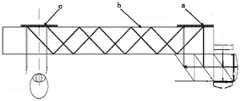
目前适于批量复制生产的光栅波导结构为表面浮雕光栅与玻璃光波导的组合结构,Akonia,Dispelix,waveoptics,微软等公司和研究机构在开发此方案。传统方案的结构如图1所示,可成像AR镜片包括耦入光栅a、耦出光栅c及衬底光波导b三部分,耦出和耦入光栅的光栅周期常数一样。此光学显示方案的原理:窄带图像源光线经准直透镜后变成平行光到达耦入光栅a,由耦入光栅a的衍射效应使平行光改变传输方向,因衍射光束满足全反射条件,光线沿着光栅的衬底,即衬底光波导b传输,当平行光传输到耦出光栅c时,耦出光栅c对分散的光线重新组合,使其按照耦合输入的方向重新输出到衬底光波导b外。At present, the grating waveguide structure suitable for mass production is the combined structure of surface relief grating and glass optical waveguide. Akonia, Dispelix, waveoptics, Microsoft and other companies and research institutions are developing this scheme. The structure of the traditional solution is shown in Figure 1. The imageable AR lens includes three parts: coupled-in grating a, coupled-out grating c, and substrate optical waveguide b. The grating period constants of the coupled-out and coupled-in gratings are the same. The principle of this optical display scheme: the light of the narrow-band image source becomes parallel light after passing through the collimating lens and reaches the coupling grating a. The diffraction effect of the coupling grating a changes the transmission direction of the parallel light. Since the diffracted light beam satisfies the condition of total reflection, the light Along the substrate of the grating, that is, the substrate optical waveguide b, when the parallel light is transmitted to the coupling-out grating c, the coupling-out grating c recombines the scattered light, so that it is re-output to the substrate light according to the direction of coupling input. outside the waveguide b.
因光栅的窄带光学特性,光栅波导结构在全彩色显示和色彩还原度方面存在较大挑战,为了达到多色显示的目的,一般采用多个光栅波导结构叠加的方式。常见方案为两到三层光栅波导结构粘合叠加的方式。一般采用光学胶水或双面胶粘合。如微软的HoloLens,Magic leap one等设备。Due to the narrow-band optical properties of gratings, the grating waveguide structure has great challenges in full-color display and color reproduction. In order to achieve multi-color display, a method of stacking multiple grating waveguide structures is generally used. A common solution is the way of bonding and stacking two to three-layer grating waveguide structures. Generally, optical glue or double-sided tape is used for bonding. Such as Microsoft's HoloLens, Magic leap one and other devices.
作为可穿戴设备的元件,对普通消费者,通常要求AR镜片具有视场角大,结构紧凑,美观的特点。作为信息显示元件,观察视场范围的大小直接影响到观察者获取信息的完整性甚至人员的安全。常见的光栅波导平板结构由于受限于波导材料折射率,这种结构的AR镜片视场角有待提高。另外由于是平板结构,图像平面上各像素点与人眼距离不等,显示效果的保真度和沉浸感较差。As a component of wearable devices, for ordinary consumers, AR lenses are usually required to have a large field of view, compact structure and beautiful appearance. As an information display element, the size of the observation field of view directly affects the integrity of the information obtained by the observer and even the safety of the personnel. The common grating waveguide plate structure is limited by the refractive index of the waveguide material, and the field angle of the AR lens of this structure needs to be improved. In addition, due to the flat structure, the distance between each pixel on the image plane and the human eye is not equal, and the fidelity and immersion of the display effect are poor.
因此,现有技术存在不足,需要改进。Therefore, the existing technology has shortcomings and needs to be improved.
发明内容SUMMARY OF THE INVENTION
本发明的目的是克服现有技术的不足,提供一种用于增强现实的光栅波导。The purpose of the present invention is to overcome the deficiencies of the prior art and provide a grating waveguide for augmented reality.
本发明的技术方案如下:提供一种用于增强现实的光栅波导,包括:显示光源、与所述显示光源相对设置的波导元件、以及位于所述波导元件上的耦合元件;所述耦合元件包括第一耦入光栅和第一耦出光栅,所述波导元件、所述第一耦入光栅和第一耦出光栅均为曲面结构且具有相同曲率。The technical solution of the present invention is as follows: a grating waveguide for augmented reality is provided, comprising: a display light source, a waveguide element arranged opposite to the display light source, and a coupling element located on the waveguide element; the coupling element includes The first coupling-in grating and the first coupling-out grating, the waveguide element, the first coupling-in grating and the first coupling-out grating are all curved structures and have the same curvature.
所述显示光源发出的光线经所述波导元件和所述第一耦入光栅作用后在所述波导元件中实现全反射,经所述第一耦出光栅和所述波导元件作用后入射到观察者的视野中。The light emitted by the display light source is fully reflected in the waveguide element after being acted by the waveguide element and the first coupling grating, and is incident to the observation after being acted by the first coupling out grating and the waveguide element. in the viewer's field of vision.
进一步地,所述波导元件、所述第一耦入光栅和第一耦出光栅的曲率中心均位于所述观察者这一侧。Further, the center of curvature of the waveguide element, the first coupling-in grating and the first coupling-out grating are all located on the side of the observer.
进一步地,所述第一耦入光栅和第一耦出光栅位于所述波导元件且远离所述观察者一侧的表面上;或,所述第一耦入光栅和第一耦出光栅位于所述波导元件且靠近所述观察者一侧的表面上。Further, the first in-coupling grating and the first out-coupling grating are located on the surface of the waveguide element on the side away from the observer; or, the first in-coupling grating and the first out-coupling grating are located on the on the surface of the waveguide element on the side close to the observer.
进一步地,所述耦合元件还包括:第二耦入光栅和第二耦出光栅;所述第二耦入光栅和第二耦出光栅位于所述波导元件,且与所述第一耦入光栅和第一耦出光栅在所述波导元件不同侧的表面上;所述第二耦入光栅和第二耦出光栅均与所述波导元件具有相同的曲率。Further, the coupling element further includes: a second coupling-in grating and a second coupling-out grating; the second coupling-in grating and the second coupling-out grating are located on the waveguide element and are connected to the first coupling-in grating and the first out-coupling grating on surfaces on different sides of the waveguide element; both the second in-coupling grating and the second out-coupling grating have the same curvature as the waveguide element.
所述显示光源发出的光线经所述第二耦入光栅、所述波导元件以及所述第一耦入光栅作用后,在所述波导元件中实现全反射,最后经所述第一耦出光栅、所述波导元件和所述第二耦出光栅作用后入射到观察者的视野中。After the light emitted by the display light source is acted by the second coupling grating, the waveguide element and the first coupling grating, total reflection is realized in the waveguide element, and finally the first coupling grating is passed out. , the waveguide element and the second outcoupling grating are incident into the field of view of the observer after the action.
进一步地,所述光栅波导还包括:设置于所述显示光源与所述波导元件之间的准直透镜;所述显示光源发出的光线经所述准直透镜准直后进入所述波导元件。Further, the grating waveguide further comprises: a collimating lens disposed between the display light source and the waveguide element; the light emitted by the display light source enters the waveguide element after being collimated by the collimating lens.
进一步地,所述光栅波导还包括:用于矫正屈光度的负透镜;所述负透镜设置于所述波导元件上且靠近所述观察者一侧;从所述波导元件出射的光线最终经所述负透镜后入射至所述观察者的视野中。Further, the grating waveguide further comprises: a negative lens for correcting the diopter; the negative lens is arranged on the waveguide element and is close to the side of the observer; the light emitted from the waveguide element finally passes through the The negative lens is incident on the observer's field of view.
进一步地,所述耦合元件为体相位光栅或表面浮雕光栅,且所述耦合元件与所述波导元件为一体结构。Further, the coupling element is a volume phase grating or a surface relief grating, and the coupling element and the waveguide element have an integral structure.
进一步地,所述体相位光栅直接制备于所述波导元件的表面;或,先在聚合物薄膜上制备出所述体相位光栅,再将所述聚合物薄膜复制或贴合在所述波导元件的表面。Further, the volume phase grating is directly prepared on the surface of the waveguide element; or, the volume phase grating is prepared on a polymer film first, and then the polymer film is copied or attached to the waveguide element s surface.
所述表面浮雕光栅采用微纳制造技术直接制备于所述波导元件的表面;或,先将所述表面浮雕光栅制备于聚合物薄膜上,再将具有所述表面浮雕光栅的聚合物薄膜复制或贴合到所述波导元件的表面。The surface relief grating is directly prepared on the surface of the waveguide element by using a micro-nano fabrication technology; or, the surface relief grating is first prepared on a polymer film, and then the polymer film with the surface relief grating is copied or Attached to the surface of the waveguide element.
进一步地,所述耦合元件包括三片层叠设置的所述体相位光栅或所述表面浮雕光栅,每片所述体相位光栅或所述表面浮雕光栅对应一种颜色的波长,进而实现RGB全彩显示。Further, the coupling element includes three pieces of the volume phase grating or the surface relief grating arranged in layers, and each piece of the volume phase grating or the surface relief grating corresponds to a wavelength of one color, thereby realizing RGB full color. show.
或,所述耦合元件采用角度复用的方式制备单片所述体相位光栅或所述表面浮雕光栅,进而实现单片光栅RGB三色传输。Or, the coupling element uses an angle multiplexing method to prepare the monolithic volume phase grating or the surface relief grating, so as to realize RGB three-color transmission of the monolithic grating.
进一步地,所述波导元件的表面设有镀膜层,所述镀膜层用于对所述波导元件的全反射进行扩展。Further, a coating layer is provided on the surface of the waveguide element, and the coating layer is used to extend the total reflection of the waveguide element.
采用上述方案,本发明的有益效果如下:Adopt the above scheme, the beneficial effects of the present invention are as follows:
1、在光栅元件长度相同的情况的,与传统结构相比,本发明曲面结构的光栅的视野大;作为AR眼镜镜片组件,在曲率设计合适时,图像面上每一点到达眼睛的距离相等,无论是像面中央区域还是边缘区域,佩戴者即使从屏幕边缘处也可以获得最佳观看效果,图像边缘显示效果更好,视角更为宽广,增强现场感和内容沉浸感。1. When the length of the grating element is the same, compared with the traditional structure, the grating of the curved structure of the present invention has a larger field of view; as an AR glasses lens component, when the curvature design is appropriate, the distance from each point on the image surface to the eye is equal, Whether it is the central area or the edge area of the image surface, the wearer can get the best viewing effect even from the edge of the screen, the image edge display effect is better, the viewing angle is wider, and the sense of presence and content immersion is enhanced.
2、曲面的波导元件更易与屈光镜片适配,只需在曲面的波导元件上贴合一片负透镜,即可实现屈光度调节的目的,同时能够使整个光学系统的体积减小、重量减轻,成本更低,屈光度矫正简单易行,解决了屈光度异常人眼观察带来的不便。2. The curved waveguide element is easier to adapt to the dioptric lens. Only a negative lens is attached to the curved waveguide element to achieve the purpose of diopter adjustment, and at the same time, the volume and weight of the entire optical system can be reduced. The cost is lower, the diopter correction is simple and easy, and the inconvenience caused by human eye observation with abnormal diopter is solved.
附图说明Description of drawings
图1位现有技术中平面光栅波导的结构示意图;Figure 1 is a schematic structural diagram of a planar grating waveguide in the prior art;
图2为本发明光栅波导一实施例的结构示意图;FIG. 2 is a schematic structural diagram of an embodiment of the grating waveguide of the present invention;
图3为本发明的光栅波导与传统平面光栅波导视角对比图;FIG. 3 is a view comparing the grating waveguide of the present invention and the conventional plane grating waveguide;
图4为本发明光栅波导另一实施例的结构示意图;FIG. 4 is a schematic structural diagram of another embodiment of the grating waveguide of the present invention;
图5为本发明光栅波导又一实施例的结构示意图;FIG. 5 is a schematic structural diagram of another embodiment of the grating waveguide of the present invention;
图6位本发明光栅波导中耦合元件一实施例的结构示意图。FIG. 6 is a schematic structural diagram of an embodiment of the coupling element in the grating waveguide of the present invention.
具体实施方式Detailed ways
以下结合附图和具体实施例,对本发明进行详细说明。The present invention will be described in detail below with reference to the accompanying drawings and specific embodiments.
本发明实施例提供的用于增强现实的光栅波导,包括:显示光源、与显示光源相对设置的波导元件、以及位于波导元件上的耦合元件;该耦合元件包括第一耦入光栅和第一耦出光栅。其中,该波导元件、第一耦入光栅和第一耦出光栅均为曲面结构且具有相同的曲率。耦合元件与波导元件可以为一体结构,也可以是耦合元件紧密贴合在波导元件的表面上。The grating waveguide for augmented reality provided by the embodiment of the present invention includes: a display light source, a waveguide element disposed opposite to the display light source, and a coupling element located on the waveguide element; the coupling element includes a first coupling grating and a first coupling element out grating. Wherein, the waveguide element, the first coupling-in grating and the first coupling-out grating are all curved structures and have the same curvature. The coupling element and the waveguide element may be an integral structure, or the coupling element may be closely attached to the surface of the waveguide element.
本发明实施例的光栅波导工作时,显示光源发出的光线经波导元件和第一耦入光栅共同作用后在波导元件中实现全反射,经第一耦出光栅和波导元件共同作用后入射到观察者的视野中。由于第一耦入光栅、第一耦出光栅和波导元件均为曲面结构且具有相同的曲率,因此相比传统的平面波导光栅具有更大的视野。并且在曲率设计合适时,图像面上每一点到达眼睛的距离相等,无论是像面中央区域还是边缘区域,佩戴者即使从屏幕边缘处也可以获得最佳观看效果,图像边缘显示效果更好,视角更为宽广,增强现场感和内容沉浸感。When the grating waveguide of the embodiment of the present invention is in operation, the light emitted by the display light source is fully reflected in the waveguide element after the waveguide element and the first coupling grating act together, and then enters the observation after the first coupling out grating and the waveguide element act together. in the viewer's field of vision. Since the first coupling-in grating, the first coupling-out grating and the waveguide element are all curved structures and have the same curvature, they have a larger field of view than the conventional planar waveguide grating. And when the curvature design is appropriate, the distance from each point on the image surface to the eye is equal, whether it is the central area or the edge area of the image surface, the wearer can get the best viewing effect even from the edge of the screen, and the image edge display effect is better, The viewing angle is wider, enhancing the sense of presence and content immersion.
可以理解的是,本发明实施例的光栅波导,其第一耦入光栅和第一耦出光栅可以位于波导元件远离观察者一侧的表面上,也可以位于靠近观察者一侧的表面上。It can be understood that, in the grating waveguide of the embodiment of the present invention, the first coupling grating and the first coupling grating can be located on the surface of the waveguide element on the side away from the observer, or on the surface on the side close to the observer.
当第一耦入光栅和第一耦出光栅位于远离观察者一侧的表面上时,本发明实施例的光栅波导的工作过程可以是:来自显示光源的光线进入波导元件后入射至第一耦入光栅,经第一耦入光栅反射后在波导元件中实现全反射,并传输至第一耦出光栅,经第一耦出光栅反射后的光线通过波导元件后进入观察者的视野中。When the first in-coupling grating and the first out-coupling grating are located on the surface away from the observer, the working process of the grating waveguide according to the embodiment of the present invention may be as follows: the light from the display light source enters the waveguide element and then enters the first coupling grating. The input grating realizes total reflection in the waveguide element after being reflected by the first coupling grating, and transmits to the first output coupling grating. The light reflected by the first coupling grating passes through the waveguide element and enters the observer's field of vision.
当第一耦入光栅和第一耦出光栅位于靠近观察者一侧的表面上时,本发明实施例的光栅波导的工作过程可以是:来自显示光源的光线第一耦入光栅透射后进入波导元件,在波导元件中实现全反射并传输至第一耦出光栅。经第一耦出光栅透射后的光线进入观察者的视野中。When the first in-coupling grating and the first out-coupling grating are located on the surface close to the observer, the working process of the grating waveguide according to the embodiment of the present invention may be as follows: the light from the display light source is transmitted through the first in-coupling grating and then enters the waveguide element, achieving total reflection in the waveguide element and transmission to the first outcoupling grating. The light transmitted through the first coupling-out grating enters the field of view of the observer.
另外需要说明的是,本发明实施例的光栅波导,波导元件、第一耦入光栅和第一耦出光栅的曲率中心均位于所述观察者这一侧。并且,光栅波导除包括上述部件外,还可以包括:准直透镜。进一步优化的方案,光栅波导还可以包括可以用于进行屈光度调节的负透镜。下面,将以第一耦入光栅和第一耦出光栅位于远离观察者一侧的表面上为例,结合具体实施例进行详细说明。In addition, it should be noted that, in the grating waveguide according to the embodiment of the present invention, the curvature centers of the waveguide element, the first coupling grating and the first coupling grating are all located on the side of the observer. Moreover, in addition to the above components, the grating waveguide may also include: a collimating lens. In a further optimized solution, the grating waveguide may also include a negative lens that can be used for diopter adjustment. In the following, the first coupling-in grating and the first out-coupling grating are located on a surface away from the observer as an example, and will be described in detail in conjunction with specific embodiments.
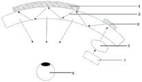
请参阅图2至图4,本发明提供一种用于增强现实的光栅波导,包括:显示光源1、与显示光源1相对设置的波导元件2、设于显示光源1与波导元件2之间的准直透镜5、设于波导元件2上的耦合元件、设于波导元件2靠近观察者6这一侧的负透镜7。波导元件2为曲面结构。耦合元件包括第一耦入光栅3和第一耦出光栅4。第一耦入光栅3和第一耦出光栅4也为曲面结构且与波导元件2具有相同的曲率,第一耦入光栅3和第一耦出光栅4位于波导元件2上远离观察者一侧的表面上,三者的曲率中心均位于靠近观察者6这一侧。准直透镜5用于对显示光源1出射的光线进行准直。负透镜7与曲面结构的波导元件2适配,负透镜7通过光学胶层8贴合在波导元件2上,用于矫正屈光度。Referring to FIGS. 2 to 4 , the present invention provides a grating waveguide for augmented reality, comprising: a display
请参阅图2至图4,曲面的光栅波导的原理为:主要采用光栅衍射、全反射以及负透镜屈光度矫正原理实现的。Please refer to FIG. 2 to FIG. 4. The principle of the curved grating waveguide is: it is mainly realized by the principles of grating diffraction, total reflection and negative lens diopter correction.
具体地,来自显示光源1的光线经像差矫正良好的准直透镜5准直以后经波导元件2后入射至第一耦入光栅3,经第一耦入光栅3反射后在波导元件2中全反射至第一耦出光栅4,最后经第一耦出光栅4反射后通过波导元件2入射到负透镜7,经负透镜7进入观察者6的视野中。由于第一耦出光栅4的存在,打破了光线在波导元件2中的全反射传播条件,使得光线可以从波导元件2射出。而对于来自周围景物的光线,经过波导元件2上下表面的透射直接进入到人眼,从而完成图像信息和周围景物信息的实时观察。Specifically, the light from the display
本发明实施例的曲面结构的光栅波导,由于耦合元件与波导元件2均为曲面结构,与传统的平面结构的波导光栅相比,扩大了光栅波导的视角,达到扩大光波导可视区域的目的,增强临场感,可以提升观察者的观看体验。如图3所示,本实施例中曲面结构的光栅波导器件的尺寸为:长度为5.5cm,曲率半径为8-20cm,出瞳距离为3-8cm,针对同样长度的平面光栅波导器件,曲面结构较平面结构有较大的视场角。并且,在曲率设计合适时,图像面上每一点到达眼睛的距离相等,无论是像面中央区域还是边缘区域,佩戴者即使从屏幕边缘处也可以获得最佳观看效果,图像边缘显示效果更好,视角更为宽广,增强现场感和内容沉浸感。The grating waveguide of the curved structure of the embodiment of the present invention, because the coupling element and the
进一步地,本发明实施例的曲面结构的光栅波导,由于波导元件2为曲面结构,因此只需在曲面的波导元件2上靠近观察者这一侧贴合一片负透镜7,通过波导元件2与负透镜7的相互配合,即可实现屈光度调节的目的,同时还能够使整个光学系统的体积减小、重量减轻,成本更低,屈光度矫正简单易行,解决了屈光度异常人眼观察带来的不便。Further, in the grating waveguide of the curved surface structure of the embodiment of the present invention, since the
请参阅图2至图5,具体地,本实施例中,波导元件2的内表面和/或外表面具有自由曲面结构,如球面或复曲面或任何其他规则几何形状的曲面结构。波导元件2的材料可用无机玻璃材料(如JGS1、JGS2、BK7等),或有机热塑性塑料(如聚碳酸酯、聚甲基丙烯酸甲酯),或透明的热固性材料(如基于丙烯酸酯、聚氨酯、聚脲、聚硫胺甲酸酯和烯丙基二甘醇碳酸酯等有机玻璃)。由于波导材料本身的限制,依赖于空气-玻璃界面之间的全内反射的平板波导可具有从全内反射角度到90°(在此范围内反射仍然存在,并且其角度是从法线到表面测量的)的反射。在曲面的波导元件2传输中允许FOV(field of view--视角)超过全反射角可允许的范围。为进一步扩大传输图像的范围,通常在波导元件2的表面镀一层具有一定折射率的镀膜层,对波导元件2的全反射给予一定的扩展。Please refer to FIGS. 2 to 5 . Specifically, in this embodiment, the inner surface and/or the outer surface of the
可以理解的是,本发明实施例的耦合元件,除包括第一耦入光栅和第一耦出光栅以外,还可以包括:第二耦入光栅和第二耦出光栅,且第二耦入光栅和第二耦出光栅均与波导元件具有相同的曲率。第二耦入光栅和第二耦出光栅位于波导元件上,且与第一耦入光栅和第一耦出光栅在波导元件不同侧的表面上。即是说,当第一耦入光栅和第一耦出光栅在波导元件上且远离观察者一侧的表面上时,第二耦入光栅和第二耦出光栅则位于波导元件上且靠近观察者一侧的表面上。当第一耦入光栅和第一耦出光栅在波导元件上且靠近观察者一侧的表面上时,第二耦入光栅和第二耦出光栅则位于波导元件上且远离观察者一侧的表面上。It can be understood that, in addition to the first coupling-in grating and the first coupling-out grating, the coupling element in the embodiment of the present invention may further include: a second coupling-in grating and a second coupling-out grating, and the second coupling-in grating and the second outcoupling grating have the same curvature as the waveguide element. The second in-coupling grating and the second out-coupling grating are located on the waveguide element and on surfaces on different sides of the waveguide element than the first in-coupling grating and the first out-coupling grating. That is, when the first in-coupling grating and the first out-coupling grating are on the waveguide element and on the surface on the side facing away from the viewer, the second in-coupling grating and the second out-coupling grating are on the waveguide element and close to the observation on the surface on the user's side. When the first in-coupling grating and the first out-coupling grating are on the surface of the waveguide element on the side close to the observer, the second in-coupling grating and the second out-coupling grating are located on the waveguide element and on the side away from the observer. on the surface.
下面,将结合具体实施例进行详细说明。In the following, detailed description will be given in conjunction with specific embodiments.
请再次参阅图2至图5,本发明另一实施例中,第一耦入光栅3和第一耦出光栅4位于波导元件2远离显示光源1这一侧的表面,第二耦入光栅9和第二耦出光栅10则位于波导元件2靠近显示光源1这一侧的表面。增加第二耦入光栅9和第二耦出光栅10,能够增强耦出耦入光效率和显示均匀性,提升显示效果。Please refer to FIG. 2 to FIG. 5 again. In another embodiment of the present invention, the first coupling grating 3 and the first coupling grating 4 are located on the surface of the
此时,光栅波导的工作原理是:显示光源1发出的光线经准直透镜5、第二耦入光栅9后进入波导元件2,并入射至第一耦入光栅3,经第一耦入光栅3反射后在波导元件2中全反射至第一耦出光栅4,最后经第一耦出光栅4反射后通过波导元件2、第二耦出光栅10后,最后经负透镜7入射到观察者6的视野中。At this time, the working principle of the grating waveguide is: the light emitted by the display
需要说明的是,耦合元件2可以是体相位光栅,也可以是表面浮雕光栅。本发明实施例波导元件2与耦合元件优选为一体成型结构,所述一体成型结构可以通过以下两种方式实现:It should be noted that the
针对体相位光栅,一种是将体相位光栅直接制备于曲面的波导元件2上,首先将感光材料(如银盐材料、重铬酸盐明胶、光致聚合物等)涂布于曲面的所述波导元件2表面,用全息摄影方法曝光并记录球面光波和平面光波的相干条纹,制备出表面具有体相位光栅的曲面波导;另一种方式,首先在涂布有感光材料的柔性的平面聚合物薄膜(如PET等高分子聚合物薄膜)上制备体相位光栅,再将上述制备有体相位光栅的平面聚合物薄膜曝光复制或贴合到曲面的波导元件2的表面,此种方式适用于批量化生产。For the volume phase grating, one is to directly prepare the volume phase grating on the
针对表面浮雕光栅,一种方式是采用微纳加工技术(如光刻、纳米压印、离子束刻蚀)直接将表面浮雕光栅制备在曲面的波导元件2上;另一种方式是,先将表面浮雕光栅制备在柔性的平面聚合物薄膜上(PET等高分子聚合物薄膜),在将上述制备好表面浮雕光栅的平面聚合物薄膜复制或贴合到曲面的波导元件表面,这种方式适用于批量化生产。For the surface relief grating, one way is to directly prepare the surface relief grating on the
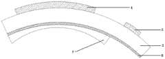
进一步地,为实现RGB全彩显示,本实施例的光栅波导中,如图6所示,耦合元件可以包括三片体相位光栅或表面浮雕光栅叠加而成,每片体相位光栅或表面浮雕光栅对应一种颜色的波长,进而实现RGB三色,实现全彩显示。当然,耦合元件可以采用角度复用的方式制备单片体相位光栅或所述表面浮雕光栅,进而实现单片光栅RGB三色传输。Further, in order to realize RGB full-color display, in the grating waveguide of this embodiment, as shown in FIG. 6 , the coupling element may include three pieces of volume phase grating or surface relief grating superimposed, and each piece of volume phase grating or surface relief grating is superimposed. Corresponding to the wavelength of a color, and then realize RGB three colors, to achieve full-color display. Of course, the coupling element can use angle multiplexing to prepare a monolithic volume phase grating or the surface relief grating, so as to realize the RGB three-color transmission of the monolithic grating.
需要说明的是,本发明实施例的光栅波导,不仅可以应用于增强现实眼镜场景,也可以应用于抬头显示场景。It should be noted that, the grating waveguide of the embodiment of the present invention can be applied not only to the augmented reality glasses scene, but also to the head-up display scene.
综上所述,本发明的有益效果如下:To sum up, the beneficial effects of the present invention are as follows:
1、在光栅元件长度相同的情况的,与传统结构相比,本发明曲面光栅波导的视野更大;作为AR眼镜镜片组件,在曲率设计合适时,图像面上每一点到达眼睛的距离相等,无论是像面中央区域还是边缘区域,佩戴者即使从屏幕边缘处也可以获得最佳观看效果,图像边缘显示效果更好,视角更为宽广,增强现场感和内容沉浸感。1. When the length of the grating element is the same, compared with the traditional structure, the curved grating waveguide of the present invention has a larger field of view; as an AR glasses lens component, when the curvature design is appropriate, the distance from each point on the image surface to the eye is equal, Whether it is the central area or the edge area of the image surface, the wearer can get the best viewing effect even from the edge of the screen, the image edge display effect is better, the viewing angle is wider, and the sense of presence and content immersion is enhanced.
2、曲面波导元件更易与屈光镜片适配,只需在曲面波导元件上贴合一片负透镜,即可实现屈光度调节的目的,同时能够使整个光学系统的体积减小、重量减轻,成本更低,屈光度矫正简单易行,解决了屈光度异常人眼观察带来的不便。2. The curved waveguide element is easier to adapt to the dioptric lens. Only a negative lens is attached to the curved waveguide element to achieve the purpose of diopter adjustment, and at the same time, the volume, weight and cost of the entire optical system can be reduced. Low, the diopter correction is simple and easy, which solves the inconvenience caused by human eye observation with abnormal diopter.
以上仅为本发明的较佳实施例而已,并不用于限制本发明,凡在本发明的精神和原则之内所作的任何修改、等同替换和改进等,均应包含在本发明的保护范围之内。The above are only preferred embodiments of the present invention and are not intended to limit the present invention. Any modifications, equivalent replacements and improvements made within the spirit and principles of the present invention shall be included in the protection scope of the present invention. Inside.
Claims (10)
Priority Applications (2)
| Application Number | Priority Date | Filing Date | Title |
|---|---|---|---|
| CN201911139565.7ACN110806645A (en) | 2019-11-20 | 2019-11-20 | A grating waveguide for augmented reality |
| PCT/CN2020/117509WO2021098374A1 (en) | 2019-11-20 | 2020-09-24 | Grating waveguide for augmented reality |
Applications Claiming Priority (1)
| Application Number | Priority Date | Filing Date | Title |
|---|---|---|---|
| CN201911139565.7ACN110806645A (en) | 2019-11-20 | 2019-11-20 | A grating waveguide for augmented reality |
Publications (1)
| Publication Number | Publication Date |
|---|---|
| CN110806645Atrue CN110806645A (en) | 2020-02-18 |
Family
ID=69490636
Family Applications (1)
| Application Number | Title | Priority Date | Filing Date |
|---|---|---|---|
| CN201911139565.7APendingCN110806645A (en) | 2019-11-20 | 2019-11-20 | A grating waveguide for augmented reality |
Country Status (2)
| Country | Link |
|---|---|
| CN (1) | CN110806645A (en) |
| WO (1) | WO2021098374A1 (en) |
Cited By (14)
| Publication number | Priority date | Publication date | Assignee | Title |
|---|---|---|---|---|
| CN111308717A (en)* | 2020-03-31 | 2020-06-19 | 京东方科技集团股份有限公司 | Display module, display method, and display device |
| CN111458880A (en)* | 2020-05-09 | 2020-07-28 | 三生万物(北京)人工智能技术有限公司 | Waveguide light field display device and head-mounted augmented reality glasses |
| CN111812847A (en)* | 2020-08-20 | 2020-10-23 | 杭州光粒科技有限公司 | A waveguide device and AR display device |
| CN111830715A (en)* | 2020-07-28 | 2020-10-27 | 谷东科技有限公司 | Waveguide display device with two-dimensional extended pupil and augmented reality display equipment |
| CN111965826A (en)* | 2020-08-27 | 2020-11-20 | Oppo广东移动通信有限公司 | Control method and device of intelligent glasses, storage medium and intelligent glasses |
| CN112711142A (en)* | 2020-05-05 | 2021-04-27 | 谷东科技有限公司 | Volume holographic optical waveguide display device and augmented reality display apparatus |
| WO2021098374A1 (en)* | 2019-11-20 | 2021-05-27 | 深圳惠牛科技有限公司 | Grating waveguide for augmented reality |
| WO2021255332A1 (en)* | 2020-06-17 | 2021-12-23 | Dispelix Oy | Manufacturing method of optical element, optical element and apparatus for manufacturing optical element |
| CN114167606A (en)* | 2020-09-11 | 2022-03-11 | 宁波舜宇光电信息有限公司 | Optical waveguide assembly and display device including the same |
| CN114252997A (en)* | 2021-11-03 | 2022-03-29 | 上海大学 | Color near-to-eye display device and method based on cylindrical waveguide |
| CN114527533A (en)* | 2022-02-22 | 2022-05-24 | 珠海莫界科技有限公司 | Light optical waveguide for changing virtual image distance and head-mounted display |
| CN118511108A (en)* | 2022-01-20 | 2024-08-16 | 真利光学有限公司 | Eyeglass lenses with waveguides |
| RU2825552C1 (en)* | 2024-02-14 | 2024-08-27 | Самсунг Электроникс Ко., Лтд. | Optical combiner based on waveguide for displaying augmented reality, method of operating said optical combiner, augmented reality glasses based on said optical combiner |
| CN119247633A (en)* | 2024-11-29 | 2025-01-03 | 南京国兆光电科技有限公司 | A precision augmented reality optical module structure and assembly method |
Families Citing this family (2)
| Publication number | Priority date | Publication date | Assignee | Title |
|---|---|---|---|---|
| FI20216158A1 (en)* | 2021-11-11 | 2023-05-12 | Dispelix Oy | Waveguide, display device, method and apparatus |
| US12429701B2 (en) | 2021-12-13 | 2025-09-30 | Samsung Electronics Co., Ltd. | Augmented reality device based on curved waveguide, method therefor, augmented reality glasses based on said device |
Citations (11)
| Publication number | Priority date | Publication date | Assignee | Title |
|---|---|---|---|---|
| EP2246728A1 (en)* | 2009-04-29 | 2010-11-03 | BAE Systems PLC | Head mounted display |
| CN104520751A (en)* | 2012-08-02 | 2015-04-15 | 卡尔蔡司股份公司 | Display device |
| CN105700143A (en)* | 2016-03-01 | 2016-06-22 | 陈超平 | Optical display device facing augment reality |
| CN107167920A (en)* | 2017-06-19 | 2017-09-15 | 东南大学 | A kind of high brightness holographical wave guide display device |
| CN107533228A (en)* | 2015-07-06 | 2018-01-02 | 谷歌有限责任公司 | Added prescription corrections to eyepieces for see-through HMDs |
| CN107966819A (en)* | 2017-12-27 | 2018-04-27 | 北京灵犀微光科技有限公司 | Waveguide display device |
| CN109239920A (en)* | 2017-07-11 | 2019-01-18 | 苏州苏大维格光电科技股份有限公司 | A kind of holographical wave guide eyeglass and augmented reality display device |
| CN109407326A (en)* | 2018-12-31 | 2019-03-01 | 上海鲲游光电科技有限公司 | A kind of augmented reality display system and its manufacturing method based on diffraction integrator |
| CN109870808A (en)* | 2017-12-01 | 2019-06-11 | 苏州苏大维格光电科技股份有限公司 | A near-eye display lens and a near-eye display device |
| CN110471185A (en)* | 2019-08-28 | 2019-11-19 | 瑞声通讯科技(常州)有限公司 | Waveguide augmented reality display device |
| CN210639353U (en)* | 2019-11-20 | 2020-05-29 | 深圳惠牛科技有限公司 | Grating waveguide for augmented reality |
Family Cites Families (8)
| Publication number | Priority date | Publication date | Assignee | Title |
|---|---|---|---|---|
| ATE552524T1 (en)* | 2004-12-13 | 2012-04-15 | Nokia Corp | SYSTEM AND METHOD FOR EXPANSION OF NEAR FOCUS RADIANT IN A DISPLAY DEVICE |
| DE102008049407A1 (en)* | 2008-09-29 | 2010-04-01 | Carl Zeiss Ag | Display device and display method |
| DE102013219624B3 (en)* | 2013-09-27 | 2015-01-22 | Carl Zeiss Ag | Spectacle lens for a display device which can be placed on the head of a user and generates an image, and a display device with such a spectacle lens |
| CN104116495B (en)* | 2014-07-11 | 2016-02-10 | 北京理工大学 | A kind of Technology of Retina Optical Coherence Tomography detection-display system |
| CN108828780A (en)* | 2018-08-29 | 2018-11-16 | 深圳珑璟光电技术有限公司 | A kind of nearly eye display Optical devices based on holographic grating |
| CN111175971A (en)* | 2019-10-30 | 2020-05-19 | 北京理工大学 | A near-eye optical display system, augmented reality glasses |
| CN110806645A (en)* | 2019-11-20 | 2020-02-18 | 深圳惠牛科技有限公司 | A grating waveguide for augmented reality |
| CN111458880B (en)* | 2020-05-09 | 2022-04-22 | 三生万物(北京)人工智能技术有限公司 | Waveguide light field display device and head-mounted augmented reality glasses |
- 2019
- 2019-11-20CNCN201911139565.7Apatent/CN110806645A/enactivePending
- 2020
- 2020-09-24WOPCT/CN2020/117509patent/WO2021098374A1/ennot_activeCeased
Patent Citations (11)
| Publication number | Priority date | Publication date | Assignee | Title |
|---|---|---|---|---|
| EP2246728A1 (en)* | 2009-04-29 | 2010-11-03 | BAE Systems PLC | Head mounted display |
| CN104520751A (en)* | 2012-08-02 | 2015-04-15 | 卡尔蔡司股份公司 | Display device |
| CN107533228A (en)* | 2015-07-06 | 2018-01-02 | 谷歌有限责任公司 | Added prescription corrections to eyepieces for see-through HMDs |
| CN105700143A (en)* | 2016-03-01 | 2016-06-22 | 陈超平 | Optical display device facing augment reality |
| CN107167920A (en)* | 2017-06-19 | 2017-09-15 | 东南大学 | A kind of high brightness holographical wave guide display device |
| CN109239920A (en)* | 2017-07-11 | 2019-01-18 | 苏州苏大维格光电科技股份有限公司 | A kind of holographical wave guide eyeglass and augmented reality display device |
| CN109870808A (en)* | 2017-12-01 | 2019-06-11 | 苏州苏大维格光电科技股份有限公司 | A near-eye display lens and a near-eye display device |
| CN107966819A (en)* | 2017-12-27 | 2018-04-27 | 北京灵犀微光科技有限公司 | Waveguide display device |
| CN109407326A (en)* | 2018-12-31 | 2019-03-01 | 上海鲲游光电科技有限公司 | A kind of augmented reality display system and its manufacturing method based on diffraction integrator |
| CN110471185A (en)* | 2019-08-28 | 2019-11-19 | 瑞声通讯科技(常州)有限公司 | Waveguide augmented reality display device |
| CN210639353U (en)* | 2019-11-20 | 2020-05-29 | 深圳惠牛科技有限公司 | Grating waveguide for augmented reality |
Cited By (19)
| Publication number | Priority date | Publication date | Assignee | Title |
|---|---|---|---|---|
| WO2021098374A1 (en)* | 2019-11-20 | 2021-05-27 | 深圳惠牛科技有限公司 | Grating waveguide for augmented reality |
| CN111308717A (en)* | 2020-03-31 | 2020-06-19 | 京东方科技集团股份有限公司 | Display module, display method, and display device |
| CN111308717B (en)* | 2020-03-31 | 2022-03-25 | 京东方科技集团股份有限公司 | Display module, display method and display device |
| CN112711142A (en)* | 2020-05-05 | 2021-04-27 | 谷东科技有限公司 | Volume holographic optical waveguide display device and augmented reality display apparatus |
| CN111458880A (en)* | 2020-05-09 | 2020-07-28 | 三生万物(北京)人工智能技术有限公司 | Waveguide light field display device and head-mounted augmented reality glasses |
| CN111458880B (en)* | 2020-05-09 | 2022-04-22 | 三生万物(北京)人工智能技术有限公司 | Waveguide light field display device and head-mounted augmented reality glasses |
| WO2021255332A1 (en)* | 2020-06-17 | 2021-12-23 | Dispelix Oy | Manufacturing method of optical element, optical element and apparatus for manufacturing optical element |
| EP4168834A4 (en)* | 2020-06-17 | 2024-07-24 | Dispelix Oy | Manufacturing method of optical element, optical element and apparatus for manufacturing optical element |
| CN111830715A (en)* | 2020-07-28 | 2020-10-27 | 谷东科技有限公司 | Waveguide display device with two-dimensional extended pupil and augmented reality display equipment |
| CN111812847A (en)* | 2020-08-20 | 2020-10-23 | 杭州光粒科技有限公司 | A waveguide device and AR display device |
| CN111965826B (en)* | 2020-08-27 | 2022-11-15 | Oppo广东移动通信有限公司 | Control method and device of intelligent glasses, storage medium and intelligent glasses |
| CN111965826A (en)* | 2020-08-27 | 2020-11-20 | Oppo广东移动通信有限公司 | Control method and device of intelligent glasses, storage medium and intelligent glasses |
| CN114167606A (en)* | 2020-09-11 | 2022-03-11 | 宁波舜宇光电信息有限公司 | Optical waveguide assembly and display device including the same |
| CN114167606B (en)* | 2020-09-11 | 2023-11-10 | 宁波舜宇光电信息有限公司 | Optical waveguide assembly and display apparatus including the same |
| CN114252997A (en)* | 2021-11-03 | 2022-03-29 | 上海大学 | Color near-to-eye display device and method based on cylindrical waveguide |
| CN118511108A (en)* | 2022-01-20 | 2024-08-16 | 真利光学有限公司 | Eyeglass lenses with waveguides |
| CN114527533A (en)* | 2022-02-22 | 2022-05-24 | 珠海莫界科技有限公司 | Light optical waveguide for changing virtual image distance and head-mounted display |
| RU2825552C1 (en)* | 2024-02-14 | 2024-08-27 | Самсунг Электроникс Ко., Лтд. | Optical combiner based on waveguide for displaying augmented reality, method of operating said optical combiner, augmented reality glasses based on said optical combiner |
| CN119247633A (en)* | 2024-11-29 | 2025-01-03 | 南京国兆光电科技有限公司 | A precision augmented reality optical module structure and assembly method |
Also Published As
| Publication number | Publication date |
|---|---|
| WO2021098374A1 (en) | 2021-05-27 |
Similar Documents
| Publication | Publication Date | Title |
|---|---|---|
| CN110806645A (en) | A grating waveguide for augmented reality | |
| US20210003849A1 (en) | Compact head-mounted display system protected by a hyperfine structure | |
| EP3458898B1 (en) | Head-mounted imaging device | |
| EP3796070A1 (en) | Augmented reality device and optical system thereof | |
| CN105829952B (en) | Transparent eyepiece for head wearable display | |
| WO2020056513A1 (en) | Optical combiner lens for wearable heads-up display | |
| CN103941398B (en) | See-Through Glasses Display | |
| CN211826725U (en) | Optical system of micro head-mounted display | |
| CN102213830A (en) | Head Mounted Display | |
| CN108732767A (en) | A kind of nearly eye of compact free form surface waveguide shows Optical devices | |
| CN108828780A (en) | A kind of nearly eye display Optical devices based on holographic grating | |
| WO2015007201A1 (en) | Wearable flat optical system | |
| CN210639353U (en) | Grating waveguide for augmented reality | |
| CN112213861A (en) | Light and thin type optical waveguide AR optical imaging system | |
| CN114660816A (en) | Optical device and AR apparatus | |
| KR20230050993A (en) | Waveguide and augmented reality device employing the same | |
| CN116661148A (en) | Optical waveguide device for VR display | |
| CN118938382A (en) | A diffractive optical structure, optical system and head-mounted display device | |
| CN113189704A (en) | Optical waveguide and near-to-eye display system | |
| CN208569195U (en) | A kind of nearly eye of compact free form surface waveguide shows Optical devices | |
| JP7441443B2 (en) | Optical systems and mixed reality devices | |
| CN110286490A (en) | Augmented reality optical system based on free-form surface and optical waveguide | |
| CN213690115U (en) | Light and thin type optical waveguide AR optical imaging system | |
| CN118671964A (en) | Device and method for manufacturing cholesteric liquid crystal device and near-eye display device | |
| CN210166569U (en) | Augmented reality optical system based on free-form surface and optical waveguide |
Legal Events
| Date | Code | Title | Description |
|---|---|---|---|
| PB01 | Publication | ||
| PB01 | Publication | ||
| SE01 | Entry into force of request for substantive examination | ||
| SE01 | Entry into force of request for substantive examination |