CN110801312A - Intervene valve release stop device - Google Patents
Intervene valve release stop deviceDownload PDFInfo
- Publication number
- CN110801312A CN110801312ACN201911000436.XACN201911000436ACN110801312ACN 110801312 ACN110801312 ACN 110801312ACN 201911000436 ACN201911000436 ACN 201911000436ACN 110801312 ACN110801312 ACN 110801312A
- Authority
- CN
- China
- Prior art keywords
- inflation
- valve
- airbag
- air bag
- limiting
- Prior art date
- Legal status (The legal status is an assumption and is not a legal conclusion. Google has not performed a legal analysis and makes no representation as to the accuracy of the status listed.)
- Pending
Links
Images


Classifications
- A—HUMAN NECESSITIES
- A61—MEDICAL OR VETERINARY SCIENCE; HYGIENE
- A61F—FILTERS IMPLANTABLE INTO BLOOD VESSELS; PROSTHESES; DEVICES PROVIDING PATENCY TO, OR PREVENTING COLLAPSING OF, TUBULAR STRUCTURES OF THE BODY, e.g. STENTS; ORTHOPAEDIC, NURSING OR CONTRACEPTIVE DEVICES; FOMENTATION; TREATMENT OR PROTECTION OF EYES OR EARS; BANDAGES, DRESSINGS OR ABSORBENT PADS; FIRST-AID KITS
- A61F2/00—Filters implantable into blood vessels; Prostheses, i.e. artificial substitutes or replacements for parts of the body; Appliances for connecting them with the body; Devices providing patency to, or preventing collapsing of, tubular structures of the body, e.g. stents
- A61F2/02—Prostheses implantable into the body
- A61F2/24—Heart valves ; Vascular valves, e.g. venous valves; Heart implants, e.g. passive devices for improving the function of the native valve or the heart muscle; Transmyocardial revascularisation [TMR] devices; Valves implantable in the body
- A61F2/2427—Devices for manipulating or deploying heart valves during implantation
- A61F2/243—Deployment by mechanical expansion
- A61F2/2433—Deployment by mechanical expansion using balloon catheter
Landscapes
- Health & Medical Sciences (AREA)
- Cardiology (AREA)
- Engineering & Computer Science (AREA)
- Biomedical Technology (AREA)
- Oral & Maxillofacial Surgery (AREA)
- Transplantation (AREA)
- Mechanical Engineering (AREA)
- Heart & Thoracic Surgery (AREA)
- Vascular Medicine (AREA)
- Life Sciences & Earth Sciences (AREA)
- Animal Behavior & Ethology (AREA)
- General Health & Medical Sciences (AREA)
- Public Health (AREA)
- Veterinary Medicine (AREA)
- Infusion, Injection, And Reservoir Apparatuses (AREA)
Abstract
Translated fromChineseDescription
Translated fromChinese技术领域technical field
本发明涉及医疗器械技术领域,特别涉及到一种介入瓣膜释放限位装置。The invention relates to the technical field of medical devices, in particular to a release limiting device for an interventional valve.
背景技术Background technique
在心脏介入手术不断发展的今天,越来越多的患者受益于该项技术的飞速发展所带来的效益,但目前仍有许多问题亟待解决。Today, with the continuous development of cardiac interventional surgery, more and more patients benefit from the benefits brought by the rapid development of this technology, but there are still many problems to be solved urgently.
在经导管的瓣膜置换术中,当术者将带有瓣膜的导管放置在合适位置时,需要对瓣膜内的气囊充气来保证瓣膜的顺利展开,然而目前市面上的气囊整体呈橄榄球形,即横截面为椭圆形(如图1所示),采用此种结构的气囊10在充气撑开瓣膜20时,会使瓣膜在气囊外侧发生或多或少的位移,即定位不准确,这将导致瓣膜释放位置发生偏移,严重影响了手术质量,给术者的瓣膜置换工作带来了较大的不便。In transcatheter valve replacement, when the operator places the catheter with the valve in the proper position, the balloon in the valve needs to be inflated to ensure the smooth deployment of the valve. The cross section is oval (as shown in Fig. 1), when the
发明内容SUMMARY OF THE INVENTION
为解决现有技术存在的问题,本发明目的提供了一种设计合理、结构简单,在膨胀气囊的两端分别设有限位气囊,有效地保证了介入瓣膜在释放过程中不会因为膨胀气囊的膨胀而导致瓣膜的移位,保证了介入瓣膜释放位置的准确性,极大地提高了瓣膜释放的成功率和手术质量的介入瓣膜释放限位装置。In order to solve the problems existing in the prior art, the purpose of the present invention is to provide a device with reasonable design and simple structure, wherein the two ends of the inflatable airbag are respectively provided with limit airbags, which effectively ensures that the interventional valve will not be affected by the inflated airbag during the release process. The displacement of the valve caused by the expansion ensures the accuracy of the release position of the interventional valve, and greatly improves the success rate of the valve release and the operation quality of the interventional valve release limiting device.
为解决以上技术问题,本发明采用以下技术方案来实现的:In order to solve the above technical problems, the present invention adopts the following technical solutions to realize:
一种介入瓣膜释放限位装置,包括An interventional valve release limiting device, comprising
一用于扩张瓣膜的膨胀气囊,在所述膨胀气囊上开设有第一充气口;an inflation balloon for expanding the valve, and a first inflation port is opened on the inflation balloon;
一用于为膨胀气囊进行充放气的第一充气系统,所述第一充气系统通过第一管路与膨胀气囊的第一充气口相连通;a first inflation system for inflating and deflating the inflation airbag, the first inflation system is communicated with the first inflation port of the inflation airbag through a first pipeline;
其特征在于,该介入瓣膜释放限位装置还包括一对称设置在膨胀气囊两端且用于限制瓣膜张开的位置的限位气囊,在所述限位气囊上开设有第二充气口,所述限位气囊的第二充气口通过第二管路与用于为其进行充放气的第二充气系统相连通。It is characterized in that, the intervening valve release limiting device further includes a limiting airbag symmetrically arranged at both ends of the inflation airbag and used to limit the position of the valve opening, and a second inflation port is opened on the limiting airbag, so The second inflation port of the limiting airbag is communicated with a second inflation system for inflating and deflating the airbag through a second pipeline.
在本发明的一个优选实施例中,所述限位气囊与膨胀气囊采用一体成型结构一体成型。In a preferred embodiment of the present invention, the limiting airbag and the inflation airbag are integrally formed using an integral molding structure.
在本发明的一个优选实施例中,所述膨胀气囊膨胀的最大外径与瓣膜张开的最大内径相同。In a preferred embodiment of the present invention, the expanded maximum outer diameter of the inflation balloon is the same as the maximum inner diameter of the valve opening.
与现有技术相比,本发明在膨胀气囊的两端分别设有一限位气囊,有效地保证了介入瓣膜在释放过程中不会因为膨胀气囊的膨胀而导致瓣膜的移位,保证了介入瓣膜释放位置的准确性,极大地提高了瓣膜释放的成功率和手术质量,给术者的瓣膜置换工作带来了较大的便利。Compared with the prior art, the present invention is provided with a limit air bag at both ends of the inflation air bag, which effectively ensures that the intervention valve will not be displaced due to the expansion of the inflation air bag during the release process, and ensures that the intervention valve is not displaced. The accuracy of the release position greatly improves the success rate of valve release and the quality of the operation, and brings great convenience to the operator's valve replacement work.
附图说明Description of drawings
为了更清楚地说明本发明实施例或现有技术中的技术方案,下面将对实施例或现有技术描述中所需要使用的附图作简单地介绍,显而易见地,下面描述中的附图仅仅是本发明的一些实施例,对于本领域普通技术人员来讲,在不付出创造性劳动的前提下,还可以根据这些附图获得其他的附图。In order to explain the embodiments of the present invention or the technical solutions in the prior art more clearly, the following briefly introduces the accompanying drawings that need to be used in the description of the embodiments or the prior art. Obviously, the accompanying drawings in the following description are only These are some embodiments of the present invention. For those of ordinary skill in the art, other drawings can also be obtained from these drawings without creative efforts.
图1为现有技术中气囊的结构示意图。FIG. 1 is a schematic structural diagram of an airbag in the prior art.
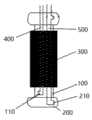
图2为本发明的结构示意图。FIG. 2 is a schematic structural diagram of the present invention.
图3为本发明限位气囊充气后的结构示意图。FIG. 3 is a schematic structural diagram of the limiting airbag of the present invention after inflation.
具体实施方式Detailed ways
为了使本发明实现的技术手段、创作特征、达成目的与功效易于明白了解,下面结合具体图示,进一步阐述本发明。In order to make the technical means, creation features, achievement goals and effects of the present invention easy to understand and understand, the present invention will be further described below with reference to the specific drawings.
参照图1-图3所示,图中给出了一种介入瓣膜释放限位装置,包括膨胀气囊100、第一充气系统和一对称设置在膨胀气囊100两端且用于限制瓣膜300张开的位置的限位气囊200。Referring to FIGS. 1-3 , an interventional valve release limiting device is shown in the figures, including an
膨胀气囊100用于扩张瓣膜300,在膨胀气囊100上开设有第一充气口110,第一充气系统用于为膨胀气囊100进行充放气,第一充气系统通过第一管路400与膨胀气囊100的第一充气口110相连通。The
上述膨胀气囊100可以在术中反复充气与放气,与瓣膜300只是表面相互接触,并不存在连接固定,当瓣膜300扩张处于合适位置时,可通过导管将气囊脱离瓣膜。The above-mentioned
在限位气囊200上开设有第二充气口210,限位气囊200的第二充气口210通过第二管路500与用于为其进行充放气的第二充气系统相连通,第一充气系统与第二充气系统为两个独立的充气系统,且分别对膨胀气囊100与限位气囊200进行充气,相互独立控制,互不干扰。A
限位气囊200与膨胀气囊100采用一体成型结构一体成型,采用此种结构有效的提高了限位气囊200与膨胀气囊100之间的稳定性能,避免限位气囊200相对膨胀气囊100发生移动。The
膨胀气囊100膨胀的最大外径与瓣膜300张开的最大内径相同,不同的瓣膜尺寸会有相应的膨胀气囊,保证其处于最佳合适状态,上述所有的材料完全能够适应医学器械的消毒要求。The maximum outer diameter of the
本发明的具体操作如下:The concrete operation of the present invention is as follows:
当术者将瓣膜300输送到所需要的位置时,此时通过第二充气系统对限位气囊200进行充气,保证瓣膜300不会移位,接着再通过第二充气系统对膨胀气囊100进行充气,使瓣膜300充分展开,术者可根据术中心超或X线引导下,反复充放气,保证瓣膜300处于合适的位置展开,最后再通过第一充气系统、第二充气系统将膨胀气囊100和限位气囊200中的气抽走,通过导管将气囊取走。When the operator delivers the
综上所述本发明在膨胀气囊的两端分别设有一限位气囊,有效地保证了介入瓣膜在释放过程中不会因为膨胀气囊的膨胀而导致瓣膜的移位,保证了介入瓣膜释放位置的准确性,极大地提高了瓣膜释放的成功率和手术质量,给术者的瓣膜置换工作带来了较大的便利。In summary, the present invention is provided with a limit airbag at both ends of the inflation airbag, which effectively ensures that the intervention valve will not be displaced due to the expansion of the inflation airbag during the release process, and ensures the release position of the interventional valve. The accuracy greatly improves the success rate of valve release and the operation quality, and brings great convenience to the operator's valve replacement work.
以上显示和描述了本发明的基本原理、主要特征和本发明的优点。本行业的技术人员应该了解,本发明不受上述实施例的限制,上述实施例和说明书中描述的只是说明本发明的原理,在不脱离本发明精神和范围的前提下本发明还会有各种变化和改进,这些变化和改进都落入要求保护的本发明范围内。本发明要求保护范围由所附的权利要求书及其等同物界定。The foregoing has shown and described the basic principles, main features and advantages of the present invention. It should be understood by those skilled in the art that the present invention is not limited by the above-mentioned embodiments. The above-mentioned embodiments and descriptions only illustrate the principle of the present invention. Such changes and improvements fall within the scope of the claimed invention. The claimed scope of the present invention is defined by the appended claims and their equivalents.
Claims (3)
Priority Applications (1)
| Application Number | Priority Date | Filing Date | Title |
|---|---|---|---|
| CN201911000436.XACN110801312A (en) | 2019-10-21 | 2019-10-21 | Intervene valve release stop device |
Applications Claiming Priority (1)
| Application Number | Priority Date | Filing Date | Title |
|---|---|---|---|
| CN201911000436.XACN110801312A (en) | 2019-10-21 | 2019-10-21 | Intervene valve release stop device |
Publications (1)
| Publication Number | Publication Date |
|---|---|
| CN110801312Atrue CN110801312A (en) | 2020-02-18 |
Family
ID=69488678
Family Applications (1)
| Application Number | Title | Priority Date | Filing Date |
|---|---|---|---|
| CN201911000436.XAPendingCN110801312A (en) | 2019-10-21 | 2019-10-21 | Intervene valve release stop device |
Country Status (1)
| Country | Link |
|---|---|
| CN (1) | CN110801312A (en) |
Citations (9)
| Publication number | Priority date | Publication date | Assignee | Title |
|---|---|---|---|---|
| US20060095066A1 (en)* | 2004-04-21 | 2006-05-04 | Exploramed Nc1, Inc. | Devices, systems and methods for treating disorders of the ear, nose and throat |
| CN101745173A (en)* | 2008-12-01 | 2010-06-23 | 胡大伟 | Medical valve plugging device |
| CN102366325A (en)* | 2011-10-21 | 2012-03-07 | 南昌大学第一附属医院 | Dysphagia pressure measurement and treatment instrument |
| CN202446642U (en)* | 2012-01-16 | 2012-09-26 | 张梅 | Novel stomach tube used in department of gastroenterology |
| CN102961199A (en)* | 2012-11-30 | 2013-03-13 | 宁波健世生物科技有限公司 | Anti-displacement pulmonary valve stent |
| CN103124533A (en)* | 2010-09-27 | 2013-05-29 | 金伯利-克拉克环球有限公司 | Multi-balloon dilation device for placing catheter tubes |
| CN108703823A (en)* | 2018-07-27 | 2018-10-26 | 武汉开阖同立医疗科技有限公司 | A kind of insertion type Puffer-type sacculus aortic valve stent system |
| CN108888387A (en)* | 2010-10-05 | 2018-11-27 | 爱德华兹生命科学公司 | Heart valve prosthesis |
| US20190298518A1 (en)* | 2011-02-11 | 2019-10-03 | Edwards Lifesciences Corporation | Stability device for use with percutaneous delivery systems |
- 2019
- 2019-10-21CNCN201911000436.XApatent/CN110801312A/enactivePending
Patent Citations (9)
| Publication number | Priority date | Publication date | Assignee | Title |
|---|---|---|---|---|
| US20060095066A1 (en)* | 2004-04-21 | 2006-05-04 | Exploramed Nc1, Inc. | Devices, systems and methods for treating disorders of the ear, nose and throat |
| CN101745173A (en)* | 2008-12-01 | 2010-06-23 | 胡大伟 | Medical valve plugging device |
| CN103124533A (en)* | 2010-09-27 | 2013-05-29 | 金伯利-克拉克环球有限公司 | Multi-balloon dilation device for placing catheter tubes |
| CN108888387A (en)* | 2010-10-05 | 2018-11-27 | 爱德华兹生命科学公司 | Heart valve prosthesis |
| US20190298518A1 (en)* | 2011-02-11 | 2019-10-03 | Edwards Lifesciences Corporation | Stability device for use with percutaneous delivery systems |
| CN102366325A (en)* | 2011-10-21 | 2012-03-07 | 南昌大学第一附属医院 | Dysphagia pressure measurement and treatment instrument |
| CN202446642U (en)* | 2012-01-16 | 2012-09-26 | 张梅 | Novel stomach tube used in department of gastroenterology |
| CN102961199A (en)* | 2012-11-30 | 2013-03-13 | 宁波健世生物科技有限公司 | Anti-displacement pulmonary valve stent |
| CN108703823A (en)* | 2018-07-27 | 2018-10-26 | 武汉开阖同立医疗科技有限公司 | A kind of insertion type Puffer-type sacculus aortic valve stent system |
Similar Documents
| Publication | Publication Date | Title |
|---|---|---|
| US7549997B2 (en) | Body canal dilation system | |
| CN103565483B (en) | Inflated type laparoscope pneumoperitoneum-free device | |
| CN203303123U (en) | Endoscope puncture set | |
| CN209933743U (en) | Tracheal catheter's tube sealing device | |
| CN111228633A (en) | A balloon catheter that partially blocks blood flow | |
| CN110801312A (en) | Intervene valve release stop device | |
| CN218922739U (en) | An airbag positioning poking card and minimally invasive channel fixing device | |
| CN216725489U (en) | Three-balloon catheter assembly | |
| US20240415541A1 (en) | Uterine tamponade device | |
| CN203539393U (en) | Inflatable laparoscope pneumoperitoneum avoiding device | |
| CN213371955U (en) | Venous pressure tester | |
| CN213252445U (en) | Multilayer air bag dilating catheter for hepatobiliary surgery | |
| CN217488619U (en) | Endoscope positioning sleeve | |
| CN209450630U (en) | Disposable inflatable cup | |
| CN213789531U (en) | Medical anus dilator | |
| CN215227958U (en) | Saddle separates lifting ware | |
| CN215961740U (en) | ostomy dilation device | |
| CN222549938U (en) | An anti-slip integrated balloon dilatation device | |
| CN105055002B (en) | A kind of inflatable film obstetric apparatus | |
| CN207654189U (en) | inflatable hemostatic device | |
| CN211066590U (en) | Anal diameter pressure gauge | |
| CN113230144B (en) | A kind of laryngeal mucocele nursing and rehabilitation device | |
| CN220443023U (en) | vaginal dilator | |
| CN217015048U (en) | Anus dilator | |
| CN221579383U (en) | Double-balloon interventional catheter |
Legal Events
| Date | Code | Title | Description |
|---|---|---|---|
| PB01 | Publication | ||
| PB01 | Publication | ||
| SE01 | Entry into force of request for substantive examination | ||
| SE01 | Entry into force of request for substantive examination | ||
| RJ01 | Rejection of invention patent application after publication | Application publication date:20200218 | |
| RJ01 | Rejection of invention patent application after publication |