CN110799748A - System and method for processing wind turbine components for assembling same - Google Patents
System and method for processing wind turbine components for assembling sameDownload PDFInfo
- Publication number
- CN110799748A CN110799748ACN201880043535.3ACN201880043535ACN110799748ACN 110799748 ACN110799748 ACN 110799748ACN 201880043535 ACN201880043535 ACN 201880043535ACN 110799748 ACN110799748 ACN 110799748A
- Authority
- CN
- China
- Prior art keywords
- wind turbine
- unmanned aerial
- aerial vehicles
- aircraft
- drone
- Prior art date
- Legal status (The legal status is an assumption and is not a legal conclusion. Google has not performed a legal analysis and makes no representation as to the accuracy of the status listed.)
- Pending
Links
- 238000000034methodMethods0.000titleclaimsabstractdescription42
- 238000012545processingMethods0.000titleclaimsabstractdescription10
- 238000012423maintenanceMethods0.000claimsabstractdescription10
- 230000003287optical effectEffects0.000claimsdescription8
- 239000000725suspensionSubstances0.000claimsdescription5
- RZVHIXYEVGDQDX-UHFFFAOYSA-N9,10-anthraquinoneChemical compoundC1=CC=C2C(=O)C3=CC=CC=C3C(=O)C2=C1RZVHIXYEVGDQDX-UHFFFAOYSA-N0.000claimsdescription3
- 238000010586diagramMethods0.000description10
- 238000004891communicationMethods0.000description9
- 230000008569processEffects0.000description6
- 230000015572biosynthetic processEffects0.000description5
- 238000013459approachMethods0.000description4
- 239000000463materialSubstances0.000description4
- 239000000446fuelSubstances0.000description3
- 230000009471actionEffects0.000description2
- 238000002485combustion reactionMethods0.000description2
- 238000005516engineering processMethods0.000description2
- 239000002828fuel tankSubstances0.000description2
- 239000007788liquidSubstances0.000description2
- 230000005055memory storageEffects0.000description2
- 238000003032molecular dockingMethods0.000description2
- 239000004677NylonSubstances0.000description1
- 238000003491arrayMethods0.000description1
- 230000008901benefitEffects0.000description1
- 230000001413cellular effectEffects0.000description1
- 230000008878couplingEffects0.000description1
- 238000010168coupling processMethods0.000description1
- 238000005859coupling reactionMethods0.000description1
- 230000002950deficientEffects0.000description1
- 238000001514detection methodMethods0.000description1
- 230000000694effectsEffects0.000description1
- 230000006870functionEffects0.000description1
- 230000005484gravityEffects0.000description1
- 238000007689inspectionMethods0.000description1
- 230000014759maintenance of locationEffects0.000description1
- 239000000203mixtureSubstances0.000description1
- 229920001778nylonPolymers0.000description1
- 238000010248power generationMethods0.000description1
- 230000004044responseEffects0.000description1
- 238000012546transferMethods0.000description1
Images


Classifications
- F—MECHANICAL ENGINEERING; LIGHTING; HEATING; WEAPONS; BLASTING
- F03—MACHINES OR ENGINES FOR LIQUIDS; WIND, SPRING, OR WEIGHT MOTORS; PRODUCING MECHANICAL POWER OR A REACTIVE PROPULSIVE THRUST, NOT OTHERWISE PROVIDED FOR
- F03D—WIND MOTORS
- F03D13/00—Assembly, mounting or commissioning of wind motors; Arrangements specially adapted for transporting wind motor components
- F03D13/10—Assembly of wind motors; Arrangements for erecting wind motors
- B—PERFORMING OPERATIONS; TRANSPORTING
- B64—AIRCRAFT; AVIATION; COSMONAUTICS
- B64U—UNMANNED AERIAL VEHICLES [UAV]; EQUIPMENT THEREFOR
- B64U10/00—Type of UAV
- B64U10/60—Tethered aircraft
- G—PHYSICS
- G05—CONTROLLING; REGULATING
- G05D—SYSTEMS FOR CONTROLLING OR REGULATING NON-ELECTRIC VARIABLES
- G05D1/00—Control of position, course, altitude or attitude of land, water, air or space vehicles, e.g. using automatic pilots
- G05D1/08—Control of attitude, i.e. control of roll, pitch, or yaw
- G05D1/0808—Control of attitude, i.e. control of roll, pitch, or yaw specially adapted for aircraft
- G05D1/0866—Control of attitude, i.e. control of roll, pitch, or yaw specially adapted for aircraft specially adapted to captive aircraft
- G—PHYSICS
- G05—CONTROLLING; REGULATING
- G05D—SYSTEMS FOR CONTROLLING OR REGULATING NON-ELECTRIC VARIABLES
- G05D1/00—Control of position, course, altitude or attitude of land, water, air or space vehicles, e.g. using automatic pilots
- G05D1/10—Simultaneous control of position or course in three dimensions
- G05D1/101—Simultaneous control of position or course in three dimensions specially adapted for aircraft
- G05D1/104—Simultaneous control of position or course in three dimensions specially adapted for aircraft involving a plurality of aircrafts, e.g. formation flying
- G—PHYSICS
- G08—SIGNALLING
- G08G—TRAFFIC CONTROL SYSTEMS
- G08G5/00—Traffic control systems for aircraft
- G08G5/50—Navigation or guidance aids
- G08G5/55—Navigation or guidance aids for a single aircraft
- G—PHYSICS
- G08—SIGNALLING
- G08G—TRAFFIC CONTROL SYSTEMS
- G08G5/00—Traffic control systems for aircraft
- G08G5/50—Navigation or guidance aids
- G08G5/57—Navigation or guidance aids for unmanned aircraft
- B—PERFORMING OPERATIONS; TRANSPORTING
- B64—AIRCRAFT; AVIATION; COSMONAUTICS
- B64U—UNMANNED AERIAL VEHICLES [UAV]; EQUIPMENT THEREFOR
- B64U10/00—Type of UAV
- B64U10/10—Rotorcrafts
- B64U10/13—Flying platforms
- B—PERFORMING OPERATIONS; TRANSPORTING
- B64—AIRCRAFT; AVIATION; COSMONAUTICS
- B64U—UNMANNED AERIAL VEHICLES [UAV]; EQUIPMENT THEREFOR
- B64U2201/00—UAVs characterised by their flight controls
- B64U2201/10—UAVs characterised by their flight controls autonomous, i.e. by navigating independently from ground or air stations, e.g. by using inertial navigation systems [INS]
- B64U2201/102—UAVs characterised by their flight controls autonomous, i.e. by navigating independently from ground or air stations, e.g. by using inertial navigation systems [INS] adapted for flying in formations
- B—PERFORMING OPERATIONS; TRANSPORTING
- B64—AIRCRAFT; AVIATION; COSMONAUTICS
- B64U—UNMANNED AERIAL VEHICLES [UAV]; EQUIPMENT THEREFOR
- B64U2201/00—UAVs characterised by their flight controls
- B64U2201/20—Remote controls
- F—MECHANICAL ENGINEERING; LIGHTING; HEATING; WEAPONS; BLASTING
- F05—INDEXING SCHEMES RELATING TO ENGINES OR PUMPS IN VARIOUS SUBCLASSES OF CLASSES F01-F04
- F05B—INDEXING SCHEME RELATING TO WIND, SPRING, WEIGHT, INERTIA OR LIKE MOTORS, TO MACHINES OR ENGINES FOR LIQUIDS COVERED BY SUBCLASSES F03B, F03D AND F03G
- F05B2230/00—Manufacture
- F05B2230/60—Assembly methods
- F05B2230/61—Assembly methods using auxiliary equipment for lifting or holding
- Y—GENERAL TAGGING OF NEW TECHNOLOGICAL DEVELOPMENTS; GENERAL TAGGING OF CROSS-SECTIONAL TECHNOLOGIES SPANNING OVER SEVERAL SECTIONS OF THE IPC; TECHNICAL SUBJECTS COVERED BY FORMER USPC CROSS-REFERENCE ART COLLECTIONS [XRACs] AND DIGESTS
- Y02—TECHNOLOGIES OR APPLICATIONS FOR MITIGATION OR ADAPTATION AGAINST CLIMATE CHANGE
- Y02E—REDUCTION OF GREENHOUSE GAS [GHG] EMISSIONS, RELATED TO ENERGY GENERATION, TRANSMISSION OR DISTRIBUTION
- Y02E10/00—Energy generation through renewable energy sources
- Y02E10/70—Wind energy
- Y02E10/72—Wind turbines with rotation axis in wind direction
Landscapes
- Engineering & Computer Science (AREA)
- Aviation & Aerospace Engineering (AREA)
- Remote Sensing (AREA)
- General Physics & Mathematics (AREA)
- Physics & Mathematics (AREA)
- Mechanical Engineering (AREA)
- Radar, Positioning & Navigation (AREA)
- Automation & Control Theory (AREA)
- Life Sciences & Earth Sciences (AREA)
- General Engineering & Computer Science (AREA)
- Combustion & Propulsion (AREA)
- Chemical & Material Sciences (AREA)
- Sustainable Energy (AREA)
- Sustainable Development (AREA)
- Wind Motors (AREA)
Abstract
Description
Translated fromChinese技术领域technical field
本发明涉及风力涡轮机的部件的组装和拆卸。The present invention relates to the assembly and disassembly of components of a wind turbine.
背景技术Background technique
风力涡轮机是大型结构,其包括诸如发电设备、塔架段、风力涡轮机叶片等这样的许多重型部件。Wind turbines are large structures that include many heavy components such as power generation equipment, tower sections, wind turbine blades, and the like.
组装风力涡轮机的已知方法通常涉及使用诸如起重机这样的重型起重机设备将大型和重型的风力涡轮机部件提升到正确位置,使得它们可被连接在一起。类似地,还需要引入重型提升设备用于与风力涡轮机相关联的许多维护任务。例如,在发现叶片轴承有缺陷的不太可能的事件中,需要将起重机放到位。使用合适的支撑悬索,一旦维护人员卸下了叶片,起重机就可从轮毂移除叶片。Known methods of assembling wind turbines generally involve the use of heavy lifting equipment, such as cranes, to lift large and heavy wind turbine components into position so that they can be connected together. Similarly, heavy lifting equipment also needs to be introduced for many maintenance tasks associated with wind turbines. For example, in the unlikely event that a blade bearing is found to be defective, a crane needs to be put into place. Using suitable support cables, the crane can remove the blades from the hub once maintenance personnel have removed the blades.
处理风力涡轮机部件的这些已知方法本质上是手动的,并且涉及一起使用大型工厂设备。需要众多技术人员来控制该设备并提供近距离的支撑,以将风力涡轮机部件引导到位。这些方法对于所涉及的技术人员而言可能是低效的,并且有可能是危险的。These known methods of handling wind turbine components are manual in nature and involve the use of large plant equipment together. Numerous technicians are required to control the equipment and provide close support to guide the wind turbine components into place. These methods can be inefficient and potentially dangerous for the skilled person involved.
针对此背景,已设计出本发明的实施方式以提供出于组装和维护目的用于处理风力涡轮机部件的改善的、更高效的、安全且成本低的方法。Against this background, embodiments of the present invention have been devised to provide an improved, more efficient, safe and low cost method for handling wind turbine components for assembly and maintenance purposes.
发明内容SUMMARY OF THE INVENTION
在一方面,本发明的实施方式提供了一种处理风力涡轮机部件以便组装或维护的方法,该方法包括:将一架或多架无人驾驶飞行器移动到靠近风力涡轮机部件的相应位置,使得风力涡轮机部件能够由一架或多架无人驾驶飞行器支撑;控制一架或多架无人驾驶飞行器,以提升风力涡轮机部件并且相对于风力涡轮机操纵所述部件。In one aspect, embodiments of the present invention provide a method of handling wind turbine components for assembly or maintenance, the method comprising: moving one or more unmanned aerial vehicles to respective locations proximate the wind turbine components such that wind The turbine component can be supported by one or more unmanned aerial vehicles; the one or more unmanned aerial vehicles are controlled to lift the wind turbine component and steer the component relative to the wind turbine.
本发明延伸到一种用于处理风力涡轮机的部件的系统,该系统包括:多架无人驾驶飞行器(UAV);UAV地面站计算机系统;以及由多架无人驾驶飞行器承载的一条或多条提升线束。The present invention extends to a system for processing components of a wind turbine, the system comprising: a plurality of unmanned aerial vehicles (UAVs); a UAV ground station computer system; and one or more strips carried by the plurality of unmanned aerial vehicles Lift the harness.
无人驾驶飞行器中的每架通过相应的支撑线来支撑部件,借助于支撑线无人驾驶飞行器能够支撑部件的质量并且将其提升到空中。在支撑线连接在部件和无人驾驶飞行器之间的意义上来说,支撑线直接支撑该部件,或者在支撑线可能连接在部件和诸如叉架或框架这样的中间提升装置之间的意义上来说,支撑线间接支撑该部件。提升线可以是适于联接到部件并支撑部件的任何种类的线束。Each of the unmanned aerial vehicles supports the component by means of corresponding support wires, by means of which the unmanned aerial vehicle is able to support the mass of the component and lift it into the air. The support wire directly supports the part in the sense that the support wire is connected between the part and the UAV, or in the sense that the support wire may be connected between the part and an intermediate lifting device such as a fork or frame , the support wire indirectly supports the component. The lift wire may be any kind of wire harness suitable for coupling to and supporting the component.
在一个实施方式中,一对无人驾驶飞行器可附接到相应的支撑线。In one embodiment, a pair of unmanned aerial vehicles may be attached to respective support wires.
在另一个实施方式中,无人驾驶飞行器中的每架都可附接到提升叉架,该提升叉架继而通过一条或多条支撑线附接到部件。In another embodiment, each of the unmanned aerial vehicles may be attached to a lifting fork, which in turn is attached to a component by one or more support wires.
支撑线可以是附接到叶片上的专用提升点的绳索或线缆,但是在其他实施方式中,支撑线可以是在部件下方延伸的悬索的形式。有利地,这避免了需要将支撑线直接附接到叶片表面,并且可以提供与叶片有用的摩擦界面接合以控制其位置。The support wire may be a rope or cable attached to a dedicated lift point on the blade, but in other embodiments the support wire may be in the form of a suspension cable extending below the component. Advantageously, this avoids the need to attach the support wire directly to the blade surface and can provide a useful friction interface with the blade to control its position.
有用地,在一些实施方式中,无人驾驶飞行器的相对位置可被协调,使得风力涡轮机部件以预定定向被提升。这可延伸到操作员提供控制命令以限定叶片的点的位置(高度、水平和姿态)并限定部件的轴线的特定定向,其中,那些控制命令可由控制系统合适地解释,以相应地控制无人机来满足操作员限定的控制目的。Usefully, in some embodiments, the relative positions of the unmanned aerial vehicles may be coordinated such that wind turbine components are lifted in predetermined orientations. This can extend to the operator providing control commands to define the position (height, level and attitude) of the point of the blade and to define the specific orientation of the axis of the component, where those control commands can be appropriately interpreted by the control system to control the unmanned aircraft accordingly machine to meet operator-defined control purposes.
无人驾驶飞行器中的一架被指定为主飞行器,其他无人驾驶飞行器为从属飞行器,由此从属飞行器的相对位置与主飞行器相协调。因此,以这种方式,主飞行器成为控制命令的焦点,而从属飞行器相对于该主飞行器按照预定规则定位自身。在一个实施方式中,可构造两架主飞行器,其中,从属飞行器的相对位置分布在主飞行器之间。One of the unmanned aerial vehicles is designated as the master aircraft, and the other unmanned aerial vehicles are slave aircraft, whereby the relative positions of the slave aircraft are coordinated with the master aircraft. Thus, in this way, the master aircraft becomes the focus of the control commands, while the slave aircraft positions itself relative to the master aircraft according to predetermined rules. In one embodiment, two master aircraft may be constructed with the relative positions of the slave aircraft distributed between the master aircraft.
因此,在这些实施方式中,系统的操作员只需要自身关心一架主飞行器或多架主飞行器的位置,而从属飞行器通过主飞行器发送给它们的控制信号来自动定位自身。Thus, in these embodiments, the operator of the system only needs to be concerned with the position of the master aircraft or aircraft, while the slave aircraft automatically locate themselves through the control signals sent to them by the master aircraft.
可基于差分GPS系统来协调无人驾驶飞行器的相对位置。The relative positions of the unmanned aerial vehicles can be coordinated based on a differential GPS system.
在提升操纵期间,无人驾驶飞行器可对准成线性阵列。During lift maneuvers, the unmanned aerial vehicles may be aligned in a linear array.
本发明的实施方式在提升和定位诸如风力涡轮机叶片这样的重型部件时特别有用,但是它们也可用于处理诸如更换电子模块、工具包、变速箱部件、传感器包等这样的其他风力涡轮机部件。Embodiments of the present invention are particularly useful in lifting and positioning heavy components such as wind turbine blades, but they can also be used to handle other wind turbine components such as replacement electronic modules, tool kits, gearbox components, sensor packages, and the like.
为了确保部件相对于风力涡轮机的精确定位,该方法还可以包括使用引导系统将部件引导到风力涡轮机。举例来说,该引导系统可以是光学引导系统、基于雷达的引导系统或基于激光雷达的引导系统。To ensure accurate positioning of the component relative to the wind turbine, the method may further include guiding the component to the wind turbine using a guidance system. For example, the guidance system may be an optical guidance system, a radar-based guidance system, or a lidar-based guidance system.
引导系统可操作以向无人机提供关于风力涡轮机部件相对于风力涡轮机的相对位置的数据/信息,以精确地定位和对接部件。更具体地,无人机基于来自引导系统的输入而在空间中即在x、y、z位置中定向部件,而且还相对于风力涡轮机部件定向部件的中心线的方向。因此,可在部件与风力涡轮机对接的最后阶段期间精确地引导部件。这里,部件非常接近,因此发生撞击的风险高,这需要在该阶段期间对无人机进行精确操纵。The guidance system is operable to provide the drone with data/information regarding the relative position of the wind turbine components relative to the wind turbine to precisely locate and dock the components. More specifically, the drone orients the component in space, ie in x, y, z position, based on input from the guidance system, but also orients the direction of the centerline of the component relative to the wind turbine component. Thus, the components can be guided precisely during the final stages of their docking with the wind turbine. Here, the parts are so close together that the risk of a crash is high, which requires precise maneuvering of the drone during this phase.
可制定条款以减少需要由无人驾驶飞行器承载的负载,并且还增加这些飞行器的操作时间。在一个实施方式中,该方法可包括通过包括至少一个脐带缆的系绳系统向一架或多架无人驾驶飞行器提供动力。Provisions can be made to reduce the loads that need to be carried by unmanned aerial vehicles, and also to increase the operating time of these vehicles. In one embodiment, the method may include providing power to one or more unmanned aerial vehicles via a tether system including at least one umbilical.
经由系绳系统向无人驾驶飞行器提供动力意味着飞行器不受便携式动力系统约束,这增加了其有效负载能力。在一个实施方式中,脐带缆的第一端被支撑在地面上方的位置。有利地,这减少了连接到无人驾驶飞行器所需的脐带缆的长度,由此减小了其质量。Powering the unmanned aerial vehicle via a tethered system means that the aircraft is not constrained by a portable power system, which increases its payload capacity. In one embodiment, the first end of the umbilical is supported in a position above the ground. Advantageously, this reduces the length of the umbilical required to connect to the unmanned aerial vehicle, thereby reducing its mass.
脐带缆的第一端可通过各种方式被支撑在地面上方的位置。一种方法是将脐带缆的第一端支撑在风力涡轮机的部件上,例如,机舱的塔架上。也可将其支撑在专用的塔架或桅杆上。在其他实施方式中,脐带缆的第一端可被支撑在地面上方的处于可变高度的位置处。这可通过使用高度可变的桅杆(例如,可充气或伸缩桅杆)来实现。这也可通过使用无人驾驶飞行器中的一架支持脐带缆来实现。The first end of the umbilical can be supported in a position above the ground in various ways. One method is to support the first end of the umbilical on a component of the wind turbine, eg, the tower of the nacelle. It can also be supported on a dedicated tower or mast. In other embodiments, the first end of the umbilical may be supported at a variable height position above the ground. This can be achieved by using masts of variable height (eg, inflatable or telescopic masts). This can also be achieved by using one of the support umbilicals in the unmanned aerial vehicle.
然后,无人驾驶飞行器可被构造成向无人驾驶飞行器中的一架或多架无人驾驶飞行器供以动力。在一个实施方式中,无人驾驶飞行器具有动力连接,以向多架无人驾驶飞行器提供动力。有利地,这意味着支撑脐带缆的无人驾驶飞行器可承载脐带缆的质量,然后可向其他无人驾驶飞行器供应动力,由此充当动力枢纽。这使得连接到其他无人驾驶飞行器的其他脐带缆重量更轻,因为它们不需要提供如此高的动力输送。The unmanned aerial vehicle may then be configured to power one or more of the unmanned aerial vehicles. In one embodiment, the unmanned aerial vehicle has power connections to provide power to multiple unmanned aerial vehicles. Advantageously, this means that the unmanned aerial vehicle supporting the umbilical can carry the mass of the umbilical, which can then supply power to other unmanned aerial vehicles, thereby acting as a power hub. This makes other umbilicals connected to other unmanned aerial vehicles lighter in weight, as they do not need to provide such high power delivery.
附图说明Description of drawings
现在,将参照附图以举例方式描述本发明,在附图中:The invention will now be described by way of example with reference to the accompanying drawings, in which:
图1是本发明的实施方式中使用的示例性无人驾驶飞行器系统的示意图;1 is a schematic diagram of an exemplary unmanned aerial vehicle system used in embodiments of the present invention;
图2是与图1的无人机系统一起使用的地面站的示意图;FIG. 2 is a schematic diagram of a ground station for use with the unmanned aerial vehicle system of FIG. 1;
图3是示出根据本发明的实施方式的用于处理风力涡轮机部件的过程的示图;3 is a diagram illustrating a process for processing wind turbine components in accordance with an embodiment of the present invention;
图4是示出根据本发明的另一实施方式的用于处理风力涡轮机部件的过程的示图;4 is a diagram illustrating a process for processing wind turbine components according to another embodiment of the present invention;
图5和图6还示出了风力涡轮机部件可如何被组装到风力涡轮机上;Figures 5 and 6 also show how the wind turbine components may be assembled to the wind turbine;
图7和图8是用于与本发明的实施方式的无人驾驶飞行器系统一起使用的引导系统的示意图;7 and 8 are schematic diagrams of a guidance system for use with an unmanned aerial vehicle system of an embodiment of the present invention;
图9是进一步示出了风力涡轮机部件可如何由多架无人驾驶飞行器处理的示图;9 is a diagram further illustrating how wind turbine components may be handled by multiple unmanned aerial vehicles;
图10是示出根据本发明的实施方式的方法中的步骤的示图;以及Figure 10 is a diagram illustrating steps in a method according to an embodiment of the present invention; and
图11是进一步示出了风力涡轮机部件可如何由多架无人驾驶飞行器处理的示图。11 is a diagram further illustrating how wind turbine components may be handled by multiple unmanned aerial vehicles.
具体实施方式Detailed ways
本发明的实施方式提供了无人驾驶飞行器系统(UAS)和无人驾驶飞行器(UAV)或无人机,以便提供处理风力涡轮机部件以辅助风力涡轮机组装和维护的高效方法。将在该部件是风力涡轮机叶片的背景下描述本发明的实施方式,尽管应该注意到,这仅是作为实施例,并且本发明的方法和系统可用于处理在必要和适当的情况下适当调整的其他风力涡轮机部件。为了简洁起见,本讨论将把“无人机”指代任何类型的无人驾驶飞行器,无论是诸如多旋翼机这样的相对小型的旋翼机,例如,三旋翼机、四旋翼机、五旋翼机、六旋翼机、八旋翼机或更大型的无人驾驶直升机。Embodiments of the present invention provide an unmanned aerial vehicle system (UAS) and an unmanned aerial vehicle (UAV) or drone to provide an efficient method of handling wind turbine components to assist in wind turbine assembly and maintenance. Embodiments of the present invention will be described in the context of the component being a wind turbine blade, although it should be noted that this is by way of example only and that the method and system of the present invention may be used to process appropriately adjusted as necessary and appropriate Other wind turbine components. For the sake of brevity, this discussion will refer to "drone" to refer to any type of unmanned aerial vehicle, whether a relatively small rotorcraft such as a multi-rotor, e.g., tri-rotor, quad-rotor, penta-rotor , hexacopter, octacopter or larger unmanned helicopter.
通常,本发明的实施方式提供了一种用于处理部件的新颖方法,其中,无人机被用于出于组装、拆卸或维护目的而提升风力涡轮机的部件。原则上,单架无人机可以被用于该目的,它可以是诸如远程控制的直升机这样的单架重型提升无人机,用于提升诸如变速箱或转换器部件等这样的相对重的部件,或甚至是具有低提升能力的诸如多旋翼机这样的无人机,该无人机可特别适于将诸如电子单元或工具包这样的小部件提升直至风力涡轮机机舱的工作高度,以为维护工人提供手头工作的正好的供应。然而,该概念延伸到多架无人机,它们协同工作以将重负载提升到所需位置并处于正确的定向。In general, embodiments of the present invention provide a novel method for handling components wherein drones are used to lift components of a wind turbine for assembly, disassembly or maintenance purposes. In principle, a single drone could be used for this purpose, it could be a single heavy lift drone such as a remotely controlled helicopter for lifting relatively heavy components such as gearboxes or converter components , or even a drone with a low lift capacity such as a multi-rotor, which can be particularly suitable for lifting small components such as electronic units or tool kits up to the working height of a wind turbine nacelle for maintenance workers Provide just the right supply for the job at hand. However, the concept extends to multiple drones that work together to lift heavy loads to the desired location and in the correct orientation.
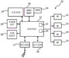
为了使本发明具体化,图1示出了可用于本发明的实施方式的实现中的无人机平台20的典型架构的系统示图。总体上,无人机20包括:控制系统22、一个或多个推进单元24、动力系统26、通信系统27、传感器套件28、任务计划系统29和导航系统30。无人机系统20可以与地面或基站计算机系统31(下文中被称为“地面站”)结合操作,稍后将参照图2对其进行更详细的描述。In order to embody the present invention, Figure 1 shows a system diagram of a typical architecture of an unmanned
控制系统22是主计算单元,其通过基于来自传感器套件28和导航系统30的输入控制推进单元24来控制无人机20的飞行。控制系统22可实现基于从基于地面的控制器接收到的控制输入的远程控制飞行,基于其内部任务计划算法的自主飞行,或者其中使用机载任务计划和基于地面的方向的共混的半自主飞行。控制系统22的主要职责是作为下层控制器,负责基于远程控制行动或者基于自行生成的飞行方向的无人机的位置控制(高度和横向位置)、姿态控制(俯仰、滚动和偏航)和速率控制(水平和竖直速度)。控制系统22包括具有处理器32和存储器34的合适处理环境,处理器32和存储器34具有诸如数据总线这样的关联的机载通信功能,所以它能够与其他机载系统通信。
为了直接控制飞行剖面图,控制系统22与一个或多个推进单元24通信。这里示出了四个推进单元24,如将与无人机系统20是多旋翼机的一致。然而,更多或更少的推进单元也是适宜的。例如,自主直升机可具有单个推进单元。推进单元可以是用于为无人机提供可控制飞行的任何合适单元,并且可以是驱动合适转子叶片的电动马达,如具有可变大小和提升能力的多旋翼机典型的那样。然而,推进单元24也可以是例如燃气涡轮机或内燃发动机。For direct control of the flight profile, the
选择机载动力系统26以适合于推进单元24。例如,对于电动马达,机载动力系统26可以是电池组、燃料电池或甚至是外部动力插头,以便从外部源接收电力。相反,倘若推进单元是燃气涡轮机或ICE,动力系统26可以是机载燃料箱。The
通信系统27提供了将数据发送到无人机20外部的系统和从该系统接收数据的装置。例如,无人机20可将遥测数据发送到基站31,并且可将位置、姿态和速率数据发送到在该区域中操作的其他无人机,要么作为无人机群的部分要么被独立地操作。通信系统27还可从外部系统接收数据,并且在这种背景下,如果无人机20以远程控制飞行模式进行操作,则它可从基站接收远程控制命令。另选地,它可从基站上传任务数据。通信系统27还许可与其他无人机进行进出通信,使得飞行路径和任务目标可与它们协调,以实现共同目标。通信系统可通过本领域中已知的任何手段来引导信号,包括但不限于通过远程控制射频链路、UHF或L频带链路、微波频率链路或其他适宜数据链路、网络或通信路径的蜂窝或其他基于电话的网络。
传感器套件28可操作地连接到控制系统22,并且提供适宜的传感器数据以辅助无人机的操作。例如,传感器套件可包括接近检测器、用于定位控制的全球导航卫星系统/全球定位系统(GNSS/GPS)单元、用于执行检查和引导任务的光学相机和摄像机、惯性导航系统,这仅仅是几个实施例。通常,这种传感器套件28将适于承载特定任务所需的更多或更少的传感器。注意的是,在此背景下,GPS单元可直接从卫星接收信号以便固定无人机的位置,尽管另一种选择将是实现差分GPS系统(本领域已知),该差分GPS系统从基于地面的差分GPS信标接收信号,以便与直接GPS相比提供更高的位置精度。注意的是,这里示出的GPS单元36与导航系统30是一体的。The
任务计划系统29提供通向基站的链路,以存储已在其上生成并且无人机在使用中遵循的任务。任务计划系统29可包括合适的存储器存储和算法,以在飞行时存储、提供和生成适宜的任务目标、航路点、操作轨道线等。
导航系统30基于来自传感器套件28的GPS数据的输入,向飞行控制系统22提供关于路径跟踪的控制输入。
除上述的操作系统之外,无人机20还包括货物连接件38,货物连接件38向货物提供可释放的连接,使得例如通过操作者或者电气控制的吊钩可以将无人机连接到货物以及从货物释放无人机。传感器套件28可包括合适的负载传感器,以检测诸如货物质量和负载偏置/重心这样的货物性质。In addition to the operating system described above, the
已描述了无人机20的功能部件,现在讨论将转为如图2中所示的地面站31。地面站31为一架或多架无人机20提供基于地面的控制枢纽,并且适当地配备具有适当处理模块42和存储器存储44的计算平台40。计算平台实现合适的地面站软件包46,以提供用于控制和协调一架或多架无人机的适宜地面站设施。例如,软件包可包括遥测进给、状态信息更新、第一人称视觉(FPV)进给、任务计划界面和算法等。提供用户界面48,以使用户/操作员能够查看与无人机系统相关的数据并且将控制和参数数据输入地面站。用户界面48可包括显示屏和音频输出以及诸如键盘、操纵杆、鼠标、屏幕上按钮或这些的组合这样的用户输入装置。地面站还具有通信系统50,以便向一架或多架无人机发送数据并从一架或多架无人机接收数据。Having described the functional components of the
应该理解,无人机系统20的以上描述仅旨在作为自主驾驶飞行器的主要部件的实施例,并且其他部件也可以被包括在典型系统中。通常,应该注意,用于本发明的实施方式的无人机是已知的,并且能够在远程控制飞行模式、半自主和全自主飞行模式下执行,并且能够以协调的方式与其他无人机处于固定位置关系地执行操纵。It should be understood that the above description of the
合适类型的无人机是格里夫无人机航空公司(Griff Aviation)的格里夫系列无人机。A suitable type of drone is the Griff series of drones from Griff Aviation.
以上的讨论集中在可用于给出本发明上下文的无人机系统的实施例。现在,讨论将集中在无人机系统的特定功能。The above discussion has focused on embodiments of unmanned aerial systems that may be used to give the context of the present invention. Now, the discussion will focus on the specific capabilities of UAS.
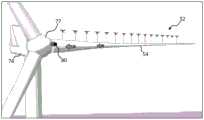
图3示出了本发明的实施方式,其中使用多架无人机52来提升风力涡轮机53的风力涡轮机叶片54,在附图的背景中可看到风力涡轮机53的塔架。无人机52中的每架可具有如上所述的系统级架构。可利用对无人机群的适当控制和再充电设施,从诸如卡车或船这样的移动基地部署无人机。地面站31可被安置在移动基地上。这里,无人机被示出为已被部署并移动到靠近风力涡轮机叶片54的相应位置,并且被示出为通过包括相应的支撑线55(为了清晰起见,仅示出了其中两个)连同基于地面的叶片支撑件56将叶片54支撑在地面上方。Figure 3 shows an embodiment of the invention in which a plurality of
为了提升叶片54,在该实施方式中,必须以协调方式控制无人机52,以产生所需的提升力使叶片54的质量升空。可实现此的一种方式是通过操作员控制无人机52的定位的手动过程。在该实施方式中,每架无人机一个操作员的方法将是不切实际的,所以在手动过程中,多架无人机52中的一架可被指定为“主无人机”,而其他单元将被指定为“从属无人机”。因此,操作员将专注于将主无人机相对于叶片定位在正确的位置和定向,而其他无人机将自动将自身相对于主无人机定位在预定的相对位置处–注意的是,这里将主无人机指定为60。In order to lift the
无人机群中的不止一架无人机可被指定为主无人机。例如,设想到在无人机的线性飞行编队中,一条线上的第一架无人机和最后一架无人机可被指定为主无人机。通过这种方式,可直接控制两架主无人机的位置,而从属无人机的位置可自行调节到两架主无人机之间的分级或分布位置。以这样的主-从属关系,一架或多架主无人机将被构造成经由合适的数据进给信号(包括高度数据、速率数据、水平位置数据)将飞行信息发送到从属无人机。More than one drone in a drone swarm can be designated as the master drone. For example, imagine that in a linear flight formation of drones, the first and last drones in a line could be designated as master drones. In this way, the positions of the two master UAVs can be directly controlled, while the positions of the slave UAVs can be adjusted themselves to a hierarchical or distributed position between the two master UAVs. In such a master-slave relationship, one or more master drones will be configured to send flight information to the slave drones via suitable data feed signals (including altitude data, velocity data, horizontal position data).
设想到,控制主题可以是被提升的部件的定向和位置。例如,作为控制主题的参数可以是叶片根部的位置和叶片的中心线的定向/姿态。因此,无人机按协调飞行状态行动,以便根据操作员所发送的命令控制中心线和叶片根部位置。因此,实际上,无人机和部件被可操作地连接,以代表单个远程控制的空中系统,使得操作员只必须专注于部件的定位,并且地面站31或无人机本身对操作员评论进行解释,以便控制无人机中的每架以实现该目标。It is contemplated that the subject of control may be the orientation and position of the components being lifted. For example, parameters that are the subject of control may be the position of the root of the blade and the orientation/pose of the centerline of the blade. Therefore, the UAV acts in a coordinated flight state to control the centerline and blade root position based on commands sent by the operator. Thus, in effect, the drone and the components are operably linked to represent a single remotely controlled aerial system, so that the operator only has to focus on the positioning of the components, and the
代替手动控制,还可由地面站31基于预定的任务剖面图来自动控制无人机52。这将向无人机指示它们将要承载的负载以及所需的飞行编队或模式。例如,对于诸如风力涡轮机叶片这样的线形负载,最佳飞行模式将是将无人机布置成一条线,如图3中所示。然而,对于其他部件,例如变速箱,另一种飞行模式可能更适宜,例如,正方形或圆形布置。Instead of manual control, the
无人机52能够直接连接到叶片以便提升叶片,或者它们可附接到中间提升装置。在图2中,无人机52附接到提升框架62或“叉架”。在此实施方式中,在被命令以将它们自己定位在叶片54上方之前,无人机将首先必须联接到提升叉架62。The
有利地,提升叉架62将使由各架无人机52施加到叶片上的向上力平均化并改善控制。无人机可通过任何合适的绳索、线缆或链条连接到提升叉架62。然而,通常,相对质轻的提升线可联接在无人机52和提升叉架62之间,这简化了这些部件之间所需的连接。Advantageously, raising the
然后,在提升叉架62和叶片54之间联接提升线束。在图中,提升线束64呈现为第一悬索和第二悬索66,各悬索在朝向叶片的尖端和根部的相应位置处环绕叶片。选择悬索66的位置,以提供平衡的提升,使得叶片54在其被提升到空中时保持在预定定向。优选地,叶片54保持笔直且水平,尽管这不是必需的。提升叉架62可配备有传感器68,以检测叉架62的定向并向无人机群提供反馈路径,使得可维持正确的定位和定向。通常,提升线、绳索、线缆、带或用于提升被引导成附接到无人机或经由中间提升叉架的风力涡轮机叶片的其他材料由此可被认为是提升线束或叶片保持装置/设备。注意的是,传感器68也可定位在部件上,以提供部件的位置的直接反馈。Then, a lift harness is coupled between the
提升悬索66可由任何合适的材料制成,但是一种选择是相对宽的织造的尼龙带材料,其能够横跨足够宽的接触面分布叶片的负载,从而避免损坏叶片。带可有利地设置有高摩擦表面材料,即使在受到横向引导力时,该材料也提高悬索在叶片上维持其位置的能力。然而,当无人机操作以控制叶片的位置时,它们将对它们的实际位置变得较不敏感,因为它们将被提供连续的反馈,这将使它们对沿着叶片的它们的位置的较不敏感,例如,如果一架无人机改变位置,则其他无人机将有助于相应地进行补偿。尽管图3中示出了两条提升悬索,但可提供更多的提升悬索。The lift slings 66 may be made of any suitable material, but one option is a relatively wide woven nylon tape material capable of distributing the load of the blade across a sufficiently wide contact surface to avoid damage to the blade. The belt may advantageously be provided with a high friction surface material which improves the ability of the suspension cable to maintain its position on the blade even when subjected to lateral guiding forces. However, when the drones operate to control the position of the blades, they will become less sensitive to their actual position as they will be provided with continuous feedback which will make them more aware of their position along the blades Insensitive, e.g. if one drone changes position, the other drones will help to compensate accordingly. Although two hoisting cables are shown in Figure 3, more hoisting cables may be provided.
作为将支撑线直接附接到风力涡轮机叶片的方法的变型,替代性实施方式包括叶片可被接收在其中的管状提升袜或护套。然后,可将支撑线附接到提升袜,无人机群52能够借助提升袜将叶片提升到空中。As a variation on the method of attaching the support wire directly to the wind turbine blade, alternative embodiments include a tubular lift sock or jacket in which the blade may be received. The support wire can then be attached to a lift sock with which the
一旦无人机52联接到风力涡轮机叶片54,无人机就可随后将部件向上提升。该行为可以是响应于操作员手动控制无人机52,或者这也可通过操作员触发任务剖面图的“提升和定位”部分或阶段来实现,在该“提升和定位”部分或阶段中无人机群将部件提升并将其相对于风力涡轮机定位,以便可将其固定到位。Once the
在以上情形下,无人机群52被构造成在叶片54上执行协调的提升操纵,并且这通过使用用作在无人机52和叶片54之间的中间部件的提升叉架62来实现。在图4中示出了其中无人机群52成对布置的替代构造。在该实施方式中,每个无人机对70具有连接在它们之间的支撑线或提升悬索72,使得提升悬索72在叶片54下方延伸以对其支撑。In the above situation, the
如以上讨论的,图3和图4示出了可如何相对于风力涡轮机部件(在这种情况下为风力涡轮机叶片)控制和构造无人机群52以便将其抬离地面的两个示例方法。现在将注意力转到图5和图6,图5和图6示出了过程的后续部分,其中使风力涡轮机部件相对于风力涡轮机就位,风力涡轮机部件在该位置处可附接到风力涡轮机。As discussed above, Figures 3 and 4 illustrate two example methods of how
在图5中,无人机群52将风力涡轮机叶片54朝着风力涡轮机76的机舱74向上提升。如图中可看到的,风力涡轮机76是典型的水平轴风力涡轮机(HAWT),其中机舱74包括支撑三叶片转子78的轮毂77,这是常见的构造。轮毂77具有附接到其的两个叶片,并且被设置成处于角度位置,在该角度位置,轮毂77可接收第三叶片54,第三叶片54被无人机群52在水平定向上提升。In FIG. 5 , drone swarm 52 lifts
无人机群52的定位和飞行控制通常可使用GNSS/GPS技术来实现,尽管为了确保所需的位置精度,目前设想差分GPS系统将是优选的。差分GPS技术将被技术人员很好地理解。尽管此系统自身可能足以使无人机群52将叶片54定位在轮毂77旁边的正确位置,使得叶片根部直接邻近轮毂的根部承座,进一步的引导可以是有用的。因此,在图5和图6的实施方式中,该系统包括引导系统80,引导系统80可操作以向无人机52提供关于风力涡轮机部件54相对于风力涡轮机的相对位置的数据/信息,以精确地定位和对接部件。Positioning and flight control of the
可按各种方式呈现引导系统80。参照图7,在一个实施方式中,引导系统80可包括雷达收发器82。雷达收发器82可附接到叶片并且被定向成指向机舱74的轮毂77,使得其将轮毂77上的圆形叶片根部承座视为目标84。引导系统80将具有适当的知识数据库,以识别轮毂的形状并将飞行路径信息提供给无人机群52和/或地面站31,使得无人机能够适当地定位自己。代替雷达,基于激光雷达(光检测和测距)的引导系统也被认为是合适的。The
作为以上方法的替代,可替代地将雷达收发器82定位在轮毂77中,使得风力涡轮机叶片的根部成为目标84。引导系统80将直接地或经由地面站31将引导路径信息发送到无人机群52,以便将风力涡轮机部件引导到位。As an alternative to the above approach, the
图8示出了其中引导系统80包括光学相机86的其他替代实施方式。光学相机86可被定位在叶片54上或轮毂77中,并且可被构造成观察适当的光学目标88。因此,引导系统80能够识别光学目标88并推导关于目标的相对距离和定向的信息,以便向无人机群52和/或地面站31提供合适的引导路径信息,使得无人机群能够将风力涡轮机部件引导到期望的位置。FIG. 8 shows other alternative embodiments in which the
在上述的实施方式中,将理解,风力涡轮机部件可代表供无人机提升到空中的重大负载。相对小的工具包和诸如电子单元等这样的部件可能适合用能够提升几十公斤的一个或少量几个能力相对低的无人机来提升。较大的部件可能需要诸如远程控制的重型提升直升机这样的一台或两台非常高提升能力的无人驾驶飞行器,或另选地大量工业级多旋翼机,例如,四旋翼机、五旋翼机、六旋翼机、八旋翼机等。In the above-described embodiments, it will be appreciated that the wind turbine components may represent significant loads for the drone to be lifted into the air. Relatively small kits and components such as electronic units may be suitable for lifting with one or a few relatively low-capacity drones capable of lifting tens of kilograms. Larger components may require one or two very high lift capacity unmanned aerial vehicles such as remotely controlled heavy lift helicopters, or alternatively a large number of industrial grade multi-rotors, e.g. quadrotors, pentarotors , Hexacopter, Octacopter, etc.
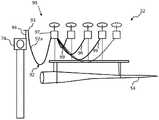
需要被提升的风力涡轮机部件的质量容易超过1吨,并且可接近10吨或更重,这将需要相对大量的多旋翼型无人驾驶飞行器,以便安全可靠地提升所述部件,从而允许例如单架无人机出现故障。随之而来的是,这种操作的动力需求将是巨大的,并且在这种提升情况下,将期望延伸无人机的飞行时间耐久性的方式。图9示出了提供对此问题的解决方案的实施方式。为了简单起见,将这些相同的附图标记用于与之前附图一样的特征。The mass of wind turbine components that need to be lifted can easily exceed 1 ton, and can approach 10 tons or more, which would require a relatively large number of multi-rotor-type unmanned aerial vehicles in order to safely and reliably lift said components, allowing for example a single A drone malfunctioned. It follows that the power requirements for such an operation will be enormous, and in such an elevated situation, a way to extend the flight-time durability of the drone will be desired. Figure 9 shows an embodiment that provides a solution to this problem. For simplicity, these same reference numbers are used for the same features as in the previous figures.
在图9中,风力涡轮机部件(在这种情况下为风力涡轮机叶片54)正被朝向机舱74提升。为了向无人机群52提供增加的飞行时间,提供了系绳系统90。系绳系统90主要被构造成向无人机群52中的无人机提供动力,但是如果合适的话,也可以向无人机群52传送数据或从无人机群52传送数据。In FIG. 9 , the wind turbine component, in this case the
系绳系统90包括脐带缆92,脐带缆92提供与无人机中的每架的动力连接。第一脐带缆92a具有第一端93,第一端93连接在设置在机舱上的动力插头94与无人机52中的第一架之间。其他脐带缆连接在相邻的无人机之间。
由于动力插头在升高的位置处被支撑在风力涡轮机机舱74上,因此可以减少需要由与其连接的无人机承载的脐带缆的质量,这增加了无人机的有效负载能力。脐带缆可以设置在卷轴或滚筒上,以根据无人机的飞行分配或缩回。Since the power plug is supported on the
注意的是,动力插头94不需要设置在机舱74上,并且其可通过其他装置设置在地面上方的位置。例如,动力插头可设置在桅杆的顶部处。桅杆可被构造成提供可变的高度-例如,它可以是充气式或伸缩式的。Note that the
在图9的实施方式中,连接到动力插头94的第一无人机被构造成通过第二脐带缆92b向另一无人机提供动力,第二脐带缆92b连接到无人机上的动力插头98。相同的构造用于在飞行编队中的相邻无人机之间“串链接”脐带缆。作为该构造的替代,第一无人机可为群中的其他无人机提供多个动力连接,由此充当动力枢纽。当然,可提供多架动力枢纽无人机,以增加可被供应动力的无人机的数目。In the embodiment of Figure 9, the first drone connected to the
安装在风力涡轮机上的动力插头94可从专用电源单元被提供电力,或者动力插头94可利用风力涡轮机的电力转换器系统,电力转换器系统已被适当地适于从电网抽取电力的任务。在无人机没有以电力的方式被提供动力而是通过诸如燃气涡轮机或往复式活塞发动机这样的内燃发动机而提供动力的替代实施方式中,动力源可以是液体燃料源,而脐带缆可将液体燃料运载到无人机。这样的优点在于,无人机不必为了提高耐用性而配备重型燃料箱。The
简要地参照图10,这是示出了为了处理风力涡轮机的部件的根据本发明的实施方式的方法100的步骤的示图。首先,从合适的基地部署102一架或多架无人驾驶飞行器或无人机,该基地可以是卡车或船上的便携式基地。无人机可按未连接的构造来部署,或者可在部署之前将它们钩接到适于提升所讨论部件的提升装置。一旦被部署,无人机就被命令和控制104,以移动到靠近风力涡轮机部件的相应位置,使得无人机可被构造成支撑该部件。这里,无人机采用固定的空运站,使得操作员能够将无人机联接到要由它们提升的任何部件。例如,单架无人机可连接到工具包,使得它可被提升并运送到在风力涡轮机的机舱中工作的人员。然而,多架无人机可连接到诸如变速箱或叶片这样的较大部件。便利地,无人机将它们自身定位在固定的飞行编队中,该飞行编队是要提升的部件特定的。例如,在风力涡轮机叶片的背景下,多架无人机可将它们自身定位在包括相对于叶片的纵向轴线对准的一个或更多个线性阵列的编队中。Referring briefly to Figure 10, this is a diagram illustrating the steps of a
一旦无人机已联接104到风力涡轮机部件,它们就能够被控制108以提升风力涡轮机部件并且相对于风力涡轮机操纵所述部件。因此,在组装和维护任务期间,可使用无人驾驶飞行器方便地提升和定位风力涡轮机部件。除了相对于风力涡轮机提升和定位风力涡轮机部件使得它们可在组装期间连接到风力涡轮机之外,无人机也可用于提升风力涡轮机部件使之远离风力涡轮机,这可能是例如在更换操作期间需要的。Once the drones have been coupled 104 to the wind turbine components, they can be controlled 108 to lift the wind turbine components and steer the components relative to the wind turbine. Thus, the unmanned aerial vehicle can be used to easily lift and position wind turbine components during assembly and maintenance tasks. In addition to lifting and positioning wind turbine components relative to the wind turbine so that they can be connected to the wind turbine during assembly, drones can also be used to lift wind turbine components away from the wind turbine, which may be required, for example, during replacement operations .
技术人员将理解,可按不脱离权利要求所限定的发明构思的情况下修改或适应这里讨论的具体实施方式。其他变型也是可能的。Skilled artisans will appreciate that the specific embodiments discussed herein may be modified or adapted without departing from the inventive concept defined in the claims. Other variants are also possible.
在与图9相似的图11中示出了一个这样的变型,使得第一无人机为其他无人机供电。为了保持一致性,在适当的地方将使用相同的编号。One such variant is shown in Figure 11, which is similar to Figure 9, so that the first drone powers the other drones. For consistency, the same numbering will be used where appropriate.
如在图9中,在图11中的实施方式中,风力涡轮机叶片54正被朝向机舱74提升。为了向无人机群52提供增加的飞行时间,提供了系绳系统90。系绳系统90主要被构造成向无人机群52中的无人机提供动力,但是如果合适的话,也可以向无人机群52传送数据或从无人机群52传送数据。As in FIG. 9 , in the embodiment of FIG. 11 , the
系绳系统90包括脐带缆92,脐带缆92向无人机中的每架提供动力连接。第一脐带缆92a具有第一端93,第一端93连接在设置在机舱上的动力插头94与无人机52中的第一无人机97之间。无人机中的第一无人机97通过单独的辅助脐带缆99向其他无人机52提供所有动力。因此,“动力源无人机”97充当动力枢纽,并且对于需要与其连接的每架无人机具有单独的动力连接。当然,可提供多架动力枢纽无人机,以增加可被供应动力的无人机的数目。这种方法意味着,第一无人机可专用于提升主脐带缆,因为需要处理大量无人机的整体动力源需求,因此主脐带缆将具有大的质量。因此,可使向其他无人机供应动力的辅助脐带缆变得更轻,因为它们只需要为无人机群中的单架无人机供应动力。
Claims (21)
Translated fromChineseApplications Claiming Priority (3)
| Application Number | Priority Date | Filing Date | Title |
|---|---|---|---|
| DKPA201770527 | 2017-06-30 | ||
| DKPA201770527 | 2017-06-30 | ||
| PCT/DK2018/050155WO2019001664A1 (en) | 2017-06-30 | 2018-06-21 | System and method for handling wind turbine components for assembly thereof |
Publications (1)
| Publication Number | Publication Date |
|---|---|
| CN110799748Atrue CN110799748A (en) | 2020-02-14 |
Family
ID=62904215
Family Applications (1)
| Application Number | Title | Priority Date | Filing Date |
|---|---|---|---|
| CN201880043535.3APendingCN110799748A (en) | 2017-06-30 | 2018-06-21 | System and method for processing wind turbine components for assembling same |
Country Status (4)
| Country | Link |
|---|---|
| US (1) | US11391267B2 (en) |
| EP (1) | EP3645871B1 (en) |
| CN (1) | CN110799748A (en) |
| WO (1) | WO2019001664A1 (en) |
Families Citing this family (6)
| Publication number | Priority date | Publication date | Assignee | Title |
|---|---|---|---|---|
| US11325702B2 (en)* | 2016-08-19 | 2022-05-10 | Motorola Solutions, Inc. | Tethered aerial drone system |
| US20220268930A1 (en)* | 2019-10-15 | 2022-08-25 | Sony Semiconductor Solutions Corporation | Ranging device and light reception method thereof |
| US12110873B2 (en)* | 2020-05-15 | 2024-10-08 | Vestas Wind Systems A/S | Nacelle for wind turbine and method for transferring components |
| US11854411B2 (en) | 2020-12-22 | 2023-12-26 | Florida Power & Light Company | Coordinating drone flights in an operating wind farm |
| US12252277B2 (en) | 2022-09-28 | 2025-03-18 | Lifting Drones, LLC | Unmanned aerial vehicle with hollow interior portion in truss |
| WO2025191188A1 (en)* | 2024-03-15 | 2025-09-18 | Imfuture - Integral Management Future Renewables, S.L. | System and method for inspection of wind-turbine blades in rotation |
Citations (7)
| Publication number | Priority date | Publication date | Assignee | Title |
|---|---|---|---|---|
| DE102012010019A1 (en)* | 2012-05-22 | 2013-11-28 | Axzion Gks Stahl + Maschinenbau Gmbh | Load carrying equipment i.e. cross element, for assembling propeller blade, of wind turbine outside of building, has wing-shaped air deflector panel regulating pre-defined layer by change of position based on environmental conditions |
| CN204342266U (en)* | 2014-11-19 | 2015-05-20 | 扬州新河水工业设备有限公司 | The automatic lifting of weight and let-down mechanism in unmanned deep-well |
| US20150158576A1 (en)* | 2013-12-09 | 2015-06-11 | The Boeing Company | Methods and apparatus to cooperatively lift a payload |
| US9205922B1 (en)* | 2013-07-17 | 2015-12-08 | The Boeing Company | Systems and methods for implementing a payload distribution system |
| US9305280B1 (en)* | 2014-12-22 | 2016-04-05 | Amazon Technologies, Inc. | Airborne fulfillment center utilizing unmanned aerial vehicles for item delivery |
| CN205633032U (en)* | 2016-05-18 | 2016-10-12 | 金陵科技学院 | Remove unmanned aerial vehicle for brick |
| US20160362180A1 (en)* | 2015-04-14 | 2016-12-15 | ETAK Systems, LLC | Using drones to lift personnel up cell towers |
Family Cites Families (18)
| Publication number | Priority date | Publication date | Assignee | Title |
|---|---|---|---|---|
| DE10209881A1 (en)* | 2002-03-06 | 2003-09-18 | Aloys Wobben | aircraft |
| EP2272754A1 (en)* | 2009-06-30 | 2011-01-12 | Vestas Wind Systems A/S | Wind turbine generator installation by airship |
| EP2270330A1 (en)* | 2009-06-30 | 2011-01-05 | Vestas Wind Systems A/S | Wind turbine generator service by airship |
| US20110084162A1 (en)* | 2009-10-09 | 2011-04-14 | Honeywell International Inc. | Autonomous Payload Parsing Management System and Structure for an Unmanned Aerial Vehicle |
| US8876571B2 (en)* | 2013-02-15 | 2014-11-04 | Disney Enterprises, Inc. | Aerial display system with marionettes articulated and supported by airborne devices |
| DE102013211751A1 (en)* | 2013-06-21 | 2014-12-24 | Wobben Properties Gmbh | Method for mounting a wind turbine rotor blade and wind turbine rotor blade |
| US9022324B1 (en)* | 2014-05-05 | 2015-05-05 | Fatdoor, Inc. | Coordination of aerial vehicles through a central server |
| US20170101177A1 (en) | 2014-06-15 | 2017-04-13 | Andrei Vladimirovitch Smirnov | Chain-Connected Micro-Areal Vehicles |
| US9760072B2 (en)* | 2014-07-03 | 2017-09-12 | David R. Hall | Secure remote operation and actuation of unmanned aerial vehicles |
| US9764839B2 (en)* | 2014-07-08 | 2017-09-19 | Todd Michael Whitaker | Tethered unmanned aerial vehicle fire fighting system |
| US10071803B2 (en) | 2015-01-16 | 2018-09-11 | International Business Machines Corporation | Package transport container and transport operations for an unmanned aerial vehicle |
| US9676481B1 (en) | 2015-03-27 | 2017-06-13 | Amazon Technologies, Inc. | Tether compensated airborne delivery |
| JP6393887B2 (en) | 2015-11-06 | 2018-09-26 | 株式会社プロドローン | Transport device and transport method |
| WO2017110743A1 (en)* | 2015-12-25 | 2017-06-29 | Ntn株式会社 | Large structure maintenance method, method for maintaining wind-power generation facility, and unmanned aircraft |
| US10421544B2 (en)* | 2016-04-08 | 2019-09-24 | Rosemount Aerospace Inc. | Systems and methods for positioning a hoist and hook |
| US10120377B2 (en)* | 2016-08-13 | 2018-11-06 | International Business Machines Corporation | Multiple unmanned aerial vehicle autonomous coordination |
| JP2020507036A (en)* | 2017-01-23 | 2020-03-05 | ラガウェイ ウィンド ベー.フェー.Lagerwey Wind B.V. | Wind power generation system with low electromagnetic interference |
| DE102017112765A1 (en)* | 2017-06-09 | 2018-12-13 | Liebherr-Werk Biberach Gmbh | Method and device for lifting a load |
- 2018
- 2018-06-21CNCN201880043535.3Apatent/CN110799748A/enactivePending
- 2018-06-21EPEP18740096.5Apatent/EP3645871B1/enactiveActive
- 2018-06-21WOPCT/DK2018/050155patent/WO2019001664A1/ennot_activeCeased
- 2018-06-21USUS16/621,293patent/US11391267B2/enactiveActive
Patent Citations (7)
| Publication number | Priority date | Publication date | Assignee | Title |
|---|---|---|---|---|
| DE102012010019A1 (en)* | 2012-05-22 | 2013-11-28 | Axzion Gks Stahl + Maschinenbau Gmbh | Load carrying equipment i.e. cross element, for assembling propeller blade, of wind turbine outside of building, has wing-shaped air deflector panel regulating pre-defined layer by change of position based on environmental conditions |
| US9205922B1 (en)* | 2013-07-17 | 2015-12-08 | The Boeing Company | Systems and methods for implementing a payload distribution system |
| US20150158576A1 (en)* | 2013-12-09 | 2015-06-11 | The Boeing Company | Methods and apparatus to cooperatively lift a payload |
| CN204342266U (en)* | 2014-11-19 | 2015-05-20 | 扬州新河水工业设备有限公司 | The automatic lifting of weight and let-down mechanism in unmanned deep-well |
| US9305280B1 (en)* | 2014-12-22 | 2016-04-05 | Amazon Technologies, Inc. | Airborne fulfillment center utilizing unmanned aerial vehicles for item delivery |
| US20160362180A1 (en)* | 2015-04-14 | 2016-12-15 | ETAK Systems, LLC | Using drones to lift personnel up cell towers |
| CN205633032U (en)* | 2016-05-18 | 2016-10-12 | 金陵科技学院 | Remove unmanned aerial vehicle for brick |
Also Published As
| Publication number | Publication date |
|---|---|
| WO2019001664A1 (en) | 2019-01-03 |
| US20200109698A1 (en) | 2020-04-09 |
| EP3645871B1 (en) | 2021-09-22 |
| EP3645871A1 (en) | 2020-05-06 |
| US11391267B2 (en) | 2022-07-19 |
Similar Documents
| Publication | Publication Date | Title |
|---|---|---|
| CN112041257B (en) | Systems and methods for handling wind turbine components for their assembly | |
| US11391267B2 (en) | System and method for handling wind turbine components for assembly thereof | |
| EP3645874B1 (en) | Method for reducing oscillations in wind turbine blades | |
| CN111512253B (en) | Active position control of rope hooks | |
| US7149611B2 (en) | Virtual sensor mast | |
| US20160159472A1 (en) | Reconfigurable unmanned aircraft system | |
| KR20220027149A (en) | Suspended Aircraft Systems with Thruster Stabilization | |
| EP3814222B1 (en) | Unmanned coaxial rotor aerial vehicle for transport of heavy loads | |
| EP3778393B1 (en) | A load carrying assembly | |
| WO2019001662A1 (en) | System and method for positioning wind turbine components | |
| US11518515B1 (en) | Auto rotating canister | |
| US11873099B2 (en) | Load carrying assembly | |
| CN111003183A (en) | Ground operation for picking from autonomous objects | |
| WO2019001665A1 (en) | System and method for handling wind turbine components | |
| EP4069586B1 (en) | An unmanned aerial vehicle | |
| WO2024226441A2 (en) | Vortex drone | |
| CN114590408B (en) | Load carrying assembly | |
| CA3101109C (en) | A load carrying assembly | |
| KR20250102233A (en) | Heavy-duty logistics transport drone equipped with autonomous transport condition judgment system |
Legal Events
| Date | Code | Title | Description |
|---|---|---|---|
| PB01 | Publication | ||
| PB01 | Publication | ||
| SE01 | Entry into force of request for substantive examination | ||
| SE01 | Entry into force of request for substantive examination | ||
| RJ01 | Rejection of invention patent application after publication | Application publication date:20200214 | |
| RJ01 | Rejection of invention patent application after publication |