CN110799126A - Cartridge Arrangement for Surgical Cutting and Fastening Instruments with Lockout Disable Features - Google Patents
Cartridge Arrangement for Surgical Cutting and Fastening Instruments with Lockout Disable FeaturesDownload PDFInfo
- Publication number
- CN110799126A CN110799126ACN201880043813.5ACN201880043813ACN110799126ACN 110799126 ACN110799126 ACN 110799126ACN 201880043813 ACN201880043813 ACN 201880043813ACN 110799126 ACN110799126 ACN 110799126A
- Authority
- CN
- China
- Prior art keywords
- cartridge
- surgical
- assembly
- received
- opening
- Prior art date
- Legal status (The legal status is an assumption and is not a legal conclusion. Google has not performed a legal analysis and makes no representation as to the accuracy of the status listed.)
- Granted
Links
Images


Classifications
- A—HUMAN NECESSITIES
- A61—MEDICAL OR VETERINARY SCIENCE; HYGIENE
- A61B—DIAGNOSIS; SURGERY; IDENTIFICATION
- A61B17/00—Surgical instruments, devices or methods
- A61B17/068—Surgical staplers, e.g. containing multiple staples or clamps
- A61B17/072—Surgical staplers, e.g. containing multiple staples or clamps for applying a row of staples in a single action, e.g. the staples being applied simultaneously
- A61B17/07207—Surgical staplers, e.g. containing multiple staples or clamps for applying a row of staples in a single action, e.g. the staples being applied simultaneously the staples being applied sequentially
- A—HUMAN NECESSITIES
- A61—MEDICAL OR VETERINARY SCIENCE; HYGIENE
- A61B—DIAGNOSIS; SURGERY; IDENTIFICATION
- A61B18/00—Surgical instruments, devices or methods for transferring non-mechanical forms of energy to or from the body
- A61B18/04—Surgical instruments, devices or methods for transferring non-mechanical forms of energy to or from the body by heating
- A61B18/12—Surgical instruments, devices or methods for transferring non-mechanical forms of energy to or from the body by heating by passing a current through the tissue to be heated, e.g. high-frequency current
- A61B18/14—Probes or electrodes therefor
- A61B18/1442—Probes having pivoting end effectors, e.g. forceps
- A61B18/1445—Probes having pivoting end effectors, e.g. forceps at the distal end of a shaft, e.g. forceps or scissors at the end of a rigid rod
- A—HUMAN NECESSITIES
- A61—MEDICAL OR VETERINARY SCIENCE; HYGIENE
- A61B—DIAGNOSIS; SURGERY; IDENTIFICATION
- A61B17/00—Surgical instruments, devices or methods
- A61B17/28—Surgical forceps
- A61B17/29—Forceps for use in minimally invasive surgery
- A61B17/295—Forceps for use in minimally invasive surgery combined with cutting implements
- A—HUMAN NECESSITIES
- A61—MEDICAL OR VETERINARY SCIENCE; HYGIENE
- A61B—DIAGNOSIS; SURGERY; IDENTIFICATION
- A61B17/00—Surgical instruments, devices or methods
- A61B2017/00017—Electrical control of surgical instruments
- A—HUMAN NECESSITIES
- A61—MEDICAL OR VETERINARY SCIENCE; HYGIENE
- A61B—DIAGNOSIS; SURGERY; IDENTIFICATION
- A61B17/00—Surgical instruments, devices or methods
- A61B2017/00017—Electrical control of surgical instruments
- A61B2017/00022—Sensing or detecting at the treatment site
- A61B2017/00026—Conductivity or impedance, e.g. of tissue
- A—HUMAN NECESSITIES
- A61—MEDICAL OR VETERINARY SCIENCE; HYGIENE
- A61B—DIAGNOSIS; SURGERY; IDENTIFICATION
- A61B17/00—Surgical instruments, devices or methods
- A61B2017/00017—Electrical control of surgical instruments
- A61B2017/00022—Sensing or detecting at the treatment site
- A61B2017/00075—Motion
- A—HUMAN NECESSITIES
- A61—MEDICAL OR VETERINARY SCIENCE; HYGIENE
- A61B—DIAGNOSIS; SURGERY; IDENTIFICATION
- A61B17/00—Surgical instruments, devices or methods
- A61B2017/00017—Electrical control of surgical instruments
- A61B2017/00022—Sensing or detecting at the treatment site
- A61B2017/00084—Temperature
- A—HUMAN NECESSITIES
- A61—MEDICAL OR VETERINARY SCIENCE; HYGIENE
- A61B—DIAGNOSIS; SURGERY; IDENTIFICATION
- A61B17/00—Surgical instruments, devices or methods
- A61B2017/00017—Electrical control of surgical instruments
- A61B2017/00115—Electrical control of surgical instruments with audible or visual output
- A61B2017/00119—Electrical control of surgical instruments with audible or visual output alarm; indicating an abnormal situation
- A—HUMAN NECESSITIES
- A61—MEDICAL OR VETERINARY SCIENCE; HYGIENE
- A61B—DIAGNOSIS; SURGERY; IDENTIFICATION
- A61B17/00—Surgical instruments, devices or methods
- A61B2017/00017—Electrical control of surgical instruments
- A61B2017/00115—Electrical control of surgical instruments with audible or visual output
- A61B2017/00128—Electrical control of surgical instruments with audible or visual output related to intensity or progress of surgical action
- A—HUMAN NECESSITIES
- A61—MEDICAL OR VETERINARY SCIENCE; HYGIENE
- A61B—DIAGNOSIS; SURGERY; IDENTIFICATION
- A61B17/00—Surgical instruments, devices or methods
- A61B17/00234—Surgical instruments, devices or methods for minimally invasive surgery
- A61B2017/00353—Surgical instruments, devices or methods for minimally invasive surgery one mechanical instrument performing multiple functions, e.g. cutting and grasping
- A—HUMAN NECESSITIES
- A61—MEDICAL OR VETERINARY SCIENCE; HYGIENE
- A61B—DIAGNOSIS; SURGERY; IDENTIFICATION
- A61B17/00—Surgical instruments, devices or methods
- A61B2017/00367—Details of actuation of instruments, e.g. relations between pushing buttons, or the like, and activation of the tool, working tip, or the like
- A61B2017/00398—Details of actuation of instruments, e.g. relations between pushing buttons, or the like, and activation of the tool, working tip, or the like using powered actuators, e.g. stepper motors, solenoids
- A—HUMAN NECESSITIES
- A61—MEDICAL OR VETERINARY SCIENCE; HYGIENE
- A61B—DIAGNOSIS; SURGERY; IDENTIFICATION
- A61B17/00—Surgical instruments, devices or methods
- A61B2017/0046—Surgical instruments, devices or methods with a releasable handle; with handle and operating part separable
- A—HUMAN NECESSITIES
- A61—MEDICAL OR VETERINARY SCIENCE; HYGIENE
- A61B—DIAGNOSIS; SURGERY; IDENTIFICATION
- A61B17/00—Surgical instruments, devices or methods
- A61B2017/00477—Coupling
- A—HUMAN NECESSITIES
- A61—MEDICAL OR VETERINARY SCIENCE; HYGIENE
- A61B—DIAGNOSIS; SURGERY; IDENTIFICATION
- A61B17/00—Surgical instruments, devices or methods
- A61B2017/00681—Aspects not otherwise provided for
- A61B2017/00734—Aspects not otherwise provided for battery operated
- A—HUMAN NECESSITIES
- A61—MEDICAL OR VETERINARY SCIENCE; HYGIENE
- A61B—DIAGNOSIS; SURGERY; IDENTIFICATION
- A61B17/00—Surgical instruments, devices or methods
- A61B17/068—Surgical staplers, e.g. containing multiple staples or clamps
- A61B17/072—Surgical staplers, e.g. containing multiple staples or clamps for applying a row of staples in a single action, e.g. the staples being applied simultaneously
- A61B2017/07214—Stapler heads
- A61B2017/07257—Stapler heads characterised by its anvil
- A—HUMAN NECESSITIES
- A61—MEDICAL OR VETERINARY SCIENCE; HYGIENE
- A61B—DIAGNOSIS; SURGERY; IDENTIFICATION
- A61B17/00—Surgical instruments, devices or methods
- A61B17/068—Surgical staplers, e.g. containing multiple staples or clamps
- A61B17/072—Surgical staplers, e.g. containing multiple staples or clamps for applying a row of staples in a single action, e.g. the staples being applied simultaneously
- A61B2017/07214—Stapler heads
- A61B2017/07271—Stapler heads characterised by its cartridge
- A—HUMAN NECESSITIES
- A61—MEDICAL OR VETERINARY SCIENCE; HYGIENE
- A61B—DIAGNOSIS; SURGERY; IDENTIFICATION
- A61B17/00—Surgical instruments, devices or methods
- A61B17/068—Surgical staplers, e.g. containing multiple staples or clamps
- A61B17/072—Surgical staplers, e.g. containing multiple staples or clamps for applying a row of staples in a single action, e.g. the staples being applied simultaneously
- A61B2017/07214—Stapler heads
- A61B2017/07285—Stapler heads characterised by its cutter
- A—HUMAN NECESSITIES
- A61—MEDICAL OR VETERINARY SCIENCE; HYGIENE
- A61B—DIAGNOSIS; SURGERY; IDENTIFICATION
- A61B17/00—Surgical instruments, devices or methods
- A61B17/28—Surgical forceps
- A61B17/29—Forceps for use in minimally invasive surgery
- A61B2017/2926—Details of heads or jaws
- A61B2017/2927—Details of heads or jaws the angular position of the head being adjustable with respect to the shaft
- A—HUMAN NECESSITIES
- A61—MEDICAL OR VETERINARY SCIENCE; HYGIENE
- A61B—DIAGNOSIS; SURGERY; IDENTIFICATION
- A61B18/00—Surgical instruments, devices or methods for transferring non-mechanical forms of energy to or from the body
- A61B2018/00053—Mechanical features of the instrument of device
- A61B2018/00172—Connectors and adapters therefor
- A61B2018/00178—Electrical connectors
- A—HUMAN NECESSITIES
- A61—MEDICAL OR VETERINARY SCIENCE; HYGIENE
- A61B—DIAGNOSIS; SURGERY; IDENTIFICATION
- A61B18/00—Surgical instruments, devices or methods for transferring non-mechanical forms of energy to or from the body
- A61B2018/00571—Surgical instruments, devices or methods for transferring non-mechanical forms of energy to or from the body for achieving a particular surgical effect
- A61B2018/00607—Coagulation and cutting with the same instrument
- A—HUMAN NECESSITIES
- A61—MEDICAL OR VETERINARY SCIENCE; HYGIENE
- A61B—DIAGNOSIS; SURGERY; IDENTIFICATION
- A61B18/00—Surgical instruments, devices or methods for transferring non-mechanical forms of energy to or from the body
- A61B18/04—Surgical instruments, devices or methods for transferring non-mechanical forms of energy to or from the body by heating
- A61B18/12—Surgical instruments, devices or methods for transferring non-mechanical forms of energy to or from the body by heating by passing a current through the tissue to be heated, e.g. high-frequency current
- A61B18/14—Probes or electrodes therefor
- A61B18/1442—Probes having pivoting end effectors, e.g. forceps
- A61B2018/1452—Probes having pivoting end effectors, e.g. forceps including means for cutting
- A—HUMAN NECESSITIES
- A61—MEDICAL OR VETERINARY SCIENCE; HYGIENE
- A61B—DIAGNOSIS; SURGERY; IDENTIFICATION
- A61B18/00—Surgical instruments, devices or methods for transferring non-mechanical forms of energy to or from the body
- A61B18/04—Surgical instruments, devices or methods for transferring non-mechanical forms of energy to or from the body by heating
- A61B18/12—Surgical instruments, devices or methods for transferring non-mechanical forms of energy to or from the body by heating by passing a current through the tissue to be heated, e.g. high-frequency current
- A61B18/14—Probes or electrodes therefor
- A61B2018/1495—Electrodes being detachable from a support structure
Landscapes
- Health & Medical Sciences (AREA)
- Surgery (AREA)
- Life Sciences & Earth Sciences (AREA)
- Engineering & Computer Science (AREA)
- Biomedical Technology (AREA)
- Nuclear Medicine, Radiotherapy & Molecular Imaging (AREA)
- Heart & Thoracic Surgery (AREA)
- Medical Informatics (AREA)
- Molecular Biology (AREA)
- Animal Behavior & Ethology (AREA)
- General Health & Medical Sciences (AREA)
- Public Health (AREA)
- Veterinary Medicine (AREA)
- Otolaryngology (AREA)
- Plasma & Fusion (AREA)
- Physics & Mathematics (AREA)
- Surgical Instruments (AREA)
Abstract
Description
Translated fromChinese技术领域technical field
本公开涉及外科器械,并且在各种情况下,涉及被设计成用于缝合和切割组织的外科缝合和切割器械及其钉仓。The present disclosure relates to surgical instruments and, in various instances, surgical stapling and cutting instruments and staple cartridges thereof designed for stapling and cutting tissue.
背景技术Background technique
在外科器械中,控制切割构件何时可被推进穿过端部执行器可能是有用的。为了控制切割构件何时可被推进,外科器械可提供一种闭锁机构,以防止在各种情况下切割构件在钉/紧固件仓中的推进。用于钉/紧固件仓的闭锁机构机械地防止切割构件通过接合切割构件的一部分来推进,以禁止远侧移动。当外科仓尚未插入端部执行器中、未适当地插入端部执行器中时,或者当钉/紧固件仓被耗尽时,防止切割构件的推进可能是有用的。In surgical instruments, it may be useful to control when a cutting member can be advanced through an end effector. To control when the cutting member may be advanced, the surgical instrument may provide a latching mechanism to prevent advancement of the cutting member within the staple/fastener cartridge under various circumstances. A latching mechanism for the staple/fastener cartridge mechanically prevents advancement of the cutting member by engaging a portion of the cutting member to inhibit distal movement. It may be useful to prevent advancement of the cutting member when the surgical cartridge has not been inserted into the end effector, is not properly inserted into the end effector, or when the staple/fastener cartridge is depleted.
发明内容SUMMARY OF THE INVENTION
在一个方面,一种外科仓组件包括近侧端部、远侧端部和细长通道。所述细长通道包括基部和所述基部内的至少一个开口。所述外科仓组件还包括被构造成能够可移除地接纳在所述细长通道内的仓体和被构造成能够接纳切割构件的狭槽。此外,所述外科仓组件包括从所述仓体的近侧端部延伸的至少一个闭锁突片,其中所述至少一个闭锁突片被构造成能够在所述仓体被接纳在所述细长通道内时覆盖所述至少一个开口,并且其中所述至少一个闭锁突片禁用闭锁机构以允许所述切割构件朝远侧推进穿过所述狭槽。In one aspect, a surgical cartridge assembly includes a proximal end, a distal end, and an elongated channel. The elongated channel includes a base and at least one opening in the base. The surgical cartridge assembly also includes a cartridge body configured to be removably received within the elongated channel and a slot configured to receive a cutting member. Additionally, the surgical cartridge assembly includes at least one latching tab extending from a proximal end of the cartridge body, wherein the at least one latching tab is configured to be received in the elongated body when the cartridge body The at least one opening is covered when in the channel, and wherein the at least one latching tab disables the latching mechanism to allow the cutting member to be advanced distally through the slot.
在另一方面,一种用于外科器械的端部执行器包括近侧端部、远侧端部、第一钳口和第二钳口。所述第二钳口包括细长通道,所述细长通道包括基部,其中所述细长通道的所述基部包括第一开口和第二开口。所述端部执行器还包括被构造成能够可移除地接纳在所述细长通道内的外科仓,所述外科仓包括仓体和被构造成能够接纳切割构件的狭槽。所述外科仓还包括:第一突片,所述第一突片在所述狭槽的第一侧上从所述仓体的所述近侧端部延伸,其中所述第一突片被构造成能够在所述外科仓被接纳在所述细长通道内时覆盖所述第一开口和所述第一凸缘;和第二突片,所述第二突片在所述狭槽的第二侧上从所述仓体的所述近侧端部延伸,其中所述第二突片被构造成能够在所述外科仓被接纳在所述细长通道内时覆盖所述第二开口和所述第二凸缘,并且其中所述第一突片和所述第二突片禁用闭锁机构以允许切割构件朝远侧推进穿过所述狭槽。In another aspect, an end effector for a surgical instrument includes a proximal end, a distal end, a first jaw, and a second jaw. The second jaw includes an elongated channel including a base, wherein the base of the elongated channel includes a first opening and a second opening. The end effector also includes a surgical cartridge configured to be removably received within the elongated channel, the surgical cartridge including a cartridge body and a slot configured to receive a cutting member. The surgical cartridge further includes a first tab extending from the proximal end of the cartridge body on a first side of the slot, wherein the first tab is is configured to cover the first opening and the first flange when the surgical cartridge is received within the elongated channel; and a second tab over the slot. Extending from the proximal end of the cartridge body on a second side, wherein the second tab is configured to cover the second opening when the surgical cartridge is received within the elongated channel and the second flange, and wherein the first tab and the second tab disable a latching mechanism to allow the cutting member to be advanced distally through the slot.
在另一方面,一种外科仓组件包括近侧端部、远侧端部和细长通道。所述细长通道包括基部、第一开口和第二开口。所述外科仓组件还包括被构造成能够可移除地接纳在所述细长通道内的外科仓。所述外科仓包括仓体、被构造成能够接纳切割构件的纵向狭槽、第一闭锁突出部和第二闭锁突出部。所述第一闭锁突出部在所述狭槽的第一侧上从所述仓体的所述近侧端部朝近侧延伸,其中所述第一闭锁突出部被构造成能够在所述外科仓被接纳在所述细长通道内时覆盖所述第一开口。所述第二闭锁突出部在所述狭槽的第二侧上从所述仓体的所述近侧端部朝近侧延伸,其中所述第二闭锁突出部被构造成能够在所述外科仓被接纳在所述细长通道内时覆盖所述第二开口,并且其中所述第一闭锁突出部和所述第二闭锁突出部禁用闭锁机构以允许切割构件朝远侧推进穿过所述狭槽。In another aspect, a surgical cartridge assembly includes a proximal end, a distal end, and an elongated channel. The elongated channel includes a base, a first opening, and a second opening. The surgical cartridge assembly also includes a surgical cartridge configured to be removably received within the elongated channel. The surgical cartridge includes a cartridge body, a longitudinal slot configured to receive a cutting member, a first latching tab, and a second latching tab. The first latching tab extends proximally from the proximal end of the cartridge body on a first side of the slot, wherein the first latching tab is configured to A cartridge covers the first opening when received within the elongated channel. The second latching tab extends proximally from the proximal end of the cartridge body on a second side of the slot, wherein the second latching tab is configured to A cartridge covers the second opening when received within the elongated channel, and wherein the first latching tab and the second latching tab disable a latching mechanism to allow a cutting member to be advanced distally through the slot.
附图说明Description of drawings
本文所述方面的新颖特征在所附权利要求书中进行了详细描述。然而,关于组织和操作方法的这些方面可结合附图参考下述说明更好地理解。The novel features of the aspects described herein are set forth with particularity in the appended claims. However, these aspects regarding organization and methods of operation may be better understood with reference to the following description taken in conjunction with the accompanying drawings.
图1为根据本公开的一个方面的外科系统的透视图,该外科系统包括联接到可互换外科工具组件的柄部组件,该可互换外科工具组件被配置为能够结合常规外科钉/紧固件仓和射频(RF)仓使用。1 is a perspective view of a surgical system including a handle assembly coupled to an interchangeable surgical tool assembly configured to be capable of incorporating conventional surgical staples/tighteners according to one aspect of the present disclosure Firmware bin and radio frequency (RF) bin are used.
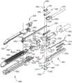
图2为根据本公开的一个方面的图1的外科系统的分解透视组装视图。2 is an exploded perspective assembled view of the surgical system of FIG. 1 according to one aspect of the present disclosure.
图3为根据本公开的一个方面的图1和图2的柄部组件和可互换外科工具组件的部分的另一分解透视组装视图。3 is another exploded perspective assembled view of portions of the handle assembly and interchangeable surgical tool assembly of FIGS. 1 and 2, according to one aspect of the present disclosure.
图4为根据本公开的一个方面的图1-图3的可互换外科工具组件的近侧部分的分解组装视图。4 is an exploded assembled view of the proximal portion of the interchangeable surgical tool assembly of FIGS. 1-3, according to one aspect of the present disclosure.
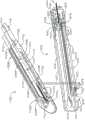
图5为根据本公开的一个方面的图1-图5的可互换外科工具组件的远侧部分的另一分解组装视图。5 is another exploded assembled view of the distal portion of the interchangeable surgical tool assembly of FIGS. 1-5 according to one aspect of the present disclosure.
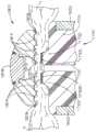
图6为根据本公开的一个方面的图1-图5示出的其中支撑有RF仓并且具有夹持在仓与砧座之间的组织的端部执行器的局部剖视图。6 is a partial cross-sectional view of the end effector shown in FIGS. 1-5 with an RF cartridge supported therein and with tissue clamped between the cartridge and the anvil, according to one aspect of the present disclosure.
图7为根据本公开的一个方面的图6的砧座的局部剖视图。7 is a partial cross-sectional view of the anvil of FIG. 6 according to one aspect of the present disclosure.
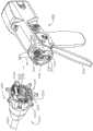
图8为根据本公开的一个方面的图1-图5的可互换外科工具组件的一部分的另一分解组装视图。8 is another exploded assembly view of a portion of the interchangeable surgical tool assembly of FIGS. 1-5 according to one aspect of the present disclosure.
图9为根据本公开的一个方面的图1和图2的可互换外科工具组件和柄部组件的另一分解组装视图。9 is another exploded assembly view of the interchangeable surgical tool assembly and handle assembly of FIGS. 1 and 2, according to one aspect of the present disclosure.
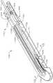
图10为根据本公开的一个方面的图1至图5的可互换外科工具组件的RF仓和细长通道的透视图。10 is a perspective view of the RF cartridge and elongated channel of the interchangeable surgical tool assembly of FIGS. 1-5 according to one aspect of the present disclosure.
图11为根据本公开的一个方面的具有刀构件方面的图10的RF仓和细长通道的部分的局部透视图。11 is a partial perspective view of a portion of the RF cartridge and elongated channel of FIG. 10 with a blade member aspect in accordance with one aspect of the present disclosure.
图12为根据本公开的一个方面的安装在FIG. 12 is an illustration of an installation in accordance with one aspect of the present disclosure.
图10所示的细长通道中的RF仓的另一透视图,并且示出柔性轴电路布置的一部分。Another perspective view of the RF cartridge in the elongated channel shown in Figure 10 and showing a portion of the flexible shaft circuit arrangement.
图13为根据本公开的一个方面的沿图12中的线13-13截取的图12的RF仓和细长通道的横截面端视图。13 is a cross-sectional end view of the RF cartridge and elongated channel of FIG. 12 taken along line 13-13 in FIG. 12 in accordance with one aspect of the present disclosure.
图14为根据本公开的一个方面的图1和图5的可互换外科工具组件的一部分的俯视剖视图,其中该可互换外科工具组件的端部执行器处于关节运动位置。14 is a top cross-sectional view of a portion of the interchangeable surgical tool assembly of FIGS. 1 and 5 with the end effector of the interchangeable surgical tool assembly in an articulated position, according to one aspect of the present disclosure.
图15为根据本公开的一个方面的板载电路板布置和RF发生器加型配置的透视图。15 is a perspective view of an on-board circuit board arrangement and RF generator retrofit configuration in accordance with one aspect of the present disclosure.
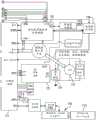
图16A-图16B为根据本公开的一个方面的跨越两个图页的图1的外科器械的控制电路的框图。16A-16B are block diagrams of control circuitry of the surgical instrument of FIG. 1 across two pages, according to one aspect of the present disclosure.
图17为根据本公开的一个方面的图1的外科器械的控制电路的框图,其示出柄部组件与功率组件之间以及柄部组件与可互换轴组件之间的接口。17 is a block diagram of the control circuitry of the surgical instrument of FIG. 1 showing the interface between the handle assembly and the power assembly and between the handle assembly and the interchangeable shaft assembly, according to one aspect of the present disclosure.
图18为根据本公开的一个方面的被构造成能够控制各种功能的外科器械的示意图。18 is a schematic illustration of a surgical instrument configured to control various functions in accordance with one aspect of the present disclosure.
图19为根据本公开的一个方面的图1-图5的可互换外科工具组件的钉仓的透视图。19 is a perspective view of a staple cartridge of the interchangeable surgical tool assembly of FIGS. 1-5, according to one aspect of the present disclosure.
说明书manual
本申请的申请人拥有于与其同时提交且各自全文以引用方式并入本文的以下专利申请:The applicant of the present application has the following patent applications filed concurrently therewith and each of which is incorporated herein by reference in its entirety:
由发明人Jeffrey D.Messerly等人于2017年6月28日提交的标题为SURGICALSYSTEM COUPLABLE WITH STAPLE CARTRIDGE AND RADIO FREQUENCY CARTRIDGE,ANDMETHOD OF USING SAME的代理人案卷号END8184USNP/170063;Attorney Docket No. END8184USNP/170063 entitled SURGICAL SYSTEM COUPLABLE WITH STAPLE CARTRIDGE AND RADIO FREQUENCY CARTRIDGE, ANDMETHOD OF USING SAME, filed by inventor Jeffrey D. Messerly et al. on June 28, 2017;
由发明人Jeffrey D.Messerly等人于2017年6月28日提交的标题为SYSTEMS ANDMETHODS OF DISPLAYING SURGICAL INSTRUMENT STATUS的代理人案卷号END8183USNP/170064;Attorney Docket No. END8183USNP/170064, titled SYSTEMS ANDMETHODS OF DISPLAYING SURGICAL INSTRUMENT STATUS, filed June 28, 2017 by inventor Jeffrey D. Messerly et al;
由发明人Jeffrey D.Messerly等人在2017年6月28日提交的标题为SHAFT MODULECIRCUITRY ARRANGEMENTS的代理人案卷号END8190USNP/170065;Attorney Docket No. END8190USNP/170065, titled SHAFT MODULECIRCUITRY ARRANGEMENTS, filed June 28, 2017 by inventor Jeffrey D. Messerly et al;
由发明人Jeffrey D.Messerly等人于2017年6月28日提交的标题为SYSTEMS ANDMETHODS FOR CONTROLLING CONTROL CIRCUITS FOR INDEPENDENT ENERGY DELIVERY OVERSEGMENTED SECTIONS的代理人案卷号END8189USNP/170066;Attorney Docket No. END8189USNP/170066, titled SYSTEMS ANDMETHODS FOR CONTROLLING CONTROL CIRCUITS FOR INDEPENDENT ENERGY DELIVERY OVERSEGMENTED SECTIONS, filed by inventor Jeffrey D. Messerly et al. on June 28, 2017;
由发明人Jeffrey D.Messerly等人在2017年6月28日提交的标题为FLEXIBLECIRCUIT ARRANGEMENT FOR SURGICAL FASTENING INSTRUMENTS的代理人案卷号END8185USNP/170067;Attorney Docket No. END8185USNP/170067, titled FLEXIBLECIRCUIT ARRANGEMENT FOR SURGICAL FASTENING INSTRUMENTS, filed June 28, 2017 by inventor Jeffrey D. Messerly et al;
由发明人Jeffrey D.Messerly等人于2017年6月28日提交的标题为SURGICALSYSTEM COUPLEABLE WITH STAPLE CARTRIDGE AND RADIO FREQUENCY CARTRIDGE,ANDHAVING A PLURALITY OF RADIO-FREQUENCY ENERGY RETURN PATHS的代理人案卷号END8188USNP/170068。Attorney Docket No. END8188USNP/170068 entitled SURGICAL SYSTEM COUPLEABLE WITH STAPLE CARTRIDGE AND RADIO FREQUENCY CARTRIDGE, ANDHAVING A PLURALITY OF RADIO-FREQUENCY ENERGY RETURN PATHS, filed by inventor Jeffrey D. Messerly et al. on June 28, 2017.
由发明人David C.Yates等人于2017年6月28日提交的标题为SYSTEMS ANDMETHODS FOR CONTROLLING CONTROL CIRCUITS FOR AN INDEPENDENT ENERGY DELIVERYOVER SEGMENTED SECTIONS的代理人案卷号END8181USNP/170069;Attorney Docket No. END8181USNP/170069, titled SYSTEMS ANDMETHODS FOR CONTROLLING CONTROL CIRCUITS FOR AN INDEPENDENT ENERGY DELIVERYOVER SEGMENTED SECTIONS, filed by inventor David C. Yates et al. on June 28, 2017;
由发明人Tamara Widenhouse等人于2017年6月28日提交的标题为SURGICAL ENDEFFECTOR FOR APPLYING ELECTROSURGICAL ENERGY TO DIFFERENT ELECTRODES ONDIFFERENT TIME PERIODS的代理人案卷号END8187USNP/170070;Attorney Docket No. END8187USNP/170070, titled SURGICAL ENDEFFECTOR FOR APPLYING ELECTROSURGICAL ENERGY TO DIFFERENT ELECTRODES ONDIFFERENT TIME PERIODS, filed by inventors Tamara Widenhouse et al. on June 28, 2017;
由发明人Tamara Widenhouse等人于2017年6月28日提交的标题为ELECTROSURGICAL CARTRIDGE FOR USE IN THIN PROFILE SURGICAL CUTTING ANDSTAPLING INSTRUMENT的代理人案卷号END8182USNP/170071;Attorney Docket No. END8182USNP/170071, titled ELECTROSURGICAL CARTRIDGE FOR USE IN THIN PROFILE SURGICAL CUTTING ANDSTAPLING INSTRUMENT, filed by inventors Tamara Widenhouse et al. on June 28, 2017;
由发明人Frederick E.Shelton,IV等人于2017年6月28日提交的标题为SURGICALEND EFFECTOR TO ADJUST JAW COMPRESSION的代理人案卷号END8186USNP/170072;Attorney Docket No. END8186USNP/170072, titled SURGICALEND EFFECTOR TO ADJUST JAW COMPRESSION, filed June 28, 2017 by inventor Frederick E. Shelton, IV et al;
由发明人Jeffrey D.Messerly等人于2017年6月28日提交的标题为SURGICALCUTTING AND FASTENING INSTRUMENTS WITH DUAL POWER SOURCES的代理人案卷号END8229USNP/170074。Attorney Docket No. END8229USNP/170074, entitled SURGICAL CUTTING AND FASTENING INSTRUMENTS WITH DUAL POWER SOURCES, filed June 28, 2017, by inventor Jeffrey D. Messerly et al.
电外科装置可用于许多外科手术中。电外科装置可向组织施加电能以便对组织进行处理。电外科装置可包括具有远侧安装的端部执行器的器械,该端部执行器包括一个或多个电极。端部执行器可抵靠组织定位,使得电流可被引入组织中。电外科装置可被配置用于单极或双极操作。在单极操作期间,电流可通过端部执行器上的有源(或源)电极被引入组织中并通过返回电极返回。返回电极可为接地板,并且单独地位于患者身体上。在双极操作期间,电流可分别通过端部执行器的有源电极和返回电极被引入组织中并从组织返回。Electrosurgical devices can be used in many surgical procedures. Electrosurgical devices can apply electrical energy to tissue in order to treat the tissue. An electrosurgical device may include an instrument having a distally mounted end effector that includes one or more electrodes. The end effector can be positioned against the tissue so that electrical current can be introduced into the tissue. Electrosurgical devices can be configured for monopolar or bipolar operation. During monopolar operation, current may be introduced into the tissue through the active (or source) electrode on the end effector and returned through the return electrode. The return electrode can be a ground plate and is located solely on the patient's body. During bipolar operation, electrical current may be introduced into and returned from the tissue through the active and return electrodes of the end effector, respectively.
端部执行器可包括两个或更多个钳口构件。该钳口构件中的至少一个可具有至少一个电极。至少一个钳口可能够从与相对钳口间隔开以用于接纳组织的位置移动到钳口构件之间的空间小于第一位置的空间的位置。可移动钳口的这种移动可压缩保持在其间的组织。由流过组织的电流所生成的热结合通过钳口移动实现的压缩可在组织内和/或在组织之间形成止血密封,并因此可尤其适用于例如密封血管。端部执行器可包括切割构件。该切割构件可能够相对于组织和电极移动以横切组织。The end effector may include two or more jaw members. At least one of the jaw members may have at least one electrode. At least one jaw may be movable from a position spaced apart from the opposing jaw for receiving tissue to a position where the space between the jaw members is less than the space of the first position. This movement of the movable jaws can compress the tissue held therebetween. The compression achieved by the movement of the jaws in combination with the heat generated by the electrical current flowing through the tissue can form a hemostatic seal within and/or between the tissue, and thus can be particularly useful for sealing blood vessels, for example. The end effector may include a cutting member. The cutting member may be movable relative to the tissue and electrodes to transect the tissue.
电外科装置还可包括将组织夹持在一起的机构诸如缝合装置,和/或切断组织的机构诸如组织刀。电外科装置可包括轴,该轴用于将端部执行器邻近接受治疗的组织放置。轴可为直的或弯曲的、可弯曲的或不可弯曲的。在包括直的和可弯曲轴的电外科装置中,轴可具有一个或多个关节运动接头以允许轴的受控弯曲。当使用具有直的非弯曲轴的电外科装置不容易接近待处理的组织时,此类接头可允许电外科装置的使用者以与轴成角度的方式将端部执行器放置成与组织接触。Electrosurgical devices may also include mechanisms that clamp tissue together, such as a stapling device, and/or mechanisms that sever tissue, such as a tissue knife. The electrosurgical device may include a shaft for placing the end effector adjacent to the tissue being treated. The shaft may be straight or curved, bendable or non-bendable. In electrosurgical devices that include straight and bendable shafts, the shaft may have one or more articulation joints to allow controlled bending of the shaft. Such joints may allow a user of the electrosurgical device to place the end effector in contact with the tissue at an angle to the shaft when the tissue to be treated is not readily accessible using an electrosurgical device with a straight, non-curved shaft.
由电外科装置施加的电能可通过与手持件连通的发生器传递到器械。电能可为射频(“RF”)能量的形式。RF能量为可在200千赫兹(kHz)至1兆赫兹(MHz)频率范围内的电能形式。在应用中,电外科器械可穿过组织传递低频RF能量,这会引起离子振荡或摩擦,实际上造成电阻性加热,从而升高组织的温度。由于受影响的组织与周围组织之间形成明显的边界,因此外科医生能够以高精确度进行操作,并在不损伤相邻的非目标组织的情况下进行控制。射频能的低操作温度适用于在密封血管的同时移除、收缩软组织、或对软组织塑型。RF能量尤其奏效地适用于结缔组织,所述结缔组织主要由胶原构成并且在接触热时收缩。Electrical energy applied by the electrosurgical device may be delivered to the instrument through a generator in communication with the handpiece. The electrical energy may be in the form of radio frequency ("RF") energy. RF energy is a form of electrical energy that may be in the frequency range of 200 kilohertz (kHz) to 1 megahertz (MHz). In applications, electrosurgical instruments can deliver low frequency RF energy through tissue, which causes ion oscillations or friction, in effect resistive heating, which increases the temperature of the tissue. Because of the clear boundary between the affected tissue and surrounding tissue, the surgeon is able to operate with high precision and control without damaging adjacent non-target tissue. The low operating temperature of RF energy is suitable for removing, shrinking, or shaping soft tissue while sealing blood vessels. RF energy is particularly effective on connective tissue, which is primarily composed of collagen and shrinks when exposed to heat.
RF能量可在EN 60601-2-2:2009+A11:2011,定义201.3.218-高频率中所述的频率范围内。例如,单极RF应用中的频率通常可被限制为小于5MHz。然而,在双极RF应用中,频率几乎可为任何值。单极应用通常可使用高于200kHz的频率,以便避免由于使用低频电流而导致不希望的对神经和肌肉的刺激。如果风险分析显示神经肌肉刺激的可能性已减轻至可接受的水平,则双极应用可使用较低频率。通常,不使用高于5MHz的频率以最小化与高频渗漏电流相关联的问题。然而,在双极应用的情况下,可使用较高的频率。通常认为,10mA是组织热效应的下限阈值。RF energy may be within the frequency range described in EN 60601-2-2:2009+A11:2011, Definition 201.3.218 - High frequencies. For example, frequencies in monopolar RF applications may typically be limited to less than 5MHz. However, in bipolar RF applications, the frequency can be almost any value. Monopolar applications can typically use frequencies above 200 kHz in order to avoid unwanted stimulation of nerves and muscles due to the use of low frequency currents. Lower frequencies may be used for bipolar applications if risk analysis shows that the likelihood of neuromuscular stimulation has been reduced to an acceptable level. Generally, frequencies above 5 MHz are not used to minimize problems associated with high frequency leakage currents. However, in the case of bipolar applications, higher frequencies can be used. It is generally considered that 10 mA is the lower threshold for tissue thermal effects.
图1和图2示出可用于执行多种不同外科手术的马达驱动外科系统10。在所示的布置中,外科系统10包括操作地联接到柄部组件500的可互换外科工具组件1000。在另一外科系统方面,可互换外科工具组件1000还可有效地与机器人控制的外科系统或自动化外科系统的工具驱动组件一起使用。例如,本文所公开的外科工具组件1000可与各种机器人系统、器械、部件和方法诸如但不限于标题为SURGICAL STAPLING INSTRUMENTS WITH ROTATABLESTAPLE DEPLOYMENT ARRANGEMENTS的美国专利号9,072,535中公开的那些一起使用,该专利申请据此以引用方式整体并入本文。1 and 2 illustrate a motor-driven
在所示的方面,柄部组件500可包括柄部壳体502,该柄部壳体502包括可由临床医生握持和操纵的手枪式握持部504。如下文将简要论述的,柄部组件500操作地支撑多个驱动系统,该多个驱动系统被配置为能够生成各种控制运动并将之施加到可互换外科工具组件1000的对应部分。如图2所示,柄部组件500还可包括操作地支撑多个驱动系统的柄部框架506。例如,柄部框架506可以操作地支撑“第一”或闭合驱动系统(通常表示为510),该“第一”或闭合驱动系统可用于将闭合运动和打开运动施加到可互换外科工具组件1000。在至少一种形式中,闭合驱动系统510可包括呈由柄部框架506枢转地支撑的闭合触发器512形式的致动器。此类构造使得闭合触发器512将能够由临床医生操纵,使得当临床医生握持柄部组件500的手枪式握持部504时,闭合触发器512可容易从启动或“未致动”位置枢转到“致动”位置并且更具体地枢转到完全压缩或完全致动位置。在使用中,为了致动闭合驱动系统510,临床医生将闭合触发器512朝向手枪式握持部504按压。如名称为“SURGICALINSTRUMENT COMPRISING A SENSOR SYSTEM”的美国专利申请序列号14/226,142(现为美国专利申请公布2015/0272575)(该专利申请据此全文以引用方式并入本文)中进一步详细描述的,当临床医生完全压下闭合触发器512以达到完全闭合行程时,闭合驱动系统510被构造成能够将闭合触发器512锁定到完全压下或完全致动的位置。当临床医生期望将闭合触发器512解锁以允许其被偏压到未致动位置时,临床医生简单地启动使闭合触发器能够返回到未致动位置的闭合释放按钮组件518。闭合释放按钮组件518还可被配置为能够与各种传感器交互,这些传感器与柄部组件500中的微控制器通信以跟踪闭合触发器512的位置。关于闭合释放按钮组件518的构造和操作的进一步的细节可见于美国专利申请公布2015/0272575中。In the aspect shown, the
在至少一种形式中,柄部组件500和柄部框架506可以操作地支撑在本文中称为击发驱动系统530的另一个驱动系统,该驱动系统被构造成能够将击发运动施加到附接到其的可互换外科工具组件的对应部分。如在美国专利申请公布2015/0272575中详细描述的,击发驱动系统530可采用位于柄部组件500的手枪式握持部504中的电动马达505。在各种形式中,马达505例如可以是具有约25,000RPM的最大旋转的直流有刷驱动马达。在其他布置中,马达505可包括无刷马达、无绳马达、同步马达、步进马达或任何其他合适的电动马达。马达505可由功率源522供电,在一种形式中,该功率源可包括可移除电源组。电源组可将多个锂离子(“LI”)或其他合适的电池支撑在其中。可以使用可串联连接的多个电池作为外科系统10的功率源522。之外,功率源522可以是可替换的和/或可再充电的。In at least one form, handle
电动马达505被配置为能够根据马达的极性在远侧和近侧方向上轴向地驱动可纵向移动的驱动构件540(图3)。例如,当马达505在一个旋转方向上被驱动时,可纵向移动的驱动构件将在远侧方向“DD”上被轴向地驱动。当马达505在相反的旋转方向上被驱动时,可纵向运动驱动构件540将在近侧方向“PD”上被轴向地驱动。柄部组件500可包括开关513,开关513可被构造成能够使通过功率源522施加到电动马达505的极性反转或以其他方式控制马达505。柄部组件500还可包括一个或多个传感器(未示出),其被构造成能够检测驱动构件的位置和/或驱动构件移动的方向。马达505的致动可由相邻于闭合触发器512并枢转地支撑在柄部组件500上的击发触发器(未示出)控制。击发触发器可在未致动位置与致动位置之间枢转。击发触发器可由弹簧或其它偏压布置偏压到未致动位置,使得当临床医生释放击发触发器时,其可由弹簧或偏压布置枢转或以其它方式返回到未致动位置。在至少一种形式中,击发触发器可定位在闭合触发器512的“外侧”。如美国专利申请公布2015/0272575中所论述的,柄部组件500可配备有击发触发器安全按钮(未示出),以防止击发触发器的无意致动。当闭合触发器512处于未致动位置时,安全按钮被容纳在柄部组件500中,在此情况下,临床医生无法容易地接近安全按钮并使安全按钮在防止击发触发器的致动的安全位置与其中可击发击发触发器的击发位置之间移动。当临床医生压下闭合触发器时,安全按钮和击发触发器向下枢转,随后它们可由临床医生操纵。The
在至少一种形式中,可纵向移动的驱动构件540可以具有形成在其上的齿条542,以用于与和马达交接的对应驱动齿轮布置(未示出)啮合接合。参见图3。关于那些特征的进一步的细节可见于美国专利申请公布2015/0272575。然而,在至少一种布置中,将可纵向移动的驱动构件绝缘,以保护其免受无意RF能量影响。至少一种形式还包括可手动致动的被构造成能够使得临床医生能够在马达505变得失效情况下手动地回缩可纵向移动的驱动构件120的“救助”组件。救助组件可包括杠杆或救助柄部组件,其在可释放门550下方储存在柄部组件500内。参见图2。杠杆可被构造成能够被手动枢转成与驱动构件中的齿棘轮接合。因此,临床医生可通过使用救助柄部组件手动地回缩驱动构件540,以使驱动构件在近侧方向“PD”上做棘轮运动。名称为“POWERED SURGICAL CUTTING AND STAPLING APPARATUSWITH MANUALLY RETRACTABLE FIRING SYSTEM”的美国专利8,608,045(该专利的全部公开内容据此以引用方式并入本文)公开了救助布置以及也可与本文所公开的各种可互换外科工具组件中的任一者一起采用的其它部件、布置和系统。In at least one form, the longitudinally
在所示的方面,可互换外科工具组件1000包括外科端部执行器1500,该外科端部执行器1500包括第一钳口1600和第二钳口1800。在一种布置中,第一钳口包括细长通道1602,该细长通道1602被配置为能够在其中操作地支撑常规(机械)外科钉/紧固件仓1400(图4)或射频(RF)仓1700(图1和图2)。第二钳口1800包括相对于细长通道1602被枢转地支撑的砧座1810。通过致动闭合驱动系统510,砧座1810可以在打开位置和闭合位置之间选择性地朝向和远离支撑在细长通道1602中的外科仓移动。在所示的布置中,砧座1810枢转地支撑在细长通道1602的近侧端部部分上,以用于围绕横向于轴轴线SA的枢转轴线进行选择性枢转行进。闭合驱动系统510的致动可导致附接到关节运动连接器1920的近侧闭合构件或近侧闭合管1910的远侧轴向移动。In the illustrated aspect, the interchangeable
转到图4,关节运动连接器1920包括上部柄脚1922和下部柄脚1924,该上部柄脚1922和下部柄脚1924从关节运动连接器1920的远侧端部朝远侧突出以可移动地联接到端部执行器闭合套管或远侧闭合管段1930。参见图3。远侧闭合管段1930包括从其近端朝近侧突出的上部柄脚1932和下部柄脚(未示出)。上部双枢轴连接件1940包括近侧销1941和远侧销1942,该近侧销1941和远侧销1942分别接合关节运动连接器1920的上部柄脚1922和远侧闭合管段1930的上部柄脚1932中的对应孔。类似地,下部双枢轴连接件1944包括近侧销1945和远侧销1946,该近侧销1945和远侧销1946分别接合关节运动连接器1920的下部柄脚1924和远侧闭合管段1930的下部柄脚中的对应孔。4, the
仍参考图4,在所示的示例中,远侧闭合管段1930包括正钳口开口特征部或突片1936、1938,这些正钳口开口特征或突片1936、1938与砧座1810的对应部分对应,以在远侧闭合管段1930在近侧方向PD上回缩到起始位置时向砧座1810施加打开运动。关于砧座1810的打开和闭合的其它细节可见于与此同日提交的标题为SURGICAL INSTRUMENT WITHPOSITIVE JAW OPENING FEATURES的美国专利申请代理人案卷号END8208USNP/170096中,该专利的全部公开内容据此以引用方式并入本文。Still referring to FIG. 4 , in the example shown, the
如图5所示,在至少一种布置中,可互换外科工具组件1000包括工具框架组件1200,该工具框架组件1200包括其上操作地支撑喷嘴组件1240的工具底座1210。如与此同日提交并据此以引用方式整体并入本文的标题为SURGICAL INSTRUMENT WITH AXIALLYMOVABLE CLOSURE MEMBER的美国专利申请代理人案卷号END8209USNP/170097中进一步详细论述的,工具底座1210和喷嘴布置1240有利于外科端部执行器1500相对于工具底座1210围绕轴轴线SA的旋转。这种旋转行进由图1中的箭头R表示。同样如图4和图5所示,可互换外科工具组件1000包括脊组件1250,该脊组件1250操作地支撑近侧闭合管1910并且联接到外科端部执行器1500。在各种情况下,为了便于组装,脊组件1250可由通过按扣特征结构、粘合剂、焊接等互连在一起的上脊段1251和下脊段1252制成。在组装形式中,脊组件1250包括可旋转地支撑在工具底座1210中的近侧端部1253。在一个布置中,例如,脊组件1250的近侧端部1253附接到脊轴承(未示出),该脊轴承被构造成能够被支撑在工具底座1210内。这种布置有利于脊组件1250到工具底座的可旋转附接,使得脊组件1250可以选择性地相对于底座1210围绕轴轴线SA旋转。As shown in FIG. 5, in at least one arrangement, the interchangeable
如图4所示,上部脊段1251终止于上部突耳安装特征部1260中,并且下部脊段1252终止于下部突耳安装特征部1270中。上部突耳安装特征部1260在其中形成有突耳狭槽1262,该突耳狭槽1262适于在其中可安装地支撑上部安装连接件1264。类似地,下凸耳安装特征结构1270在其中形成有凸耳狭槽1272,该凸耳狭槽1272适于在其中安装地支撑下安装连接件1274。上部安装连接件1264在其中包括与轴轴线SA偏置的枢轴承窝1266。该枢轴承窝1266适于在其中可旋转地接收枢轴销1634,该枢轴销1634形成在附接到细长通道1602的近侧端部部分1610的通道顶盖或砧座保持器1630上。下安装连接件1274包括下枢轴销1276,该下枢轴销1276适于接收在形成在细长通道1602的近侧端部部分1610中的枢轴孔1611内。下部枢轴销1276以及枢轴孔1611与轴轴线SA偏置。下部枢轴销1276与枢轴承窝1266在竖直方向上对齐以限定关节运动轴线AA,外科端部执行器1500可围绕该关节运动轴线AA相对于轴轴线SA进行关节运动。参见图1。虽然关节运动轴线AA横向于轴轴线SA,但在至少一种布置中,关节运动轴线AA与其侧向地偏置并且不与轴轴线SA相交。As shown in FIG. 4 ,
转到图5,近侧闭合管1910的近侧端部1912通过安置在近侧闭合管段1910中的环形沟槽1915中的连接器1916可旋转地联接到闭合梭1914。闭合梭1914被支撑用于在工具底座1210内轴向行进,并且其上具有一对钩1917,当工具底座1210联接到柄部框架506时,该一对钩1917被配置为能够接合闭合驱动系统510。工具底座1210还支撑闩锁组件1280以用于将工具底座1210可释放地闩锁到柄部框架506。关于工具底座1210和闩锁组件1280的另外细节可见于与本文同时提交的名称为SURGICAL INSTRUMENT WITH AXIALLY MOVABLECLOSURE MEMBER,代理人案卷号END8209USNP/170097的美国专利申请中,并且该专利申请的全部公开内容据此以引用方式并入本文。Turning to FIG. 5 ,
柄部组件500中的击发驱动系统530被配置为能够操作地联接到击发系统1300,该击发系统1300操作地支撑在可互换外科工具组件1000中。击发系统1300可包括中间击发轴部分1310,该中间击发轴部分1310被配置为能够响应于由击发驱动系统530施加到其上的对应击发运动而在远侧方向和近侧方向上轴向地移动。参见图4。如图5所示,中间击发轴部分1310的近侧端部1312具有形成于其上的击发轴附接突耳1314,该击发轴附接突耳1314被配置为能够安置在附接托架544(图3)中,该附接托架544在柄部组件500内的击发驱动系统530的可纵向移动的驱动构件540的远侧端部上。这种布置有利于在致动击发驱动系统530时中间击发轴部分1310的轴向移动。在所示的示例中,中间击发轴部分1310包括被配置用于附接到远侧切割部分或刀杆1320。如图4所示,刀杆1320连接到击发构件或刀构件1330。刀构件1330包括在其上操作地支撑组织切割刀片1334的刀主体1332。刀主体1332还可包括砧座接合突片或特征部1336以及通道接合特征部或基部1338。在刀构件1330朝远侧推进穿过端部执行器1500时,砧座接合特征部1336可用于将另外的闭合运动施加到砧座1810。The firing
在所示的示例中,外科端部执行器1500能够通过关节运动系统1360选择性地围绕关节运动轴线AA进行关节运动。在一种形式中,关节运动系统1360包括枢转地联接到关节运动连接件1380的近侧关节运动驱动器1370。如图4中最具体可见,偏置附接突耳1373形成在近侧关节运动驱动器1370的远侧端部1372上。枢轴孔1374形成在偏置附接凸耳1373中并且被构造成能够在其中枢转地接纳形成在关节运动连接件1380的近侧端部1381上的近侧连接件销1382。关节运动连接件1380的远侧端部1383包括枢轴孔1384,该枢轴孔1384被构造成能够在其中枢转地接纳形成在细长通道1602的近侧端部部分1610上的通道销1618。因此,近侧关节运动驱动器1370的轴向移动可由此将关节运动动作施加到细长通道1602,从而致使外科端部执行器1500围绕关节运动轴线AA相对于脊组件1250进行关节运动。在各种情况下,当近侧关节运动驱动器1370未在近侧方向或远侧方向上移动时,近侧关节运动驱动器1370可由关节运动锁1390保持就位。关于砧座1390的示例形式的其它细节可见于与此同日提交的标题为SURGICAL INSTRUMENT COMPRISING AN ARTICULATION SYSTEMLOCKABLE TO A FRAME的美国专利申请代理人案卷号END8217USNP/170102中,该专利的全部公开内容据此以引用方式并入本文。In the example shown,
除上述之外,可互换外科工具组件1000可包括移位器组件1100,该移位器组件1100可被配置为能够选择性地且可释放地将近侧关节运动驱动器1310联接到击发系统1300。如图5所示,例如,在一种形式中,移位器组件1100包括围绕击发系统1300的中间击发轴1310定位的锁定衬圈或锁定套筒1110,其中锁定套筒1110可在接合位置与脱离位置之间旋转,在接合位置中,锁定套筒1110将近侧关节运动驱动器1370操作地联接到击发构件组件1300,在脱离位置中,近侧关节运动驱动器1370未操作地联接到击发构件组件1300。当锁定套筒1110处于其接合位置时,击发构件组件1300的远侧移动可使近侧关节运动驱动器1370朝远侧移动,对应地,击发构件组件1300的近侧移动可使近侧关节运动驱动器1370朝近侧移动。当锁定套筒1110处于其脱离位置时,击发构件组件1300的移动不传递到近侧关节运动驱动器1370,并且因此,击发构件组件1300可独立于近侧关节运动驱动器1370移动。在各种情况下,当击发构件组件1300没有使近侧关节运动驱动器1370在近侧或远侧方向上移动时,近侧关节运动驱动器1370可被关节运动锁1390保持就位。In addition to the above, the interchangeable
在所示的布置中,击发构件组件1300的中间击发轴部分1310形成有其中形成有驱动凹口1316的两个相对的平坦侧面。参见图5。如图5中同样可见,锁定套筒1110包括圆柱形或至少基本上圆柱形主体,该主体包括被配置为能够接纳穿过其中的中间击发轴部分1310的纵向开孔。锁定套筒1110可包括沿直径相对的面向内的锁定突起部,当锁定套筒1110处于一个位置时,这些锁定突起部接合地接纳在中间击发轴部分1310中的驱动凹口1316的对应部分内,并且当锁定套筒1110处于另一位置时,这些锁定突起部不接纳在驱动凹口1316内,从而允许锁定套筒1110与中间击发轴1310之间的相对轴向运动。如在图5中可进一步看出,锁定套筒1110还包括锁定构件1112,该锁定构件1112被设定尺寸以便被可移动地接收在近侧关节运动驱动器1370的近侧端部中的凹口1375内。这种布置允许锁定套筒1110在保持就位以接合近侧关节运动驱动器1370中的凹口1375或与之接合的同时,轻微旋转到以及旋转出与中间击发轴部分1310的接合。例如,当锁定套筒1110处于其接合位置时,锁定突起部定位在中间击发轴部分1310中的驱动凹口1316内,使得远侧推力和/或近侧拉力可从击发构件组件1300传递到锁定套筒1110。然后,此类轴向推动或拉动运动从锁定套筒1110传递到近侧关节运动驱动器1370,从而使外科端部执行器1500进行关节运动。实际上,当锁定套筒1110处于其接合(关节运动)位置时,击发构件组件1300、锁定套筒1110和近侧关节运动驱动器1370将一起移动。另一方面,当锁定套筒1110处于其脱离位置时,锁定突起部不接纳在中间击发轴部分1310的驱动凹口1316内,并且因此,远侧推力和/或近侧拉力可不从击发构件组件1300传递到锁定套筒1110(和近侧关节运动驱动器1370)。In the arrangement shown, the intermediate
在所示的示例中,锁定套筒1110在其接合位置与脱离位置之间的相对移动可由与近侧闭合管1910交接的移位器组件1100控制。仍参考图5,移位器组件1100还包括移位器键1120,该移位器键1120被配置为能够可滑动地接纳在形成于锁定套筒1110的外周边中的键槽内。这种布置使得移位器键1120能够相对于锁定套筒1110轴向地移动。如与此同日提交且其全部公开内容据此以引用方式并入本文的标题为SURGICAL INSTRUMENT WITHAXIALLY MOVABLE CLOSURE MEMBER的美国专利申请代理人案卷号END8209USNP/170097中更详细论述的,移位器键1120的一部分被配置为能够与近侧闭合管部分1910中的凸轮开口(未示出)以凸轮方式相互作用。同样在所示的示例中,移位器组件1100还包括开关转鼓1130,该开关转鼓1130可旋转地接纳在近侧闭合管部分1910的近侧端部部分上。移位器键1120的一部分延伸穿过开关转鼓1130中的轴向狭槽段并且可移动地接纳在开关转鼓1130中的弓形狭槽段内。开关转鼓扭转弹簧1132安装在开关转鼓1130上并且接合喷嘴组件1240的一部分以施加扭转偏压或旋转,该扭转偏压或旋转用于旋转开关转鼓1130,直到移位器键1120的一部分到达近侧闭合管部分1910中的凸轮开口的端部部分为止。当处于此位置时,开关转鼓1130可向移位器键1120提供扭转偏压,该扭转偏压致使锁定套筒1110旋转到其与中间击发轴部分1310接合的位置。该位置也对应于近侧闭合管1910(和远侧闭合管段1930)的未致动构型。In the example shown, relative movement of locking
在一种布置中,例如,当近侧闭合管1910处于未致动构型(砧座1810处于与安装在细长通道1602中的仓间隔开的打开位置)时,中间击发轴部分1310的致动将导致近侧关节运动驱动器1370的轴向移动以有利于端部执行器1500的关节运动。一旦用户已使外科端部执行器1500关节运动至期望取向,用户便可致动近侧闭合管部分1910。In one arrangement, for example, when
近侧闭合管部分1910的致动将导致远侧闭合管段1930的远侧行进,以最终向砧座1810施加闭合运动。近侧闭合管部分1910的这种远侧行进将导致其中的凸轮开口与移位器键1120的凸轮部分以凸轮方式相互作用,从而致使移位器键1120在致动方向上旋转锁定套筒1110。锁定套筒1110的这种旋转将导致锁定突起部与中间击发轴部分1310中的驱动凹口1316脱离接合。当处于这种构型时,击发驱动系统530可被致动为致动中间击发轴部分1310而不致动近侧关节运动驱动器1370。关于开关转鼓1130和锁定套筒1110以及可与本文所述的各种可互换外科工具组件一起使用的替代关节运动和击发驱动布置的操作的其它细节可见于美国专利申请序列号13/803,086(现在的美国专利申请公布2014/0263541)和美国专利申请序列号15/019,196,它们的全部公开内容据此以引用方式并入本文。Actuation of the proximal
同样如图5和图15所示,可互换外科工具组件1000可包括滑环组件1150,该滑环组件1150可被配置为能够向外科端部执行器1500和/或从外科端部执行器1500传导电力和/或向外科端部执行器1500和/或从外科端部执行器1500传送信号,最终回到板载电路板1152,同时通过旋转喷嘴组件1240有利于轴和端部执行器1500围绕轴轴线SA相对于工具底座1210的旋转行进。如图15所示,在至少一种布置中,板载电路板1152包括板载连接器1154,该板载连接器1154被配置为能够同与例如支撑在柄部组件500或机器人系统控制器中的微处理器560通信的壳体连接器562(图9)交接。滑环组件1150被构造成能够与近侧连接器1153交接,该近侧连接器1153与板载电路板1152交接。关于滑环组件1150和相关联的连接器的其它细节可见于美国专利申请序列号13/803,086(现为美国专利申请公布2014/0263541)和美国专利申请序列号15/019,196(这两个专利申请各自全文以引用方式并入本文)以及名称为“STAPLE CARTRIDGE TISSUE THICKNESS SENSOR SYSTEM”的美国专利申请序列号13/800,067(现为美国专利申请公布2014/0263552,该美国专利据此全文以引用方式并入本文)。5 and 15, the interchangeable
本文所公开的可互换外科工具组件1000的示例性型式可结合标准(机械)外科紧固件仓1400或被配置为能够有利于用刀构件切割组织并使用射频(RF)能量密封切割组织的仓1700来使用。再次转到图4,其示出了常规或标准机械式仓1400。此类仓布置是已知的,并且可包括仓体1402,仓体1402的尺寸和形状被设定为可移除地接纳并支撑在细长通道1602中。例如,仓体1402可被配置为能够可移除地保持成与细长通道1602按扣接合。仓体1402包括适应刀构件1330穿过其中轴向行进的细长狭槽1404。仓体1402操作地在其中支撑多个钉驱动器(未示出),这些钉驱动器在居中设置的细长狭槽1404的每侧上成排对齐。驱动器与穿过仓体1402的上部平台表面1410打开的对应钉/紧固件凹坑1412相关联。每个钉驱动器在其上支撑一个或多个外科钉或紧固件(未示出)。当仓1400为新的且未击发时,滑动组件1420支撑在仓体1402的近侧端部内并且在起始位置中位于驱动器和紧固件的近侧。滑动组件1420包括多个倾斜的或楔形凸轮1422,其中每个凸轮1422对应于位于狭槽1404的侧面上的特定行紧固件或驱动器。滑动组件1420被配置为能够在刀构件朝远侧驱动穿过夹持在砧座与仓平台表面1410之间的组织时由刀构件1330接触和驱动。在驱动器朝向仓平台表面1410向上驱动时,支撑在其上的一个或多个紧固件被驱动离开其钉凹坑1412并穿过夹持在砧座与仓之间的组织。Exemplary versions of the interchangeable
仍参考图4,处于至少一种形式的砧座1810包括砧座安装部分1820,该砧座安装部分1820具有从其侧向地突出的一对砧座凸耳1822,以枢转地接纳在形成于细长通道1602的近侧端部部分1610的直立壁1622中的对应凸耳托架1614中。砧座耳轴1822通过通道顶盖或砧座保持器1630枢转地保持在其对应的耳轴支架1614中。砧座安装部分1820可移动地或可枢转地支撑在细长通道1602上,以用于相对于其围绕横向于轴轴线SA的固定砧座枢转轴线进行选择性枢转行进。如图6和图7所示,在至少一种形式中,砧座1810包括由例如导电金属材料制成并且具有钉成形下表面1813的砧座主体部分1812,该钉成形下表面1813在居中设置的砧座狭槽1815的每侧上具有形成于其中的一系列紧固件成形凹坑1814,该居中设置的砧座狭槽1814被配置为能够在其中可滑动地容纳刀构件1330。砧座狭槽1815通向上部开口1816,该上部开口1816纵向地延伸穿过砧座主体1812以在击发期间容纳刀构件1330上的砧座接合特征部1336。当常规机械外科钉/紧固件仓1400安装在细长通道1602中时,钉/紧固件被驱动穿过组织T并与对应紧固件成形凹坑1814形成接触。砧座主体1812可在其上部部分中具有开口,以有利于例如方便地安装。砧座顶盖1818可插入其中并焊接到砧座主体1812以包封开口并改善砧座主体1812的总体刚度。如图7所示,为了有利于端部执行器1500与RF仓1700结合使用,紧固件成形下表面1813的面向组织的段1817可在其上具有电绝缘材料1819。Still referring to FIG. 4, an
在所示的布置中,可互换外科工具组件1000被配置有击发构件闭锁系统,通常被表示为1640。参见图8。如图8所示,细长通道1602包括具有从中突出的两个直立侧壁1622的底部表面或底部部分1620。居中设置的纵向通道狭槽1624穿过底部部分1620形成,以有利于刀构件1330穿过其中轴向行进。通道狭槽1624通向容纳刀构件1338上的通道接合特征部或基部1330的纵向通路1626。通路1626用于限定两个向内延伸的凸缘部分1628,该凸缘部分1628用于接合通道接合特征部或基部1338的对应部分。击发构件闭锁系统1640包括位于通道狭槽1624的每侧上的近侧开口1642,这些近侧开口1642各自被配置为能够当刀构件1330处于起始位置时接纳通道接合特征部或基部1338的对应部分。刀闭锁弹簧1650被支撑在细长通道1602的近侧端部1610中,并且用于向下偏压刀构件1330。如图8所示,刀闭锁弹簧1650包括两个朝远侧延伸的弹簧臂1652,该弹簧臂1652被构造成能够接合刀主体1332上的对应中心通道接合特征部1337。弹簧臂1652被配置为能够向下偏压中心通道接合特征部1337。因此,当处于起始位置(未击发位置)时,刀构件1330被向下偏压成使得通道接合特征部或基部1338被接纳在细长1602通道中的对应近侧开口1642内。当处于该锁定位置时,如果要尝试朝远侧推进刀1330,则中心通道接合特征部1137和/或基部1338将接合细长通道1602上的直立凸缘1654(图8和图11),并且刀1330不能被击发。In the arrangement shown, the interchangeable
仍参考图8,击发构件闭锁系统1640还包括形成或支撑在击发构件主体1332的远侧端部上的解锁组件1660。解锁组件1660包括朝远侧延伸的凸缘1662,该凸缘1662被配置为能够当滑动组件1420在未击发的外科钉仓1400中处于其起始位置时接合形成在滑动组件1420上的解锁特征部1426。因此,当未击发的外科钉仓1400适当地安装在细长通道1602中时,解锁组件1660上的凸缘1662接触滑动组件1420上的解锁特征部1426,该解锁特征部1426向上偏压刀构件1330,使得中心通道接合特征部1137和/或基部1338清除通道底部1620中的直立凸缘1654,以有利于刀构件1330轴向地通过细长通道1602。如果部分击发的仓1400无意地安装在细长通道中,则滑动组件1420将不处于起始位置,并且刀构件1330将保持处于锁定位置。Still referring to FIG. 8 , the firing
现在将参考图3和图9描述可互换外科工具组件1000与柄部组件500的附接。为了开始联接过程,临床医生可将可互换外科工具组件1000的工具底座1210定位在柄部框架506的远侧端部上方或附近,使得形成在工具底座1210上的锥形附接部分1212与柄部框架506中的燕尾形狭槽507对齐。然后临床医生可使外科工具组件1000沿着垂直于轴轴线SA的安装轴线IA移动,以使锥形附接部分1212安置成与柄部框架506的远侧端部中的对应燕尾形接纳狭槽507“操作地接合”。这样做时,中间击发轴部分1310上的击发轴附接突耳1314也将安置在柄部组件500内的可纵向移动的驱动构件540中的托架544中,并且闭合连接件514上的销516的部分将安置在闭合梭1914中的对应钩1917中。如本文所用,术语“操作地接合”在两个部件的背景下是指这两个部件彼此充分地接合,使得一旦向其施加致动运动,这些部件便可执行其预期行动、功能和/或程序。同样在该过程中,外科工具组件1000上的板载连接器1154联接到壳体连接器562,该外壳连接器562与例如支撑在柄部组件560或机器人系统控制器中的微处理器500通信。The attachment of the interchangeable
在典型的外科手术期间,临床医生可通过套管针或患者体内的其它开口将外科端部执行器1500引入到手术部位中以触及目标组织。当这样做时,临床医生通常沿着轴轴线SA(未关节运动状态)轴向地对齐外科端部执行器1500。例如,当外科端部执行器1500穿过套管针端口时,临床医生可能需要使端部执行器1500进行关节运动,以有利地将其定位成与目标组织相邻。这是在将砧座1810闭合到目标组织上之前进行的,因此闭合驱动系统510将保持未致动。当处于该位置时,击发驱动系统530的致动将导致向近侧关节运动驱动器1370施加关节运动动作。一旦端部执行器1500已达到期望关节运动位置,便停用击发驱动系统530,并且关节运动锁1390可将外科端部执行器1500保持处于关节运动位置。临床医生然后可致动闭合驱动系统510以将砧座1810闭合到目标组织上。闭合驱动系统510的这种致动也可导致移位器组件1100使近侧关节运动驱动器1370与中间击发轴部分1310脱开连接。因此,一旦目标组织已被捕获在外科端部执行器1500中,临床医生便可再次致动击发驱动系统530,以穿过外科钉/紧固件仓1400或射频仓1700轴向地推进击发构件1330,以切割被夹持的组织并将钉/紧固件击发到切割的组织T中。也可在不背离本公开的范围的情况下使用其它闭合和击发驱动装置、致动器布置(手持式手动的以及自动化机器人的)来控制闭合工具组件1000的闭合系统部件、关节运动系统部件和/或击发系统部件的轴向移动。During a typical surgical procedure, the clinician may introduce the
如上文所指示,外科工具组件1000被配置为能够与常规机械外科钉/紧固件仓1400以及与射频仓1700结合使用。在至少一种形式中,RF仓1700可在将凝固电流递送到电流路径中的组织的同时有利于通过刀构件1330机械地切割被夹持在砧座1810与RF仓1700之间的组织。使用电流机械地切割和凝固组织的替代布置公开于例如美国专利5,403,312;7,780,663以及名称为ELECTROSURGICAL INSTRUMENT WITH ELECTRICALLY CONDUCTIVEGAP SETTING AND TISSUE ENGAGING MEMBERS的美国专利申请序列15/142,609中,每个所述参考文献的全部公开内容均以引用方式并入本文。此类器械可例如改善止血,降低外科复杂性以及减少手术室时间。As indicated above,
如图10-图12所示,在至少一种布置中,RF外科仓1700包括仓体1710,该仓体1710的尺寸和形状被设定为可移除地接纳并支撑在细长通道1602中。例如,仓体1710可被构造成能够可移除地保持成与细长通道1602按扣接合。在各种布置中,仓体1710可由聚合物材料诸如像工程热塑性材料诸如液晶聚合物(LCP)VECTRATM制成,并且细长通道1602可由金属制成。在至少一个方面,仓体1710包括居中设置的细长狭槽1712,该细长狭槽1712纵向地延伸穿过仓体以适应刀1330穿过其中的纵向行进。如图10和11所示,一对闭锁接合尾部1714从仓体1710朝近侧延伸。每个闭锁接合尾部1714具有形成在其下侧上的锁定板1716,该锁定板1716的尺寸被设定为接纳在通道底部1620中的对应近侧开口部分1642内。因此,当仓1700适当地安装在细长通道1602中时,闭锁接合尾部1714覆盖开口1642和凸缘1654,以将刀1330保持处于解锁位置以供击发。As shown in FIGS. 10-12 , in at least one arrangement, the RF
现在转到图10-图13,在所示的示例中,仓体1710形成有居中设置的凸起电极板1720。如图6中最具体可见,细长狭槽1712延伸穿过电极板1720的中心并且用于将板1720分成左板段1720L和右板段1720R。右柔性电路组件1730R附接到右板段1720R并且左柔性电路组件1730L附接到左板段1720L。例如,在至少一种布置中,右柔性电路1730R包括多个电导体1732R,这些电导体1732R可包括例如用于RF目的的一个或多个较宽电导体和用于常规缝合目的的较薄电导体,它们被支撑或附接到或嵌入附接到右板1720R的右绝缘体护套/构件1734R中。此外,右柔性电路组件1730R包括“第一相”近侧右电极1736R和“第二相”远侧右电极1738R。同样地,左柔性电路组件1730L包括多个电导体1732L,这些电导体1732L可包括例如用于RF目的的宽电导体/导体以及用于常规缝合目的的薄电导体,这些电导体支撑或附接或嵌入到附接到左板1720L的左绝缘体护套/构件1734L中。此外,左柔性电路组件1730L包括“第一相”近侧左电极1736L和“第二相”远侧左电极1738L。左电导体1732L和右电导体1732R附接到安装到仓体1710的远侧端部部分的远侧微型芯片1740。在一种布置中,例如,右柔性电路1730R和左柔性电路1730L中的每一者均可具有大约0.025英寸的总体宽度“CW”,并且电极1736R、1736L、1738R、1738R中的每一者均具有例如大约0.010英寸的宽度“EW”。参见图13。然而,可设想其它宽度/尺寸,并且可将其用于替代方面。Turning now to FIGS. 10-13 , in the example shown, the
在至少一种布置中,常规RF发生器400通过供电引线402向外科工具组件1000供应RF能量。在至少一种布置中,供电引线402包括公插头组件406,该插头组件406被配置为能够插入对应母连接器410中,这些连接器410附接到板载电路板1152上的分段RF电路1160。参见图15。这种布置通过旋转喷嘴组件1240而不将供电引线402从发生器400卷绕有利于轴和端部执行器1500围绕轴轴线SA相对于工具底座1210旋转行进。板载开/关电源开关420被支撑在闩锁组件1280和工具底座1210上以用于打开和关闭RF发生器。当工具组件1000操作地联接到柄部组件500或机器人系统时,板载分段RF电路1160通过连接器1154和562与微处理器560通信。如图1所示,柄部组件500还可包括用于观察关于密封、缝合、刀位置、仓状态、组织、温度等进度的信息的显示屏430。如图15中同样可见,滑环组件1150与包括柔性轴电路条或组件1164的远侧连接器1162交接,该柔性轴电路条或组件1164可包括用于缝合相关的活动的多个窄电导体1166和用于RF目的的较宽电导体1168。如图14和图15所示,柔性轴电路条1164居中地支撑在形成刀杆1320的层合板或杆1322之间。这种布置有利于刀杆1320和柔性轴电路条1164在端部执行器1500的关节运动期间充分挠曲,同时保持足够刚度,以便使刀构件1330能够朝远侧推进穿过被夹持的组织。In at least one arrangement,
再次转到图10,在至少一种所示的布置中,细长通道1602包括支撑在凹陷部1621中的通道电路1670,该凹陷部1621从细长通道1602的近侧端部1610延伸到细长通道底部部分1620中的远侧位置1623。通道电路1670包括近侧接触部分1672,该近侧接触部分1672接触柔性轴电路条1164的远侧接触部分1169以供与之电接触。通道电路1670的远侧端部1674被接纳在形成于通道壁1622中的一个中的对应壁凹陷部1625内,并且折叠并附接到通道壁1622的上部边缘1627之上。一系列对应暴露触点1676设置在通道电路1670的远侧端部1674中,如图10所示。如图10中同样可见,柔性仓电路1750的端部1752附接到远侧微型芯片1740并且附连到仓体1710的远侧端部部分。另一端1754折叠在仓平台表面1711的边缘之上并且包括被配置为能够与通道电路1670的暴露的触点1676进行电接触的暴露触点1756。因此,当RF仓1700安装在细长通道1602中时,电极以及远侧微型芯片1740通过柔性仓电路1750、柔性通道电路1670、柔性轴电路1164和滑环组件1150之间的触点而被供电并与板载电路板1152通信。Turning again to FIG. 10, in at least one of the arrangements shown, the
图16A-图16B为根据本公开的一个方面的跨越两个图页的图1的外科器械10的控制电路700的框图。主要参考图16A-图16B,柄部组件702可包括马达714,该马达714可由马达驱动器715控制,并可由外科器械10的击发系统使用。在各种形式中,马达714可为具有大约25,000RPM的最大旋转速度的DC有刷驱动马达。在其他构造中,马达714可包括无刷马达、无绳马达、同步马达、步进马达或任何其他合适的电动马达。马达驱动器715可包括例如包括场效应晶体管(FET)719的H桥驱动器。马达714可由功率组件706供电,该功率组件706可释放地安装到柄部组件500,以用于向外科器械10供应控制功率。功率组件706可包括电池,该电池可包括串联连接的、可用作功率源为外科器械10供电的多个电池单元。在某些情况下,功率组件706的电池单元可以是可更换的和/或可充电的。在至少一个示例中,电池单元可以是能够可分离地联接到功率组件706的锂离子电池。16A-16B are block diagrams of
轴组件704可包括轴组件控制器722,在轴组件704与功率组件706联接到柄部组件702时,该轴组件控制器可通过接口与安全控制器和功率管理控制器716通信。例如,该接口可包括第一接口部分725和第二接口部分727,其中第一接口部分725可包括用于与对应的轴组件电连接器联接接合的一个或多个电连接器,第二接口部分727可包括用于与对应的功率组件电连接器联接接合的一个或多个电连接器,从而在轴组件704与功率组件706联接到柄部组件702时,允许轴组件控制器722和功率管理控制器716之间的电通信。可通过接口传输一个或多个通信信号,以将附接的可互换轴组件704的一个或多个功率要求传送到功率管理控制器716。作为响应,功率管理控制器可根据附接的轴组件704的功率要求来调节功率组件706的电池的功率输出,如下文更详细描述的。连接器可包括开关,这些开关可在柄部组件702机械联接接合到轴组件704和/或功率组件706,以允许轴组件控制器722与功率管理控制器716之间进行电通信之后被启动。
例如,接口将一个或多个通信信号路由通过位于柄部组件702内的主控制器717,由此可利于在功率管理控制器716与轴组件控制器722之间传输这类通信信号。在其他情况下,当轴组件704和功率组件706联接到柄部组件702时,接口可有利于功率管理控制器716与轴组件控制器722之间的直接通信线路穿过柄部组件702。For example, the interface routes one or more communication signals through the
主控制器717可以是任何单核或多核处理器,诸如由Texas Instruments提供的商品名为ARM Cortex的那些处理器。在一个方面,主控制器717可为例如购自TexasInstruments的LM4F230H5QR ARM Cortex-M4F处理器内核,其包括:256KB的单循环闪存或其他非易失性存储器(最多至40MHZ)的片上存储器、用于使性能改善超过40MHz的预取缓冲器、32KB的单循环串行随机存取存储器(SRAM)、装载有软件的内部只读存储器(ROM)、2KB的电可擦除可编程只读存储器(EEPROM)、一个或多个脉宽调制(PWM)模块、一个或多个正交编码器输入(QEI)模拟、具有12个模拟输入信道的一个或多个12位模数转换器(ADC),其细节可见于产品数据表。The
安全控制器可为包括两个基于控制器的系列(诸如TMS570和RM4x)的安全控制器平台,已知同样由德克萨斯器械公司提供且商品名为“Hercules ARM Cortex R4”。安全控制器可被配置为专门用于IEC 61508和ISO 26262安全关键应用等等,以提供先进的集成安全特征件,同时递送可定标的性能、连接性和存储器选项。The safety controller may be a safety controller platform comprising two families of controllers, such as TMS570 and RM4x, known also by Texas Instruments under the trade name "Hercules ARM Cortex R4". Safety controllers can be configured specifically for IEC 61508 and ISO 26262 safety critical applications, among others, to provide advanced integrated safety features while delivering scalable performance, connectivity and memory options.
功率组件706可包括功率管理电路,该功率管理电路可包括功率管理控制器716、功率调制器738和电流感测电路736。在轴组件704和功率组件706联接到柄部组件702时,功率管理电路可被配置为能够基于轴组件704的功率要求调节电池的功率输出。功率管理控制器716可被编程为控制功率组件706的功率输出的功率调节器738,并且电流感测电路736可用于监测功率组件706的功率输出,以向功率管理控制器716提供关于电池的功率输出的反馈,使得功率管理控制器716可调整功率组件706的功率输出以维持期望输出。功率管理控制器716和/或轴组件控制器722各自可包括一个或多个可存储多个软件模块的处理器和/或存储器单元。
外科器械10(图1-图5)可包括输出装置742,该输出装置742可包括用于向用户提供感官反馈的装置。此类装置可包括例如视觉反馈装置(例如,LCD显示屏、LED指示器)、音频反馈装置(例如,扬声器、蜂鸣器)或触觉反馈装置(例如,触觉致动器)。在某些情况下,输出装置742可包括显示器743,该显示器可包含在柄部组件702中。轴组件控制器722和/或功率管理控制器716可通过输出装置742向外科器械10的用户提供反馈。接口可被构造成能够将轴组件控制器722和/或功率管理控制器716连接到输出装置742。作为替代,输出装置742可与功率组件706成一体。在这类情况下,当轴组件704联接到柄部组件702时,输出装置742与轴组件控制器722之间的通信可通过接口实现。Surgical instrument 10 (FIGS. 1-5) may include an
控制电路700包括被配置为能够控制电动外科器械10的操作的电路段。安全控制器段(段1)包括安全控制器和主控制器717段(段2)。安全控制器和/或主控制器717被配置为能够与一个或多个附加电路段(诸如加速度段、显示器段、轴段、编码器段、马达段和功率段)进行交互。电路段中的每个都可联接到安全控制器和/或主控制器717。主控制器717还联接到闪存存储器。主控制器717还包括串行通信接口。主控制器717包括联接到例如一个或多个电路段、电池和/或多个开关的多个输入装置。分段电路可通过任何合适的电路(诸如电动外科器械10内的印刷电路板组件(PCBA))来实施。应当理解,本文使用的术语“处理器”包括任一种微处理器、处理器、微控制器、控制器,或者将计算机的中央处理单元(CPU)的功能结合到一个集成电路或最多几个集成电路上的其它基础计算装置。主控制器717是多用途的可编程装置,该装置接收数字数据作为输入,根据其存储器中存储的指令来处理输入,然后提供结果作为输出。因为处理器具有内部存储器,所以是顺序数字逻辑的示例。控制电路700可被配置为能够实现本文所述的一个或多个过程。
加速度段(段3)包括加速度计。加速度计被构造成能够检测电动外科器械10的运动或加速度。来自加速度计的输入可用于例如转变到休眠模式和从休眠模式转变到其他模式、识别电动外科器械的取向,并且/或者识别外科器械何时已被放下。在一些示例中,加速度段联接到安全控制器和/或主控制器717。The acceleration segment (segment 3) includes an accelerometer. The accelerometer is configured to detect motion or acceleration of the powered
显示器段(段4)包括联接到主控制器717的显示器连接器。显示器连接器通过显示器的一个或多个集成电路驱动器将主控制器717联接到显示器。显示器的集成电路驱动器可与显示器成一体,并且/或者可与显示器分开定位。显示器可包括任一种合适的显示器,诸如有机发光二极管(OLED)显示器、液晶显示器(LCD)和/或任何其他合适的显示器。在一些示例中,显示器段联接到安全控制器。The display segment (segment 4 ) includes a display connector coupled to the
轴段(段5)包括用于联接到外科器械10(图1-图5)的可互换轴组件500的控件,和/或用于联接到可互换轴组件500的端部执行器1500的一个或多个控件。轴段包括轴连接器,该轴连接器被构造成能够将主控制器717联接到轴PCBA。轴PCBA包括具有铁电随机存取存储器(FRAM)、关节运动开关、轴释放霍尔效应开关和轴PCBA EEPROM的低功率微控制器。轴PCBA EEPROM包括特定于可互换轴组件500和/或轴PCBA的一个或多个参数、例程和/或程序。轴PCBA可联接到可互换轴组件500和/或与外科器械10一体成型。在一些示例中,轴段包括第二轴EEPROM。第二轴EEPROM包括对应于可与电动外科器械10交接的一个或多个轴组件500和/或端部执行器1500的多个算法、例程、参数和/或其它数据。Shaft segment (segment 5 ) includes controls for coupling to
位置编码器段(段6)包括一个或多个磁性角旋转位置编码器。一个或多个磁性角旋转位置编码器被配置为能够识别外科器械10(图1-图5)的马达714、可互换轴组件500和/或端部执行器1500的旋转位置。在一些示例中,磁性角旋转位置编码器可联接到安全控制器和/或主控制器717。The position encoder section (section 6) includes one or more magnetic angular rotary position encoders. One or more magnetic angular rotary position encoders are configured to identify the rotational position of the
马达电路段(段7)包括被配置为能够控制加电外科器械10(图1-图5)的移动的马达714。马达714通过包括一个或多个H桥场效应晶体管(FET)和马达控制器的H桥驱动器联接到主微控制器处理器717。H桥驱动器也联接到安全控制器。马达电流传感器与马达串联联接,用于测量马达的电流消耗。马达电流传感器与主控制器717和/或安全控制器进行信号通信。在一些示例中,马达714联接到马达电磁干扰(EMI)滤波器。The motor circuit segment (segment 7 ) includes a
马达控制器控制第一马达标记和第二马达标记,以向主控制器717指示马达714的状态和位置。主控制器717通过缓冲器向马达控制器提供脉宽调制(PWM)高信号、PWM低信号、方向信号、同步信号和马达复位信号。功率段被配置为能够向电路段中的每一个提供区段电压。The motor controller controls the first motor flag and the second motor flag to indicate the state and position of the
功率段(段8)包括联接到安全控制器、主控制器717和附加电路段的电池。电池通过电池连接器和电流传感器联接到分段电路。电流传感器被配置为能够测量分段电路的总电流消耗。在一些示例中,一个或多个电压转换器被配置为能够向一个或多个电路段提供预先确定的电压值。例如,在一些示例中,分段电路可包括3.3V的电压转换器和/或5V的电压转换器。升压转换器被配置为能够提供最高为预先确定的量(诸如,最高至13V)的升压电压。升压转换器被配置为能够在功率密集操作期间提供附加的电压和/或电流,并且能够防止电压降低状况或低功率状况。The power segment (segment 8) includes a battery coupled to the safety controller,
多个开关联接到安全控制器和/或主控制器717。这些开关可被配置为能够控制外科器械10(图1-图5)的分段电路的操作,和/或指示外科器械10的状态。用于应急的应急门开关和霍尔效应开关被构造成能够指示应急门的状态。多个关节运动开关(诸如像左侧向左关节运动开关、左侧向右关节运动开关、左侧向中心关节运动开关、右侧向左关节运动开关、右侧向右关节运动开关和右侧向中心关节运动开关)被配置为能够控制可互换轴组件500(图1和图3)和/或端部执行器300(图1和图4)的关节运动。左侧换向开关和右侧换向开关联接到主控制器717。左侧开关(包括左侧向左关节运动开关、左侧向右关节运动开关、左侧向中心关节运动开关和左侧换向开关)通过左挠性连接器联接到主控制器717。右侧开关(包括右侧向左关节运动开关、右侧向右关节运动开关、右侧向中心关节运动开关和右侧换向开关)通过右挠性连接器联接到主控制器717。击发开关、夹持释放开关和轴接合开关联接到主控制器717。A number of switches are coupled to the safety controller and/or the
任何合适的机械开关、机电开关或固态开关可任意组合,用于实施所述多个开关。例如,开关可为通过与外科器械10(图1-图5)相关联的部件的运动或对象的存在来操作的限位开关。此类开关可用于控制与外科器械10相关联的各种功能。限位开关是由机械地连接到一组触点的致动器构成的机电装置。当某个物体与致动器接触时,该装置操作触点以形成或断开电连接。限位开关不仅耐用、安装简便,还操作可靠,故适用于多种应用和环境。限位开关可确定物体的存在或不存在、经过、定位、以及物体行程的结束。在其他具体实施方式中,开关可为在磁场影响下操作的固态开关,诸如霍尔效应装置、磁阻(MR)装置、巨磁阻(GMR)装置、磁力计及其他。在其他具体实施中,开关可以是在光影响下操作的固态开关,诸如光学传感器、红外线传感器、紫外线传感器及其他。同样,开关可为固态装置,诸如晶体管(例如,FET、结型FET、金属氧化物半导体FET(MOSFET)、双极型晶体管等等)。其它开关可包括无电导体开关、超声开关、加速度计、惯性传感器等等。Any suitable mechanical, electromechanical, or solid state switches may be used in any combination to implement the plurality of switches. For example, the switch may be a limit switch that is operated by movement of a component associated with surgical instrument 10 (FIGS. 1-5) or the presence of an object. Such switches may be used to control various functions associated with
图17为根据本公开的一个方面的图1的外科器械的控制电路700的另一框图,其示出柄部组件702与功率组件706之间以及柄部组件702与可互换轴组件704之间的接口。柄部组件702可包括主控制器717、轴组件连接器726和功率组件连接器730。功率组件706可包括功率组件连接器732、功率管理电路734,该功率管理电路734可包括功率管理控制器716、功率调节器738和电流感测电路736。轴组件连接器730、732形成接口727。功率管理电路734可被配置为能够在可互换轴组件704和功率组件706联接到柄部组件702时,基于可互换轴组件704的功率要求来调节电池707的功率输出。功率管理控制器716可被编程用于控制功率调制器738调节功率组件706的功率输出,电流感测电路736可用于监视功率组件706的功率输出,以便为功率管理控制器716提供与电池707的功率输出有关的反馈,使得功率管理控制器716可调节功率组件706的功率输出以维持理想的输出。轴组件704包括联接到非易失性存储器721和轴组件连接器728的轴处理器719,以将轴组件704电联接到柄部组件702。轴组件连接器726、728形成接口725。主控制器717、轴处理器719和/或功率管理控制器716可被配置为能够实现本文所述的过程中的一者或多者。17 is another block diagram of the
外科器械10(图1-图5)可包括用于向用户提供感官反馈的输出装置742。此类装置可以包括视觉反馈装置(例如,LCD显示屏、LED指示器)、听觉反馈装置(例如,扬声器、蜂鸣器)或触觉反馈装置(例如,触觉致动器)。在某些情况下,输出装置742可包括显示器743,该显示器可包含在柄部组件702中。轴组件控制器722和/或功率管理控制器716可通过输出装置742向外科器械10的用户提供反馈。接口727可被配置为能够将轴组件控制器722和/或功率管理控制器716连接到输出装置742。输出装置742可与功率组件706成一体。当可互换轴组件704联接到柄部组件702时,输出装置742与轴组件控制器722之间的通信可通过接口725实现。在描述用于控制外科器械10(图1至图5)的操作的控制电路700(图16A-图16B和图6)之后,本公开现在转到外科器械10(图1-图5)和控制电路700的各种配置。Surgical instrument 10 (FIGS. 1-5) may include an
图18为根据本公开的一个方面的被配置为能够控制各种功能的外科器械600的示意图。在一个方面,外科器械600被编程为控制位移构件诸如I形梁614的远侧平移。外科器械600包括端部执行器602,该端部执行器602可包括砧座616、I形梁614和可移除钉仓618,该可移除钉仓618可与RF仓609(以虚线示出)互换。端部执行器602、砧座616、I形梁614、钉仓618和RF仓609可如本文所述地配置,例如参考图1-图15。为了本公开简明和清楚起见,可参考图18描述本公开的若干方面。应当理解,图18中示意性地示出的部件诸如控制电路610、传感器638、位置传感器634、端部执行器602、I形梁614、钉仓618、RF仓609、砧座616结合本公开的图1-图17进行描述。18 is a schematic illustration of a
因此,图18中示意性地表示的部件可容易地被结合图1-图17所述的物理和功能等同部件取代。例如,在一个方面,控制电路610可被实现为结合图16-图17所示和所述的控制电路700。在一个方面,传感器638可实现为限位开关、机电装置、固态开关、霍尔效应装置、磁阻(MR)装置、巨磁电阻(GMR)装置、磁力计等等。在其它具体实施中,传感器638可被实现为在光的影响下操作的固态开关,诸如光学传感器、红外线传感器、紫外线传感器等。同样,开关可为固态装置,诸如晶体管(例如,FET、结型FET、金属氧化物半导体FET(MOSFET)、双极型晶体管等等)。在其它具体实施中,传感器638可包括无电导体开关、超声开关、加速度计、惯性传感器等等。在一个方面,位置传感器634可被实现为绝对定位系统,该绝对定位系统包括被实现为AS5055EQFT单片磁性旋转位置传感器,其可购自奥地利微系统公司(AustriaMicrosystems,AG)。位置传感器634可与控制电路700交接,以提供绝对定位系统。位置可包括位于磁体上方且联接到到CORDIC处理器(用于坐标旋转数字计算机(CoordinateRotation Digital Computer))的霍尔效应元件,该CORDIC处理器也被已知为逐位方法和Volder算法,其被提供为实现用于计算双曲线函数和三角函数的简单且高效的算法,双曲线函数和三角函数仅需要加法操作、减法操作、数位位移操作和表格查找操作的。在一个方面,端部执行器602可被实现为结合图1、图2和图4所示和所述的外科端部执行器1500。在一个方面,I形梁614可被实现为刀构件1330,该刀构件1330包括刀主体1332,该刀主体1332在其上操作地支撑组织切割刀片1334,并且还可包括如结合图2至图4、图8、图11和图14所示和所述的砧座接合突片或特征部1336和通道接合特征部或底脚1338。在一个方面,钉仓618可被实现为结合图4所示和所述的标准(机械)外科紧固件仓1400。在一个方面,RF仓609可被实现为结合图1、图2和图6和图10-图13所示和所述的射频(RF)仓1700。在一个方面,砧座616可被实现为结合图1、图2、图4和图6所示和所述的砧座1810。这些和其它传感器布置在标题为TECHNIQUES FOR ADAPTIVE CONTROL OF MOTOR VELOCITY OF A SURGICALSTAPLING AND CUTTING INSTRUMENT的共同拥有的美国专利申请15/628,175中有所描述,该专利申请以引用方式整体并入本文。Accordingly, the components schematically represented in Figure 18 can easily be replaced by the physically and functionally equivalent components described in connection with Figures 1-17. For example, in one aspect, the
线性位移构件诸如I形梁614的位置、移动、位移和/或平移可通过绝对定位系统、传感器布置和表示为位置传感器634的位置传感器来测量。由于I形梁614联接到可纵向移动的驱动构件540,因此I形梁614的位置可通过采用位置传感器634测量可纵向移动的驱动构件540的位置来确定。因此,在以下描述中,I形梁614的位置、位移和/或平移可通过本文所述的位置传感器634来实现。控制电路610诸如图16A和图16B所述的控制电路700可被编程为控制位移构件诸如I形梁614的平移,如本文所述。在一些示例中,控制电路610可包括一个或多个微控制器、微处理器或其它合适的处理器,以用于执行使一个或多个处理器以所述方式控制位移构件(例如,I形梁614)的指令。在一个方面,定时器/计数器电路631向控制电路610提供输出信号诸如实耗时间或数字计数,以将如由位置传感器634确定的I形梁614的位置与定时器/计数器电路631的输出相关联,使得控制电路610可确定I形梁614在相对于起始位置的特定时间(t)的位置。定时器/计数器631可被配置为能够测量实耗时间、对外部事件进行计数或对外部事件进行计时。The position, movement, displacement, and/or translation of a linear displacement member such as I-
控制电路610可生成马达设定点信号622。马达设定点信号622可被提供到马达控制器608。马达控制器608可包括一个或多个电路,这些电路被配置为能够向马达604提供马达驱动信号624,以驱动马达604,如本文所述。在一些示例中,马达604可为有刷DC电动马达,诸如图1所示的马达505。例如,马达604的速度可与马达驱动信号624的电压成比例。在一些示例中,马达604可为无刷直流(DC)电动马达,并且马达驱动信号624可以包括提供给马达604的一个或多个定子绕组的脉宽调制(PWM)信号。而且,在一些示例中,可省略马达控制器608,并且控制电路610可直接生成马达驱动信号624。
马达604可从能量源612处接收功率。能量源612可为或可包括电池、超级电容器或任何其它合适的能量源612。马达604可经由变速器606机械地联接到I形梁614。变速器606可包括一个或多个齿轮或其它连杆部件,以将马达604联接到I形梁614。位置传感器634可感测I形梁614的位置。位置传感器634可为或可包括能够生成指示I形梁614的位置的位置数据的任何类型的传感器。在一些示例中,位置传感器634可包括编码器,该编码器被配置为能够在I形梁614朝远侧和近侧平移时向控制电路610提供一系列脉冲。控制电路610可跟踪脉冲以确定I形梁614的位置。可使用其它合适的位置传感器,包括例如接近传感器。其它类型的位置传感器可提供指示I形梁614的运动的其它信号。而且,在一些示例中,可省略位置传感器634。在马达604为步进马达的情况下,控制电路610可通过聚合马达604已被指示执行的步的数目和方向来跟踪I形梁614的位置。位置传感器634可位于端部执行器602中或器械的任何其它部分处。
控制电路610可与一个或多个传感器638通信。传感器638可定位在端部执行器602上并且适于与外科器械600一起操作以测量各种衍生参数,诸如间隙距离对时间、组织压缩对时间、以及砧座应变对时间。传感器638可包括磁性传感器、磁场传感器、应变仪、压力传感器、力传感器、电感式传感器(诸如涡流传感器)、电阻式传感器、电容式传感器、光学传感器、和/或用于测量端部执行器602的一个或多个参数的任何其它合适的传感器。传感器638可包括一个或多个传感器。
一个或多个传感器638可包括应变仪诸如微应变仪,该应变仪被配置为能够在夹持状况期间测量砧座616中的应变的量值。应变仪提供电信号,该电信号的幅值随着应变量值而变化。传感器638可包括压力传感器,该压力传感器被配置为能够检测由砧座616与钉仓618之间的压缩组织的存在所生成的压力。传感器638可被配置为能够检测位于砧座616与钉仓618之间的组织部段的阻抗,该阻抗指示位于其间的组织的厚度和/或填充度。The one or
传感器638可被构造成能够测量由闭合驱动系统施加在砧座616上的力。例如,一个或多个传感器638可位于闭合管1910(图1-4)与砧座616之间的交互点处,以检测由闭合管1910施加到砧座616的闭合力。施加在砧座616上的力可表示捕获在砧座616与钉仓618之间的组织部段所经历的组织压缩。一个或多个传感器638可沿着闭合驱动系统定位在各种交互点处,以检测由闭合驱动系统施加到砧座616的闭合力。一个或多个传感器638可在夹持操作期间由如图16A-图16B所述的处理器实时取样。控制电路610接收实时样本测量值以提供和分析基于时间的信息,并实时评估施加到夹持臂616的闭合力。
可采用电流传感器636来测量马达604所消耗的电流。推进I形梁614所需的力可对应于例如由马达604消耗的电流。将力转换成数字信号并将其提供到控制电路610。A
当RF仓609取代钉仓618被加载于端部执行器602中时,将RF能量源400联接到端部执行器602并施加到RF仓609。控制电路610控制RF能量到RF仓609的递送。When the
在使用外科器械期间,可能机械缝合外科仓可被不适当地插入,根本不插入,或可被耗尽。因此,可能期望提供闭锁机构,该闭锁机构机械地防止切割构件在钉/紧固件仓不存在、不适当地放置在端部执行器中或被耗尽时推进穿过端部执行器。然而,此类闭锁机构干扰被构造成能够在端部执行器中使用的射频(RF)仓的操作,该端部执行器被构造成能够接纳机械钉/紧固件仓和/或射频仓。因此,本公开提供闭锁禁用机构以容纳端部执行器中的RF仓,所述端部执行器被构造成能够接纳机械钉/紧固件仓或射频仓,并且包括适于闭锁机械钉/紧固件仓的闭锁机构。During use of the surgical instrument, it is possible that the mechanical stapling surgical cartridge may be improperly inserted, not inserted at all, or may be depleted. Accordingly, it may be desirable to provide a latching mechanism that mechanically prevents the cutting member from being advanced through the end effector when the staple/fastener cartridge is absent, improperly placed in the end effector, or depleted. However, such latching mechanisms interfere with the operation of radio frequency (RF) cartridges configured for use in end effectors configured to receive mechanical staple/fastener cartridges and/or radio frequency cartridges. Accordingly, the present disclosure provides a latch disable mechanism to accommodate an RF cartridge in an end effector that is configured to receive a mechanical staple/fastener cartridge or a radio frequency cartridge and includes a mechanism adapted to latch the mechanical staple/fastener The locking mechanism of the firmware compartment.
如图10-图12所示,在至少一种布置中,RF外科仓1700包括仓体1710,该仓体1710的尺寸和形状被设定为可移除地接纳并支撑在细长通道1602中。例如,仓体1710可被构造成能够可移除地保持成与细长通道1602按扣接合。在各种布置中,仓体1710可由聚合物材料诸如像工程热塑性材料诸如液晶聚合物(LCP)VECTRATM制成,并且细长通道1602可由金属制成。在至少一个方面,仓体1710包括居中设置的细长狭槽1712,该细长狭槽1712纵向地延伸穿过仓体以适应刀1330穿过其中的纵向行进。如图10和图11所示,一对闭锁接合尾部1714从仓体1710朝近侧延伸,以禁用旨在闭锁钉/紧固件仓1400的闭锁机构。每个闭锁接合尾部1714具有形成在其下侧上的锁定板1716,该锁定板1716的尺寸被设定为接纳在通道底部1620中的对应近侧开口部分1642内。因此,当仓1700适当地安装在细长通道1602中时,闭锁接合尾部1714覆盖开口1642和凸缘1654,以将刀1330保持处于解锁位置以供击发。As shown in FIGS. 10-12 , in at least one arrangement, the RF
现在转向图19,仍然参考图10-图12,在至少一种布置中,外科钉仓1900包括仓体1918,该仓体1918的尺寸和形状被设定为能够可移除地接纳并支撑在细长通道1602中。例如,仓体1918可被构造成能够可移除地保持成与细长通道1602按扣接合。在各种布置中,仓体1918可由聚合物材料诸如工程热塑性材料诸如液晶聚合物(LCP)VECTRATM制成,并且细长通道1602可由金属制成。在至少一个方面,仓体1918包括居中设置的细长狭槽1912,该细长狭槽1912纵向地延伸穿过仓体以适应刀1330穿过其中的纵向行进。如图19所示,一对闭锁接合尾部1914从仓体1918朝近侧延伸。每个闭锁接合尾部1914具有形成在其下侧上的锁定板1916,该锁定板1916的尺寸被设定为能够接纳在通道底部1620中的对应近侧开口部分1642内。因此,当仓1900适当地安装在细长通道1602中时,闭锁接合尾部1914覆盖开口1642和凸缘1654,以将刀1330保持处于解锁位置以供击发。Turning now to FIG. 19, still referring to FIGS. 10-12, in at least one arrangement, the
外科器械的各方面可在没有本文所公开的具体细节的情况下实践。某些方面已被显示为框图而不是细节。本公开的部分可以呈现为对存储在计算机存储器中的数据进行操作的指令。一般来讲,可以用多种硬件、软件、固件或它们的任何组合单独和/或共同实施的本文所述的多个方面可以被看作是由多种类型的“电子电路”组成。因此,“电子电路”包括具有至少一个离散电路的电子电路、具有至少一个集成电路的电子电路、具有至少一个专用集成电路的电子电路、形成由计算机程序配置的通用计算设备的电子电路(例如,至少部分地实施本文描述的方法和/或设备的由计算机程序配置的通用计算机或处理器)、形成存储器设备(例如,形成随机存取存储器)的电子电路,和/或形成通信设备(例如,调制解调器、通信开关或光电设备)的电子电路。这些方面可以模拟或数字形式或其组合来实现。Aspects of the surgical instrument may be practiced without the specific details disclosed herein. Some aspects have been shown as block diagrams rather than details. Portions of the present disclosure may be presented as instructions to operate on data stored in computer memory. In general, the various aspects described herein, which may be implemented individually and/or together in various hardware, software, firmware, or any combination thereof, may be considered to be composed of various types of "electronic circuits." Thus, an "electronic circuit" includes an electronic circuit having at least one discrete circuit, an electronic circuit having at least one integrated circuit, an electronic circuit having at least one application specific integrated circuit, an electronic circuit forming a general-purpose computing device configured by a computer program (eg, A general-purpose computer or processor configured by a computer program at least in part implementing the methods and/or apparatus described herein), electronic circuitry forming a memory device (eg, forming a random access memory), and/or forming a communication device (eg, forming a random access memory) modems, communication switches or optoelectronic devices). These aspects may be implemented in analog or digital form or a combination thereof.
前面的描述已经通过使用框图、流程图和/或示例阐述了设备和/或过程的各方面,这些方面可包含一个或多个功能和/或操作。此类框图、流程图或示例内的每个功能和/或操作可通过各种硬件、软件、固件或其实际上的任何组合来单独和/或共同地实现。在一个方面,本文所述的主题的若干部分可通过专用集成电路(ASIC)、现场可编程门阵列(FPGA)、数字信号处理器(DSP)、可编程逻辑器件(DSP)、电路、寄存器和/或软件部件(例如,程序、子例程、逻辑和/或硬件和软件部件的组合)、逻辑门或其它集成格式来实现。本文公开的一些方面可作为在一台或多台计算机上运行的一个或多个计算机程序(如,作为在一个或多个计算机系统上运行的一个或多个程序),作为在一个或多个处理器上运行的一个或多个程序(如,作为在一个或多个微处理器上运行的一个或多个程序),作为固件,或作为实际上它们的任何组合全部或部分地在集成电路中等效地实现,并且根据本发明,设计电子电路和/或编写软件和/或硬件的代码将在本领域技术人员的技术范围内。The foregoing description has set forth, through the use of block diagrams, flowcharts, and/or examples, various aspects of devices and/or processes, which may include one or more functions and/or operations. Each function and/or operation within such block diagrams, flowcharts, or examples may be implemented individually and/or collectively by various hardware, software, firmware, or virtually any combination thereof. In one aspect, portions of the subject matter described herein may be implemented as application specific integrated circuits (ASICs), field programmable gate arrays (FPGAs), digital signal processors (DSPs), programmable logic devices (DSPs), circuits, registers and and/or software components (eg, programs, subroutines, logic, and/or a combination of hardware and software components), logic gates, or other integrated formats. Some aspects disclosed herein may be implemented as one or more computer programs running on one or more computers (eg, as one or more programs running on one or more computer systems), as one or more computer programs running on one or more computer systems One or more programs running on a processor (eg, as one or more programs running on one or more microprocessors), as firmware, or as virtually any combination thereof, in whole or in part on an integrated circuit are equivalently implemented in the present invention, and it would be within the skill of those skilled in the art to design electronic circuits and/or code software and/or hardware in accordance with the present invention.
本文公开的主题的机制能够作为多种形式的程序产品进行分布,并且本文所述主题的示例性方面适用,而不管用于实际进行分布的信号承载介质的具体类型是什么。信号承载介质的示例包括如下:可录式媒体,诸如软盘、硬盘驱动器、光盘(CD)、数字视频光盘(DVD)、数字磁带、计算机存储器等;和传输式介质,诸如数字和/或模拟通信介质(例如,光纤缆线、波导、电导体通信链路、无电导体通信链路(例如,发射器、接收器、传输逻辑、接收逻辑等))。The mechanisms of the subject matter disclosed herein can be distributed as program products in many forms, and the exemplary aspects of the subject matter described herein apply regardless of the specific type of signal bearing medium used to actually distribute. Examples of signal bearing media include the following: recordable media, such as floppy disks, hard drives, compact discs (CDs), digital video discs (DVDs), digital tapes, computer memory, etc.; and transmission media, such as digital and/or analog communications Media (eg, fiber optic cables, waveguides, electrical conductor communication links, non-electric conductor communication links (eg, transmitters, receivers, transmit logic, receive logic, etc.)).
为了举例说明和描述的目的,已经提供了这些方面的上述说明。这些具体实施方式并非意图为详尽的或限定到本发明所公开的精确形式。可以按照上述教导内容对本发明进行修改或变型。所选择和描述的这些方面是为了示出本发明的原理和实际应用,从而使得本领域的普通技术人员能够利用各方面,在适合设想的具体应用的情况下进行修改。与此一同提交的权利要求书旨在限定完整范围。The foregoing description of these aspects has been provided for the purposes of illustration and description. These detailed descriptions are not intended to be exhaustive or to be limited to the precise forms disclosed. Modifications and variations of the present invention are possible in light of the above teachings. The aspects were chosen and described in order to illustrate the principles of the invention and the practical application, to thereby enable one of ordinary skill in the art to utilize the various aspects and to modify them as are suited to the particular application contemplated. The claims filed herewith are intended to define the full scope.
本文所述主题的各个方面在以下编号的实施例中陈述:Various aspects of the subject matter described herein are set forth in the following numbered examples:
实施例1.一种外科仓组件,包括:近侧端部;远侧端部;细长通道,所述细长通道包括:基部;和所述基部内的至少一个开口;仓体,所述仓体被构造成能够可移除地接纳在所述细长通道内;狭槽,所述狭槽被构造成能够接纳切割构件;至少一个闭锁突片,所述至少一个闭锁突片从所述仓体的所述近侧端部延伸,其中所述至少一个闭锁突片被构造成能够在所述仓体被接纳在所述细长通道内时覆盖所述至少一个开口,并且其中所述至少一个闭锁突片禁用闭锁机构以允许所述切割构件朝远侧推进穿过所述狭槽。
实施例2.根据实施例1所述的外科仓组件,其中,所述细长通道还包括在所述基部上定位在所述至少一个开口远侧的至少一个凸缘。Embodiment 2. The surgical cartridge assembly of
实施例3.根据实施例2所述的外科仓组件,其中,所述至少一个闭锁突片被构造成能够在所述仓体被接纳在所述细长通道内时覆盖所述至少一个凸缘。Embodiment 3. The surgical cartridge assembly of Embodiment 2, wherein the at least one latching tab is configured to cover the at least one flange when the cartridge body is received within the elongated channel .
实施例4.根据实施例1至实施例3中的一项或多项所述的外科仓组件,其中,所述至少一个闭锁突片包括至少一个锁定板,所述至少一个锁定板被构造成能够在所述仓体被接纳在所述细长通道内时接纳在所述至少一个开口内。
实施例5.根据实施例1至实施例4中的一项或多项所述的外科仓组件,其中,所述切割构件的一部分被构造成能够在不存在仓体的情况下接纳在所述细长通道的所述至少一个开口内。Embodiment 5. The surgical cartridge assembly of one or more of
实施例6.根据实施例1至实施例5中的一项或多项所述的外科仓组件,其中,所述外科仓组件包括钉仓。Embodiment 6. The surgical cartridge assembly of one or more of Embodiments 1-5, wherein the surgical cartridge assembly comprises a staple cartridge.
实施例7.根据实施例1至实施例6中的一项或多项所述的外科仓组件,其中,所述外科仓组件包括RF仓。Embodiment 7. The surgical cartridge assembly of one or more of Embodiments 1-6, wherein the surgical cartridge assembly comprises an RF cartridge.
实施例8.一种用于外科器械的端部执行器,所述端部执行器包括:近侧端部;远侧端部;第一钳口;第二钳口,所述第二钳口包括细长通道,所述细长通道包括基部,其中所述细长通道的所述基部包括:第一开口;和第二开口;和外科仓,所述外科仓被构造成能够可移除地接纳在所述细长通道内,所述外科仓包括:仓体;狭槽,所述狭槽被构造成能够接纳切割构件;第一突片,所述第一突片在所述狭槽的第一侧上从所述仓体的所述近侧端部延伸,其中所述第一突片被构造成能够在所述外科仓被接纳在所述细长通道内时覆盖所述第一开口和所述第一凸缘;和第二突片,所述第二突片在所述狭槽的第二侧上从所述仓体的所述近侧端部延伸,其中所述第二突片被构造成能够在所述外科仓被接纳在所述细长通道内时覆盖所述第二开口和所述第二凸缘,并且其中所述第一突片和所述第二突片禁用闭锁机构以允许切割构件朝远侧推进穿过所述狭槽。Embodiment 8. An end effector for a surgical instrument, the end effector comprising: a proximal end; a distal end; a first jaw; a second jaw, the second jaw including an elongated channel including a base, wherein the base of the elongated channel includes: a first opening; and a second opening; and a surgical cartridge configured to be removably Received within the elongated channel, the surgical cartridge includes: a cartridge body; a slot configured to receive a cutting member; and a first tab over the slot Extending on a first side from the proximal end of the cartridge body, wherein the first tab is configured to cover the first opening when the surgical cartridge is received within the elongated channel and the first flange; and a second tab extending from the proximal end of the cartridge body on a second side of the slot, wherein the second tab A tab is configured to cover the second opening and the second flange when the surgical cartridge is received within the elongated channel, and wherein the first tab and the second tab are disabled A locking mechanism to allow the cutting member to be advanced distally through the slot.
实施例9.根据实施例8所述的端部执行器,其中,所述细长通道还包括第一凸缘和第二凸缘,其中所述第一凸缘在所述基部上定位在所述第一开口远侧,并且其中所述第二凸缘在所述基部上定位在所述第二开口远侧。Embodiment 9. The end effector of Embodiment 8, wherein the elongated channel further comprises a first flange and a second flange, wherein the first flange is positioned at the base on the base. distal to the first opening, and wherein the second flange is positioned distal to the second opening on the base.
实施例10.根据实施例9所述的端部执行器,其中,所述第一突片被构造成能够在所述外科仓被接纳在所述细长通道内时覆盖所述第一凸缘,并且所述第二突片被构造成能够在所述外科仓被接纳在所述细长通道内时覆盖所述第二凸缘。
实施例11.根据实施例8至实施例10中的一项或多项所述的端部执行器,其中,所述第一突片包括第一板,所述第一板被构造成能够在所述外科仓被接纳在所述细长通道内时接纳在所述第一开口内。Embodiment 11. The end effector of one or more of Embodiments 8 to 10, wherein the first tab includes a first plate configured to The surgical cartridge is received within the first opening when received within the elongated channel.
实施例12.根据实施例8至实施例11中的一项或多项所述的端部执行器,其中,所述切割构件的第一部分被构造成能够在不存在外科仓的情况下接纳在所述细长通道的所述第一开口内,并且其中所述切割构件的第二部分被构造成能够在不存在外科仓的情况下接纳在所述细长通道的所述第二开口内。Embodiment 12. The end effector of one or more of Embodiments 8 to 11, wherein the first portion of the cutting member is configured to be received in the absence of a surgical cartridge. within the first opening of the elongated channel, and wherein the second portion of the cutting member is configured to be received within the second opening of the elongated channel in the absence of a surgical cartridge.
实施例13.根据实施例8至实施例12中的一项或多项所述的端部执行器,其中,所述外科仓包括钉仓。
实施例14.根据实施例8至实施例13中的一项或多项所述的端部执行器,其中,所述外科仓包括RF仓。Embodiment 14. The end effector of one or more of Embodiments 8 to 13, wherein the surgical cartridge comprises an RF cartridge.
实施例15.一种外科仓组件,包括:近侧端部;远侧端部;细长通道,所述细长通道包括:基部;第一开口;和第二开口;外科仓,所述外科仓被构造成能够可移除地接纳在所述细长通道内,所述外科仓包括:仓体;纵向狭槽,所述纵向狭槽被构造成能够接收切割构件;第一闭锁突出部,所述第一闭锁突出部在所述狭槽的第一侧上从所述仓体的所述近侧端部朝近侧延伸,其中所述第一闭锁突出部被构造成能够在所述外科仓被接纳在所述细长通道内时覆盖所述第一开口;和第二闭锁突出部,所述第二闭锁突出部在所述狭槽的第二侧上从所述仓体的所述近侧端部朝近侧延伸,其中所述第二闭锁突出部被构造成能够在所述外科仓被接纳在所述细长通道内时覆盖所述第二开口,并且其中所述第一闭锁突出部和所述第二闭锁突出部禁用闭锁机构以允许切割构件朝远侧推进穿过所述狭槽。Embodiment 15. A surgical cartridge assembly comprising: a proximal end; a distal end; an elongated channel comprising: a base; a first opening; and a second opening; a surgical cartridge, the surgical a cartridge configured to be removably received within the elongated channel, the surgical cartridge comprising: a cartridge body; a longitudinal slot configured to receive a cutting member; a first latching tab, The first latching tab extends proximally from the proximal end of the cartridge body on a first side of the slot, wherein the first latching tab is configured to a cartridge covering the first opening when received within the elongated channel; and a second latching protrusion extending from the cartridge body on the second side of the slot a proximal end extends proximally, wherein the second latching protrusion is configured to cover the second opening when the surgical cartridge is received within the elongated channel, and wherein the first latching The tab and the second latch tab disable the latch mechanism to allow the cutting member to be advanced distally through the slot.
实施例16.根据实施例15所述的外科仓组件,其中,所述细长通道还包括在所述基部上定位在所述第一开口远侧的第一凸缘和在所述基部上定位在所述第二开口远侧的第二凸缘。
实施例17.根据实施例16所述的外科仓组件,其中,所述第一闭锁突出部被构造成能够在所述外科仓被接纳在所述细长通道内时覆盖所述第一凸缘,并且所述第二闭锁突出部被构造成能够在所述外科仓被接纳在所述细长通道内时覆盖所述第二凸缘。Embodiment 17. The surgical cartridge assembly of
实施例18.根据实施例15至实施例17中的一项或多项所述的外科仓组件,其中,所述第一闭锁突出部包括第一锁定板,所述第一锁定板被构造成能够在所述外科仓被接纳在所述细长通道内时接纳在所述第一开口内。Embodiment 18. The surgical cartridge assembly of one or more of Embodiments 15-17, wherein the first latching protrusion includes a first locking plate configured to The surgical cartridge is receivable within the first opening when the surgical cartridge is received within the elongated channel.
实施例19.根据实施例15至实施例18中的一项或多项所述的外科仓组件,其中,所述外科仓包括钉仓。Embodiment 19. The surgical cartridge assembly of one or more of Embodiments 15-18, wherein the surgical cartridge comprises a staple cartridge.
实施例20.根据实施例15至实施例19中的一项或多项所述的外科仓组件,其中,所述外科仓包括RF仓。Embodiment 20. The surgical cartridge assembly of one or more of Embodiments 15-19, wherein the surgical cartridge comprises an RF cartridge.
Claims (20)
Applications Claiming Priority (3)
| Application Number | Priority Date | Filing Date | Title |
|---|---|---|---|
| US15/636,177 | 2017-06-28 | ||
| US15/636,177US10888325B2 (en) | 2017-06-28 | 2017-06-28 | Cartridge arrangements for surgical cutting and fastening instruments with lockout disablement features |
| PCT/IB2018/054258WO2019003007A1 (en) | 2017-06-28 | 2018-06-12 | Cartridge arrangements for surgical cutting and fastening instruments with lockout disablement features |
Publications (2)
| Publication Number | Publication Date |
|---|---|
| CN110799126Atrue CN110799126A (en) | 2020-02-14 |
| CN110799126B CN110799126B (en) | 2023-04-04 |
Family
ID=60702544
Family Applications (1)
| Application Number | Title | Priority Date | Filing Date |
|---|---|---|---|
| CN201880043813.5AActiveCN110799126B (en) | 2017-06-28 | 2018-06-12 | Cartridge arrangement for a surgical cutting and fastening instrument having a lockout disabling feature |
Country Status (5)
| Country | Link |
|---|---|
| US (1) | US10888325B2 (en) |
| EP (1) | EP3420946B1 (en) |
| JP (1) | JP7314065B2 (en) |
| CN (1) | CN110799126B (en) |
| WO (1) | WO2019003007A1 (en) |
Families Citing this family (425)
| Publication number | Priority date | Publication date | Assignee | Title |
|---|---|---|---|---|
| US20070084897A1 (en) | 2003-05-20 | 2007-04-19 | Shelton Frederick E Iv | Articulating surgical stapling instrument incorporating a two-piece e-beam firing mechanism |
| US9060770B2 (en) | 2003-05-20 | 2015-06-23 | Ethicon Endo-Surgery, Inc. | Robotically-driven surgical instrument with E-beam driver |
| US11890012B2 (en) | 2004-07-28 | 2024-02-06 | Cilag Gmbh International | Staple cartridge comprising cartridge body and attached support |
| US8215531B2 (en) | 2004-07-28 | 2012-07-10 | Ethicon Endo-Surgery, Inc. | Surgical stapling instrument having a medical substance dispenser |
| US11998198B2 (en) | 2004-07-28 | 2024-06-04 | Cilag Gmbh International | Surgical stapling instrument incorporating a two-piece E-beam firing mechanism |
| US9072535B2 (en) | 2011-05-27 | 2015-07-07 | Ethicon Endo-Surgery, Inc. | Surgical stapling instruments with rotatable staple deployment arrangements |
| US11484312B2 (en) | 2005-08-31 | 2022-11-01 | Cilag Gmbh International | Staple cartridge comprising a staple driver arrangement |
| US7934630B2 (en) | 2005-08-31 | 2011-05-03 | Ethicon Endo-Surgery, Inc. | Staple cartridges for forming staples having differing formed staple heights |
| US7669746B2 (en) | 2005-08-31 | 2010-03-02 | Ethicon Endo-Surgery, Inc. | Staple cartridges for forming staples having differing formed staple heights |
| US10159482B2 (en) | 2005-08-31 | 2018-12-25 | Ethicon Llc | Fastener cartridge assembly comprising a fixed anvil and different staple heights |
| US11246590B2 (en) | 2005-08-31 | 2022-02-15 | Cilag Gmbh International | Staple cartridge including staple drivers having different unfired heights |
| US9237891B2 (en) | 2005-08-31 | 2016-01-19 | Ethicon Endo-Surgery, Inc. | Robotically-controlled surgical stapling devices that produce formed staples having different lengths |
| US20070106317A1 (en) | 2005-11-09 | 2007-05-10 | Shelton Frederick E Iv | Hydraulically and electrically actuated articulation joints for surgical instruments |
| US11224427B2 (en) | 2006-01-31 | 2022-01-18 | Cilag Gmbh International | Surgical stapling system including a console and retraction assembly |
| US20120292367A1 (en) | 2006-01-31 | 2012-11-22 | Ethicon Endo-Surgery, Inc. | Robotically-controlled end effector |
| US8186555B2 (en) | 2006-01-31 | 2012-05-29 | Ethicon Endo-Surgery, Inc. | Motor-driven surgical cutting and fastening instrument with mechanical closure system |
| US8708213B2 (en) | 2006-01-31 | 2014-04-29 | Ethicon Endo-Surgery, Inc. | Surgical instrument having a feedback system |
| US7845537B2 (en) | 2006-01-31 | 2010-12-07 | Ethicon Endo-Surgery, Inc. | Surgical instrument having recording capabilities |
| US8820603B2 (en) | 2006-01-31 | 2014-09-02 | Ethicon Endo-Surgery, Inc. | Accessing data stored in a memory of a surgical instrument |
| US11793518B2 (en) | 2006-01-31 | 2023-10-24 | Cilag Gmbh International | Powered surgical instruments with firing system lockout arrangements |
| US11278279B2 (en) | 2006-01-31 | 2022-03-22 | Cilag Gmbh International | Surgical instrument assembly |
| US20110024477A1 (en) | 2009-02-06 | 2011-02-03 | Hall Steven G | Driven Surgical Stapler Improvements |
| US20110295295A1 (en) | 2006-01-31 | 2011-12-01 | Ethicon Endo-Surgery, Inc. | Robotically-controlled surgical instrument having recording capabilities |
| US7753904B2 (en) | 2006-01-31 | 2010-07-13 | Ethicon Endo-Surgery, Inc. | Endoscopic surgical instrument with a handle that can articulate with respect to the shaft |
| US8992422B2 (en) | 2006-03-23 | 2015-03-31 | Ethicon Endo-Surgery, Inc. | Robotically-controlled endoscopic accessory channel |
| US8322455B2 (en) | 2006-06-27 | 2012-12-04 | Ethicon Endo-Surgery, Inc. | Manually driven surgical cutting and fastening instrument |
| US10568652B2 (en) | 2006-09-29 | 2020-02-25 | Ethicon Llc | Surgical staples having attached drivers of different heights and stapling instruments for deploying the same |
| US7506791B2 (en) | 2006-09-29 | 2009-03-24 | Ethicon Endo-Surgery, Inc. | Surgical stapling instrument with mechanical mechanism for limiting maximum tissue compression |
| US11980366B2 (en) | 2006-10-03 | 2024-05-14 | Cilag Gmbh International | Surgical instrument |
| US11291441B2 (en) | 2007-01-10 | 2022-04-05 | Cilag Gmbh International | Surgical instrument with wireless communication between control unit and remote sensor |
| US8632535B2 (en) | 2007-01-10 | 2014-01-21 | Ethicon Endo-Surgery, Inc. | Interlock and surgical instrument including same |
| US8652120B2 (en) | 2007-01-10 | 2014-02-18 | Ethicon Endo-Surgery, Inc. | Surgical instrument with wireless communication between control unit and sensor transponders |
| US8684253B2 (en) | 2007-01-10 | 2014-04-01 | Ethicon Endo-Surgery, Inc. | Surgical instrument with wireless communication between a control unit of a robotic system and remote sensor |
| US20080169333A1 (en) | 2007-01-11 | 2008-07-17 | Shelton Frederick E | Surgical stapler end effector with tapered distal end |
| US11039836B2 (en) | 2007-01-11 | 2021-06-22 | Cilag Gmbh International | Staple cartridge for use with a surgical stapling instrument |
| US7673782B2 (en) | 2007-03-15 | 2010-03-09 | Ethicon Endo-Surgery, Inc. | Surgical stapling instrument having a releasable buttress material |
| US8893946B2 (en) | 2007-03-28 | 2014-11-25 | Ethicon Endo-Surgery, Inc. | Laparoscopic tissue thickness and clamp load measuring devices |
| US11564682B2 (en) | 2007-06-04 | 2023-01-31 | Cilag Gmbh International | Surgical stapler device |
| US8931682B2 (en) | 2007-06-04 | 2015-01-13 | Ethicon Endo-Surgery, Inc. | Robotically-controlled shaft based rotary drive systems for surgical instruments |
| US7753245B2 (en) | 2007-06-22 | 2010-07-13 | Ethicon Endo-Surgery, Inc. | Surgical stapling instruments |
| US11849941B2 (en) | 2007-06-29 | 2023-12-26 | Cilag Gmbh International | Staple cartridge having staple cavities extending at a transverse angle relative to a longitudinal cartridge axis |
| US11986183B2 (en) | 2008-02-14 | 2024-05-21 | Cilag Gmbh International | Surgical cutting and fastening instrument comprising a plurality of sensors to measure an electrical parameter |
| US9179912B2 (en) | 2008-02-14 | 2015-11-10 | Ethicon Endo-Surgery, Inc. | Robotically-controlled motorized surgical cutting and fastening instrument |
| US7819298B2 (en) | 2008-02-14 | 2010-10-26 | Ethicon Endo-Surgery, Inc. | Surgical stapling apparatus with control features operable with one hand |
| US8573465B2 (en) | 2008-02-14 | 2013-11-05 | Ethicon Endo-Surgery, Inc. | Robotically-controlled surgical end effector system with rotary actuated closure systems |
| US7866527B2 (en) | 2008-02-14 | 2011-01-11 | Ethicon Endo-Surgery, Inc. | Surgical stapling apparatus with interlockable firing system |
| US8636736B2 (en) | 2008-02-14 | 2014-01-28 | Ethicon Endo-Surgery, Inc. | Motorized surgical cutting and fastening instrument |
| US8758391B2 (en) | 2008-02-14 | 2014-06-24 | Ethicon Endo-Surgery, Inc. | Interchangeable tools for surgical instruments |
| JP5410110B2 (en) | 2008-02-14 | 2014-02-05 | エシコン・エンド−サージェリィ・インコーポレイテッド | Surgical cutting / fixing instrument with RF electrode |
| US9585657B2 (en) | 2008-02-15 | 2017-03-07 | Ethicon Endo-Surgery, Llc | Actuator for releasing a layer of material from a surgical end effector |
| US11648005B2 (en) | 2008-09-23 | 2023-05-16 | Cilag Gmbh International | Robotically-controlled motorized surgical instrument with an end effector |
| US9005230B2 (en) | 2008-09-23 | 2015-04-14 | Ethicon Endo-Surgery, Inc. | Motorized surgical instrument |
| US9386983B2 (en) | 2008-09-23 | 2016-07-12 | Ethicon Endo-Surgery, Llc | Robotically-controlled motorized surgical instrument |
| US8210411B2 (en) | 2008-09-23 | 2012-07-03 | Ethicon Endo-Surgery, Inc. | Motor-driven surgical cutting instrument |
| US8608045B2 (en) | 2008-10-10 | 2013-12-17 | Ethicon Endo-Sugery, Inc. | Powered surgical cutting and stapling apparatus with manually retractable firing system |
| US8517239B2 (en) | 2009-02-05 | 2013-08-27 | Ethicon Endo-Surgery, Inc. | Surgical stapling instrument comprising a magnetic element driver |
| RU2525225C2 (en) | 2009-02-06 | 2014-08-10 | Этикон Эндо-Серджери, Инк. | Improvement of drive surgical suturing instrument |
| US8444036B2 (en) | 2009-02-06 | 2013-05-21 | Ethicon Endo-Surgery, Inc. | Motor driven surgical fastener device with mechanisms for adjusting a tissue gap within the end effector |
| US8851354B2 (en) | 2009-12-24 | 2014-10-07 | Ethicon Endo-Surgery, Inc. | Surgical cutting instrument that analyzes tissue thickness |
| US8220688B2 (en) | 2009-12-24 | 2012-07-17 | Ethicon Endo-Surgery, Inc. | Motor-driven surgical cutting instrument with electric actuator directional control assembly |
| US8783543B2 (en) | 2010-07-30 | 2014-07-22 | Ethicon Endo-Surgery, Inc. | Tissue acquisition arrangements and methods for surgical stapling devices |
| US11812965B2 (en) | 2010-09-30 | 2023-11-14 | Cilag Gmbh International | Layer of material for a surgical end effector |
| US12213666B2 (en) | 2010-09-30 | 2025-02-04 | Cilag Gmbh International | Tissue thickness compensator comprising layers |
| US9788834B2 (en) | 2010-09-30 | 2017-10-17 | Ethicon Llc | Layer comprising deployable attachment members |
| US9386988B2 (en) | 2010-09-30 | 2016-07-12 | Ethicon End-Surgery, LLC | Retainer assembly including a tissue thickness compensator |
| US11925354B2 (en) | 2010-09-30 | 2024-03-12 | Cilag Gmbh International | Staple cartridge comprising staples positioned within a compressible portion thereof |
| US11298125B2 (en) | 2010-09-30 | 2022-04-12 | Cilag Gmbh International | Tissue stapler having a thickness compensator |
| US9629814B2 (en) | 2010-09-30 | 2017-04-25 | Ethicon Endo-Surgery, Llc | Tissue thickness compensator configured to redistribute compressive forces |
| US9351730B2 (en) | 2011-04-29 | 2016-05-31 | Ethicon Endo-Surgery, Llc | Tissue thickness compensator comprising channels |
| US9016542B2 (en) | 2010-09-30 | 2015-04-28 | Ethicon Endo-Surgery, Inc. | Staple cartridge comprising compressible distortion resistant components |
| US10945731B2 (en) | 2010-09-30 | 2021-03-16 | Ethicon Llc | Tissue thickness compensator comprising controlled release and expansion |
| US8695866B2 (en) | 2010-10-01 | 2014-04-15 | Ethicon Endo-Surgery, Inc. | Surgical instrument having a power control circuit |
| AU2012250197B2 (en) | 2011-04-29 | 2017-08-10 | Ethicon Endo-Surgery, Inc. | Staple cartridge comprising staples positioned within a compressible portion thereof |
| US11207064B2 (en) | 2011-05-27 | 2021-12-28 | Cilag Gmbh International | Automated end effector component reloading system for use with a robotic system |
| US9044230B2 (en) | 2012-02-13 | 2015-06-02 | Ethicon Endo-Surgery, Inc. | Surgical cutting and fastening instrument with apparatus for determining cartridge and firing motion status |
| BR112014024098B1 (en) | 2012-03-28 | 2021-05-25 | Ethicon Endo-Surgery, Inc. | staple cartridge |
| JP6224070B2 (en) | 2012-03-28 | 2017-11-01 | エシコン・エンド−サージェリィ・インコーポレイテッドEthicon Endo−Surgery,Inc. | Retainer assembly including tissue thickness compensator |
| MX358135B (en) | 2012-03-28 | 2018-08-06 | Ethicon Endo Surgery Inc | Tissue thickness compensator comprising a plurality of layers. |
| US9101358B2 (en) | 2012-06-15 | 2015-08-11 | Ethicon Endo-Surgery, Inc. | Articulatable surgical instrument comprising a firing drive |
| US12383267B2 (en) | 2012-06-28 | 2025-08-12 | Cilag Gmbh International | Robotically powered surgical device with manually-actuatable reversing system |
| US20140001231A1 (en) | 2012-06-28 | 2014-01-02 | Ethicon Endo-Surgery, Inc. | Firing system lockout arrangements for surgical instruments |
| US9408606B2 (en) | 2012-06-28 | 2016-08-09 | Ethicon Endo-Surgery, Llc | Robotically powered surgical device with manually-actuatable reversing system |
| US9282974B2 (en) | 2012-06-28 | 2016-03-15 | Ethicon Endo-Surgery, Llc | Empty clip cartridge lockout |
| US9289256B2 (en) | 2012-06-28 | 2016-03-22 | Ethicon Endo-Surgery, Llc | Surgical end effectors having angled tissue-contacting surfaces |
| JP6290201B2 (en) | 2012-06-28 | 2018-03-07 | エシコン・エンド−サージェリィ・インコーポレイテッドEthicon Endo−Surgery,Inc. | Lockout for empty clip cartridge |
| US20140005718A1 (en) | 2012-06-28 | 2014-01-02 | Ethicon Endo-Surgery, Inc. | Multi-functional powered surgical device with external dissection features |
| US11278284B2 (en) | 2012-06-28 | 2022-03-22 | Cilag Gmbh International | Rotary drive arrangements for surgical instruments |
| BR112014032776B1 (en) | 2012-06-28 | 2021-09-08 | Ethicon Endo-Surgery, Inc | SURGICAL INSTRUMENT SYSTEM AND SURGICAL KIT FOR USE WITH A SURGICAL INSTRUMENT SYSTEM |
| RU2672520C2 (en) | 2013-03-01 | 2018-11-15 | Этикон Эндо-Серджери, Инк. | Hingedly turnable surgical instruments with conducting ways for signal transfer |
| BR112015021082B1 (en) | 2013-03-01 | 2022-05-10 | Ethicon Endo-Surgery, Inc | surgical instrument |
| US9629629B2 (en) | 2013-03-14 | 2017-04-25 | Ethicon Endo-Surgey, LLC | Control systems for surgical instruments |
| US9808244B2 (en) | 2013-03-14 | 2017-11-07 | Ethicon Llc | Sensor arrangements for absolute positioning system for surgical instruments |
| BR112015026109B1 (en) | 2013-04-16 | 2022-02-22 | Ethicon Endo-Surgery, Inc | surgical instrument |
| US9826976B2 (en) | 2013-04-16 | 2017-11-28 | Ethicon Llc | Motor driven surgical instruments with lockable dual drive shafts |
| MX369362B (en) | 2013-08-23 | 2019-11-06 | Ethicon Endo Surgery Llc | Firing member retraction devices for powered surgical instruments. |
| US9775609B2 (en) | 2013-08-23 | 2017-10-03 | Ethicon Llc | Tamper proof circuit for surgical instrument battery pack |
| US9962161B2 (en) | 2014-02-12 | 2018-05-08 | Ethicon Llc | Deliverable surgical instrument |
| US12232723B2 (en) | 2014-03-26 | 2025-02-25 | Cilag Gmbh International | Systems and methods for controlling a segmented circuit |
| US20150272580A1 (en) | 2014-03-26 | 2015-10-01 | Ethicon Endo-Surgery, Inc. | Verification of number of battery exchanges/procedure count |
| US10004497B2 (en) | 2014-03-26 | 2018-06-26 | Ethicon Llc | Interface systems for use with surgical instruments |
| US10013049B2 (en) | 2014-03-26 | 2018-07-03 | Ethicon Llc | Power management through sleep options of segmented circuit and wake up control |
| BR112016021943B1 (en) | 2014-03-26 | 2022-06-14 | Ethicon Endo-Surgery, Llc | SURGICAL INSTRUMENT FOR USE BY AN OPERATOR IN A SURGICAL PROCEDURE |
| BR112016023825B1 (en) | 2014-04-16 | 2022-08-02 | Ethicon Endo-Surgery, Llc | STAPLE CARTRIDGE FOR USE WITH A SURGICAL STAPLER AND STAPLE CARTRIDGE FOR USE WITH A SURGICAL INSTRUMENT |
| US10470768B2 (en) | 2014-04-16 | 2019-11-12 | Ethicon Llc | Fastener cartridge including a layer attached thereto |
| CN106456159B (en) | 2014-04-16 | 2019-03-08 | 伊西康内外科有限责任公司 | Fastener Cartridge Assembly and Nail Retainer Cover Arrangement |
| US20150297225A1 (en) | 2014-04-16 | 2015-10-22 | Ethicon Endo-Surgery, Inc. | Fastener cartridges including extensions having different configurations |
| CN106456176B (en) | 2014-04-16 | 2019-06-28 | 伊西康内外科有限责任公司 | Fastener Cartridge Including Extensions With Different Configurations |
| US10327764B2 (en) | 2014-09-26 | 2019-06-25 | Ethicon Llc | Method for creating a flexible staple line |
| US11311294B2 (en) | 2014-09-05 | 2022-04-26 | Cilag Gmbh International | Powered medical device including measurement of closure state of jaws |
| US10135242B2 (en) | 2014-09-05 | 2018-11-20 | Ethicon Llc | Smart cartridge wake up operation and data retention |
| BR112017004361B1 (en) | 2014-09-05 | 2023-04-11 | Ethicon Llc | ELECTRONIC SYSTEM FOR A SURGICAL INSTRUMENT |
| US10105142B2 (en) | 2014-09-18 | 2018-10-23 | Ethicon Llc | Surgical stapler with plurality of cutting elements |
| US11523821B2 (en) | 2014-09-26 | 2022-12-13 | Cilag Gmbh International | Method for creating a flexible staple line |
| CN107427300B (en) | 2014-09-26 | 2020-12-04 | 伊西康有限责任公司 | Surgical suture buttresses and auxiliary materials |
| US10076325B2 (en) | 2014-10-13 | 2018-09-18 | Ethicon Llc | Surgical stapling apparatus comprising a tissue stop |
| US9924944B2 (en) | 2014-10-16 | 2018-03-27 | Ethicon Llc | Staple cartridge comprising an adjunct material |
| US11141153B2 (en) | 2014-10-29 | 2021-10-12 | Cilag Gmbh International | Staple cartridges comprising driver arrangements |
| US10517594B2 (en) | 2014-10-29 | 2019-12-31 | Ethicon Llc | Cartridge assemblies for surgical staplers |
| US9844376B2 (en) | 2014-11-06 | 2017-12-19 | Ethicon Llc | Staple cartridge comprising a releasable adjunct material |
| US10736636B2 (en) | 2014-12-10 | 2020-08-11 | Ethicon Llc | Articulatable surgical instrument system |
| US9943309B2 (en) | 2014-12-18 | 2018-04-17 | Ethicon Llc | Surgical instruments with articulatable end effectors and movable firing beam support arrangements |
| US9844375B2 (en) | 2014-12-18 | 2017-12-19 | Ethicon Llc | Drive arrangements for articulatable surgical instruments |
| US9987000B2 (en) | 2014-12-18 | 2018-06-05 | Ethicon Llc | Surgical instrument assembly comprising a flexible articulation system |
| MX389118B (en) | 2014-12-18 | 2025-03-20 | Ethicon Llc | SURGICAL INSTRUMENT WITH AN ANVIL THAT CAN BE SELECTIVELY MOVED ON A DISCRETE, NON-MOBILE AXIS RELATIVE TO A STAPLE CARTRIDGE. |
| US9844374B2 (en) | 2014-12-18 | 2017-12-19 | Ethicon Llc | Surgical instrument systems comprising an articulatable end effector and means for adjusting the firing stroke of a firing member |
| US10085748B2 (en) | 2014-12-18 | 2018-10-02 | Ethicon Llc | Locking arrangements for detachable shaft assemblies with articulatable surgical end effectors |
| US11154301B2 (en) | 2015-02-27 | 2021-10-26 | Cilag Gmbh International | Modular stapling assembly |
| JP2020121162A (en) | 2015-03-06 | 2020-08-13 | エシコン エルエルシーEthicon LLC | Time dependent evaluation of sensor data to determine stability element, creep element and viscoelastic element of measurement |
| US10245033B2 (en) | 2015-03-06 | 2019-04-02 | Ethicon Llc | Surgical instrument comprising a lockable battery housing |
| US10441279B2 (en) | 2015-03-06 | 2019-10-15 | Ethicon Llc | Multiple level thresholds to modify operation of powered surgical instruments |
| US9808246B2 (en) | 2015-03-06 | 2017-11-07 | Ethicon Endo-Surgery, Llc | Method of operating a powered surgical instrument |
| US10687806B2 (en) | 2015-03-06 | 2020-06-23 | Ethicon Llc | Adaptive tissue compression techniques to adjust closure rates for multiple tissue types |
| US10617412B2 (en) | 2015-03-06 | 2020-04-14 | Ethicon Llc | System for detecting the mis-insertion of a staple cartridge into a surgical stapler |
| US10548504B2 (en) | 2015-03-06 | 2020-02-04 | Ethicon Llc | Overlaid multi sensor radio frequency (RF) electrode system to measure tissue compression |
| US9993248B2 (en) | 2015-03-06 | 2018-06-12 | Ethicon Endo-Surgery, Llc | Smart sensors with local signal processing |
| US9924961B2 (en) | 2015-03-06 | 2018-03-27 | Ethicon Endo-Surgery, Llc | Interactive feedback system for powered surgical instruments |
| US9901342B2 (en) | 2015-03-06 | 2018-02-27 | Ethicon Endo-Surgery, Llc | Signal and power communication system positioned on a rotatable shaft |
| US10433844B2 (en) | 2015-03-31 | 2019-10-08 | Ethicon Llc | Surgical instrument with selectively disengageable threaded drive systems |
| US10835249B2 (en) | 2015-08-17 | 2020-11-17 | Ethicon Llc | Implantable layers for a surgical instrument |
| US10105139B2 (en) | 2015-09-23 | 2018-10-23 | Ethicon Llc | Surgical stapler having downstream current-based motor control |
| US10238386B2 (en) | 2015-09-23 | 2019-03-26 | Ethicon Llc | Surgical stapler having motor control based on an electrical parameter related to a motor current |
| US10299878B2 (en) | 2015-09-25 | 2019-05-28 | Ethicon Llc | Implantable adjunct systems for determining adjunct skew |
| US10433846B2 (en) | 2015-09-30 | 2019-10-08 | Ethicon Llc | Compressible adjunct with crossing spacer fibers |
| US10980539B2 (en) | 2015-09-30 | 2021-04-20 | Ethicon Llc | Implantable adjunct comprising bonded layers |
| US11890015B2 (en) | 2015-09-30 | 2024-02-06 | Cilag Gmbh International | Compressible adjunct with crossing spacer fibers |
| US10478188B2 (en) | 2015-09-30 | 2019-11-19 | Ethicon Llc | Implantable layer comprising a constricted configuration |
| US10548655B2 (en) | 2015-10-16 | 2020-02-04 | Ethicon Llc | Control and electrical connections for electrode endocutter device |
| US10368865B2 (en) | 2015-12-30 | 2019-08-06 | Ethicon Llc | Mechanisms for compensating for drivetrain failure in powered surgical instruments |
| US10265068B2 (en) | 2015-12-30 | 2019-04-23 | Ethicon Llc | Surgical instruments with separable motors and motor control circuits |
| US10292704B2 (en) | 2015-12-30 | 2019-05-21 | Ethicon Llc | Mechanisms for compensating for battery pack failure in powered surgical instruments |
| US10413291B2 (en) | 2016-02-09 | 2019-09-17 | Ethicon Llc | Surgical instrument articulation mechanism with slotted secondary constraint |
| BR112018016098B1 (en) | 2016-02-09 | 2023-02-23 | Ethicon Llc | SURGICAL INSTRUMENT |
| US11213293B2 (en) | 2016-02-09 | 2022-01-04 | Cilag Gmbh International | Articulatable surgical instruments with single articulation link arrangements |
| US11224426B2 (en) | 2016-02-12 | 2022-01-18 | Cilag Gmbh International | Mechanisms for compensating for drivetrain failure in powered surgical instruments |
| US10448948B2 (en) | 2016-02-12 | 2019-10-22 | Ethicon Llc | Mechanisms for compensating for drivetrain failure in powered surgical instruments |
| US10617413B2 (en) | 2016-04-01 | 2020-04-14 | Ethicon Llc | Closure system arrangements for surgical cutting and stapling devices with separate and distinct firing shafts |
| US10828028B2 (en) | 2016-04-15 | 2020-11-10 | Ethicon Llc | Surgical instrument with multiple program responses during a firing motion |
| US10456137B2 (en) | 2016-04-15 | 2019-10-29 | Ethicon Llc | Staple formation detection mechanisms |
| US10335145B2 (en) | 2016-04-15 | 2019-07-02 | Ethicon Llc | Modular surgical instrument with configurable operating mode |
| US10492783B2 (en) | 2016-04-15 | 2019-12-03 | Ethicon, Llc | Surgical instrument with improved stop/start control during a firing motion |
| US11607239B2 (en) | 2016-04-15 | 2023-03-21 | Cilag Gmbh International | Systems and methods for controlling a surgical stapling and cutting instrument |
| US10357247B2 (en) | 2016-04-15 | 2019-07-23 | Ethicon Llc | Surgical instrument with multiple program responses during a firing motion |
| US10426467B2 (en) | 2016-04-15 | 2019-10-01 | Ethicon Llc | Surgical instrument with detection sensors |
| US11179150B2 (en) | 2016-04-15 | 2021-11-23 | Cilag Gmbh International | Systems and methods for controlling a surgical stapling and cutting instrument |
| US20170296173A1 (en) | 2016-04-18 | 2017-10-19 | Ethicon Endo-Surgery, Llc | Method for operating a surgical instrument |
| US10363037B2 (en) | 2016-04-18 | 2019-07-30 | Ethicon Llc | Surgical instrument system comprising a magnetic lockout |
| US11317917B2 (en) | 2016-04-18 | 2022-05-03 | Cilag Gmbh International | Surgical stapling system comprising a lockable firing assembly |
| US10500000B2 (en) | 2016-08-16 | 2019-12-10 | Ethicon Llc | Surgical tool with manual control of end effector jaws |
| US10426471B2 (en) | 2016-12-21 | 2019-10-01 | Ethicon Llc | Surgical instrument with multiple failure response modes |
| US10542982B2 (en) | 2016-12-21 | 2020-01-28 | Ethicon Llc | Shaft assembly comprising first and second articulation lockouts |
| US10758229B2 (en) | 2016-12-21 | 2020-09-01 | Ethicon Llc | Surgical instrument comprising improved jaw control |
| MX2019007295A (en) | 2016-12-21 | 2019-10-15 | Ethicon Llc | Surgical instrument system comprising an end effector lockout and a firing assembly lockout. |
| JP7010956B2 (en) | 2016-12-21 | 2022-01-26 | エシコン エルエルシー | How to staple tissue |
| US10813638B2 (en) | 2016-12-21 | 2020-10-27 | Ethicon Llc | Surgical end effectors with expandable tissue stop arrangements |
| US10485543B2 (en) | 2016-12-21 | 2019-11-26 | Ethicon Llc | Anvil having a knife slot width |
| US20180168615A1 (en) | 2016-12-21 | 2018-06-21 | Ethicon Endo-Surgery, Llc | Method of deforming staples from two different types of staple cartridges with the same surgical stapling instrument |
| US10582928B2 (en) | 2016-12-21 | 2020-03-10 | Ethicon Llc | Articulation lock arrangements for locking an end effector in an articulated position in response to actuation of a jaw closure system |
| US10898186B2 (en) | 2016-12-21 | 2021-01-26 | Ethicon Llc | Staple forming pocket arrangements comprising primary sidewalls and pocket sidewalls |
| JP2020501815A (en) | 2016-12-21 | 2020-01-23 | エシコン エルエルシーEthicon LLC | Surgical stapling system |
| US20180168625A1 (en) | 2016-12-21 | 2018-06-21 | Ethicon Endo-Surgery, Llc | Surgical stapling instruments with smart staple cartridges |
| US11090048B2 (en) | 2016-12-21 | 2021-08-17 | Cilag Gmbh International | Method for resetting a fuse of a surgical instrument shaft |
| US10980536B2 (en) | 2016-12-21 | 2021-04-20 | Ethicon Llc | No-cartridge and spent cartridge lockout arrangements for surgical staplers |
| JP6983893B2 (en) | 2016-12-21 | 2021-12-17 | エシコン エルエルシーEthicon LLC | Lockout configuration for surgical end effectors and replaceable tool assemblies |
| US10568625B2 (en) | 2016-12-21 | 2020-02-25 | Ethicon Llc | Staple cartridges and arrangements of staples and staple cavities therein |
| JP7010957B2 (en) | 2016-12-21 | 2022-01-26 | エシコン エルエルシー | Shaft assembly with lockout |
| US10973516B2 (en) | 2016-12-21 | 2021-04-13 | Ethicon Llc | Surgical end effectors and adaptable firing members therefor |
| US11134942B2 (en) | 2016-12-21 | 2021-10-05 | Cilag Gmbh International | Surgical stapling instruments and staple-forming anvils |
| US11419606B2 (en) | 2016-12-21 | 2022-08-23 | Cilag Gmbh International | Shaft assembly comprising a clutch configured to adapt the output of a rotary firing member to two different systems |
| US10695055B2 (en) | 2016-12-21 | 2020-06-30 | Ethicon Llc | Firing assembly comprising a lockout |
| CN110087565A (en) | 2016-12-21 | 2019-08-02 | 爱惜康有限责任公司 | Surgical stapling system |
| US10646220B2 (en) | 2017-06-20 | 2020-05-12 | Ethicon Llc | Systems and methods for controlling displacement member velocity for a surgical instrument |
| US10307170B2 (en) | 2017-06-20 | 2019-06-04 | Ethicon Llc | Method for closed loop control of motor velocity of a surgical stapling and cutting instrument |
| US10624633B2 (en) | 2017-06-20 | 2020-04-21 | Ethicon Llc | Systems and methods for controlling motor velocity of a surgical stapling and cutting instrument |
| US11517325B2 (en) | 2017-06-20 | 2022-12-06 | Cilag Gmbh International | Closed loop feedback control of motor velocity of a surgical stapling and cutting instrument based on measured displacement distance traveled over a specified time interval |
| US10888321B2 (en) | 2017-06-20 | 2021-01-12 | Ethicon Llc | Systems and methods for controlling velocity of a displacement member of a surgical stapling and cutting instrument |
| US10779820B2 (en) | 2017-06-20 | 2020-09-22 | Ethicon Llc | Systems and methods for controlling motor speed according to user input for a surgical instrument |
| US11071554B2 (en) | 2017-06-20 | 2021-07-27 | Cilag Gmbh International | Closed loop feedback control of motor velocity of a surgical stapling and cutting instrument based on magnitude of velocity error measurements |
| US10980537B2 (en) | 2017-06-20 | 2021-04-20 | Ethicon Llc | Closed loop feedback control of motor velocity of a surgical stapling and cutting instrument based on measured time over a specified number of shaft rotations |
| US10881399B2 (en) | 2017-06-20 | 2021-01-05 | Ethicon Llc | Techniques for adaptive control of motor velocity of a surgical stapling and cutting instrument |
| US10881396B2 (en) | 2017-06-20 | 2021-01-05 | Ethicon Llc | Surgical instrument with variable duration trigger arrangement |
| USD890784S1 (en) | 2017-06-20 | 2020-07-21 | Ethicon Llc | Display panel with changeable graphical user interface |
| US11382638B2 (en) | 2017-06-20 | 2022-07-12 | Cilag Gmbh International | Closed loop feedback control of motor velocity of a surgical stapling and cutting instrument based on measured time over a specified displacement distance |
| USD879808S1 (en) | 2017-06-20 | 2020-03-31 | Ethicon Llc | Display panel with graphical user interface |
| US10813639B2 (en) | 2017-06-20 | 2020-10-27 | Ethicon Llc | Closed loop feedback control of motor velocity of a surgical stapling and cutting instrument based on system conditions |
| US11653914B2 (en) | 2017-06-20 | 2023-05-23 | Cilag Gmbh International | Systems and methods for controlling motor velocity of a surgical stapling and cutting instrument according to articulation angle of end effector |
| US11090046B2 (en) | 2017-06-20 | 2021-08-17 | Cilag Gmbh International | Systems and methods for controlling displacement member motion of a surgical stapling and cutting instrument |
| USD879809S1 (en) | 2017-06-20 | 2020-03-31 | Ethicon Llc | Display panel with changeable graphical user interface |
| US11324503B2 (en) | 2017-06-27 | 2022-05-10 | Cilag Gmbh International | Surgical firing member arrangements |
| US10993716B2 (en) | 2017-06-27 | 2021-05-04 | Ethicon Llc | Surgical anvil arrangements |
| US11266405B2 (en) | 2017-06-27 | 2022-03-08 | Cilag Gmbh International | Surgical anvil manufacturing methods |
| US10772629B2 (en) | 2017-06-27 | 2020-09-15 | Ethicon Llc | Surgical anvil arrangements |
| US11090049B2 (en) | 2017-06-27 | 2021-08-17 | Cilag Gmbh International | Staple forming pocket arrangements |
| US10856869B2 (en) | 2017-06-27 | 2020-12-08 | Ethicon Llc | Surgical anvil arrangements |
| USD908216S1 (en) | 2017-06-28 | 2021-01-19 | Ethicon Llc | Surgical instrument |
| USD854151S1 (en)* | 2017-06-28 | 2019-07-16 | Ethicon Llc | Surgical instrument shaft |
| US10888369B2 (en) | 2017-06-28 | 2021-01-12 | Ethicon Llc | Systems and methods for controlling control circuits for independent energy delivery over segmented sections |
| US10716614B2 (en) | 2017-06-28 | 2020-07-21 | Ethicon Llc | Surgical shaft assemblies with slip ring assemblies with increased contact pressure |
| US11298128B2 (en) | 2017-06-28 | 2022-04-12 | Cilag Gmbh International | Surgical system couplable with staple cartridge and radio frequency cartridge, and method of using same |
| US11065048B2 (en) | 2017-06-28 | 2021-07-20 | Cilag Gmbh International | Flexible circuit arrangement for surgical fastening instruments |
| USD906355S1 (en) | 2017-06-28 | 2020-12-29 | Ethicon Llc | Display screen or portion thereof with a graphical user interface for a surgical instrument |
| US10903685B2 (en) | 2017-06-28 | 2021-01-26 | Ethicon Llc | Surgical shaft assemblies with slip ring assemblies forming capacitive channels |
| US11278346B2 (en) | 2017-06-28 | 2022-03-22 | Cilag Gmbh International | Systems and methods of displaying surgical instrument status |
| US11103301B2 (en) | 2017-06-28 | 2021-08-31 | Cilag Gmbh International | Surgical system coupleable with staple cartridge and radio frequency cartridge, and having a plurality of radio-frequency energy return paths |
| US11484310B2 (en) | 2017-06-28 | 2022-11-01 | Cilag Gmbh International | Surgical instrument comprising a shaft including a closure tube profile |
| USD893717S1 (en) | 2017-06-28 | 2020-08-18 | Ethicon Llc | Staple cartridge for surgical instrument |
| US10758232B2 (en) | 2017-06-28 | 2020-09-01 | Ethicon Llc | Surgical instrument with positive jaw opening features |
| US11272976B2 (en) | 2017-06-28 | 2022-03-15 | Cilag Gmbh International | Surgical end effector for applying electrosurgical energy to different electrodes on different time periods |
| US11259805B2 (en) | 2017-06-28 | 2022-03-01 | Cilag Gmbh International | Surgical instrument comprising firing member supports |
| US11058477B2 (en) | 2017-06-28 | 2021-07-13 | Cilag Gmbh International | Surgical cutting and fastening instruments with dual power sources |
| EP3420947B1 (en) | 2017-06-28 | 2022-05-25 | Cilag GmbH International | Surgical instrument comprising selectively actuatable rotatable couplers |
| US11160604B2 (en) | 2017-06-28 | 2021-11-02 | Cilag Gmbh International | Surgical end effector to adjust jaw compression |
| USD869655S1 (en) | 2017-06-28 | 2019-12-10 | Ethicon Llc | Surgical fastener cartridge |
| US10765427B2 (en) | 2017-06-28 | 2020-09-08 | Ethicon Llc | Method for articulating a surgical instrument |
| USD865175S1 (en) | 2017-06-28 | 2019-10-29 | Ethicon Llc | Staple cartridge for surgical instrument |
| US11564686B2 (en) | 2017-06-28 | 2023-01-31 | Cilag Gmbh International | Surgical shaft assemblies with flexible interfaces |
| US10813640B2 (en) | 2017-06-28 | 2020-10-27 | Ethicon Llc | Method of coating slip rings |
| US11013552B2 (en) | 2017-06-28 | 2021-05-25 | Cilag Gmbh International | Electrosurgical cartridge for use in thin profile surgical cutting and stapling instrument |
| US11129666B2 (en) | 2017-06-28 | 2021-09-28 | Cilag Gmbh International | Shaft module circuitry arrangements |
| US11246592B2 (en) | 2017-06-28 | 2022-02-15 | Cilag Gmbh International | Surgical instrument comprising an articulation system lockable to a frame |
| US11007022B2 (en) | 2017-06-29 | 2021-05-18 | Ethicon Llc | Closed loop velocity control techniques based on sensed tissue parameters for robotic surgical instrument |
| US10898183B2 (en) | 2017-06-29 | 2021-01-26 | Ethicon Llc | Robotic surgical instrument with closed loop feedback techniques for advancement of closure member during firing |
| US10932772B2 (en) | 2017-06-29 | 2021-03-02 | Ethicon Llc | Methods for closed loop velocity control for robotic surgical instrument |
| US11304695B2 (en) | 2017-08-03 | 2022-04-19 | Cilag Gmbh International | Surgical system shaft interconnection |
| US11471155B2 (en) | 2017-08-03 | 2022-10-18 | Cilag Gmbh International | Surgical system bailout |
| US11944300B2 (en) | 2017-08-03 | 2024-04-02 | Cilag Gmbh International | Method for operating a surgical system bailout |
| US11974742B2 (en) | 2017-08-03 | 2024-05-07 | Cilag Gmbh International | Surgical system comprising an articulation bailout |
| USD907648S1 (en) | 2017-09-29 | 2021-01-12 | Ethicon Llc | Display screen or portion thereof with animated graphical user interface |
| USD917500S1 (en) | 2017-09-29 | 2021-04-27 | Ethicon Llc | Display screen or portion thereof with graphical user interface |
| US11399829B2 (en) | 2017-09-29 | 2022-08-02 | Cilag Gmbh International | Systems and methods of initiating a power shutdown mode for a surgical instrument |
| USD907647S1 (en) | 2017-09-29 | 2021-01-12 | Ethicon Llc | Display screen or portion thereof with animated graphical user interface |
| US10743872B2 (en) | 2017-09-29 | 2020-08-18 | Ethicon Llc | System and methods for controlling a display of a surgical instrument |
| US10765429B2 (en) | 2017-09-29 | 2020-09-08 | Ethicon Llc | Systems and methods for providing alerts according to the operational state of a surgical instrument |
| US10796471B2 (en) | 2017-09-29 | 2020-10-06 | Ethicon Llc | Systems and methods of displaying a knife position for a surgical instrument |
| US10729501B2 (en) | 2017-09-29 | 2020-08-04 | Ethicon Llc | Systems and methods for language selection of a surgical instrument |
| US11134944B2 (en) | 2017-10-30 | 2021-10-05 | Cilag Gmbh International | Surgical stapler knife motion controls |
| US11090075B2 (en) | 2017-10-30 | 2021-08-17 | Cilag Gmbh International | Articulation features for surgical end effector |
| US10779903B2 (en) | 2017-10-31 | 2020-09-22 | Ethicon Llc | Positive shaft rotation lock activated by jaw closure |
| US10842490B2 (en) | 2017-10-31 | 2020-11-24 | Ethicon Llc | Cartridge body design with force reduction based on firing completion |
| US11071543B2 (en) | 2017-12-15 | 2021-07-27 | Cilag Gmbh International | Surgical end effectors with clamping assemblies configured to increase jaw aperture ranges |
| US10687813B2 (en) | 2017-12-15 | 2020-06-23 | Ethicon Llc | Adapters with firing stroke sensing arrangements for use in connection with electromechanical surgical instruments |
| US10779826B2 (en) | 2017-12-15 | 2020-09-22 | Ethicon Llc | Methods of operating surgical end effectors |
| US11033267B2 (en) | 2017-12-15 | 2021-06-15 | Ethicon Llc | Systems and methods of controlling a clamping member firing rate of a surgical instrument |
| US10869666B2 (en) | 2017-12-15 | 2020-12-22 | Ethicon Llc | Adapters with control systems for controlling multiple motors of an electromechanical surgical instrument |
| US11006955B2 (en) | 2017-12-15 | 2021-05-18 | Ethicon Llc | End effectors with positive jaw opening features for use with adapters for electromechanical surgical instruments |
| US10828033B2 (en) | 2017-12-15 | 2020-11-10 | Ethicon Llc | Handheld electromechanical surgical instruments with improved motor control arrangements for positioning components of an adapter coupled thereto |
| US10743874B2 (en) | 2017-12-15 | 2020-08-18 | Ethicon Llc | Sealed adapters for use with electromechanical surgical instruments |
| US10779825B2 (en) | 2017-12-15 | 2020-09-22 | Ethicon Llc | Adapters with end effector position sensing and control arrangements for use in connection with electromechanical surgical instruments |
| US10743875B2 (en) | 2017-12-15 | 2020-08-18 | Ethicon Llc | Surgical end effectors with jaw stiffener arrangements configured to permit monitoring of firing member |
| US10966718B2 (en) | 2017-12-15 | 2021-04-06 | Ethicon Llc | Dynamic clamping assemblies with improved wear characteristics for use in connection with electromechanical surgical instruments |
| US11197670B2 (en) | 2017-12-15 | 2021-12-14 | Cilag Gmbh International | Surgical end effectors with pivotal jaws configured to touch at their respective distal ends when fully closed |
| US10729509B2 (en) | 2017-12-19 | 2020-08-04 | Ethicon Llc | Surgical instrument comprising closure and firing locking mechanism |
| US11020112B2 (en) | 2017-12-19 | 2021-06-01 | Ethicon Llc | Surgical tools configured for interchangeable use with different controller interfaces |
| USD910847S1 (en) | 2017-12-19 | 2021-02-16 | Ethicon Llc | Surgical instrument assembly |
| US10716565B2 (en) | 2017-12-19 | 2020-07-21 | Ethicon Llc | Surgical instruments with dual articulation drivers |
| US10835330B2 (en) | 2017-12-19 | 2020-11-17 | Ethicon Llc | Method for determining the position of a rotatable jaw of a surgical instrument attachment assembly |
| US11045270B2 (en) | 2017-12-19 | 2021-06-29 | Cilag Gmbh International | Robotic attachment comprising exterior drive actuator |
| US11311290B2 (en) | 2017-12-21 | 2022-04-26 | Cilag Gmbh International | Surgical instrument comprising an end effector dampener |
| US11129680B2 (en) | 2017-12-21 | 2021-09-28 | Cilag Gmbh International | Surgical instrument comprising a projector |
| US11076853B2 (en) | 2017-12-21 | 2021-08-03 | Cilag Gmbh International | Systems and methods of displaying a knife position during transection for a surgical instrument |
| US12336705B2 (en) | 2017-12-21 | 2025-06-24 | Cilag Gmbh International | Continuous use self-propelled stapling instrument |
| US11179151B2 (en) | 2017-12-21 | 2021-11-23 | Cilag Gmbh International | Surgical instrument comprising a display |
| US10842492B2 (en) | 2018-08-20 | 2020-11-24 | Ethicon Llc | Powered articulatable surgical instruments with clutching and locking arrangements for linking an articulation drive system to a firing drive system |
| USD914878S1 (en) | 2018-08-20 | 2021-03-30 | Ethicon Llc | Surgical instrument anvil |
| US10779821B2 (en) | 2018-08-20 | 2020-09-22 | Ethicon Llc | Surgical stapler anvils with tissue stop features configured to avoid tissue pinch |
| US20200054321A1 (en) | 2018-08-20 | 2020-02-20 | Ethicon Llc | Surgical instruments with progressive jaw closure arrangements |
| US10912559B2 (en) | 2018-08-20 | 2021-02-09 | Ethicon Llc | Reinforced deformable anvil tip for surgical stapler anvil |
| US11324501B2 (en) | 2018-08-20 | 2022-05-10 | Cilag Gmbh International | Surgical stapling devices with improved closure members |
| US10856870B2 (en) | 2018-08-20 | 2020-12-08 | Ethicon Llc | Switching arrangements for motor powered articulatable surgical instruments |
| US11083458B2 (en) | 2018-08-20 | 2021-08-10 | Cilag Gmbh International | Powered surgical instruments with clutching arrangements to convert linear drive motions to rotary drive motions |
| US11291440B2 (en) | 2018-08-20 | 2022-04-05 | Cilag Gmbh International | Method for operating a powered articulatable surgical instrument |
| US11253256B2 (en) | 2018-08-20 | 2022-02-22 | Cilag Gmbh International | Articulatable motor powered surgical instruments with dedicated articulation motor arrangements |
| US11207065B2 (en) | 2018-08-20 | 2021-12-28 | Cilag Gmbh International | Method for fabricating surgical stapler anvils |
| US11045192B2 (en) | 2018-08-20 | 2021-06-29 | Cilag Gmbh International | Fabricating techniques for surgical stapler anvils |
| US11039834B2 (en) | 2018-08-20 | 2021-06-22 | Cilag Gmbh International | Surgical stapler anvils with staple directing protrusions and tissue stability features |
| US11147551B2 (en) | 2019-03-25 | 2021-10-19 | Cilag Gmbh International | Firing drive arrangements for surgical systems |
| US11147553B2 (en) | 2019-03-25 | 2021-10-19 | Cilag Gmbh International | Firing drive arrangements for surgical systems |
| US11172929B2 (en) | 2019-03-25 | 2021-11-16 | Cilag Gmbh International | Articulation drive arrangements for surgical systems |
| US11696761B2 (en) | 2019-03-25 | 2023-07-11 | Cilag Gmbh International | Firing drive arrangements for surgical systems |
| US11471157B2 (en) | 2019-04-30 | 2022-10-18 | Cilag Gmbh International | Articulation control mapping for a surgical instrument |
| US11426251B2 (en) | 2019-04-30 | 2022-08-30 | Cilag Gmbh International | Articulation directional lights on a surgical instrument |
| US11432816B2 (en) | 2019-04-30 | 2022-09-06 | Cilag Gmbh International | Articulation pin for a surgical instrument |
| US11452528B2 (en) | 2019-04-30 | 2022-09-27 | Cilag Gmbh International | Articulation actuators for a surgical instrument |
| US11253254B2 (en) | 2019-04-30 | 2022-02-22 | Cilag Gmbh International | Shaft rotation actuator on a surgical instrument |
| US11648009B2 (en) | 2019-04-30 | 2023-05-16 | Cilag Gmbh International | Rotatable jaw tip for a surgical instrument |
| US11903581B2 (en) | 2019-04-30 | 2024-02-20 | Cilag Gmbh International | Methods for stapling tissue using a surgical instrument |
| US11478241B2 (en) | 2019-06-28 | 2022-10-25 | Cilag Gmbh International | Staple cartridge including projections |
| US11246678B2 (en) | 2019-06-28 | 2022-02-15 | Cilag Gmbh International | Surgical stapling system having a frangible RFID tag |
| US11771419B2 (en) | 2019-06-28 | 2023-10-03 | Cilag Gmbh International | Packaging for a replaceable component of a surgical stapling system |
| US11638587B2 (en) | 2019-06-28 | 2023-05-02 | Cilag Gmbh International | RFID identification systems for surgical instruments |
| US11497492B2 (en) | 2019-06-28 | 2022-11-15 | Cilag Gmbh International | Surgical instrument including an articulation lock |
| US11376098B2 (en) | 2019-06-28 | 2022-07-05 | Cilag Gmbh International | Surgical instrument system comprising an RFID system |
| US11298132B2 (en) | 2019-06-28 | 2022-04-12 | Cilag GmbH Inlernational | Staple cartridge including a honeycomb extension |
| US11553971B2 (en) | 2019-06-28 | 2023-01-17 | Cilag Gmbh International | Surgical RFID assemblies for display and communication |
| US11399837B2 (en) | 2019-06-28 | 2022-08-02 | Cilag Gmbh International | Mechanisms for motor control adjustments of a motorized surgical instrument |
| US11523822B2 (en) | 2019-06-28 | 2022-12-13 | Cilag Gmbh International | Battery pack including a circuit interrupter |
| US11219455B2 (en) | 2019-06-28 | 2022-01-11 | Cilag Gmbh International | Surgical instrument including a lockout key |
| US12004740B2 (en) | 2019-06-28 | 2024-06-11 | Cilag Gmbh International | Surgical stapling system having an information decryption protocol |
| US11627959B2 (en) | 2019-06-28 | 2023-04-18 | Cilag Gmbh International | Surgical instruments including manual and powered system lockouts |
| US11426167B2 (en) | 2019-06-28 | 2022-08-30 | Cilag Gmbh International | Mechanisms for proper anvil attachment surgical stapling head assembly |
| US11291451B2 (en) | 2019-06-28 | 2022-04-05 | Cilag Gmbh International | Surgical instrument with battery compatibility verification functionality |
| US11241235B2 (en) | 2019-06-28 | 2022-02-08 | Cilag Gmbh International | Method of using multiple RFID chips with a surgical assembly |
| US11224497B2 (en) | 2019-06-28 | 2022-01-18 | Cilag Gmbh International | Surgical systems with multiple RFID tags |
| US11051807B2 (en) | 2019-06-28 | 2021-07-06 | Cilag Gmbh International | Packaging assembly including a particulate trap |
| US11298127B2 (en) | 2019-06-28 | 2022-04-12 | Cilag GmbH Interational | Surgical stapling system having a lockout mechanism for an incompatible cartridge |
| US11660163B2 (en) | 2019-06-28 | 2023-05-30 | Cilag Gmbh International | Surgical system with RFID tags for updating motor assembly parameters |
| US11464601B2 (en) | 2019-06-28 | 2022-10-11 | Cilag Gmbh International | Surgical instrument comprising an RFID system for tracking a movable component |
| US11259803B2 (en) | 2019-06-28 | 2022-03-01 | Cilag Gmbh International | Surgical stapling system having an information encryption protocol |
| US11684434B2 (en) | 2019-06-28 | 2023-06-27 | Cilag Gmbh International | Surgical RFID assemblies for instrument operational setting control |
| US11529137B2 (en) | 2019-12-19 | 2022-12-20 | Cilag Gmbh International | Staple cartridge comprising driver retention members |
| US11504122B2 (en) | 2019-12-19 | 2022-11-22 | Cilag Gmbh International | Surgical instrument comprising a nested firing member |
| US11291447B2 (en) | 2019-12-19 | 2022-04-05 | Cilag Gmbh International | Stapling instrument comprising independent jaw closing and staple firing systems |
| US11576672B2 (en) | 2019-12-19 | 2023-02-14 | Cilag Gmbh International | Surgical instrument comprising a closure system including a closure member and an opening member driven by a drive screw |
| US12035913B2 (en) | 2019-12-19 | 2024-07-16 | Cilag Gmbh International | Staple cartridge comprising a deployable knife |
| US11529139B2 (en) | 2019-12-19 | 2022-12-20 | Cilag Gmbh International | Motor driven surgical instrument |
| US11701111B2 (en) | 2019-12-19 | 2023-07-18 | Cilag Gmbh International | Method for operating a surgical stapling instrument |
| US11464512B2 (en) | 2019-12-19 | 2022-10-11 | Cilag Gmbh International | Staple cartridge comprising a curved deck surface |
| US11234698B2 (en) | 2019-12-19 | 2022-02-01 | Cilag Gmbh International | Stapling system comprising a clamp lockout and a firing lockout |
| US11304696B2 (en) | 2019-12-19 | 2022-04-19 | Cilag Gmbh International | Surgical instrument comprising a powered articulation system |
| US11607219B2 (en) | 2019-12-19 | 2023-03-21 | Cilag Gmbh International | Staple cartridge comprising a detachable tissue cutting knife |
| US11911032B2 (en) | 2019-12-19 | 2024-02-27 | Cilag Gmbh International | Staple cartridge comprising a seating cam |
| US11931033B2 (en) | 2019-12-19 | 2024-03-19 | Cilag Gmbh International | Staple cartridge comprising a latch lockout |
| US11844520B2 (en) | 2019-12-19 | 2023-12-19 | Cilag Gmbh International | Staple cartridge comprising driver retention members |
| US11446029B2 (en) | 2019-12-19 | 2022-09-20 | Cilag Gmbh International | Staple cartridge comprising projections extending from a curved deck surface |
| US11559304B2 (en) | 2019-12-19 | 2023-01-24 | Cilag Gmbh International | Surgical instrument comprising a rapid closure mechanism |
| USD975851S1 (en) | 2020-06-02 | 2023-01-17 | Cilag Gmbh International | Staple cartridge |
| USD966512S1 (en) | 2020-06-02 | 2022-10-11 | Cilag Gmbh International | Staple cartridge |
| USD976401S1 (en) | 2020-06-02 | 2023-01-24 | Cilag Gmbh International | Staple cartridge |
| USD975278S1 (en) | 2020-06-02 | 2023-01-10 | Cilag Gmbh International | Staple cartridge |
| USD975850S1 (en) | 2020-06-02 | 2023-01-17 | Cilag Gmbh International | Staple cartridge |
| USD974560S1 (en) | 2020-06-02 | 2023-01-03 | Cilag Gmbh International | Staple cartridge |
| USD967421S1 (en) | 2020-06-02 | 2022-10-18 | Cilag Gmbh International | Staple cartridge |
| US11871925B2 (en) | 2020-07-28 | 2024-01-16 | Cilag Gmbh International | Surgical instruments with dual spherical articulation joint arrangements |
| CN114246623A (en)* | 2020-09-22 | 2022-03-29 | 上海逸思医疗科技股份有限公司 | end effector for stapler |
| US11779330B2 (en) | 2020-10-29 | 2023-10-10 | Cilag Gmbh International | Surgical instrument comprising a jaw alignment system |
| US11844518B2 (en) | 2020-10-29 | 2023-12-19 | Cilag Gmbh International | Method for operating a surgical instrument |
| US11617577B2 (en) | 2020-10-29 | 2023-04-04 | Cilag Gmbh International | Surgical instrument comprising a sensor configured to sense whether an articulation drive of the surgical instrument is actuatable |
| US11517390B2 (en) | 2020-10-29 | 2022-12-06 | Cilag Gmbh International | Surgical instrument comprising a limited travel switch |
| US11931025B2 (en) | 2020-10-29 | 2024-03-19 | Cilag Gmbh International | Surgical instrument comprising a releasable closure drive lock |
| US11896217B2 (en) | 2020-10-29 | 2024-02-13 | Cilag Gmbh International | Surgical instrument comprising an articulation lock |
| US12053175B2 (en) | 2020-10-29 | 2024-08-06 | Cilag Gmbh International | Surgical instrument comprising a stowed closure actuator stop |
| USD980425S1 (en) | 2020-10-29 | 2023-03-07 | Cilag Gmbh International | Surgical instrument assembly |
| US11534259B2 (en) | 2020-10-29 | 2022-12-27 | Cilag Gmbh International | Surgical instrument comprising an articulation indicator |
| US11717289B2 (en) | 2020-10-29 | 2023-08-08 | Cilag Gmbh International | Surgical instrument comprising an indicator which indicates that an articulation drive is actuatable |
| USD1013170S1 (en) | 2020-10-29 | 2024-01-30 | Cilag Gmbh International | Surgical instrument assembly |
| US11452526B2 (en) | 2020-10-29 | 2022-09-27 | Cilag Gmbh International | Surgical instrument comprising a staged voltage regulation start-up system |
| US11627960B2 (en) | 2020-12-02 | 2023-04-18 | Cilag Gmbh International | Powered surgical instruments with smart reload with separately attachable exteriorly mounted wiring connections |
| US11849943B2 (en) | 2020-12-02 | 2023-12-26 | Cilag Gmbh International | Surgical instrument with cartridge release mechanisms |
| US11678882B2 (en) | 2020-12-02 | 2023-06-20 | Cilag Gmbh International | Surgical instruments with interactive features to remedy incidental sled movements |
| US11944296B2 (en) | 2020-12-02 | 2024-04-02 | Cilag Gmbh International | Powered surgical instruments with external connectors |
| US11737751B2 (en) | 2020-12-02 | 2023-08-29 | Cilag Gmbh International | Devices and methods of managing energy dissipated within sterile barriers of surgical instrument housings |
| WO2022118168A2 (en)* | 2020-12-02 | 2022-06-09 | Cilag Gmbh International | Surgical instrument with cartridge release mechanisms |
| US11653915B2 (en) | 2020-12-02 | 2023-05-23 | Cilag Gmbh International | Surgical instruments with sled location detection and adjustment features |
| US11653920B2 (en) | 2020-12-02 | 2023-05-23 | Cilag Gmbh International | Powered surgical instruments with communication interfaces through sterile barrier |
| US11890010B2 (en) | 2020-12-02 | 2024-02-06 | Cllag GmbH International | Dual-sided reinforced reload for surgical instruments |
| US11744581B2 (en) | 2020-12-02 | 2023-09-05 | Cilag Gmbh International | Powered surgical instruments with multi-phase tissue treatment |
| US11812964B2 (en) | 2021-02-26 | 2023-11-14 | Cilag Gmbh International | Staple cartridge comprising a power management circuit |
| US11744583B2 (en) | 2021-02-26 | 2023-09-05 | Cilag Gmbh International | Distal communication array to tune frequency of RF systems |
| US11950777B2 (en) | 2021-02-26 | 2024-04-09 | Cilag Gmbh International | Staple cartridge comprising an information access control system |
| US11950779B2 (en) | 2021-02-26 | 2024-04-09 | Cilag Gmbh International | Method of powering and communicating with a staple cartridge |
| US11730473B2 (en) | 2021-02-26 | 2023-08-22 | Cilag Gmbh International | Monitoring of manufacturing life-cycle |
| US11980362B2 (en) | 2021-02-26 | 2024-05-14 | Cilag Gmbh International | Surgical instrument system comprising a power transfer coil |
| US11749877B2 (en) | 2021-02-26 | 2023-09-05 | Cilag Gmbh International | Stapling instrument comprising a signal antenna |
| US11751869B2 (en) | 2021-02-26 | 2023-09-12 | Cilag Gmbh International | Monitoring of multiple sensors over time to detect moving characteristics of tissue |
| US11793514B2 (en) | 2021-02-26 | 2023-10-24 | Cilag Gmbh International | Staple cartridge comprising sensor array which may be embedded in cartridge body |
| US11701113B2 (en) | 2021-02-26 | 2023-07-18 | Cilag Gmbh International | Stapling instrument comprising a separate power antenna and a data transfer antenna |
| US11925349B2 (en) | 2021-02-26 | 2024-03-12 | Cilag Gmbh International | Adjustment to transfer parameters to improve available power |
| US11696757B2 (en) | 2021-02-26 | 2023-07-11 | Cilag Gmbh International | Monitoring of internal systems to detect and track cartridge motion status |
| US12108951B2 (en) | 2021-02-26 | 2024-10-08 | Cilag Gmbh International | Staple cartridge comprising a sensing array and a temperature control system |
| US12324580B2 (en) | 2021-02-26 | 2025-06-10 | Cilag Gmbh International | Method of powering and communicating with a staple cartridge |
| US11723657B2 (en) | 2021-02-26 | 2023-08-15 | Cilag Gmbh International | Adjustable communication based on available bandwidth and power capacity |
| US11806011B2 (en) | 2021-03-22 | 2023-11-07 | Cilag Gmbh International | Stapling instrument comprising tissue compression systems |
| US11723658B2 (en) | 2021-03-22 | 2023-08-15 | Cilag Gmbh International | Staple cartridge comprising a firing lockout |
| US11759202B2 (en) | 2021-03-22 | 2023-09-19 | Cilag Gmbh International | Staple cartridge comprising an implantable layer |
| US11737749B2 (en) | 2021-03-22 | 2023-08-29 | Cilag Gmbh International | Surgical stapling instrument comprising a retraction system |
| US11717291B2 (en) | 2021-03-22 | 2023-08-08 | Cilag Gmbh International | Staple cartridge comprising staples configured to apply different tissue compression |
| US11826012B2 (en) | 2021-03-22 | 2023-11-28 | Cilag Gmbh International | Stapling instrument comprising a pulsed motor-driven firing rack |
| US11826042B2 (en) | 2021-03-22 | 2023-11-28 | Cilag Gmbh International | Surgical instrument comprising a firing drive including a selectable leverage mechanism |
| US11793516B2 (en) | 2021-03-24 | 2023-10-24 | Cilag Gmbh International | Surgical staple cartridge comprising longitudinal support beam |
| US11832816B2 (en) | 2021-03-24 | 2023-12-05 | Cilag Gmbh International | Surgical stapling assembly comprising nonplanar staples and planar staples |
| US11849945B2 (en) | 2021-03-24 | 2023-12-26 | Cilag Gmbh International | Rotary-driven surgical stapling assembly comprising eccentrically driven firing member |
| US11896219B2 (en) | 2021-03-24 | 2024-02-13 | Cilag Gmbh International | Mating features between drivers and underside of a cartridge deck |
| US11744603B2 (en) | 2021-03-24 | 2023-09-05 | Cilag Gmbh International | Multi-axis pivot joints for surgical instruments and methods for manufacturing same |
| US11944336B2 (en) | 2021-03-24 | 2024-04-02 | Cilag Gmbh International | Joint arrangements for multi-planar alignment and support of operational drive shafts in articulatable surgical instruments |
| US11903582B2 (en) | 2021-03-24 | 2024-02-20 | Cilag Gmbh International | Leveraging surfaces for cartridge installation |
| US11857183B2 (en) | 2021-03-24 | 2024-01-02 | Cilag Gmbh International | Stapling assembly components having metal substrates and plastic bodies |
| US11786239B2 (en) | 2021-03-24 | 2023-10-17 | Cilag Gmbh International | Surgical instrument articulation joint arrangements comprising multiple moving linkage features |
| US11896218B2 (en) | 2021-03-24 | 2024-02-13 | Cilag Gmbh International | Method of using a powered stapling device |
| US11786243B2 (en) | 2021-03-24 | 2023-10-17 | Cilag Gmbh International | Firing members having flexible portions for adapting to a load during a surgical firing stroke |
| US12102323B2 (en) | 2021-03-24 | 2024-10-01 | Cilag Gmbh International | Rotary-driven surgical stapling assembly comprising a floatable component |
| US11849944B2 (en) | 2021-03-24 | 2023-12-26 | Cilag Gmbh International | Drivers for fastener cartridge assemblies having rotary drive screws |
| US11666330B2 (en)* | 2021-04-05 | 2023-06-06 | Covidien Lp | Surgical stapling device with lockout mechanism |
| US11931035B2 (en) | 2021-04-30 | 2024-03-19 | Cilag Gmbh International | Articulation system for surgical instrument |
| US11918275B2 (en) | 2021-04-30 | 2024-03-05 | Cilag Gmbh International | Electrosurgical adaptation techniques of energy modality for combination electrosurgical instruments based on shorting or tissue impedance irregularity |
| US11857184B2 (en) | 2021-04-30 | 2024-01-02 | Cilag Gmbh International | Surgical instrument comprising a rotation-driven and translation-driven tissue cutting knife |
| US11944295B2 (en) | 2021-04-30 | 2024-04-02 | Cilag Gmbh International | Surgical instrument comprising end effector with longitudinal sealing step |
| US12232796B2 (en) | 2021-04-30 | 2025-02-25 | Cilag Gmbh International | Electrosurgical techniques for sealing, short circuit detection, and system determination of power level |
| US11826043B2 (en) | 2021-04-30 | 2023-11-28 | Cilag Gmbh International | Staple cartridge comprising formation support features |
| US11826047B2 (en) | 2021-05-28 | 2023-11-28 | Cilag Gmbh International | Stapling instrument comprising jaw mounts |
| US12239317B2 (en) | 2021-10-18 | 2025-03-04 | Cilag Gmbh International | Anvil comprising an arrangement of forming pockets proximal to tissue stop |
| US11980363B2 (en) | 2021-10-18 | 2024-05-14 | Cilag Gmbh International | Row-to-row staple array variations |
| US11877745B2 (en) | 2021-10-18 | 2024-01-23 | Cilag Gmbh International | Surgical stapling assembly having longitudinally-repeating staple leg clusters |
| US11957337B2 (en) | 2021-10-18 | 2024-04-16 | Cilag Gmbh International | Surgical stapling assembly with offset ramped drive surfaces |
| US12432790B2 (en) | 2021-10-28 | 2025-09-30 | Cilag Gmbh International | Method and device for transmitting UART communications over a security short range wireless communication |
| US12089841B2 (en) | 2021-10-28 | 2024-09-17 | Cilag CmbH International | Staple cartridge identification systems |
| US11937816B2 (en) | 2021-10-28 | 2024-03-26 | Cilag Gmbh International | Electrical lead arrangements for surgical instruments |
Citations (6)
| Publication number | Priority date | Publication date | Assignee | Title |
|---|---|---|---|---|
| EP1479345A1 (en)* | 2003-05-20 | 2004-11-24 | Ethicon Endo-Surgery | Surgical stapling instrument having a spent cartridge lockout |
| US20040232195A1 (en)* | 2003-05-20 | 2004-11-25 | Shelton Frederick E. | Surgical stapling instrument having a single lockout mechanism for prevention of firing |
| US20070102475A1 (en)* | 2005-11-04 | 2007-05-10 | Ortiz Mark S | Lockout mechanisms and surgical instruments including same |
| EP2366341A2 (en)* | 2008-02-14 | 2011-09-21 | Ethicon Endo-Surgery, Inc. | Motorized surgical cutting and fastening instrument |
| US20150374373A1 (en)* | 2014-06-25 | 2015-12-31 | Ethicon Endo-Surgery, Inc. | Method of using lockout features for surgical stapler cartridge |
| WO2016144689A1 (en)* | 2015-03-06 | 2016-09-15 | Ethicon Endo-Surgery, Llc | Overlaid multi sensor radio frequency (rf) electrode system to measure tissue compression |
Family Cites Families (152)
| Publication number | Priority date | Publication date | Assignee | Title |
|---|---|---|---|---|
| US563842A (en)* | 1896-07-14 | chance | ||
| US2961385A (en) | 1958-06-30 | 1960-11-22 | Breeze Corp | Method of forming slip-rings in annular grooves |
| DE1239392B (en) | 1965-02-11 | 1967-04-27 | Teldix Luftfahrt Ausruestung | Slip ring body, consisting of an insulating body, power supply lines and galvanically generated slip rings as well as a process for its production |
| GB1526401A (en) | 1975-10-28 | 1978-09-27 | Mcgeoch & Co Ltd W | Slip-ring assembly |
| USD278081S (en) | 1982-04-02 | 1985-03-19 | United States Surgical Corporation | Linear anastomosis surgical staple cartridge |
| USD297764S (en) | 1985-12-18 | 1988-09-20 | Ethicon, Inc. | Surgical staple cartridge |
| DE3834230A1 (en) | 1987-10-07 | 1989-04-27 | Olympus Optical Co | Resectoscope |
| US5307976A (en) | 1991-10-18 | 1994-05-03 | Ethicon, Inc. | Linear stapling mechanism with cutting means |
| US6730081B1 (en) | 1991-10-18 | 2004-05-04 | Ashvin H. Desai | Endoscopic surgical instrument |
| US5403312A (en) | 1993-07-22 | 1995-04-04 | Ethicon, Inc. | Electrosurgical hemostatic device |
| USD360688S (en) | 1993-02-16 | 1995-07-25 | American Cyanamid Company | Combined proximal end and shaft of a low profile surgical suture knot pusher |
| US5364395A (en) | 1993-05-14 | 1994-11-15 | West Jr Hugh S | Arthroscopic surgical instrument with cauterizing capability |
| US5817093A (en) | 1993-07-22 | 1998-10-06 | Ethicon Endo-Surgery, Inc. | Impedance feedback monitor with query electrode for electrosurgical instrument |
| GR940100335A (en) | 1993-07-22 | 1996-05-22 | Ethicon Inc. | Electrosurgical device for placing staples. |
| US5658281A (en) | 1995-12-04 | 1997-08-19 | Valleylab Inc | Bipolar electrosurgical scissors and method of manufacture |
| US5673842A (en)* | 1996-03-05 | 1997-10-07 | Ethicon Endo-Surgery | Surgical stapler with locking mechanism |
| US5835829A (en) | 1997-05-12 | 1998-11-10 | Xerox Corporation | Single-ended symmetric resistive ring design for sed rolls |
| US6004320A (en) | 1997-09-19 | 1999-12-21 | Oratec Interventions, Inc. | Clip on electrocauterizing sheath for orthopedic shave devices |
| AU2459099A (en) | 1998-01-26 | 1999-08-09 | Surgical Laser Technologies, Inc. | Attachable electrosurgical device |
| US7901400B2 (en) | 1998-10-23 | 2011-03-08 | Covidien Ag | Method and system for controlling output of RF medical generator |
| US6918906B2 (en) | 2001-03-30 | 2005-07-19 | Gary L. Long | Endoscopic ablation system with improved electrode geometry |
| ES2262639T3 (en) | 2001-04-06 | 2006-12-01 | Sherwood Services Ag | SHUTTER AND DIVIDER OF GLASSES WITH BUMPER MEMBERS N OCONDUCTIVES. |
| USD480808S1 (en) | 2001-10-12 | 2003-10-14 | Tyco Healthcare Group Lp | Surgical fastener applying apparatus |
| WO2003090630A2 (en) | 2002-04-25 | 2003-11-06 | Tyco Healthcare Group, Lp | Surgical instruments including micro-electromechanical systems (mems) |
| AU2003259355A1 (en) | 2002-08-28 | 2004-03-19 | Castor Technology Ltd | Improvements in or relating to castors |
| ES2289334T3 (en) | 2002-10-04 | 2008-02-01 | Tyco Healthcare Group Lp | TOOL ASSEMBLY FOR SURGICAL STAPLING DEVICE. |
| US20060064086A1 (en) | 2003-03-13 | 2006-03-23 | Darren Odom | Bipolar forceps with multiple electrode array end effector assembly |
| EP2474272B1 (en) | 2003-06-17 | 2020-11-04 | Covidien LP | Surgical stapling device |
| US7476222B2 (en) | 2003-06-30 | 2009-01-13 | Johnson & Johnson Consumer Companies, Inc. | Methods of reducing the appearance of pigmentation with galvanic generated electricity |
| USD509297S1 (en) | 2003-10-17 | 2005-09-06 | Tyco Healthcare Group, Lp | Surgical instrument |
| US7431720B2 (en) | 2003-11-25 | 2008-10-07 | Ethicon, Inc. | Multi-function clamping device with stapler and ablation heads |
| US7223267B2 (en) | 2004-02-06 | 2007-05-29 | Misonix, Incorporated | Ultrasonic probe with detachable slidable cauterization forceps |
| GB2414185A (en) | 2004-05-20 | 2005-11-23 | Gyrus Medical Ltd | Morcellating device using cutting electrodes on end-face of tube |
| US9072535B2 (en) | 2011-05-27 | 2015-07-07 | Ethicon Endo-Surgery, Inc. | Surgical stapling instruments with rotatable staple deployment arrangements |
| US8579176B2 (en) | 2005-07-26 | 2013-11-12 | Ethicon Endo-Surgery, Inc. | Surgical stapling and cutting device and method for using the device |
| US7673781B2 (en) | 2005-08-31 | 2010-03-09 | Ethicon Endo-Surgery, Inc. | Surgical stapling device with staple driver that supports multiple wire diameter staples |
| US7845537B2 (en) | 2006-01-31 | 2010-12-07 | Ethicon Endo-Surgery, Inc. | Surgical instrument having recording capabilities |
| US8820603B2 (en) | 2006-01-31 | 2014-09-02 | Ethicon Endo-Surgery, Inc. | Accessing data stored in a memory of a surgical instrument |
| US7575144B2 (en) | 2006-01-31 | 2009-08-18 | Ethicon Endo-Surgery, Inc. | Surgical fastener and cutter with single cable actuator |
| US20120292367A1 (en) | 2006-01-31 | 2012-11-22 | Ethicon Endo-Surgery, Inc. | Robotically-controlled end effector |
| US7780663B2 (en) | 2006-09-22 | 2010-08-24 | Ethicon Endo-Surgery, Inc. | End effector coatings for electrosurgical instruments |
| US8632535B2 (en) | 2007-01-10 | 2014-01-21 | Ethicon Endo-Surgery, Inc. | Interlock and surgical instrument including same |
| US9924998B2 (en) | 2007-01-12 | 2018-03-27 | Atricure, Inc. | Ablation system, clamp and method of use |
| US8931682B2 (en) | 2007-06-04 | 2015-01-13 | Ethicon Endo-Surgery, Inc. | Robotically-controlled shaft based rotary drive systems for surgical instruments |
| USD605762S1 (en) | 2007-07-16 | 2009-12-08 | Ethicon Endo-Surgery, Inc. | Surgical stapler cartridge |
| USD576278S1 (en) | 2007-07-16 | 2008-09-02 | Ethicon Endo-Surgery, Inc. | Surgical stapler |
| US7861906B2 (en) | 2008-02-14 | 2011-01-04 | Ethicon Endo-Surgery, Inc. | Surgical stapling apparatus with articulatable components |
| JP5410110B2 (en) | 2008-02-14 | 2014-02-05 | エシコン・エンド−サージェリィ・インコーポレイテッド | Surgical cutting / fixing instrument with RF electrode |
| US7819296B2 (en) | 2008-02-14 | 2010-10-26 | Ethicon Endo-Surgery, Inc. | Surgical stapling apparatus with retractable firing systems |
| US8622274B2 (en)* | 2008-02-14 | 2014-01-07 | Ethicon Endo-Surgery, Inc. | Motorized cutting and fastening instrument having control circuit for optimizing battery usage |
| US20090206133A1 (en) | 2008-02-14 | 2009-08-20 | Ethicon Endo-Surgery, Inc. | Articulatable loading units for surgical stapling and cutting instruments |
| US9585657B2 (en) | 2008-02-15 | 2017-03-07 | Ethicon Endo-Surgery, Llc | Actuator for releasing a layer of material from a surgical end effector |
| US8608045B2 (en) | 2008-10-10 | 2013-12-17 | Ethicon Endo-Sugery, Inc. | Powered surgical cutting and stapling apparatus with manually retractable firing system |
| US20100193566A1 (en) | 2009-02-05 | 2010-08-05 | Ethicon Endo-Surgery, Inc. | Surgical stapling instrument |
| US8517239B2 (en) | 2009-02-05 | 2013-08-27 | Ethicon Endo-Surgery, Inc. | Surgical stapling instrument comprising a magnetic element driver |
| US8485413B2 (en) | 2009-02-05 | 2013-07-16 | Ethicon Endo-Surgery, Inc. | Surgical stapling instrument comprising an articulation joint |
| US8277446B2 (en) | 2009-04-24 | 2012-10-02 | Tyco Healthcare Group Lp | Electrosurgical tissue sealer and cutter |
| GB2472216A (en) | 2009-07-28 | 2011-02-02 | Gyrus Medical Ltd | Bipolar electrosurgical instrument with four electrodes |
| US9050093B2 (en) | 2009-10-09 | 2015-06-09 | Ethicon Endo-Surgery, Inc. | Surgical generator for ultrasonic and electrosurgical devices |
| US8888776B2 (en) | 2010-06-09 | 2014-11-18 | Ethicon Endo-Surgery, Inc. | Electrosurgical instrument employing an electrode |
| US8764747B2 (en) | 2010-06-10 | 2014-07-01 | Ethicon Endo-Surgery, Inc. | Electrosurgical instrument comprising sequentially activated electrodes |
| US9005199B2 (en) | 2010-06-10 | 2015-04-14 | Ethicon Endo-Surgery, Inc. | Heat management configurations for controlling heat dissipation from electrosurgical instruments |
| US20120016413A1 (en) | 2010-07-14 | 2012-01-19 | Ethicon Endo-Surgery, Inc. | Surgical fastening devices comprising rivets |
| US8453906B2 (en) | 2010-07-14 | 2013-06-04 | Ethicon Endo-Surgery, Inc. | Surgical instruments with electrodes |
| US8439246B1 (en) | 2010-07-20 | 2013-05-14 | Cardica, Inc. | Surgical stapler with cartridge-adjustable clamp gap |
| US8663222B2 (en) | 2010-09-07 | 2014-03-04 | Covidien Lp | Dynamic and static bipolar electrical sealing and cutting device |
| US9788834B2 (en) | 2010-09-30 | 2017-10-17 | Ethicon Llc | Layer comprising deployable attachment members |
| US8979890B2 (en) | 2010-10-01 | 2015-03-17 | Ethicon Endo-Surgery, Inc. | Surgical instrument with jaw member |
| USD650074S1 (en) | 2010-10-01 | 2011-12-06 | Ethicon Endo-Surgery, Inc. | Surgical instrument |
| US8523043B2 (en) | 2010-12-07 | 2013-09-03 | Immersion Corporation | Surgical stapler having haptic feedback |
| WO2012097342A1 (en) | 2011-01-14 | 2012-07-19 | Transenterix, Inc. | Surgical stapling device and method |
| USD769445S1 (en) | 2011-03-10 | 2016-10-18 | Conmed Corporation | Surgical clip |
| US10874453B2 (en) | 2011-03-23 | 2020-12-29 | Acessa Health Inc. | Merged image user interface and navigational tool for remote control of surgical devices |
| US8888771B2 (en) | 2011-07-15 | 2014-11-18 | Covidien Lp | Clip-over disposable assembly for use with hemostat-style surgical instrument and methods of manufacturing same |
| US9724095B2 (en) | 2011-08-08 | 2017-08-08 | Covidien Lp | Surgical fastener applying apparatus |
| US8968317B2 (en) | 2011-08-18 | 2015-03-03 | Covidien Lp | Surgical forceps |
| US8998060B2 (en) | 2011-09-13 | 2015-04-07 | Ethicon Endo-Surgery, Inc. | Resistive heated surgical staple cartridge with phase change sealant |
| GB2496624A (en) | 2011-11-16 | 2013-05-22 | Gyrus Medical Ltd | Surgical instrument with a plurality of handswitches |
| US9326788B2 (en) | 2012-06-29 | 2016-05-03 | Ethicon Endo-Surgery, Llc | Lockout mechanism for use with robotic electrosurgical device |
| US9572622B2 (en) | 2012-12-10 | 2017-02-21 | Ethicon Endo-Surgery, Llc | Bipolar electrosurgical features for targeted hemostasis |
| US9402627B2 (en) | 2012-12-13 | 2016-08-02 | Covidien Lp | Folded buttress for use with a surgical apparatus |
| US9161802B2 (en) | 2013-01-03 | 2015-10-20 | Solta Medical, Inc. | Patterned electrodes for tissue treatment systems |
| US9149325B2 (en) | 2013-01-25 | 2015-10-06 | Ethicon Endo-Surgery, Inc. | End effector with compliant clamping jaw |
| US9795379B2 (en) | 2013-02-28 | 2017-10-24 | Ethicon Llc | Surgical instrument with multi-diameter shaft |
| US9839421B2 (en) | 2013-02-28 | 2017-12-12 | Ethicon Llc | Jaw closure feature for end effector of surgical instrument |
| US9468438B2 (en) | 2013-03-01 | 2016-10-18 | Eticon Endo-Surgery, LLC | Sensor straightened end effector during removal through trocar |
| US9706993B2 (en) | 2013-03-08 | 2017-07-18 | Covidien Lp | Staple cartridge with shipping wedge |
| US9629628B2 (en)* | 2013-03-13 | 2017-04-25 | Covidien Lp | Surgical stapling apparatus |
| US9345481B2 (en) | 2013-03-13 | 2016-05-24 | Ethicon Endo-Surgery, Llc | Staple cartridge tissue thickness sensor system |
| US9808244B2 (en) | 2013-03-14 | 2017-11-07 | Ethicon Llc | Sensor arrangements for absolute positioning system for surgical instruments |
| US9510906B2 (en) | 2013-03-15 | 2016-12-06 | Ethicon Endo-Surgery, Llc | Tissue clamping features of surgical instrument end effector |
| US9775609B2 (en) | 2013-08-23 | 2017-10-03 | Ethicon Llc | Tamper proof circuit for surgical instrument battery pack |
| US9814514B2 (en) | 2013-09-13 | 2017-11-14 | Ethicon Llc | Electrosurgical (RF) medical instruments for cutting and coagulating tissue |
| US10610289B2 (en) | 2013-09-25 | 2020-04-07 | Covidien Lp | Devices, systems, and methods for grasping, treating, and dividing tissue |
| US9629627B2 (en) | 2014-01-28 | 2017-04-25 | Coviden Lp | Surgical apparatus |
| US10231776B2 (en) | 2014-01-29 | 2019-03-19 | Covidien Lp | Tissue sealing instrument with tissue-dissecting electrode |
| US9913642B2 (en) | 2014-03-26 | 2018-03-13 | Ethicon Llc | Surgical instrument comprising a sensor system |
| US20150272580A1 (en) | 2014-03-26 | 2015-10-01 | Ethicon Endo-Surgery, Inc. | Verification of number of battery exchanges/procedure count |
| US9980769B2 (en) | 2014-04-08 | 2018-05-29 | Ethicon Llc | Methods and devices for controlling motorized surgical devices |
| US10327764B2 (en) | 2014-09-26 | 2019-06-25 | Ethicon Llc | Method for creating a flexible staple line |
| CN106714706A (en) | 2014-04-16 | 2017-05-24 | 伊西康内外科有限责任公司 | Fastener magazine including fastener cavity with fastener control feature |
| US10470768B2 (en) | 2014-04-16 | 2019-11-12 | Ethicon Llc | Fastener cartridge including a layer attached thereto |
| JP2017518800A (en) | 2014-05-15 | 2017-07-13 | コヴィディエン リミテッド パートナーシップ | Surgical fastener application device |
| US10314577B2 (en) | 2014-06-25 | 2019-06-11 | Ethicon Llc | Lockout engagement features for surgical stapler |
| WO2016028835A1 (en) | 2014-08-20 | 2016-02-25 | GYRUS ACMI, INC. (d/b/a OLYMPUS SURGICAL TECHNOLOGIES AMERICA) | Surgical forceps and latching system |
| US9877722B2 (en) | 2014-09-02 | 2018-01-30 | Ethicon Llc | Devices and methods for guiding surgical fasteners |
| US10135242B2 (en) | 2014-09-05 | 2018-11-20 | Ethicon Llc | Smart cartridge wake up operation and data retention |
| US9924944B2 (en) | 2014-10-16 | 2018-03-27 | Ethicon Llc | Staple cartridge comprising an adjunct material |
| US11141153B2 (en) | 2014-10-29 | 2021-10-12 | Cilag Gmbh International | Staple cartridges comprising driver arrangements |
| US10010366B2 (en) | 2014-12-17 | 2018-07-03 | Ethicon Llc | Surgical devices and methods for tissue cutting and sealing |
| US9943309B2 (en) | 2014-12-18 | 2018-04-17 | Ethicon Llc | Surgical instruments with articulatable end effectors and movable firing beam support arrangements |
| US9844375B2 (en) | 2014-12-18 | 2017-12-19 | Ethicon Llc | Drive arrangements for articulatable surgical instruments |
| US9808246B2 (en) | 2015-03-06 | 2017-11-07 | Ethicon Endo-Surgery, Llc | Method of operating a powered surgical instrument |
| US10617412B2 (en) | 2015-03-06 | 2020-04-14 | Ethicon Llc | System for detecting the mis-insertion of a staple cartridge into a surgical stapler |
| US20160270842A1 (en) | 2015-03-20 | 2016-09-22 | Ethicon Endo-Surgery, Llc | Electrosurgical device having controllable current paths |
| US10154841B2 (en) | 2015-06-18 | 2018-12-18 | Ethicon Llc | Surgical stapling instruments with lockout arrangements for preventing firing system actuation when a cartridge is spent or missing |
| US10194912B2 (en) | 2015-07-28 | 2019-02-05 | Ethicon Llc | Surgical staple cartridge with outer edge compression features |
| US10201348B2 (en) | 2015-07-28 | 2019-02-12 | Ethicon Llc | Surgical stapler cartridge with compression features at staple driver edges |
| US10548655B2 (en) | 2015-10-16 | 2020-02-04 | Ethicon Llc | Control and electrical connections for electrode endocutter device |
| US10595930B2 (en) | 2015-10-16 | 2020-03-24 | Ethicon Llc | Electrode wiping surgical device |
| US10772632B2 (en) | 2015-10-28 | 2020-09-15 | Covidien Lp | Surgical stapling device with triple leg staples |
| US10413291B2 (en) | 2016-02-09 | 2019-09-17 | Ethicon Llc | Surgical instrument articulation mechanism with slotted secondary constraint |
| USD800904S1 (en) | 2016-03-09 | 2017-10-24 | Ethicon Endo-Surgery, Llc | Surgical stapling instrument |
| US11607239B2 (en) | 2016-04-15 | 2023-03-21 | Cilag Gmbh International | Systems and methods for controlling a surgical stapling and cutting instrument |
| US10856934B2 (en) | 2016-04-29 | 2020-12-08 | Ethicon Llc | Electrosurgical instrument with electrically conductive gap setting and tissue engaging members |
| USD850617S1 (en) | 2016-06-24 | 2019-06-04 | Ethicon Llc | Surgical fastener cartridge |
| USD847989S1 (en) | 2016-06-24 | 2019-05-07 | Ethicon Llc | Surgical fastener cartridge |
| US20180168648A1 (en) | 2016-12-21 | 2018-06-21 | Ethicon Endo-Surgery, Llc | Durability features for end effectors and firing assemblies of surgical stapling instruments |
| US10582928B2 (en) | 2016-12-21 | 2020-03-10 | Ethicon Llc | Articulation lock arrangements for locking an end effector in an articulated position in response to actuation of a jaw closure system |
| USD836198S1 (en) | 2017-02-17 | 2018-12-18 | Ethicon Llc | Staple cartridge for a surgical stapler |
| US10881399B2 (en) | 2017-06-20 | 2021-01-05 | Ethicon Llc | Techniques for adaptive control of motor velocity of a surgical stapling and cutting instrument |
| US10888369B2 (en) | 2017-06-28 | 2021-01-12 | Ethicon Llc | Systems and methods for controlling control circuits for independent energy delivery over segmented sections |
| US10603117B2 (en) | 2017-06-28 | 2020-03-31 | Ethicon Llc | Articulation state detection mechanisms |
| USD865175S1 (en) | 2017-06-28 | 2019-10-29 | Ethicon Llc | Staple cartridge for surgical instrument |
| US10716614B2 (en) | 2017-06-28 | 2020-07-21 | Ethicon Llc | Surgical shaft assemblies with slip ring assemblies with increased contact pressure |
| US11160604B2 (en) | 2017-06-28 | 2021-11-02 | Cilag Gmbh International | Surgical end effector to adjust jaw compression |
| US11278346B2 (en) | 2017-06-28 | 2022-03-22 | Cilag Gmbh International | Systems and methods of displaying surgical instrument status |
| US11058477B2 (en) | 2017-06-28 | 2021-07-13 | Cilag Gmbh International | Surgical cutting and fastening instruments with dual power sources |
| US11065048B2 (en) | 2017-06-28 | 2021-07-20 | Cilag Gmbh International | Flexible circuit arrangement for surgical fastening instruments |
| US10265120B2 (en) | 2017-06-28 | 2019-04-23 | Ethicon Llc | Systems and methods for controlling control circuits for an independent energy delivery over segmented sections |
| US11564686B2 (en) | 2017-06-28 | 2023-01-31 | Cilag Gmbh International | Surgical shaft assemblies with flexible interfaces |
| US11103301B2 (en) | 2017-06-28 | 2021-08-31 | Cilag Gmbh International | Surgical system coupleable with staple cartridge and radio frequency cartridge, and having a plurality of radio-frequency energy return paths |
| US10758232B2 (en) | 2017-06-28 | 2020-09-01 | Ethicon Llc | Surgical instrument with positive jaw opening features |
| US11272976B2 (en) | 2017-06-28 | 2022-03-15 | Cilag Gmbh International | Surgical end effector for applying electrosurgical energy to different electrodes on different time periods |
| US10903685B2 (en) | 2017-06-28 | 2021-01-26 | Ethicon Llc | Surgical shaft assemblies with slip ring assemblies forming capacitive channels |
| US11246592B2 (en) | 2017-06-28 | 2022-02-15 | Cilag Gmbh International | Surgical instrument comprising an articulation system lockable to a frame |
| US10813640B2 (en) | 2017-06-28 | 2020-10-27 | Ethicon Llc | Method of coating slip rings |
| US11013552B2 (en) | 2017-06-28 | 2021-05-25 | Cilag Gmbh International | Electrosurgical cartridge for use in thin profile surgical cutting and stapling instrument |
| US11298128B2 (en) | 2017-06-28 | 2022-04-12 | Cilag Gmbh International | Surgical system couplable with staple cartridge and radio frequency cartridge, and method of using same |
| US10211586B2 (en) | 2017-06-28 | 2019-02-19 | Ethicon Llc | Surgical shaft assemblies with watertight housings |
| US11129666B2 (en) | 2017-06-28 | 2021-09-28 | Cilag Gmbh International | Shaft module circuitry arrangements |
| USD831209S1 (en) | 2017-09-14 | 2018-10-16 | Ethicon Llc | Surgical stapler cartridge |
- 2017
- 2017-06-28USUS15/636,177patent/US10888325B2/enactiveActive
- 2017-12-21EPEP17209435.1Apatent/EP3420946B1/enactiveActive
- 2018
- 2018-06-12CNCN201880043813.5Apatent/CN110799126B/enactiveActive
- 2018-06-12WOPCT/IB2018/054258patent/WO2019003007A1/ennot_activeCeased
- 2018-06-12JPJP2019572530Apatent/JP7314065B2/enactiveActive
Patent Citations (7)
| Publication number | Priority date | Publication date | Assignee | Title |
|---|---|---|---|---|
| EP1479345A1 (en)* | 2003-05-20 | 2004-11-24 | Ethicon Endo-Surgery | Surgical stapling instrument having a spent cartridge lockout |
| US20040232200A1 (en)* | 2003-05-20 | 2004-11-25 | Shelton Frederick E. | Surgical stapling instrument having a spent cartridge lockout |
| US20040232195A1 (en)* | 2003-05-20 | 2004-11-25 | Shelton Frederick E. | Surgical stapling instrument having a single lockout mechanism for prevention of firing |
| US20070102475A1 (en)* | 2005-11-04 | 2007-05-10 | Ortiz Mark S | Lockout mechanisms and surgical instruments including same |
| EP2366341A2 (en)* | 2008-02-14 | 2011-09-21 | Ethicon Endo-Surgery, Inc. | Motorized surgical cutting and fastening instrument |
| US20150374373A1 (en)* | 2014-06-25 | 2015-12-31 | Ethicon Endo-Surgery, Inc. | Method of using lockout features for surgical stapler cartridge |
| WO2016144689A1 (en)* | 2015-03-06 | 2016-09-15 | Ethicon Endo-Surgery, Llc | Overlaid multi sensor radio frequency (rf) electrode system to measure tissue compression |
Also Published As
| Publication number | Publication date |
|---|---|
| EP3420946A1 (en) | 2019-01-02 |
| CN110799126B (en) | 2023-04-04 |
| BR112019027783A2 (en) | 2020-07-07 |
| WO2019003007A1 (en) | 2019-01-03 |
| JP2020525225A (en) | 2020-08-27 |
| EP3420946B1 (en) | 2021-05-26 |
| JP7314065B2 (en) | 2023-07-25 |
| US10888325B2 (en) | 2021-01-12 |
| US20190000479A1 (en) | 2019-01-03 |
Similar Documents
| Publication | Publication Date | Title |
|---|---|---|
| CN110799126B (en) | Cartridge arrangement for a surgical cutting and fastening instrument having a lockout disabling feature | |
| CN110831533B (en) | Axis Module Circuit Arrangement | |
| CN110809449B (en) | Surgical Cutting and Fastening Instruments with Dual Power Sources | |
| CN110831518B (en) | Surgical system configured to couple with a staple cartridge and a radio frequency cartridge and having multiple radio frequency energy return paths | |
| JP7184825B2 (en) | FLEXIBLE CIRCUIT CONFIGURATION FOR SURGICAL FASTENERS | |
| CN110831525B (en) | Systems and methods for controlling control circuits for independent energy transfer over segmented sections | |
| CN110809447B (en) | System and method for displaying surgical instrument status technical field | |
| CN110891510B (en) | Surgical end effector for applying electrosurgical energy to different electrodes at different time periods | |
| CN110809450B (en) | Electrosurgical cartridge for use in a low profile surgical cutting and stapling instrument |
Legal Events
| Date | Code | Title | Description |
|---|---|---|---|
| PB01 | Publication | ||
| PB01 | Publication | ||
| SE01 | Entry into force of request for substantive examination | ||
| SE01 | Entry into force of request for substantive examination | ||
| GR01 | Patent grant | ||
| GR01 | Patent grant |