CN110797696A - Socket capable of changing angle of jack - Google Patents
Socket capable of changing angle of jackDownload PDFInfo
- Publication number
- CN110797696A CN110797696ACN201911137613.9ACN201911137613ACN110797696ACN 110797696 ACN110797696 ACN 110797696ACN 201911137613 ACN201911137613 ACN 201911137613ACN 110797696 ACN110797696 ACN 110797696A
- Authority
- CN
- China
- Prior art keywords
- cavity
- socket
- block
- cavity wall
- elastic
- Prior art date
- Legal status (The legal status is an assumption and is not a legal conclusion. Google has not performed a legal analysis and makes no representation as to the accuracy of the status listed.)
- Granted
Links
Images


Classifications
- H—ELECTRICITY
- H01—ELECTRIC ELEMENTS
- H01R—ELECTRICALLY-CONDUCTIVE CONNECTIONS; STRUCTURAL ASSOCIATIONS OF A PLURALITY OF MUTUALLY-INSULATED ELECTRICAL CONNECTING ELEMENTS; COUPLING DEVICES; CURRENT COLLECTORS
- H01R13/00—Details of coupling devices of the kinds covered by groups H01R12/70 or H01R24/00 - H01R33/00
- H01R13/46—Bases; Cases
- H01R13/502—Bases; Cases composed of different pieces
- H—ELECTRICITY
- H01—ELECTRIC ELEMENTS
- H01R—ELECTRICALLY-CONDUCTIVE CONNECTIONS; STRUCTURAL ASSOCIATIONS OF A PLURALITY OF MUTUALLY-INSULATED ELECTRICAL CONNECTING ELEMENTS; COUPLING DEVICES; CURRENT COLLECTORS
- H01R13/00—Details of coupling devices of the kinds covered by groups H01R12/70 or H01R24/00 - H01R33/00
- H01R13/02—Contact members
- H01R13/10—Sockets for co-operation with pins or blades
- H01R13/11—Resilient sockets
- H—ELECTRICITY
- H01—ELECTRIC ELEMENTS
- H01R—ELECTRICALLY-CONDUCTIVE CONNECTIONS; STRUCTURAL ASSOCIATIONS OF A PLURALITY OF MUTUALLY-INSULATED ELECTRICAL CONNECTING ELEMENTS; COUPLING DEVICES; CURRENT COLLECTORS
- H01R13/00—Details of coupling devices of the kinds covered by groups H01R12/70 or H01R24/00 - H01R33/00
- H01R13/46—Bases; Cases
- H01R13/52—Dustproof, splashproof, drip-proof, waterproof, or flameproof cases
- H01R13/5202—Sealing means between parts of housing or between housing part and a wall, e.g. sealing rings
- H—ELECTRICITY
- H01—ELECTRIC ELEMENTS
- H01R—ELECTRICALLY-CONDUCTIVE CONNECTIONS; STRUCTURAL ASSOCIATIONS OF A PLURALITY OF MUTUALLY-INSULATED ELECTRICAL CONNECTING ELEMENTS; COUPLING DEVICES; CURRENT COLLECTORS
- H01R13/00—Details of coupling devices of the kinds covered by groups H01R12/70 or H01R24/00 - H01R33/00
- H01R13/62—Means for facilitating engagement or disengagement of coupling parts or for holding them in engagement
- H01R13/627—Snap or like fastening
- H—ELECTRICITY
- H01—ELECTRIC ELEMENTS
- H01R—ELECTRICALLY-CONDUCTIVE CONNECTIONS; STRUCTURAL ASSOCIATIONS OF A PLURALITY OF MUTUALLY-INSULATED ELECTRICAL CONNECTING ELEMENTS; COUPLING DEVICES; CURRENT COLLECTORS
- H01R13/00—Details of coupling devices of the kinds covered by groups H01R12/70 or H01R24/00 - H01R33/00
- H01R13/62—Means for facilitating engagement or disengagement of coupling parts or for holding them in engagement
- H01R13/629—Additional means for facilitating engagement or disengagement of coupling parts, e.g. aligning or guiding means, levers, gas pressure electrical locking indicators, manufacturing tolerances
Landscapes
- Connector Housings Or Holding Contact Members (AREA)
Abstract
Description
Translated fromChinese技术领域technical field
本发明涉及插座领域,具体为一种可变换插孔角度的插座。The invention relates to the field of sockets, in particular to a socket with a changeable socket angle.
背景技术Background technique
插座在生活中应用十分广泛,根据电器的功率大小相对应设计有三脚插孔和两脚插孔,一般三脚插孔与两脚插孔不适用,而且插孔一般都是直接暴露在外界环境中。Sockets are widely used in life. According to the power of electrical appliances, there are three-pin jacks and two-pin jacks. Generally, three-pin jacks and two-pin jacks are not applicable, and jacks are generally directly exposed to the external environment. .
现阶段,插座上的插孔一般都是三脚插孔和两脚插孔分开设计,这样的设计增加了插座的体积,插座在闲置时,自身一般不具备防水防尘功能,在闲置一段时间后可能会影响插座的正常使用。At this stage, the jacks on the socket are generally designed separately from the three-pin jack and the two-pin jack. This design increases the size of the socket. When the socket is idle, it generally does not have waterproof and dustproof functions. May affect the normal use of the socket.
发明内容SUMMARY OF THE INVENTION
本发明要解决的技术问题是提供一种可变换插孔角度的插座,克服插座适用性较窄和缺少防水防尘功能等问题,增加插座适用范围和防水防尘功能。The technical problem to be solved by the present invention is to provide a socket with a changeable jack angle, which overcomes the problems of narrow applicability and lack of waterproof and dustproof functions of the socket, and increases the scope of application and waterproof and dustproof functions of the socket.
本发明是通过以下技术方案来实现的。The present invention is achieved through the following technical solutions.
本发明的一种可变换插孔角度的插座,包括机壳,所述机壳下端设有传动腔,所述机壳内上端设有控制改变插孔角度的控制机构,所述传动腔内设有转换插孔位置的转换机构,所述机壳内前端设有防尘防水功能的隔离结构;A socket with a changeable socket angle of the present invention comprises a casing, a transmission cavity is arranged at the lower end of the casing, a control mechanism for controlling the angle of the socket to be changed is arranged at the upper end of the casing, and a transmission cavity is arranged in the transmission cavity. There is a conversion mechanism for converting the position of the jack, and the front end of the casing is provided with a dustproof and waterproof isolation structure;
所述控制机构包括位于所述传动腔后侧的从动腔,所述从动腔右腔壁设有开口向左的推板腔,所述从动腔左腔壁设有连通外界空间的伸缩孔,所述推板腔内设有可在腔内左右滑动的推板,所述推板右端面固定设有与所述推板腔右腔壁连接的复位弹簧,所述推板左端面固定设有伸入所述伸缩孔内的齿条,所述伸缩孔内左端设有可在腔内左右移动的推杆,所述推杆右端设有开口向右的滑动块,所述滑动块内设有可在腔内转动的滑块,所述滑块右端与所述齿条左端面固定连接,所述伸缩孔右端的腔壁内设有半圆槽,所述推杆右端的后端面固定设有位于所述半圆槽内的固定块,所述伸缩孔右端的后腔壁设有两个开口向前的挡块腔,所述挡块腔内设有可在腔内前后滑动的挡块,所述挡块后端面固定设有与所述挡块腔后腔壁连接的伸缩弹簧,所述主动齿轮后腔壁与所述传动腔前腔壁转动连接有旋转轴,所述旋转轴后端设有与所述伸缩孔上端面啮合连接的旋转齿轮,所述旋转轴前端设有位于所述传动腔内的主动齿轮。The control mechanism includes a driven cavity located on the rear side of the transmission cavity, the right cavity wall of the driven cavity is provided with a push plate cavity that opens to the left, and the left cavity wall of the driven cavity is provided with a telescopic connection to the external space. The push plate cavity is provided with a push plate that can slide left and right in the cavity, the right end surface of the push plate is fixed with a return spring connected to the right cavity wall of the push plate cavity, and the left end surface of the push plate is fixed There is a rack extending into the telescopic hole, the left end of the telescopic hole is provided with a push rod that can move left and right in the cavity, the right end of the push rod is provided with a sliding block that opens to the right, and the sliding block There is a sliding block that can rotate in the cavity, the right end of the sliding block is fixedly connected with the left end surface of the rack, the cavity wall at the right end of the telescopic hole is provided with a semicircular groove, and the rear end surface of the right end of the push rod is fixedly provided. There is a fixed block located in the semicircular groove, the rear cavity wall at the right end of the telescopic hole is provided with two block cavities opening forward, and the block cavity is provided with a block that can slide back and forth in the cavity, The rear end surface of the block is fixedly provided with a telescopic spring connected to the rear cavity wall of the block cavity, the rear cavity wall of the driving gear and the front cavity wall of the transmission cavity are rotatably connected with a rotating shaft, and the rear end of the rotating shaft A rotating gear is arranged in meshing connection with the upper end face of the telescopic hole, and a driving gear located in the transmission cavity is arranged at the front end of the rotating shaft.
进一步地,所述转换机构包括位于所述传动腔前腔壁内的两个相同的转杆腔,所述传动腔后腔壁上转动连接有分别伸入两个所述转杆腔内的转杆,两个转杆后端均设有位于所述传动腔内的不完全齿轮,左侧的所述不完全齿轮与所述主动齿轮啮合连接,两个所述转杆内均设有开口向前的接电腔,两个所述接电腔内均设有两块可在腔内左右移动的接电块,左侧的所述接电块左端面固定设有与所述接电腔左腔壁连接的弹力弹簧,所述接电块后端面电连接有电线,右侧的所述接电块右端面固定设有与所述接电腔右腔壁连接的所述弹力弹簧,右侧的所述接电块后端面电连接有导线。Further, the conversion mechanism includes two identical rotating rod cavities located in the front cavity wall of the transmission cavity, and the rear cavity wall of the transmission cavity is rotatably connected with rotating rods extending into the two rotating rod cavities respectively. The rear end of the two rotating rods is provided with an incomplete gear located in the transmission cavity, the incomplete gear on the left side is meshed with the driving gear, and the two rotating rods are provided with an opening to In the front electric connection cavity, two electric connection cavities are provided with two electric connection blocks that can move left and right in the cavity. The elastic spring connected to the cavity wall, the rear end surface of the power connection block is electrically connected with a wire, the right end surface of the power connection block on the right side is fixedly provided with the elastic spring connected to the right cavity wall of the power connection cavity, the right side The rear surface of the power connection block is electrically connected with wires.
进一步地,所述隔离结构包括位于所述传动腔前侧的绳轮腔,所述绳轮腔前腔壁与所述传动腔后腔壁转动连接有旋转杆,所述旋转杆后端设有与所述主动齿轮和右侧的所述不完全齿轮啮合连接的中间齿轮,所述旋转杆前端摩擦设有位于所述绳轮腔内第一卷绳轮,所述第一卷绳轮上缠绕设有第一弹性绳,所述旋转杆前端还设有位于所述第一卷绳轮前侧的第二卷绳轮,所述第二卷绳轮上缠绕设有第二弹性绳,两个所述转杆腔前腔壁均设有隔板腔,两个所述隔板腔的前腔壁均设有一个连通外界空间的插座孔,两个所述隔板腔内均设有可在腔内左右滑动的隔板,左侧的所述隔板右端面和右侧的所述隔板左端面固定设有分别与两个所述隔板腔腔壁连接的弹性弹簧,左侧的所述隔板右端面还连接有所述第一弹性绳一端,右侧的所述隔板左端面还连接有所述第二弹性绳一端。Further, the isolation structure includes a sheave cavity located on the front side of the transmission cavity, a rotating rod is rotatably connected to the front cavity wall of the sheave cavity and the rear cavity wall of the transmission cavity, and the rear end of the rotating rod is provided with a rotating rod. An intermediate gear meshing with the driving gear and the incomplete gear on the right side, the front end of the rotating rod is frictionally provided with a first rope pulley located in the rope pulley cavity, and the first rope pulley is wound on the first rope pulley. A first elastic rope is provided, the front end of the rotating rod is also provided with a second rope reel on the front side of the first rope reel, and a second elastic rope is wound around the second rope reel. The front cavity walls of the rotating rod cavity are all provided with a partition cavity, the front cavity walls of the two partition cavities are both provided with a socket hole that communicates with the external space, and the two partition cavities are provided with The baffle plate sliding left and right in the cavity, the right end face of the baffle plate on the left and the left end face of the baffle plate on the right side are fixed with elastic springs respectively connected with the cavity walls of the two baffle plates, and the left end face of the baffle plate on the left One end of the first elastic cord is also connected to the right end surface of the partition plate, and one end of the second elastic cord is also connected to the left end surface of the partition plate on the right side.
进一步地,所述弹性弹簧的弹力大于所述隔板在所述隔板腔内滑动时受到的摩擦力。Further, the elastic force of the elastic spring is greater than the frictional force that the partition plate receives when sliding in the partition plate cavity.
进一步地,所述复位弹簧的弹力大于所述推杆和所述齿条在所述伸缩孔内滑动时的受到的摩擦力。Further, the elastic force of the return spring is greater than the frictional force received when the push rod and the rack slide in the telescopic hole.
本发明的有益效果 :本发明结构简单,操作便捷,可将适用于三脚插头的插孔转变为适用于两脚插头的插孔,增加了插座的适用范围,本发明在闲置时可转变为防水防尘状态,以免插孔受到外界因素的影响而不能正常使用。Beneficial effects of the present invention: the present invention is simple in structure and convenient in operation, and can convert a jack suitable for a three-pin plug into a jack suitable for a two-pin plug, thereby increasing the scope of application of the socket, and the present invention can be converted into a waterproof jack when idle Dust-proof state, so that the jack cannot be used normally due to the influence of external factors.
附图说明Description of drawings
为了更清楚地说明发明实施例或现有技术中的技术方案,下面将对实施例或现有技术描述中所需要使用的附图作简单地介绍,显而易见地,下面描述中的附图仅仅是发明的一些实施例,对于本领域普通技术人员来讲,在不付出创造性劳动的前提下,还可以根据这些附图获得其他的附图。In order to illustrate the embodiments of the invention or the technical solutions in the prior art more clearly, the following briefly introduces the accompanying drawings that need to be used in the description of the embodiments or the prior art. Obviously, the drawings in the following description are only For some embodiments of the invention, for those of ordinary skill in the art, other drawings can also be obtained according to these drawings without any creative effort.
图 1 是本发明实施例的结构示意图;FIG. 1 is a schematic structural diagram of an embodiment of the present invention;
图 2 是本发明实施例图1中A-A处结构示意图;FIG. 2 is a schematic structural diagram of parts A-A in FIG. 1 according to an embodiment of the present invention;
图 3 是本发明实施例图2中B-B处结构示意图;FIG. 3 is a schematic structural diagram of parts B-B in FIG. 2 according to the embodiment of the present invention;
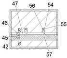
图 4 是本发明实施例图2中C处结构示意图;FIG. 4 is a schematic structural diagram of place C in FIG. 2 according to an embodiment of the present invention;
图 5 是本发明实施例图4中D-D处结构示意图。FIG. 5 is a schematic diagram of the structure at D-D in FIG. 4 according to the embodiment of the present invention.
具体实施方式Detailed ways
下面结合图1-5对本发明进行详细说明,其中,为叙述方便,现对下文所说的方位规定如下:下文所说的上下左右前后方向与图1本身投影关系的上下左右前后方向一致。The present invention will be described in detail below in conjunction with Fig. 1-5, wherein, for the convenience of description, the orientations mentioned below are now specified as follows: the up-down, left-right, front-rear directions mentioned below are consistent with the up-down, left-right, front-rear directions of the projection relationship of Fig. 1 itself.
结合附图1-5所述的一种可变换插孔角度的插座,包括机壳10,所述机壳10下端设有传动腔28,所述机壳10内上端设有控制改变插孔角度的控制机构30,所述传动腔28内设有转换插孔位置的转换机构41,所述机壳10内前端设有防尘防水功能的隔离结构23,所述控制机构30包括位于所述传动腔28后侧的从动腔32,所述从动腔32右腔壁设有开口向左的推板腔37,所述从动腔32左腔壁设有连通外界空间的伸缩孔47,所述推板腔37内设有可在腔内左右滑动的推板36,所述推板36右端面固定设有与所述推板腔37右腔壁连接的复位弹簧38,所述推板36左端面固定设有伸入所述伸缩孔47内的齿条57,所述伸缩孔47内左端设有可在腔内左右移动的推杆31,所述推杆31右端设有开口向右的滑动块45,所述滑动块45内设有可在腔内转动的滑块42,所述滑块42右端与所述齿条57左端面固定连接,所述伸缩孔47右端的腔壁内设有半圆槽58,所述推杆31右端的后端面固定设有位于所述半圆槽58内的固定块46,所述伸缩孔47右端的后腔壁设有两个开口向前的挡块腔54,所述挡块腔54内设有可在腔内前后滑动的挡块56,所述挡块56后端面固定设有与所述挡块腔54后腔壁连接的伸缩弹簧55,所述主动齿轮33后腔壁与所述传动腔28前腔壁转动连接有旋转轴34,所述旋转轴34后端设有与所述伸缩孔47上端面啮合连接的旋转齿轮35,所述旋转轴34前端设有位于所述传动腔28内的主动齿轮33。A socket with a changeable jack angle described in conjunction with the accompanying drawings 1-5 includes a
有益地,所述转换机构41包括位于所述传动腔28前腔壁内的两个相同的转杆腔48,所述传动腔28后腔壁上转动连接有分别伸入两个所述转杆腔48内的转杆43,两个转杆43后端均设有位于所述传动腔28内的不完全齿轮29,左侧的所述不完全齿轮29与所述主动齿轮33啮合连接,两个所述转杆43内均设有开口向前的接电腔24,两个所述接电腔24内均设有两块可在腔内左右移动的接电块21,左侧的所述接电块21左端面固定设有与所述接电腔24左腔壁连接的弹力弹簧25,所述接电块21后端面电连接有电线27,右侧的所述接电块21右端面固定设有与所述接电腔24右腔壁连接的所述弹力弹簧25,右侧的所述接电块21后端面电连接有导线49。Beneficially, the
有益地,所述隔离结构23包括位于所述传动腔28前侧的绳轮腔15,所述绳轮腔15前腔壁与所述传动腔28后腔壁转动连接有旋转杆40,所述旋转杆40后端设有与所述主动齿轮33和右侧的所述不完全齿轮29啮合连接的中间齿轮39,所述旋转杆40前端摩擦设有位于所述绳轮腔15内第一卷绳轮12,所述第一卷绳轮12上缠绕设有第一弹性绳18,所述旋转杆40前端还设有位于所述第一卷绳轮12前侧的第二卷绳轮13,所述第二卷绳轮13上缠绕设有第二弹性绳11,两个所述转杆腔48前腔壁均设有隔板腔22,两个所述隔板腔22的前腔壁均设有一个连通外界空间的插座孔20,两个所述隔板腔22内均设有可在腔内左右滑动的隔板19,左侧的所述隔板19右端面和右侧的所述隔板19左端面固定设有分别与两个所述隔板腔22腔壁连接的弹性弹簧17,左侧的所述隔板19右端面还连接有所述第一弹性绳18一端,右侧的所述隔板19左端面还连接有所述第二弹性绳11一端。Beneficially, the
有益地,所述弹性弹簧17的弹力大于所述隔板19在所述隔板腔22内滑动时受到的摩擦力。Beneficially, the elastic force of the elastic spring 17 is greater than the frictional force that the baffle 19 receives when sliding in the
有益地,所述复位弹簧38的弹力大于所述推杆31和所述齿条57在所述伸缩孔47内滑动时的受到的摩擦力。Beneficially, the elastic force of the
初始状态下,所述推杆31和所述齿条57在所述复位弹簧38的弹力作用下位于所述伸缩孔47的左端,所述弹性弹簧17处于压缩状态,两个所述隔板19分别在所述第一弹性绳18和第二弹性绳11的拉力作用将所述插座孔20与所述接电腔24连通。In the initial state, the
插座闲置需要防水防尘时,手动向右推动推杆31,直至推杆31无法继续向右运动,推杆31向右运动带动固定块46向右运动运动至右侧的挡块56右侧,固定块46从而被挡块56阻挡不能向左运动,推杆31向右运动带动齿条57向右运动,从而带动与齿条57啮合连接的旋转齿轮35转动,从而带动旋转轴34转动,从而带动中间齿轮39以及旋转杆40转动,从而带动旋转杆40上的第一卷绳轮12和第二卷绳轮13转动,从而将第一弹性绳18和第二弹性绳11放松,两个隔板19分别在两个所述弹性弹簧17的弹力作用下将插座孔20和接电腔24隔开,从而达到防水防尘的功能;When the socket is idle and needs to be waterproof and dustproof, manually push the
插座需要转换插孔时,在初始位置下手动向右推动推杆31向右运动一段距离,推杆31上的固定块46运动到左侧的挡块56右侧,固定块46在左侧的挡块56的阻挡下不能向左运动,推杆31向右运动带动齿条57向右运动,从而带动与齿条57啮合连接的旋转齿轮35转动,从而带动旋转轴34和主动齿轮33转动相应的角度,主动齿轮33转动带动与之啮合连接的不完全齿轮29和中间齿轮39转动,中间齿轮39转动带动与之啮合连接的右侧的不完全齿轮29转动,两个不完全齿轮29转动带动两个转杆43转动从而带动两个接电腔24转动一定的角度,从而将适用于三脚插头的插孔转变为适用与两脚插头的插孔,此时旋转杆40转动带动第一卷绳轮12和第二卷绳轮13转动的角度不足以将第一弹性绳18和第二弹性绳11放松;When the socket needs to be converted into a jack, manually push the
复位时,手动旋转推杆31,从而带动固定块46在半圆槽58内转动,固定块46从而离开挡块56的阻挡,推杆31和齿条57在复位弹簧38的弹力作用下向左运动复位,从而通过机械传动带动转杆43复位。When resetting, manually rotate the
上述实施例只为说明本发明的技术构思及特点,其目的在于让熟悉此领域技术的人士能够了解本发明内容并加以实施,并不能以此限制本发明的保护范围。凡根据本发明精神实质所作的等效变化或修饰,都应涵盖在本发明的保护范围内。The above-mentioned embodiments are only intended to illustrate the technical concept and characteristics of the present invention, and the purpose thereof is to enable those skilled in the art to understand the content of the present invention and implement it, but not to limit the protection scope of the present invention. All equivalent changes or modifications made according to the spirit of the present invention should be covered within the protection scope of the present invention.
Claims (5)
Translated fromChinesePriority Applications (1)
| Application Number | Priority Date | Filing Date | Title |
|---|---|---|---|
| CN201911137613.9ACN110797696B (en) | 2019-11-19 | 2019-11-19 | Socket capable of changing angle of jack |
Applications Claiming Priority (1)
| Application Number | Priority Date | Filing Date | Title |
|---|---|---|---|
| CN201911137613.9ACN110797696B (en) | 2019-11-19 | 2019-11-19 | Socket capable of changing angle of jack |
Publications (2)
| Publication Number | Publication Date |
|---|---|
| CN110797696Atrue CN110797696A (en) | 2020-02-14 |
| CN110797696B CN110797696B (en) | 2020-10-23 |
Family
ID=69445384
Family Applications (1)
| Application Number | Title | Priority Date | Filing Date |
|---|---|---|---|
| CN201911137613.9AActiveCN110797696B (en) | 2019-11-19 | 2019-11-19 | Socket capable of changing angle of jack |
Country Status (1)
| Country | Link |
|---|---|
| CN (1) | CN110797696B (en) |
Citations (8)
| Publication number | Priority date | Publication date | Assignee | Title |
|---|---|---|---|---|
| CN2226805Y (en)* | 1995-05-31 | 1996-05-08 | 郭伟 | Dual-purpose socket capable of regulating angle of plug jack |
| US20100068949A1 (en)* | 2004-10-13 | 2010-03-18 | Covidien Ag | Universal Foot Switch Contact Port |
| CN203242840U (en)* | 2013-04-24 | 2013-10-16 | 谢晓明 | A secure socket used for protecting plugs |
| WO2015076730A1 (en)* | 2013-11-20 | 2015-05-28 | Eazyplug Ab | Electric plug |
| CN208272311U (en)* | 2018-04-08 | 2018-12-21 | 泸州拓力源塑胶制品有限公司 | Power outlet |
| CN109119801A (en)* | 2018-09-07 | 2019-01-01 | 李成锦 | A kind of waterproof plug wire plate convenient for cable holder |
| CN109994878A (en)* | 2017-12-29 | 2019-07-09 | 四川大学华西第二医院 | Closed plug connector |
| CN110380265A (en)* | 2019-08-09 | 2019-10-25 | 中电建宁夏工程有限公司 | A kind of high security protection against electric shock plate |
- 2019
- 2019-11-19CNCN201911137613.9Apatent/CN110797696B/enactiveActive
Patent Citations (8)
| Publication number | Priority date | Publication date | Assignee | Title |
|---|---|---|---|---|
| CN2226805Y (en)* | 1995-05-31 | 1996-05-08 | 郭伟 | Dual-purpose socket capable of regulating angle of plug jack |
| US20100068949A1 (en)* | 2004-10-13 | 2010-03-18 | Covidien Ag | Universal Foot Switch Contact Port |
| CN203242840U (en)* | 2013-04-24 | 2013-10-16 | 谢晓明 | A secure socket used for protecting plugs |
| WO2015076730A1 (en)* | 2013-11-20 | 2015-05-28 | Eazyplug Ab | Electric plug |
| CN109994878A (en)* | 2017-12-29 | 2019-07-09 | 四川大学华西第二医院 | Closed plug connector |
| CN208272311U (en)* | 2018-04-08 | 2018-12-21 | 泸州拓力源塑胶制品有限公司 | Power outlet |
| CN109119801A (en)* | 2018-09-07 | 2019-01-01 | 李成锦 | A kind of waterproof plug wire plate convenient for cable holder |
| CN110380265A (en)* | 2019-08-09 | 2019-10-25 | 中电建宁夏工程有限公司 | A kind of high security protection against electric shock plate |
Also Published As
| Publication number | Publication date |
|---|---|
| CN110797696B (en) | 2020-10-23 |
Similar Documents
| Publication | Publication Date | Title |
|---|---|---|
| CN112103005B (en) | Communication cable | |
| CN111883965A (en) | Socket capable of preventing electric shock, plug falling and power-off protection | |
| CN111384616B (en) | A switchable patch panel | |
| CN110797696B (en) | Socket capable of changing angle of jack | |
| CN110011148B (en) | Data transmission line switching interface | |
| CN114421209B (en) | Push-pull type bidirectional signal quick switching connecting device | |
| CN110957674A (en) | A kind of fast bundling equipment for long-distance transmission lines | |
| CN210604764U (en) | Optical fiber current sensor with double heat dissipation structure | |
| CN111199845B (en) | Multi-contact electric switch | |
| CN115173518A (en) | Multi-component charger with high practicability | |
| CN112051421B (en) | But block terminal of self-checking electric leakage | |
| CN114050458B (en) | A conversion plug | |
| CN110911184B (en) | But remote control safety electric switch | |
| CN204632693U (en) | Double pawl planetary gear unit for electric operating mechanism | |
| CN110417183A (en) | Intelligent opening and closing curtain motor | |
| CN208723228U (en) | A kind of anti-child, which gets an electric shock, fixes lid with socket | |
| CN209511094U (en) | Electric vehicle gearshift | |
| CN110571566B (en) | Socket with changeable number of jacks | |
| CN111795140A (en) | Integrated multi-function power shift mechanism | |
| CN219801371U (en) | Cable cover for cable interface | |
| CN110783760A (en) | Can accomodate waterproof plug of power cord | |
| CN104821260A (en) | Dual pawl planetary gear device for electro-control mechanism | |
| CN216044132U (en) | Planetary gear type speed reduction starter | |
| CN112309749A (en) | Array four-in-one point-voltage electric switch | |
| CN116231213A (en) | Battery pack and shell assembly for battery pack |
Legal Events
| Date | Code | Title | Description |
|---|---|---|---|
| PB01 | Publication | ||
| PB01 | Publication | ||
| SE01 | Entry into force of request for substantive examination | ||
| SE01 | Entry into force of request for substantive examination | ||
| GR01 | Patent grant | ||
| GR01 | Patent grant | ||
| TR01 | Transfer of patent right | ||
| TR01 | Transfer of patent right | Effective date of registration:20221208 Address after:253000 East of 254 Provincial Road, North North Street, Economic Development Zone, Wucheng County, Dezhou City, Shandong Province Patentee after:Dezhou Shuanghang Packaging Products Co.,Ltd. Address before:312000 Floor 1, 15 Xiasha Road, Huatang Village, Jinting Town, Shengzhou City, Shaoxing City, Zhejiang Province Patentee before:Shengzhou Huijie Household Products Co.,Ltd. | |
| TR01 | Transfer of patent right | ||
| TR01 | Transfer of patent right | Effective date of registration:20250617 Address after:537600 Guangxi Zhuang Autonomous Region Yulin City Bobaixian County Shuangwang Town Bangjie Village Hechang Queue 011 Hao Patentee after:Guan Xian Country or region after:China Address before:253000 East of 254 Provincial Road, North North Street, Economic Development Zone, Wucheng County, Dezhou City, Shandong Province Patentee before:Dezhou Shuanghang Packaging Products Co.,Ltd. Country or region before:China |