CN110783390B - Display panel and display device - Google Patents
Display panel and display deviceDownload PDFInfo
- Publication number
- CN110783390B CN110783390BCN201911055982.3ACN201911055982ACN110783390BCN 110783390 BCN110783390 BCN 110783390BCN 201911055982 ACN201911055982 ACN 201911055982ACN 110783390 BCN110783390 BCN 110783390B
- Authority
- CN
- China
- Prior art keywords
- transparent
- area
- light
- display panel
- display
- Prior art date
- Legal status (The legal status is an assumption and is not a legal conclusion. Google has not performed a legal analysis and makes no representation as to the accuracy of the status listed.)
- Active
Links
- 239000010410layerSubstances0.000claimsdescription23
- 239000000758substrateSubstances0.000claimsdescription18
- 239000002346layers by functionSubstances0.000claimsdescription12
- 239000003086colorantSubstances0.000claimsdescription6
- 238000001914filtrationMethods0.000claims1
- 238000003384imaging methodMethods0.000abstractdescription20
- 238000010586diagramMethods0.000description19
- 230000000875corresponding effectEffects0.000description13
- 230000003313weakening effectEffects0.000description6
- 230000009286beneficial effectEffects0.000description5
- 238000005728strengtheningMethods0.000description4
- 230000000739chaotic effectEffects0.000description3
- 230000000694effectsEffects0.000description3
- 238000005516engineering processMethods0.000description3
- 239000000463materialSubstances0.000description3
- 238000000034methodMethods0.000description3
- 238000012986modificationMethods0.000description3
- 230000004048modificationEffects0.000description3
- 239000004642PolyimideSubstances0.000description2
- 239000012790adhesive layerSubstances0.000description2
- 230000001427coherent effectEffects0.000description2
- 230000002596correlated effectEffects0.000description2
- 238000005538encapsulationMethods0.000description2
- 229920001721polyimidePolymers0.000description2
- QVGXLLKOCUKJST-UHFFFAOYSA-Natomic oxygenChemical compound[O]QVGXLLKOCUKJST-UHFFFAOYSA-N0.000description1
- 239000002184metalSubstances0.000description1
- 230000003287optical effectEffects0.000description1
- 229910052760oxygenInorganic materials0.000description1
- 239000001301oxygenSubstances0.000description1
- 238000002834transmittanceMethods0.000description1
- XLYOFNOQVPJJNP-UHFFFAOYSA-NwaterChemical compoundOXLYOFNOQVPJJNP-UHFFFAOYSA-N0.000description1
Images


Classifications
- H—ELECTRICITY
- H10—SEMICONDUCTOR DEVICES; ELECTRIC SOLID-STATE DEVICES NOT OTHERWISE PROVIDED FOR
- H10K—ORGANIC ELECTRIC SOLID-STATE DEVICES
- H10K59/00—Integrated devices, or assemblies of multiple devices, comprising at least one organic light-emitting element covered by group H10K50/00
- H10K59/10—OLED displays
- H10K59/12—Active-matrix OLED [AMOLED] displays
- H10K59/121—Active-matrix OLED [AMOLED] displays characterised by the geometry or disposition of pixel elements
- G—PHYSICS
- G09—EDUCATION; CRYPTOGRAPHY; DISPLAY; ADVERTISING; SEALS
- G09F—DISPLAYING; ADVERTISING; SIGNS; LABELS OR NAME-PLATES; SEALS
- G09F9/00—Indicating arrangements for variable information in which the information is built-up on a support by selection or combination of individual elements
- G09F9/30—Indicating arrangements for variable information in which the information is built-up on a support by selection or combination of individual elements in which the desired character or characters are formed by combining individual elements
- G09F9/33—Indicating arrangements for variable information in which the information is built-up on a support by selection or combination of individual elements in which the desired character or characters are formed by combining individual elements being semiconductor devices, e.g. diodes
- H—ELECTRICITY
- H10—SEMICONDUCTOR DEVICES; ELECTRIC SOLID-STATE DEVICES NOT OTHERWISE PROVIDED FOR
- H10K—ORGANIC ELECTRIC SOLID-STATE DEVICES
- H10K59/00—Integrated devices, or assemblies of multiple devices, comprising at least one organic light-emitting element covered by group H10K50/00
- H10K59/10—OLED displays
- H10K59/12—Active-matrix OLED [AMOLED] displays
- H—ELECTRICITY
- H10—SEMICONDUCTOR DEVICES; ELECTRIC SOLID-STATE DEVICES NOT OTHERWISE PROVIDED FOR
- H10K—ORGANIC ELECTRIC SOLID-STATE DEVICES
- H10K59/00—Integrated devices, or assemblies of multiple devices, comprising at least one organic light-emitting element covered by group H10K50/00
- H10K59/30—Devices specially adapted for multicolour light emission
- H10K59/38—Devices specially adapted for multicolour light emission comprising colour filters or colour changing media [CCM]
- H—ELECTRICITY
- H10—SEMICONDUCTOR DEVICES; ELECTRIC SOLID-STATE DEVICES NOT OTHERWISE PROVIDED FOR
- H10K—ORGANIC ELECTRIC SOLID-STATE DEVICES
- H10K59/00—Integrated devices, or assemblies of multiple devices, comprising at least one organic light-emitting element covered by group H10K50/00
- H10K59/30—Devices specially adapted for multicolour light emission
- H10K59/35—Devices specially adapted for multicolour light emission comprising red-green-blue [RGB] subpixels
- H10K59/352—Devices specially adapted for multicolour light emission comprising red-green-blue [RGB] subpixels the areas of the RGB subpixels being different
- H—ELECTRICITY
- H10—SEMICONDUCTOR DEVICES; ELECTRIC SOLID-STATE DEVICES NOT OTHERWISE PROVIDED FOR
- H10K—ORGANIC ELECTRIC SOLID-STATE DEVICES
- H10K59/00—Integrated devices, or assemblies of multiple devices, comprising at least one organic light-emitting element covered by group H10K50/00
- H10K59/30—Devices specially adapted for multicolour light emission
- H10K59/35—Devices specially adapted for multicolour light emission comprising red-green-blue [RGB] subpixels
- H10K59/353—Devices specially adapted for multicolour light emission comprising red-green-blue [RGB] subpixels characterised by the geometrical arrangement of the RGB subpixels
- H—ELECTRICITY
- H10—SEMICONDUCTOR DEVICES; ELECTRIC SOLID-STATE DEVICES NOT OTHERWISE PROVIDED FOR
- H10K—ORGANIC ELECTRIC SOLID-STATE DEVICES
- H10K59/00—Integrated devices, or assemblies of multiple devices, comprising at least one organic light-emitting element covered by group H10K50/00
- H10K59/60—OLEDs integrated with inorganic light-sensitive elements, e.g. with inorganic solar cells or inorganic photodiodes
- H10K59/65—OLEDs integrated with inorganic image sensors
Landscapes
- Engineering & Computer Science (AREA)
- Physics & Mathematics (AREA)
- Microelectronics & Electronic Packaging (AREA)
- Geometry (AREA)
- General Physics & Mathematics (AREA)
- Theoretical Computer Science (AREA)
- Devices For Indicating Variable Information By Combining Individual Elements (AREA)
- Electroluminescent Light Sources (AREA)
Abstract
Description
Translated fromChinese技术领域technical field
本发明涉及显示技术领域,尤指一种显示面板及显示装置。The invention relates to the field of display technology, in particular to a display panel and a display device.
背景技术Background technique
随着显示技术的飞速发展,显示器除了传统的信息展示等作用外,在外形上的要求也在逐步提升,更大屏占比是未来市场的趋势,因而具有屏下摄像头结构的显示装置备受消费者青睐。With the rapid development of display technology, in addition to the traditional information display and other functions of the display, the requirements for appearance are also gradually increasing. The larger screen ratio is the trend of the future market, so the display device with the camera structure under the screen is highly sought after. Consumers favor.
在具有屏下摄像头结构的显示装置中,摄像头设置于显示面板的显示区域下方,光线可穿过显示面板的显示区域射向摄像头,以使摄像头拍摄到画面,然而,由于衍射现象的存在,使得摄像头的成像质量较差,摄像头拍摄的画面比较模糊。In a display device with an under-screen camera structure, the camera is arranged below the display area of the display panel, and the light can pass through the display area of the display panel to the camera, so that the camera can capture pictures. However, due to the existence of diffraction phenomenon, the The imaging quality of the camera is poor, and the pictures taken by the camera are blurry.
发明内容Contents of the invention
本发明实施例提供一种显示面板及显示装置,用以缓解现有技术中存在的由于衍射现象的存在导致的摄像头的成像质量较差的问题。Embodiments of the present invention provide a display panel and a display device, which are used to alleviate the problem of poor imaging quality of a camera due to the existence of diffraction phenomena existing in the prior art.
第一方面,本发明实施例提供了一种显示面板,所述显示面板的显示区域分为相连接的常规显示区域和透明显示区域;其中,In the first aspect, an embodiment of the present invention provides a display panel, where the display area of the display panel is divided into a connected conventional display area and a transparent display area; wherein,
所述透明显示区域包括多个透明区域和多个像素;The transparent display area includes a plurality of transparent areas and a plurality of pixels;
各所述透明区域的形状相同,对于相邻的两个透明区域,其中一个透明区域的形状的摆放角度与另一个透明区域的形状的摆放角度不同。The shapes of each of the transparent areas are the same, and for two adjacent transparent areas, the arrangement angle of the shape of one transparent area is different from that of the other transparent area.
第二方面,本发明实施例还提供了一种显示装置,包括上述显示面板。In a second aspect, an embodiment of the present invention further provides a display device, including the above-mentioned display panel.
本发明有益效果如下:The beneficial effects of the present invention are as follows:
本发明实施例提供的显示面板及显示装置,显示面板的显示区域分为相连接的常规显示区域和透明显示区域;其中,透明显示区域包括多个透明区域和多个像素;各透明区域的形状相同,对于相邻的两个透明区域,其中一个透明区域的形状的摆放角度与另一个透明区域的形状的摆放角度不同。本发明实施例提供的显示面板中,透明显示区域中的各透明区域的形状相同,且对于相邻的两个透明区域,其中一个透明区域的形状的摆放角度与另一个透明区域的形状的摆放角度不同,因而打破了各透明区域均匀且按照统一方向进行排列的规律,由此可以避免光线经过透明区域后,由于干涉和衍射的作用在摄像头的特定区域产生加强或减弱的现象,从而提高摄像头的成像质量,使摄像头拍摄的画面比较清晰。In the display panel and the display device provided by the embodiments of the present invention, the display area of the display panel is divided into a connected conventional display area and a transparent display area; wherein, the transparent display area includes a plurality of transparent areas and a plurality of pixels; the shape of each transparent area Similarly, for two adjacent transparent areas, the arrangement angle of the shape of one transparent area is different from that of the other transparent area. In the display panel provided by the embodiment of the present invention, the shapes of the transparent regions in the transparent display region are the same, and for two adjacent transparent regions, the arrangement angle of the shape of one transparent region is different from that of the shape of the other transparent region. The placement angles are different, which breaks the law that the transparent areas are uniform and arranged in a uniform direction, thereby avoiding the phenomenon of strengthening or weakening in a specific area of the camera due to interference and diffraction after the light passes through the transparent area, thereby Improve the imaging quality of the camera, so that the pictures taken by the camera are clearer.
附图说明Description of drawings
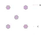
图1为现有技术中具有屏下摄像头结构的显示装置中的俯视结构示意图;FIG. 1 is a schematic top view of a display device with an under-screen camera structure in the prior art;
图2为对应于图1的结构的成像原理示意图;Fig. 2 is a schematic diagram of the imaging principle corresponding to the structure of Fig. 1;
图3为光线穿过图1所示的显示装置中的透明区域后的亮度分布示意图;FIG. 3 is a schematic diagram of brightness distribution after light passes through a transparent region in the display device shown in FIG. 1;
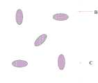
图4为本发明实施例中显示面板的俯视结构示意图;FIG. 4 is a schematic top view of a display panel in an embodiment of the present invention;
图5为本发明实施例中显示区域的具体结构示意图;FIG. 5 is a schematic diagram of a specific structure of a display area in an embodiment of the present invention;
图6为判断两个透明区域的摆放角度是否相同的过程示意图;Fig. 6 is a schematic diagram of the process of judging whether the placement angles of two transparent areas are the same;
图7为本发明实施例中透明显示区域中透明区域的分布示意图;7 is a schematic diagram of the distribution of transparent areas in the transparent display area in the embodiment of the present invention;
图8为光线穿过图7所示的显示面板中的透明区域后的亮度分布示意图;FIG. 8 is a schematic diagram of brightness distribution after light passes through the transparent area in the display panel shown in FIG. 7;
图9和图10为不同形状的透明区域的排布示意图;Figure 9 and Figure 10 are schematic diagrams of the arrangement of transparent regions of different shapes;
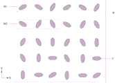
图11为本发明实施例提供的透明显示区域中透明区域的排布示意图之一;Fig. 11 is one of the schematic diagrams of the arrangement of the transparent areas in the transparent display area provided by the embodiment of the present invention;
图12为本发明实施例提供的透明显示区域中透明区域的排布示意图之二;Fig. 12 is the second schematic diagram of the arrangement of the transparent area in the transparent display area provided by the embodiment of the present invention;
图13为本发明实施例提供的透明显示区域中透明区域的排布示意图之三;Fig. 13 is the third schematic diagram of the arrangement of the transparent area in the transparent display area provided by the embodiment of the present invention;
图14为本发明实施例提供的透明显示区域中透明区域的排布示意图之四;FIG. 14 is the fourth schematic diagram of the arrangement of transparent areas in the transparent display area provided by the embodiment of the present invention;
图15为本发明实施例提供的透明显示区域中透明区域的排布示意图之五;Fig. 15 is the fifth schematic diagram of the arrangement of the transparent area in the transparent display area provided by the embodiment of the present invention;
图16为本发明实施例提供的透明显示区域中透明区域的排布示意图之六;FIG. 16 is the sixth schematic diagram of the arrangement of transparent areas in the transparent display area provided by the embodiment of the present invention;
图17为本发明实施例提供的透明显示区域中透明区域的排布示意图之七;Fig. 17 is the seventh schematic diagram of the arrangement of transparent areas in the transparent display area provided by the embodiment of the present invention;
图18为从遮光层朝向衬底基板的方向观看显示面板的俯视结构示意图;18 is a schematic top view of the display panel viewed from the direction of the light-shielding layer towards the base substrate;
图19为图18中虚线W处的截面示意图;Fig. 19 is a schematic cross-sectional view at the dotted line W in Fig. 18;
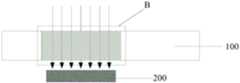
图20为本发明实施例中显示面板的截面示意图;20 is a schematic cross-sectional view of a display panel in an embodiment of the present invention;
图21为本发明实施例中显示面板的截面示意图;21 is a schematic cross-sectional view of a display panel in an embodiment of the present invention;
图22为本发明实施例提供的显示装置的俯视结构示意图;FIG. 22 is a schematic top view of a display device provided by an embodiment of the present invention;
图23为图22中虚线S处的截面示意图。FIG. 23 is a schematic cross-sectional view at the dotted line S in FIG. 22 .
具体实施方式Detailed ways
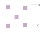
图1为现有技术中具有屏下摄像头结构的显示装置中的俯视结构示意图,FIG. 1 is a schematic top view of a display device with an under-screen camera structure in the prior art,
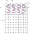
图2为对应于图1的结构的成像原理示意图,如图1所示,该显示装置的透明显示区域B中包括多个规则排列的透明区域C,图中仅有限数量的透明区域C进行示意。图2中的上半部分为显示装置的局部俯视图,图2中的下半部分为与该俯视图相应的剖面图。Fig. 2 is a schematic diagram of the imaging principle corresponding to the structure in Fig. 1. As shown in Fig. 1, the transparent display area B of the display device includes a plurality of regularly arranged transparent areas C, and only a limited number of transparent areas C are shown in the figure . The upper half in FIG. 2 is a partial top view of the display device, and the lower half in FIG. 2 is a cross-sectional view corresponding to the top view.
如图2所示,光线穿过显示面板射向摄像头200,光线在传播过程中会在第一电极111的边缘处发生衍射,使平行入射的光线(如图2中平行向下的箭头所示)在第一电极111的边缘处形成发散的衍射光,如图2中,在第一电极111的边缘a、b、c和d处形成了发散光,如图中a、b、c和d处的箭头所示。As shown in FIG. 2 , the light passes through the display panel and shoots towards the
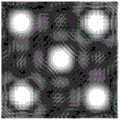
图3为光线穿过图1所示的显示装置中的透明区域后的亮度分布示意图,由于透明显示区域B中的多个透明区域C规则排列,光线经过各透明区域C后形成的衍射光会在特定区域产生相干加强或减弱现象,图3中五个较亮的区域为光线的中心区域,中心区域对应于显示面板中的透明区域,图中每一个中心区域周围都存在四个衍射加强区,该衍射加强区就是由于衍射光在该区域产生相干加强产生的,因而会使中心区域与衍射加强区之间的对比度较小,衍射加强区的衍射图案对中心区域的光信息形成干扰,导致摄像头200接收叠加了衍射光的光线后,会在特定区域形成相应的条纹,从而影响摄像头200的成像质量,使摄像头拍摄的画面比较模糊。Fig. 3 is a schematic diagram of the luminance distribution after the light passes through the transparent regions in the display device shown in Fig. 1. Since the plurality of transparent regions C in the transparent display region B are arranged regularly, the diffracted light formed after the light passes through the transparent regions C will be The phenomenon of coherent enhancement or weakening occurs in a specific area. The five brighter areas in Figure 3 are the central areas of the light, and the central area corresponds to the transparent area in the display panel. There are four diffraction enhanced areas around each central area in the figure. , the diffraction-intensified area is produced by the coherence enhancement of diffracted light in this area, so the contrast between the central area and the diffraction-intensified area will be small, and the diffraction pattern in the diffraction-intensified area will interfere with the optical information in the central area, resulting in After the
基于此,针对现有技术中存在的由于衍射现象的存在导致的摄像头的成像质量较差的问题,本发明实施例提供了一种显示面板及显示装置。Based on this, aiming at the problem in the prior art that the imaging quality of the camera is poor due to the existence of the diffraction phenomenon, the embodiments of the present invention provide a display panel and a display device.
下面结合附图,对本发明实施例提供的显示面板及显示装置的具体实施方式进行详细地说明。附图中各膜层的厚度和形状不反映真实比例,目的只是示意说明本发明内容。The specific implementation manners of the display panel and the display device provided by the embodiments of the present invention will be described in detail below with reference to the accompanying drawings. The thickness and shape of each film layer in the drawings do not reflect the real scale, and the purpose is only to illustrate the content of the present invention.
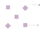
第一方面,本发明实施例提供了一种显示面板,图4为本发明实施例中显示面板的俯视结构示意图,如图4所示,显示面板的显示区域分为相连接的常规显示区域A和透明显示区域B;其中,In the first aspect, the embodiment of the present invention provides a display panel. FIG. 4 is a schematic top view of the display panel in the embodiment of the present invention. As shown in FIG. 4 , the display area of the display panel is divided into connected conventional display areas A and transparent display area B; where,
图5为本发明实施例中显示区域的具体结构示意图,如图5所示,透明显示区域B包括多个透明区域C和多个像素P;FIG. 5 is a schematic diagram of the specific structure of the display area in the embodiment of the present invention. As shown in FIG. 5, the transparent display area B includes a plurality of transparent areas C and a plurality of pixels P;
各透明区域C的形状相同,对于相邻的两个透明区域C,其中一个透明区域C的形状的摆放角度与另一个透明区域C的形状的摆放角度不同。The shapes of the transparent regions C are the same, and for two adjacent transparent regions C, the arrangement angle of the shape of one transparent region C is different from the arrangement angle of the shape of the other transparent region C.
本发明实施例提供的显示面板中,透明显示区域中的各透明区域的形状相同,且对于相邻的两个透明区域,其中一个透明区域的形状的摆放角度与另一个透明区域的形状的摆放角度不同,因而打破了各透明区域均匀且按照统一方向进行排列的规律,由此可以避免光线经过透明区域后,由于干涉和衍射的作用在摄像头的特定区域产生加强或减弱的现象,从而提高摄像头的成像质量,使摄像头拍摄的画面比较清晰。In the display panel provided by the embodiment of the present invention, the shapes of the transparent regions in the transparent display region are the same, and for two adjacent transparent regions, the arrangement angle of the shape of one transparent region is different from that of the shape of the other transparent region. The placement angles are different, which breaks the law that the transparent areas are uniform and arranged in a uniform direction, thereby avoiding the phenomenon of strengthening or weakening in a specific area of the camera due to interference and diffraction after the light passes through the transparent area, thereby Improve the imaging quality of the camera, so that the pictures taken by the camera are clearer.
如图5所示,透明显示区域B为显示区域的一部分,透明显示区域B包括多个像素P,在显示过程中,透明显示区域B可实现画面显示,并且,透明显示区域B的像素P之间的间隙中具有多个透明区域C,透明区域C可使外界光线穿过显示面板射向摄像头,以使摄像头接收到光线后成像。As shown in Figure 5, the transparent display area B is a part of the display area, and the transparent display area B includes a plurality of pixels P. During the display process, the transparent display area B can realize picture display, and the pixels P in the transparent display area B There are a plurality of transparent regions C in the gap between them, and the transparent regions C can allow external light to pass through the display panel to the camera, so that the camera can form an image after receiving the light.
在图5中,以圆圈表示像素P,并不对像素P的形状进行限定,在具体实施时,像素P可以也可以为其他形状,表示像素P的圆圈内的字母R、G、B表示该像素P的颜色,图5中仅以有限数量的像素P,和某种像素排列进行示意,并不对像素的数量和排列方式进行限定。In Fig. 5, the pixel P is represented by a circle, and the shape of the pixel P is not limited. In a specific implementation, the pixel P may also be in other shapes, and the letters R, G, and B in the circle representing the pixel P represent the pixel. The color of P is illustrated only by a limited number of pixels P and a certain arrangement of pixels in FIG. 5 , and the number and arrangement of pixels are not limited.
在本发明实施例中,透明显示区域B中的两个透明区域C形状相同,可以理解为,若两个透明区域C的摆放角度相同,则将其中一个透明区域C缩放一定倍数后,移动到另一个透明区域C的位置处,两个透明区域可以重合。In the embodiment of the present invention, the two transparent regions C in the transparent display region B have the same shape. It can be understood that, if the two transparent regions C are placed at the same angle, one of the transparent regions C will be scaled by a certain factor and then moved At the position of another transparent area C, the two transparent areas can overlap.
在本发明实施例中,对于相邻的两个透明区域C,其中一个透明区域C的形状的摆放角度与另一个透明区域C的形状的摆放角度不同,可以理解为,对于相邻的两个透明区域,其中一个透明区域C通过缩放、平移和转动后可与另一个透明区域C重合,且该透明区域C仅通过缩放和平移后不能与另一个透明区域C重合。In the embodiment of the present invention, for two adjacent transparent regions C, the arrangement angle of the shape of one transparent region C is different from that of the other transparent region C, it can be understood that for adjacent Two transparent areas, one transparent area C can coincide with the other transparent area C after zooming, translation and rotation, and the transparent area C cannot coincide with the other transparent area C only after zooming and translation.
以图5中的两个透明区域C1和C2为例,假设透明区域C1和C2的面积相同,如图6所示,将透明区域C1缩放一倍且平移至透明区域C2后,平移后的位置如虚线状的椭圆所示,从图6可明显看出,平移后的透明区域C1不能与透明区域C2重合,并且,若将图6中的虚线状的椭圆顺时针转动一定角度后,可以与透明区域C2重合,即透明区域C1通过缩放、平移和转动后可与透明区域C2重合,且透明区域C1仅通过缩放和平移不能与透明区域C重合,因而,透明区域C1和透明区域C2的摆放角度不同。Take the two transparent areas C1 and C2 in Figure 5 as an example, assuming that the areas of the transparent areas C1 and C2 are the same, as shown in Figure 6, after the transparent area C1 is doubled and translated to the transparent area C2, the position after translation As shown by the dotted ellipse, it can be clearly seen from Figure 6 that the translated transparent area C1 cannot overlap with the transparent area C2, and if the dotted ellipse in Figure 6 is rotated clockwise by a certain angle, it can be aligned with The transparent area C2 coincides, that is, the transparent area C1 can coincide with the transparent area C2 after zooming, translation and rotation, and the transparent area C1 cannot coincide with the transparent area C only through zooming and translation. Therefore, the swing between the transparent area C1 and the transparent area C2 The angles are different.
本发明实施例中,透明显示区域B中的各透明区域C的形状相同,且对于相邻的两个透明区域C,其中一个透明区域C的形状的摆放角度与另一个透明区域C的摆放角度不同,因而透明显示区域B中的各透明区域C是错乱排列的,而不是按照统一的方式规律排列,因而光线经过透明显示区域B中的各透明区域C后,不会在特定区域产生相干加强或减弱现象。In the embodiment of the present invention, the shapes of the transparent regions C in the transparent display region B are the same, and for two adjacent transparent regions C, the arrangement angle of the shape of one transparent region C is the same as that of the other transparent region C. The angles are different, so the transparent areas C in the transparent display area B are arranged randomly, rather than arranged in a uniform way, so after the light passes through the transparent areas C in the transparent display area B, it will not appear in a specific area. Coherent strengthening or weakening phenomenon.
并且,通过设置相邻两个透明区域的摆放角度不同,从而使相邻两个透明区域的相对的边之间不存在相互平行的部分,相比于相对的边相互平行的相邻两个透明区域,避免了衍射光线在特定区域产生衍射加强现象,摄像头接收到的光线中叠加的衍射光较少,或者摄像头接收到的光线中无叠加的衍射光,从而避免摄像头接收叠加衍射条纹的光图案信息,从而提高了摄像头的成像质量,使摄像头拍摄的画面更加清晰。Moreover, by setting the angles of placement of two adjacent transparent areas to be different, there is no part parallel to each other between the opposite sides of the two adjacent transparent areas. The transparent area avoids the phenomenon of enhanced diffraction of diffracted light in a specific area. There is less superimposed diffracted light in the light received by the camera, or there is no superimposed diffracted light in the light received by the camera, thereby preventing the camera from receiving light superimposed with diffraction fringes Pattern information, thereby improving the imaging quality of the camera and making the picture captured by the camera clearer.
图5中以透明区域C为椭圆形为例进行示意,在具体实施时,透明区域C也可以为其他形状,例如,透明区域C可以为如图7所示的正方形,或者,透明区域C可以为如图9所示的六边形,也可以为其他形状,此处不对透明区域C的形状进行限定。In Fig. 5, the transparent region C is an ellipse as an example for illustration. During specific implementation, the transparent region C may also be in other shapes. For example, the transparent region C may be a square as shown in Fig. 7, or the transparent region C may be It is a hexagon as shown in FIG. 9 , and may also be in other shapes, and the shape of the transparent region C is not limited here.
图7为本发明实施例中透明显示区域中透明区域的分布示意图,图7与图1中除透明区域的摆放角度不同,对应位置处的透明区域的形状、面积以及透明区域的分布均相同,图8为光线穿过图7所示的显示面板中的透明区域后的亮度分布示意图,从图8可以明显看出,相比于图3所示的亮度分布示意图,图8中的各中心区域的周围的衍射加强区的亮度明显降低,且衍射加强区的面积较小且比较分散,能够明显提高中心区域与衍射加强区的对比度,证明了本发明实施例提供的显示面板中,通过设置相邻两个透明区域的摆放角度不同,可减弱衍射光的相干加强,从而可以减少穿过显示面板的光线形成的衍射条纹,从而提高了摄像头的成像质量。Fig. 7 is a schematic diagram of the distribution of transparent areas in the transparent display area in the embodiment of the present invention. Fig. 7 is different from that in Fig. 1 except that the placement angle of the transparent areas is different, and the shape, area and distribution of the transparent areas at the corresponding positions are the same , FIG. 8 is a schematic diagram of the brightness distribution after the light passes through the transparent area in the display panel shown in FIG. 7. It can be clearly seen from FIG. The brightness of the diffraction-intensified area around the area is significantly reduced, and the area of the diffraction-enhanced area is small and scattered, which can significantly improve the contrast between the central area and the diffraction-enhanced area. It proves that in the display panel provided by the embodiment of the present invention, by setting The arrangement angles of two adjacent transparent regions are different, which can weaken the coherence enhancement of diffracted light, thereby reducing the diffraction fringes formed by the light passing through the display panel, thereby improving the imaging quality of the camera.
在具体实施时,如图6和图10所示,可将透明显示区域B设置为任意相邻两个透明区域C的摆放角度均不相同,或者,也可以设置为透明显示区域B中的一部分透明区域C,满足相邻的两个透明区域C的摆放角度不同,允许存在一些透明区域C的摆放角度相同,可以根据显示面板的具体结构进行设置,此处不做限定。In specific implementation, as shown in Figure 6 and Figure 10, the transparent display area B can be set so that the placement angles of any two adjacent transparent areas C are different, or it can also be set as the transparent display area B For a part of the transparent regions C, two adjacent transparent regions C have different placement angles, and some transparent regions C are allowed to have the same placement angle, which can be set according to the specific structure of the display panel, which is not limited here.
可选地,本发明实施提供的上述显示面板中,如图11所示,各透明区域C呈阵列排布;Optionally, in the above display panel provided by the implementation of the present invention, as shown in FIG. 11 , the transparent regions C are arranged in an array;
在行方向X或列方向Y上,对于相邻的两个透明区域C,其中一个透明区域C的形状的摆放角度与另一个透明区域C的形状的摆放角度不同。In the row direction X or the column direction Y, for two adjacent transparent regions C, the arrangement angle of the shape of one transparent region C is different from that of the other transparent region C.
将各透明区域C设置为呈阵列排布,可使射向摄像头的光线更加均匀,并且,可以使透明显示区域B中的像素排布更加均匀,保证显示面板在能够正常显示的情况下,能够使摄像头拍摄清晰的画面。Arranging each transparent area C in an array can make the light emitted to the camera more uniform, and can make the pixel arrangement in the transparent display area B more uniform, ensuring that the display panel can display normally. Make the camera take a clear picture.
本发明实施例中,可以仅在行方向上,将各透明区域设置为相邻的两个透明区域的形状的摆放角度不同,也可以仅在列方向上,将各透明区域设置为相邻的两个透明区域的形状的摆放角度不同,或者,也可以在行方向和列方向,均设置为相邻的两个透明区域的形状的摆放角度不同,此处不做限定。这样,可以使透明显示区域B中的各透明区域C的排列较杂乱,从而保证射向摄像头的衍射光较少,保证摄像头具有较好的成像质量。In the embodiment of the present invention, it is possible to set each transparent area so that the shapes of two adjacent transparent areas have different placement angles only in the row direction, or set each transparent area to be adjacent to each other only in the column direction. The placement angles of the shapes of the two transparent areas are different, or, in both the row direction and the column direction, the shapes of the two adjacent transparent areas may be arranged at different angles, which is not limited here. In this way, the arrangement of the transparent regions C in the transparent display region B can be made chaotic, thereby ensuring less diffracted light directed to the camera and ensuring better imaging quality of the camera.
进一步地,本发明实施例提供的上述显示面板中,如图12所示,在第一方向Z上,对于相邻的两个透明区域C,其中一个透明区域C的形状的摆放角度与另一个透明区域C的形状的摆放角度不同;Further, in the above-mentioned display panel provided by the embodiment of the present invention, as shown in FIG. 12 , in the first direction Z, for two adjacent transparent regions C, the arrangement angle of the shape of one transparent region C is different from that of the other. The shapes of a transparent area C are placed at different angles;
其中,第一方向Z为与行方向X和列方向Y均不同的方向。Wherein, the first direction Z is a direction different from both the row direction X and the column direction Y.
如图12所示,以第一方向Z为从左下角指向右上角的对角线为例进行示意,在第一方向Z上,将各透明区域C也设置为相邻的两个透明区域的形状的摆放角度不同,可以使透明显示区域B中的各透明区域C的排列更加杂乱,可进一步减弱射向摄像头的衍射光,从而进一步提高摄像头的成像质量。As shown in FIG. 12 , it is illustrated by taking the first direction Z as a diagonal line from the lower left corner to the upper right corner as an example. In the first direction Z, each transparent area C is also set as the distance between two adjacent transparent areas. Different placement angles of the shapes can make the arrangement of the transparent regions C in the transparent display region B more chaotic, and can further weaken the diffracted light directed to the camera, thereby further improving the imaging quality of the camera.
可选地,本发明实施提供的上述显示面板中,如图13所示,在透明显示区域B内,各透明区域C的形状的摆放角度均不同。Optionally, in the above-mentioned display panel provided by the implementation of the present invention, as shown in FIG. 13 , in the transparent display area B, the shapes and placement angles of the transparent areas C are different.
如图13所示,在透明显示区域B内,任意两个透明区域C的形状的摆放角度均不相同,因而,穿过各透明区域C的光线不容易发生衍射,可进一步提高摄像头的成像质量。As shown in Figure 13, in the transparent display area B, the placement angles of the shapes of any two transparent areas C are different. Therefore, the light passing through each transparent area C is not easy to diffract, which can further improve the imaging of the camera. quality.
在实际应用中,本发明实施例提供的上述显示面板中,如图14所示,位于同一行X的透明区域C被划分为多个重复单元,如图14中第一行的透明区域C被划分为多个重复单元M1,第二行的透明区域C被划分为多个重复单元M2,重复单元包括至少两个透明区域C,且属于同一个重复单元的各透明区域C的形状的摆放角度互不相同,例如重复单元M1中的三个透明区域C的形状的摆放角度互不相同,重复单元M2中的三个透明区域C的形状的摆放角度互不相同;图14中以各行重复单元包含的透明区域C的个数相同为例,在具体实施时,位于不同行的重复单元中的透明区域C的个数也可以为不同,此处不做限定。In practical applications, in the above-mentioned display panel provided by the embodiment of the present invention, as shown in FIG. 14 , the transparent area C located in the same row X is divided into multiple repeating units. Divided into multiple repeating units M1, the transparent area C in the second row is divided into multiple repeating units M2, the repeating unit includes at least two transparent areas C, and the shape of each transparent area C belonging to the same repeating unit is arranged The angles are different from each other. For example, the placement angles of the shapes of the three transparent regions C in the repeating unit M1 are different from each other, and the placement angles of the shapes of the three transparent regions C in the repeating unit M2 are different from each other; The number of transparent regions C included in the repeating units of each row is the same as an example. In actual implementation, the number of transparent regions C in the repeating units of different rows may also be different, which is not limited here.
或,or,
如图15所示,位于同一列Y的透明区域C被划分为多个重复单元,如图15中第一列的透明区域C被划分为多个重复单元N1,第二列的透明区域C被划分为多个重复单元N2,重复单元包括至少两个透明区域C,且属于同一个重复单元的各透明区域C的形状的摆放角度互不相同,例如重复单元N1中的三个透明区域C的形状的摆放角度互不相同,重复单元N2中的三个透明区域C的形状的摆放角度互不相同;图15中以各列重复单元包含的透明区域C的个数相同为例,在具体实施时,位于不同列的重复单元中的透明区域C的个数也可以为不同,此处不做限定。As shown in Figure 15, the transparent area C in the same column Y is divided into multiple repeating units, as shown in Figure 15, the transparent area C in the first column is divided into multiple repeating units N1, and the transparent area C in the second column is divided into Divided into a plurality of repeating units N2, the repeating unit includes at least two transparent regions C, and the shapes of the transparent regions C belonging to the same repeating unit are placed at different angles, for example, the three transparent regions C in the repeating unit N1 The placement angles of the shapes are different from each other, and the placement angles of the shapes of the three transparent regions C in the repeating unit N2 are different from each other; in Figure 15, the number of transparent regions C contained in each row of repeating units is the same as an example, During specific implementation, the number of transparent regions C in repeating units in different columns may also be different, which is not limited here.
或,or,
如图16所示,位于同一行X的透明区域C被划分为多个重复单元,例如,第一行的透明区域C被划分为多个重复单元M1,第二行的透明区域C被划分为多个重复单元M2,位于同一列Y的透明区域C被划分为多个重复单元,重复单元包括至少两个透明区域C,例如,第一列的透明区域C被划分为多个重复单元N1,第二列的透明区域C被划分为多个重复单元N2,且属于同一个重复单元的各透明区域C的形状的摆放角度互不相同,如图16中,以各重复单元包含的透明区域C的个数相同为例,在具体实施时,位于不同的重复单元中的透明区域C的个数也可以为不同,此处不做限定。As shown in Figure 16, the transparent area C located in the same row X is divided into multiple repeating units, for example, the transparent area C in the first row is divided into multiple repeating units M1, and the transparent area C in the second row is divided into A plurality of repeating units M2, the transparent area C located in the same column Y is divided into a plurality of repeating units, the repeating unit includes at least two transparent areas C, for example, the transparent area C of the first column is divided into a plurality of repeating units N1, The transparent area C in the second column is divided into multiple repeating units N2, and the shapes of the transparent areas C belonging to the same repeating unit are placed at different angles. As shown in Figure 16, the transparent areas contained in each repeating unit The number of C is the same as an example, and in actual implementation, the number of transparent regions C located in different repeating units may also be different, which is not limited here.
图14至图16中以每个重复单元包括三个透明区域C进行示意,并不对重复单元中透明区域的数量进行限定。14 to 16 illustrate that each repeating unit includes three transparent regions C, and the number of transparent regions C in the repeating unit is not limited.
将透明显示区域B中的各透明区域C设置为,在行方向X和/或列方向Y上划分为多个重复单元,且属于同一个重复单元的各透明区域的C形状的摆放角度不同,从而可以使相邻的多个透明区域C之间的摆放角度不同,使透明显示区域B中的各透明区域C比较杂乱,从而使光线穿过各透明区域C后不容易发生衍射,从而提高摄像头的成像质量。Each transparent area C in the transparent display area B is set to be divided into multiple repeating units in the row direction X and/or column direction Y, and the placement angles of the C shapes of the transparent areas belonging to the same repeating unit are different , so that the placement angles between a plurality of adjacent transparent regions C can be different, so that the transparent regions C in the transparent display region B are relatively chaotic, so that light rays are not easily diffracted after passing through the transparent regions C, thus Improve the image quality of the camera.
应该说明的是,图11至图16以透明区域C为椭圆形为例进行举例,对于其他形状的透明区域C,也可以进行相应的设置,此处不再一一举例。It should be noted that FIGS. 11 to 16 take the transparent region C as an example in an ellipse shape. For transparent regions C of other shapes, corresponding settings can also be made, and no more examples will be given here.
具体地,本发明实施例提供的上述显示面板中,如图11所示,各透明区域C呈阵列排布;Specifically, in the above display panel provided by the embodiment of the present invention, as shown in FIG. 11 , the transparent regions C are arranged in an array;
位于同一行X的各透明区域C的几何中心等间距设置;和/或,The geometric centers of the transparent regions C located in the same row X are set at equal intervals; and/or,
位于同一列Y的各透明区域C的几何中心等间距设置。The geometric centers of the transparent regions C located in the same column Y are set at equal intervals.
这样,可使透过各透明区域C的光线更加均匀,使摄像头接收到的光线强度比较均匀,从而保证能够得到较为清晰的画面,并且,将各透明区域C设置为在行方向X和/或列方向Y上几何中心等间距设置,也可以使透明显示区域B中的像素排布更加均匀,保证透明显示区域可以正常显示画面。In this way, the light passing through each transparent area C can be made more uniform, so that the light intensity received by the camera is relatively uniform, thereby ensuring a clearer picture, and each transparent area C is set to be in the row direction X and/or The equidistant arrangement of the geometric centers in the column direction Y can also make the arrangement of pixels in the transparent display area B more uniform, and ensure that the transparent display area can display images normally.
在具体实施时,本发明实施例提供的上述显示面板中,各透明区域的面积相同,从而使各透明区域能够透过的光线总量大致相同,以使摄像头接收到的光线强度较为均一,进一步提高摄像头的成像质量。In specific implementation, in the above-mentioned display panel provided by the embodiment of the present invention, the areas of the transparent regions are the same, so that the total amount of light that can pass through the transparent regions is approximately the same, so that the light intensity received by the camera is relatively uniform, and further Improve the image quality of the camera.
在实际应用中,本发明实施例提供的上述显示面板中,如图17所示,透明区域C的形状为轴对称形状,形状包括多个对称轴,图17以透明区域C的形状为正方形为例,以图17中第一行第一个透明区域C为例,该透明区域C具有四条对称轴,如图中虚线所示,在形状的各对称轴中,各相邻两个对称轴之间的夹角中的最小夹角为第一角度,即图中的角θ1;In practical applications, in the above-mentioned display panel provided by the embodiment of the present invention, as shown in FIG. 17 , the shape of the transparent region C is an axisymmetric shape, and the shape includes multiple symmetry axes. In FIG. 17 , the shape of the transparent region C is a square. For example, take the first transparent area C in the first row in Figure 17 as an example. This transparent area C has four symmetry axes, as shown by the dotted lines in the figure. The minimum included angle among the included angles is the first angle, that is, the angle θ1 in the figure;
对于相邻的两个透明区域C,如图17中第一行中的两个透明区域C,将其中一个透明区域C的形状转动第二角度θ2后得到的形状的摆放角度与另一个透明区域C的形状的摆放角度相同;For two adjacent transparent regions C, such as the two transparent regions C in the first row in Figure 17, the shape of one of the transparent regions C is rotated by the second angle θ2 to obtain the shape placement angle that is the same as that of the other transparent region C The placement angles of the shapes of area C are the same;
第二角度小于第一角度。The second angle is smaller than the first angle.
以第一行第一个透明区域C的对称轴L1为参考线,将第一行第一个透明区域C顺时针转动第二角度θ2后,得到的形状与第一行第二个透明区域C的摆放角度相同,第一行第二个透明区域C对应于参考线的对称轴为L2,将L1平移至第一行第二个透明区域C处,L1与L2的夹角即为第二角度θ2。Taking the symmetry axis L1 of the first transparent area C in the first row as a reference line, after turning the first transparent area C in the first row clockwise by a second angle θ2, the obtained shape is the same as that of the second transparent area C in the first row The placement angles are the same, the symmetry axis of the second transparent area C in the first row corresponding to the reference line is L2, and when L1 is translated to the second transparent area C in the first row, the angle between L1 and L2 is the second Angle θ2.
对于相邻的两个透明区域C,将其中一个透明区域C转动第二角度θ2后得到的形状的摆放角度与另一个透明区域C的形状的摆放角度相同,由于第二角度θ2小于第一角度θ1,因而将透明区域C转动第二角度θ2后得到的形状的摆放角度必然不同于原来的形状。For two adjacent transparent regions C, the arrangement angle of the shape obtained by rotating one of the transparent regions C by the second angle θ2 is the same as the arrangement angle of the shape of the other transparent region C, because the second angle θ2 is smaller than the first Therefore, the arrangement angle of the shape obtained by rotating the transparent region C by the second angle θ2 must be different from the original shape.
在具体实施时,可以将透明显示区域中的各透明区域设置为:在行方向、列方向或第一方向上的第i+1个透明区域为第i个透明区域顺时针(或逆时针)转动第二角度得到,第一方向为不同于行方向和列方向的方向。In specific implementation, each transparent area in the transparent display area can be set as follows: the i+1th transparent area in the row direction, column direction or first direction is the i-th transparent area clockwise (or counterclockwise) Rotating the second angle results in that the first direction is a direction different from the row direction and the column direction.
具体地,本发明实施例提供的上述显示面板中,上述透明区域的形状可以为多边形,例如上述透明区域可以为正方形、五边形、六边形等形状。Specifically, in the above-mentioned display panel provided by the embodiment of the present invention, the shape of the above-mentioned transparent area may be a polygon, for example, the above-mentioned transparent area may be in the shape of a square, a pentagon, or a hexagon.
由于透明区域的边越多,射向透明区域的边缘处的光线越不容易发生相干加强或减弱现象,因而透明区域的边越多,摄像头接收到的光线中叠加的衍射光就越少,更有利于提高摄像头的成像质量。Since the more sides of the transparent area, the less likely the coherence enhancement or weakening will occur to the light rays hitting the edge of the transparent area, so the more sides of the transparent area, the less diffracted light superimposed in the light received by the camera, and more It is beneficial to improve the imaging quality of the camera.
可选地,本发明实施例提供的上述显示面板中,上述形状的边包括弧线。Optionally, in the above display panel provided by the embodiment of the present invention, the sides of the above shape include arcs.
由于透明区域的边缘为弧状,射向透明区域的边缘不同位置的光线的方向不同,从而使穿过透明区域的光线不容易相遇发生相干增强或减弱,可减少穿过透明区域的光线形成衍射光,使摄像头接收到的光线中叠加的衍射光就较少,有利于提高摄像头的成像质量。Since the edge of the transparent area is arc-shaped, the directions of the light rays hitting different positions on the edge of the transparent area are different, so that the light passing through the transparent area is not easy to meet, and the coherence is enhanced or weakened, which can reduce the light passing through the transparent area to form diffracted light , so that the superimposed diffracted light in the light received by the camera is less, which is beneficial to improve the imaging quality of the camera.
具体地,本发明实施例提供的上述显示面板中,上述形状可以包括椭圆形。Specifically, in the above-mentioned display panel provided by the embodiment of the present invention, the above-mentioned shape may include an ellipse.
由于椭圆形没有平行的直线边,因而射向透明区域的边缘不同位置的光线的方向各不相同,可以进一步减少穿过透明区域的光线形成的衍射光,使摄像头接收到的光线中叠加的衍射光就较少,有利于提高摄像头的成像质量。Since the ellipse has no parallel straight sides, the directions of the light rays hitting different positions on the edge of the transparent area are different, which can further reduce the diffracted light formed by the light passing through the transparent area, so that the superimposed diffraction light in the light received by the camera There is less light, which is conducive to improving the imaging quality of the camera.
在实际应用中,本发明实施例提供的上述显示面板中,图18为从遮光层朝向衬底基板的方向观看显示面板的俯视结构示意图,图19为图18中虚线W处的截面示意图,如图18和图19所示,还可以包括:In practical applications, in the above-mentioned display panel provided by the embodiment of the present invention, FIG. 18 is a schematic top view of the display panel viewed from the light-shielding layer toward the base substrate, and FIG. 19 is a schematic cross-sectional view at the dotted line W in FIG. 18 , as As shown in Figure 18 and Figure 19, may also include:
衬底基板10;
位于衬底基板10一侧的发光功能层11,发光功能层11包括多个发光元件EL;如图18所示,发光元件EL可以包括发红(R)光的发光元件、发绿(G)光的发光元件,以及发蓝(B)光的发光元件;The light-emitting
位于发光功能层11远离衬底基板10一侧的遮光层12,遮光层12包括多个第一开口U1和多个第二开口U2,第一开口U1位于透明区域,第二开口U2暴露发光元件EL。The light-
如图18所示,遮光层12中的第二开口U2可以暴露发光元件EL,从而可以使对应于该位置处的像素发出对应颜色的光线,而遮光层12中的第一开口U1位于相邻的第二开口U2之间的位置处,第一开口U1可限定透明区域的形状,例如图18中可通过设置第一开口U1为椭圆形,来限定对应的透明区域的形状为椭圆形。As shown in FIG. 18 , the second opening U2 in the light-
具体地,本发明实施例提供的上述显示面板中,如图20所示,发光元件为有机发光二极管,图20中以相邻的红色发光二极管和绿色发光二极管为例进行示意,有机发光二极管包括第一电极111、第二电极112和位于第一电极111和第二电极112之间的发光层113,第一电极111位于第二电极112与衬底基板10之间;Specifically, in the above-mentioned display panel provided by the embodiment of the present invention, as shown in FIG. 20, the light-emitting element is an organic light-emitting diode. In FIG. The
第一电极111与透明区域C不交叠。The
将第一电极111设置为与透明区域C不交叠,通过透明区域C射入到显示面板内部的光线,不会射到第一电极111的边缘处,从而可以避免光线射到第一电极111的边缘处形成发散的衍射光,从而可以进一步降低摄像头接收到的衍射光,有利于提升摄像头的成像质量。The
在具体实施时,发光层113可以分为红(R)色发光单元、绿(B)色发光单元和蓝(B)色发光单元,可以通过像素界定层114来限定各发光单元的位置。In actual implementation, the light-emitting
具体地,本发明实施例提供的上述显示面板中,如图5所示,常规显示区域A包括多个像素P,且常规显示区域A内的像素密度大于透明显示区域B的像素密度。Specifically, in the above display panel provided by the embodiment of the present invention, as shown in FIG. 5 , the regular display area A includes a plurality of pixels P, and the pixel density in the regular display area A is greater than that in the transparent display area B.
在实际应用中,摄像头需要接收到充足的光线,才能实现拍摄画面,因而需要将透明显示区域B中的像素设置的较为稀疏,即透明显示区域B内的像素密度小于常规显示区域A内的像素密度。此时,若透明显示区域B与常规显示区域A中单个像素的亮度相同时,则透明显示区域B与常规显示区域A会存在亮度差,在两个区域的交界处会出现亮线或分屏等现象,导致显示效果较差,因此,需要将透明显示区域B中像素的亮度设置为高于常规显示区域A中像素的亮度。In practical applications, the camera needs to receive sufficient light to capture images, so the pixels in the transparent display area B need to be set relatively sparsely, that is, the pixel density in the transparent display area B is smaller than that in the conventional display area A density. At this time, if the brightness of a single pixel in the transparent display area B is the same as that in the regular display area A, there will be a brightness difference between the transparent display area B and the regular display area A, and bright lines or split screens will appear at the junction of the two areas and other phenomena, resulting in poor display effect, therefore, it is necessary to set the brightness of the pixels in the transparent display area B to be higher than the brightness of the pixels in the normal display area A.
在具体实施时,本发明实施例提供的上述显示面板中,图21为本发明实施例中显示面板的截面示意图,图中虚线左侧表示显示面板在透明显示区域的截面示意图,图中虚线右侧表示显示面板在常规显示区域的截面示意图,如图21,还可以包括:During specific implementation, among the above-mentioned display panels provided by the embodiments of the present invention, FIG. 21 is a schematic cross-sectional view of the display panel in the embodiment of the present invention. The side shows a schematic cross-sectional view of the display panel in the conventional display area, as shown in Figure 21, which may also include:
衬底基板10;
位于衬底基板10一侧的发光功能层11;The light-emitting
位于发光功能层11远离衬底基板10一侧的彩膜层13,彩膜层13包括多个彩膜单元,多个彩膜单元至少包括三种颜色,图21中以多个彩膜单元包括红(R)色彩膜单元、绿(G)色彩膜单元和蓝(B)色彩膜单元为例,彩膜单元用于过滤像素发出的光,彩膜单元13包括第一彩膜单元131和第二彩膜单元132,第一彩膜单元131位于透明显示区域B,第二彩膜单元132位于常规显示区域A;The
对于具有同一颜色的彩膜单元,第二彩膜单元132的厚度大于第一彩膜单元131的厚度。如图21所示,红色的第一彩膜单元131的厚度H1-R小于红色的第二彩膜单元132的厚度H2-R,绿色的第一彩膜单元131的厚度H1-G小于绿色的第二彩膜单元132的厚度H2-G,蓝色的第一彩膜单元131的厚度H1-B小于绿色的第二彩膜单元132的厚度H2-B。For color filter units with the same color, the thickness of the second
在实际应用中,对于单个像素来说,像素的亮度与电流密度呈正相关,而电路密度与像素的寿命是呈反相关,也就是说,透明显示区域B中的像素寿命会比常规显示区域A中的像素的寿命短。像素的寿命越短,像素的亮度衰减越快,并且,由于不同颜色的发光材料自身寿命不一致,因而,透明显示区域由于电路密度增大,增大了不同颜色的像素之间的衰减差异,不同颜色的像素之间的衰减差异越大,显示面板出现的色偏现象越严重,因此,在具体实施时,可以对透明显示区域中不同颜色的像素的衰减进行补偿。通过将第一彩膜单元131的厚度设置为小于第二彩膜单元132的厚度,可以提高透明显示区域的光透过率,以减小透明显示区域与常规显示区域之间的亮度差异,平衡不同颜色像素的寿命对显示面板的影响。In practical applications, for a single pixel, the brightness of the pixel is positively correlated with the current density, while the circuit density is inversely correlated with the lifetime of the pixel, that is to say, the lifetime of the pixel in the transparent display area B will be longer than that in the conventional display area A The life of the pixels in the is short. The shorter the life of the pixel, the faster the brightness of the pixel decays, and because the life of the luminescent materials of different colors is inconsistent, the transparent display area increases the attenuation difference between pixels of different colors due to the increase in circuit density. The greater the attenuation difference between the pixels of the colors, the more serious the color shift phenomenon of the display panel will be. Therefore, in actual implementation, the attenuation of pixels of different colors in the transparent display area can be compensated. By setting the thickness of the first
进一步地,本发明实施例提供的上述显示面板中,如图19所示,彩膜单元与透明区域不交叠。Furthermore, in the above display panel provided by the embodiment of the present invention, as shown in FIG. 19 , the color filter unit does not overlap with the transparent area.
将彩膜单元设置为与透明区域不交叠,通过透明区域射入到显示面板内部的光线,不会射到彩膜单元的边缘处,从而可以避免光线射到彩膜单元的边缘处形成发散的衍射光,从而可以进一步降低摄像头接收到的衍射光,有利于提升摄像头的成像质量。并且,也可以避免光线穿过彩膜单元改变了光线的颜色,导致摄像头拍摄的画面出现色偏现象。Set the color filter unit so that it does not overlap with the transparent area, and the light entering the display panel through the transparent area will not hit the edge of the color filter unit, thereby preventing the light from hitting the edge of the color filter unit and causing divergence The diffracted light can further reduce the diffracted light received by the camera, which is beneficial to improve the imaging quality of the camera. In addition, it can also prevent the color of the light from being changed by the light passing through the color filter unit, resulting in a color shift phenomenon in the picture captured by the camera.
此外,对于显示面板中其他不透光的膜层在透明区域中无图形,例如,用于形成电路结构的金属层在透明区域中无图形。In addition, other opaque film layers in the display panel have no pattern in the transparent area, for example, the metal layer used to form the circuit structure has no pattern in the transparent area.
具体地,如图19所示,上述显示面板还可以包括位于发光功能层11与遮光层12之间的封装层14,封装层14用于对有机发光层11进行封装,避免水汽和氧气侵入到显示面板中,损伤有机发光功能层11而导致影响显示效果。Specifically, as shown in FIG. 19 , the above-mentioned display panel may further include an
并且,在对应于透明显示区域的位置处,摄像头200可通过粘合层15贴合到显示面板的背面,具体地,粘合层15可以采用聚酰亚胺(Polyimide,PI)材料,也可以采用其他材料,此处不做限定。Moreover, at the position corresponding to the transparent display area, the
在具体实施时,也可以将摄像头200替换为指纹识别传感器,从而实现屏下指纹识别,或者,也可以将摄像头200替换为其他感光元件,此处不做感光元件进行限定。In a specific implementation, the
第二方面,本发明实施例还提供了一种显示装置,包括:上述显示面板,该显示装置可以应用于任何具有显示功能的产品或部件,例如手机,如图22所示,该手机的显示面板可以采用本发明实施例提供的显示面板,此外,该显示装置还可以应用于平板电脑、电视机、显示器、笔记本电脑、数码相框、导航仪等产品或器件中。由于该显示装置解决问题的原理与上述显示面板相似,因此该显示装置的实施可以参见上述显示面板的实施,重复之处不再赘述。In the second aspect, the embodiment of the present invention also provides a display device, including: the above-mentioned display panel, the display device can be applied to any product or component with a display function, such as a mobile phone, as shown in Figure 22, the display of the mobile phone The panel can adopt the display panel provided by the embodiment of the present invention. In addition, the display device can also be applied to products or devices such as tablet computers, televisions, monitors, notebook computers, digital photo frames, and navigators. Since the problem-solving principle of the display device is similar to that of the above-mentioned display panel, the implementation of the display device can refer to the implementation of the above-mentioned display panel, and repeated descriptions will not be repeated.
图22为本发明实施例提供的显示装置的俯视结构示意图,图23为图22中虚线S处的截面示意图,如图22和图23所示,本发明实施例提供的上述显示装置,还可以包括摄像头200,摄像头200位于透明显示区域B。摄像头200可设置在对应于透明显示区域B的显示面板100的背面,在摄像头拍摄时间段,光线可穿过显示面板100的透明显示区域B,摄像头200通过接收穿过显示面板100的光线,从而拍摄到相应的画面。Figure 22 is a schematic top view of the display device provided by the embodiment of the present invention, and Figure 23 is a schematic cross-sectional view at the dotted line S in Figure 22, as shown in Figure 22 and Figure 23, the above-mentioned display device provided by the embodiment of the present invention can also be Including the
在具体实施时,也可以采用指纹识别传感器替代摄像头,以实现屏下指纹识别,或者,也可以在显示装置中设置两个透明显示区域,在其中一个透明显示区域设置摄像头,另一个透明显示区域设置指纹识别传感器,此处不做限定。In specific implementation, a fingerprint recognition sensor can also be used to replace the camera to realize fingerprint recognition under the screen, or two transparent display areas can also be set in the display device, a camera is set in one of the transparent display areas, and the other transparent display area Set the fingerprint identification sensor, which is not limited here.
本发明实施例提供的显示面板及显示装置中,透明显示区域中的各透明区域的形状相同,且对于相邻的两个透明区域,其中一个透明区域的形状的摆放角度与另一个透明区域的形状的摆放角度不同,因而打破了各透明区域均匀且按照统一方向进行排列的规律,由此可以避免光线经过透明区域后,由于干涉和衍射的作用在摄像头的特定区域产生加强或减弱的现象,从而提高摄像头的成像质量,使摄像头拍摄的画面比较清晰。In the display panel and the display device provided by the embodiments of the present invention, the shapes of the transparent regions in the transparent display region are the same, and for two adjacent transparent regions, the shape of one transparent region is arranged at an angle different from that of the other transparent region. The placement angles of the shapes are different, thus breaking the law that the transparent areas are uniform and arranged in a uniform direction, so as to avoid the strengthening or weakening of the specific area of the camera due to interference and diffraction after the light passes through the transparent area phenomenon, thereby improving the imaging quality of the camera and making the picture captured by the camera clearer.
显然,本领域的技术人员可以对本发明进行各种改动和变型而不脱离本发明的精神和范围。这样,倘若本发明的这些修改和变型属于本发明权利要求及其等同技术的范围之内,则本发明也意图包含这些改动和变型在内。Obviously, those skilled in the art can make various changes and modifications to the present invention without departing from the spirit and scope of the present invention. Thus, if these modifications and variations of the present invention fall within the scope of the claims of the present invention and their equivalent technologies, the present invention also intends to include these modifications and variations.
Claims (15)
Translated fromChinesePriority Applications (2)
| Application Number | Priority Date | Filing Date | Title |
|---|---|---|---|
| CN201911055982.3ACN110783390B (en) | 2019-10-31 | 2019-10-31 | Display panel and display device |
| US16/818,901US11264431B2 (en) | 2019-10-31 | 2020-03-13 | Display panel and display device having regular and transparent display regions |
Applications Claiming Priority (1)
| Application Number | Priority Date | Filing Date | Title |
|---|---|---|---|
| CN201911055982.3ACN110783390B (en) | 2019-10-31 | 2019-10-31 | Display panel and display device |
Publications (2)
| Publication Number | Publication Date |
|---|---|
| CN110783390A CN110783390A (en) | 2020-02-11 |
| CN110783390Btrue CN110783390B (en) | 2023-02-24 |
Family
ID=69388298
Family Applications (1)
| Application Number | Title | Priority Date | Filing Date |
|---|---|---|---|
| CN201911055982.3AActiveCN110783390B (en) | 2019-10-31 | 2019-10-31 | Display panel and display device |
Country Status (2)
| Country | Link |
|---|---|
| US (1) | US11264431B2 (en) |
| CN (1) | CN110783390B (en) |
Families Citing this family (24)
| Publication number | Priority date | Publication date | Assignee | Title |
|---|---|---|---|---|
| CN114342068A (en) | 2019-08-09 | 2022-04-12 | Oti照明公司 | Optoelectronic device containing auxiliary electrodes and partitions |
| CN114823813B (en)* | 2019-10-30 | 2025-07-11 | 武汉天马微电子有限公司 | Organic light emitting display panel and display device |
| CN111192978B (en)* | 2020-02-26 | 2022-08-09 | 武汉天马微电子有限公司 | Display panel and display device |
| CN111046599B (en)* | 2020-03-17 | 2020-06-23 | 昆山国显光电有限公司 | Pixel arrangement optimization method and device, light-transmitting display panel and display panel |
| CN111627959B (en)* | 2020-03-24 | 2022-08-02 | 湖北长江新型显示产业创新中心有限公司 | Display panel and display device |
| CN111510622B (en)* | 2020-04-01 | 2021-10-26 | Oppo广东移动通信有限公司 | Image processing method, device, terminal and storage medium |
| US12056881B2 (en) | 2020-04-08 | 2024-08-06 | Qualcomm Incorporated | Generating dynamic virtual mask layers for cutout regions of display panels |
| CN111653201B (en)* | 2020-06-30 | 2022-03-08 | 武汉天马微电子有限公司 | Display panel and display device |
| CN111968516A (en)* | 2020-08-28 | 2020-11-20 | 云谷(固安)科技有限公司 | Display panel and display device |
| CN112002749B (en)* | 2020-09-17 | 2022-09-23 | 云谷(固安)科技有限公司 | Display panel and display device |
| US12113279B2 (en) | 2020-09-22 | 2024-10-08 | Oti Lumionics Inc. | Device incorporating an IR signal transmissive region |
| KR20220041285A (en) | 2020-09-24 | 2022-04-01 | 삼성디스플레이 주식회사 | Display device |
| CN112116874B (en)* | 2020-10-09 | 2022-07-15 | 京东方科技集团股份有限公司 | Display panel and display device |
| KR20220051684A (en)* | 2020-10-19 | 2022-04-26 | 엘지디스플레이 주식회사 | Display panel and display device using the same |
| KR102790625B1 (en)* | 2020-10-19 | 2025-04-04 | 엘지디스플레이 주식회사 | Display panel and display device using the same |
| KR20250139404A (en) | 2020-12-07 | 2025-09-23 | 오티아이 루미오닉스 인크. | Patterning a conductive deposited layer using a nucleation inhibiting coating and an underlying metallic coating |
| CN112786672B (en)* | 2021-01-25 | 2025-06-17 | 武汉华星光电半导体显示技术有限公司 | A display device |
| CN113161398B (en)* | 2021-04-01 | 2022-03-15 | 武汉天马微电子有限公司 | Display panel and display device |
| CN113725267A (en)* | 2021-08-16 | 2021-11-30 | 上海天马微电子有限公司 | Display panel and display device |
| CN113744648A (en)* | 2021-09-02 | 2021-12-03 | 上海天马微电子有限公司 | Display panel and display device |
| CN113782575B (en)* | 2021-09-10 | 2023-05-09 | 武汉华星光电半导体显示技术有限公司 | Display panel |
| CN114695502B (en)* | 2021-09-16 | 2025-07-18 | 友达光电股份有限公司 | Display panel |
| CN114400242B (en)* | 2021-12-31 | 2025-09-05 | 湖北长江新型显示产业创新中心有限公司 | Display panel and display device |
| CN116382005A (en)* | 2023-03-21 | 2023-07-04 | 上海天马微电子有限公司 | Display panel, image acquisition method thereof, and display device |
Citations (9)
| Publication number | Priority date | Publication date | Assignee | Title |
|---|---|---|---|---|
| CN104576690A (en)* | 2013-10-18 | 2015-04-29 | 三星显示有限公司 | Organic light emitting display device |
| CN204651324U (en)* | 2015-06-12 | 2015-09-16 | 昆山国显光电有限公司 | Organic light emitting diode display |
| US9312312B1 (en)* | 2014-12-30 | 2016-04-12 | Industrial Technology Research Institute | Display |
| CN106205386A (en)* | 2014-12-19 | 2016-12-07 | 财团法人工业技术研究院 | Perspective display panel |
| CN106530971A (en)* | 2016-11-29 | 2017-03-22 | 京东方科技集团股份有限公司 | Manufacturing method of display substrate, display substrate and display device |
| CN107783336A (en)* | 2016-08-24 | 2018-03-09 | 京东方科技集团股份有限公司 | Transparent display panel and display device |
| CN109448575A (en)* | 2018-12-29 | 2019-03-08 | 上海天马微电子有限公司 | Transparent display panel and transparent display device |
| CN109950288A (en)* | 2019-03-29 | 2019-06-28 | 上海天马微电子有限公司 | Display panel and display device |
| CN110289298A (en)* | 2019-06-28 | 2019-09-27 | 昆山国显光电有限公司 | Display device and display panel thereof, transparent display panel |
Family Cites Families (15)
| Publication number | Priority date | Publication date | Assignee | Title |
|---|---|---|---|---|
| JP4778261B2 (en)* | 2005-04-26 | 2011-09-21 | 日本電気株式会社 | Display device and terminal device |
| JP4968664B2 (en)* | 2006-03-20 | 2012-07-04 | Nltテクノロジー株式会社 | Display device and terminal device |
| US8502756B2 (en) | 2009-11-02 | 2013-08-06 | Sony Corporation | Image display device with imaging unit |
| CN104465714B (en)* | 2014-12-30 | 2017-04-26 | 京东方科技集团股份有限公司 | Pixel structure, display method of pixel structure and display device |
| CN106486513B (en)* | 2015-08-31 | 2023-09-29 | 昆山国显光电有限公司 | Pixel structure and OLED display panel |
| CN105278170B (en)* | 2015-11-25 | 2018-09-14 | 武汉华星光电技术有限公司 | Transparent display |
| EP3312646A1 (en)* | 2016-10-21 | 2018-04-25 | Thomson Licensing | Device and method for shielding at least one sub-wavelength-scale object from an incident electromagnetic wave |
| KR102384774B1 (en)* | 2017-03-27 | 2022-04-11 | 삼성디스플레이 주식회사 | Organic light emitting display device |
| CN109994505B (en)* | 2018-01-02 | 2025-04-15 | 京东方科技集团股份有限公司 | A pixel arrangement structure and related device |
| CN109637388B (en)* | 2019-01-31 | 2020-06-16 | 武汉华星光电半导体显示技术有限公司 | Display panel |
| CN110133886A (en)* | 2018-02-09 | 2019-08-16 | 京东方科技集团股份有限公司 | Pixel arrangement structure, display substrate and display device |
| WO2019242510A1 (en)* | 2018-06-20 | 2019-12-26 | 京东方科技集团股份有限公司 | Display substrate and driving method therefor, and display device |
| CN109036257B (en)* | 2018-10-24 | 2022-04-29 | 上海天马微电子有限公司 | A display panel and its driving method and display device |
| CN110047880B (en) | 2019-03-28 | 2021-03-16 | 武汉华星光电半导体显示技术有限公司 | Display panel |
| CN110098238A (en)* | 2019-05-15 | 2019-08-06 | 武汉华星光电半导体显示技术有限公司 | Display panel |
- 2019
- 2019-10-31CNCN201911055982.3Apatent/CN110783390B/enactiveActive
- 2020
- 2020-03-13USUS16/818,901patent/US11264431B2/enactiveActive
Patent Citations (9)
| Publication number | Priority date | Publication date | Assignee | Title |
|---|---|---|---|---|
| CN104576690A (en)* | 2013-10-18 | 2015-04-29 | 三星显示有限公司 | Organic light emitting display device |
| CN106205386A (en)* | 2014-12-19 | 2016-12-07 | 财团法人工业技术研究院 | Perspective display panel |
| US9312312B1 (en)* | 2014-12-30 | 2016-04-12 | Industrial Technology Research Institute | Display |
| CN204651324U (en)* | 2015-06-12 | 2015-09-16 | 昆山国显光电有限公司 | Organic light emitting diode display |
| CN107783336A (en)* | 2016-08-24 | 2018-03-09 | 京东方科技集团股份有限公司 | Transparent display panel and display device |
| CN106530971A (en)* | 2016-11-29 | 2017-03-22 | 京东方科技集团股份有限公司 | Manufacturing method of display substrate, display substrate and display device |
| CN109448575A (en)* | 2018-12-29 | 2019-03-08 | 上海天马微电子有限公司 | Transparent display panel and transparent display device |
| CN109950288A (en)* | 2019-03-29 | 2019-06-28 | 上海天马微电子有限公司 | Display panel and display device |
| CN110289298A (en)* | 2019-06-28 | 2019-09-27 | 昆山国显光电有限公司 | Display device and display panel thereof, transparent display panel |
Also Published As
| Publication number | Publication date |
|---|---|
| US20210134889A1 (en) | 2021-05-06 |
| CN110783390A (en) | 2020-02-11 |
| US11264431B2 (en) | 2022-03-01 |
Similar Documents
| Publication | Publication Date | Title |
|---|---|---|
| CN110783390B (en) | Display panel and display device | |
| CN111192902B (en) | Display panel, driving method thereof and display device | |
| TWI735203B (en) | Pixel arrangement structure, display panel and display device | |
| KR102367304B1 (en) | Display substrate, driving method thereof, display device and high-precision metal mask | |
| CN110133919B (en) | Display substrate and display device | |
| CN111681560B (en) | Diffraction Suppressed Displays and Mobile Terminals | |
| CN110137212B (en) | Pixel arrangement structure, display substrate and display device | |
| CN109994503B (en) | A pixel arrangement structure and related device | |
| US20220102438A1 (en) | Display panel and display device | |
| CN111276055B (en) | Display panel and display device | |
| TWI690066B (en) | Array substrate, display panel, and display device | |
| TW202137550A (en) | Display panel | |
| CN111863911B (en) | Pixel structure and display panel | |
| WO2021082369A1 (en) | Display panel and display device | |
| CN111028678B (en) | Display panel and display device | |
| CN207966984U (en) | A kind of pixel arrangement structure and relevant apparatus | |
| CN111107192A (en) | Display screen of terminal equipment and terminal equipment | |
| CN111211150A (en) | Display panel and display device | |
| CN104808383A (en) | Display base plate, manufacturing method thereof, display panel and display device | |
| CN111863924B (en) | Pixel structure and display panel | |
| WO2020191555A1 (en) | Electronic device, display apparatus and pixel structure | |
| CN115942824A (en) | Display panel and display device | |
| CN110780364A (en) | Light control film and display device including the same | |
| TWI499838B (en) | Display device | |
| CN210136876U (en) | OLED array substrate, display panel and display device |
Legal Events
| Date | Code | Title | Description |
|---|---|---|---|
| PB01 | Publication | ||
| PB01 | Publication | ||
| SE01 | Entry into force of request for substantive examination | ||
| SE01 | Entry into force of request for substantive examination | ||
| GR01 | Patent grant | ||
| GR01 | Patent grant |