CN110773840A - Welding deviation measuring method and device and automatic welding system - Google Patents
Welding deviation measuring method and device and automatic welding systemDownload PDFInfo
- Publication number
- CN110773840A CN110773840ACN201911103567.0ACN201911103567ACN110773840ACN 110773840 ACN110773840 ACN 110773840ACN 201911103567 ACN201911103567 ACN 201911103567ACN 110773840 ACN110773840 ACN 110773840A
- Authority
- CN
- China
- Prior art keywords
- welding
- molten pool
- pool image
- deviation
- position information
- Prior art date
- Legal status (The legal status is an assumption and is not a legal conclusion. Google has not performed a legal analysis and makes no representation as to the accuracy of the status listed.)
- Granted
Links
- 238000003466weldingMethods0.000titleclaimsabstractdescription563
- 238000000034methodMethods0.000titleclaimsabstractdescription75
- 238000000691measurement methodMethods0.000claimsabstractdescription11
- 238000005070samplingMethods0.000claimsdescription50
- 230000000007visual effectEffects0.000claimsdescription24
- 238000004364calculation methodMethods0.000claimsdescription17
- 238000004422calculation algorithmMethods0.000claimsdescription10
- 238000012937correctionMethods0.000claimsdescription6
- 238000001914filtrationMethods0.000claimsdescription3
- 238000009795derivationMethods0.000claimsdescription2
- 238000009499grossingMethods0.000claimsdescription2
- 238000012544monitoring processMethods0.000abstractdescription14
- 238000005516engineering processMethods0.000abstractdescription6
- 238000010586diagramMethods0.000description9
- 238000007405data analysisMethods0.000description6
- 238000005259measurementMethods0.000description5
- 238000011160researchMethods0.000description5
- 238000012360testing methodMethods0.000description4
- 238000012795verificationMethods0.000description4
- 238000004458analytical methodMethods0.000description3
- 239000002893slagSubstances0.000description3
- 238000010276constructionMethods0.000description1
- 230000008094contradictory effectEffects0.000description1
- 238000013461designMethods0.000description1
- 238000002844meltingMethods0.000description1
- 230000008018meltingEffects0.000description1
- 238000012545processingMethods0.000description1
- 239000000523sampleSubstances0.000description1
- 230000009466transformationEffects0.000description1
- 238000000844transformationMethods0.000description1
Images


Classifications
- B—PERFORMING OPERATIONS; TRANSPORTING
- B23—MACHINE TOOLS; METAL-WORKING NOT OTHERWISE PROVIDED FOR
- B23K—SOLDERING OR UNSOLDERING; WELDING; CLADDING OR PLATING BY SOLDERING OR WELDING; CUTTING BY APPLYING HEAT LOCALLY, e.g. FLAME CUTTING; WORKING BY LASER BEAM
- B23K9/00—Arc welding or cutting
- B23K9/12—Automatic feeding or moving of electrodes or work for spot or seam welding or cutting
- B23K9/127—Means for tracking lines during arc welding or cutting
- B—PERFORMING OPERATIONS; TRANSPORTING
- B23—MACHINE TOOLS; METAL-WORKING NOT OTHERWISE PROVIDED FOR
- B23K—SOLDERING OR UNSOLDERING; WELDING; CLADDING OR PLATING BY SOLDERING OR WELDING; CUTTING BY APPLYING HEAT LOCALLY, e.g. FLAME CUTTING; WORKING BY LASER BEAM
- B23K9/00—Arc welding or cutting
- B23K9/32—Accessories
Landscapes
- Engineering & Computer Science (AREA)
- Physics & Mathematics (AREA)
- Plasma & Fusion (AREA)
- Mechanical Engineering (AREA)
- Length Measuring Devices By Optical Means (AREA)
Abstract
Translated fromChinese
Description
Translated fromChinese技术领域technical field
本发明涉及智能焊接技术领域,特别涉及一种焊接偏差测定方法、装置和自动焊接系统。The invention relates to the technical field of intelligent welding, in particular to a welding deviation measuring method, a device and an automatic welding system.
背景技术Background technique
在石油化工现场施工中,管道自动焊接一直是研究的热点。管道自动焊接的核心问题在于如何实现管道焊缝的精准跟踪引导,进而实时控制焊接机器人的焊枪运行轨迹,以满足焊接质量的要求。In the field construction of petrochemical industry, automatic welding of pipelines has always been a research hotspot. The core problem of automatic pipeline welding is how to realize the precise tracking and guidance of the pipeline welding seam, and then control the welding torch running trajectory of the welding robot in real time to meet the requirements of welding quality.
早期研究焊缝跟踪的方法主要基于探针接触式传感、电磁传感、超声波传感、电弧传感和红外传感等,近年来由于视觉传感具有应用范围广、无接触、跟踪精度高等优势,焊缝视觉跟踪已成为智能化焊接行业研究的热点。焊缝视觉跟踪技术一般可分为主动视觉传感和被动视觉传感两大类。主动视觉传感主要采用相机结合光源和相机结合结构光的方法,该方法采用超前监测的方式,即视觉监测位置与焊接位置存在着一定的前视距离。超前监测的优势在于采集焊缝的图像能够有效的避免焊接过程中电弧光和焊渣飞溅的干扰,焊缝图像的质量得到明显提高,缺点是无法实时观测到熔池形貌变化和焊缝的位置,且给焊缝视觉跟踪系统引入了超前误差,导致焊缝视觉跟踪精度不够理想。被动视觉传感是利用焊接过程中熔池的高亮状态或是对电弧光的反射来获得焊缝图像,该方法具有实时监测熔池和观测焊缝位置的优势,并且不存在超前监测误差,但焊接过程中电弧光和焊渣飞溅非常强烈,以至于被动视觉传感方式获取的图像受干扰严重,准确定位焊丝尖端位置困难。The early research methods of welding seam tracking are mainly based on probe contact sensing, electromagnetic sensing, ultrasonic sensing, arc sensing and infrared sensing. Advantages, welding seam visual tracking has become a research hotspot in the intelligent welding industry. Weld seam visual tracking technology can be generally divided into two categories: active visual sensing and passive visual sensing. Active vision sensing mainly adopts the method of camera combined with light source and camera combined with structured light. This method adopts the method of advanced monitoring, that is, there is a certain forward-looking distance between the visual monitoring position and the welding position. The advantage of advanced monitoring is that collecting the image of the weld can effectively avoid the interference of arc light and slag splash during the welding process, and the quality of the weld image is significantly improved. position, and introduced a leading error to the weld seam visual tracking system, resulting in an unsatisfactory weld seam visual tracking accuracy. Passive vision sensing uses the highlight state of the molten pool or the reflection of the arc light to obtain the weld image during the welding process. This method has the advantages of real-time monitoring of the molten pool and the position of the weld, and there is no advance monitoring error. However, the arc light and slag splashing during the welding process are very strong, so that the images obtained by passive vision sensing are seriously disturbed, and it is difficult to accurately locate the tip of the welding wire.
实时焊缝跟踪技术的关键点在于能够同时获取焊缝和焊丝尖端的位置信息,根据焊缝和焊丝尖端的相对位置即可测定出偏差量。普通CCD摄像机抗弧光能力较弱,无法同时获取两者的清晰图像,而专业焊接摄像机价格昂贵,导致自动焊接设备成本增加,不利于自动焊接设备的推广应用。经研究分析大量的由普通CCD摄像机采集的熔池图像后发现,熔池图像中焊枪轮廓较为清晰,更容易辨别,因此针对焊枪轮廓这一特征提出焊接偏差测定方法,并对该方法进行可行性分析,是有必要的,该焊接偏差测定方法对实时快速测定焊接偏差,降低设备成本,实现智能化焊接具有重大意义。The key point of real-time welding seam tracking technology is that the position information of the welding seam and the tip of the welding wire can be obtained at the same time, and the deviation can be determined according to the relative position of the welding seam and the tip of the welding wire. Ordinary CCD cameras have weak arc resistance and cannot obtain clear images of both at the same time, while professional welding cameras are expensive, which increases the cost of automatic welding equipment and is not conducive to the popularization and application of automatic welding equipment. After research and analysis of a large number of molten pool images collected by ordinary CCD cameras, it is found that the contour of the welding torch in the molten pool image is clearer and easier to identify. Therefore, a method for measuring welding deviation is proposed according to the characteristics of the contour of the welding torch, and the feasibility of this method is carried out. It is necessary to analyze the welding deviation, and the welding deviation measurement method is of great significance for real-time and rapid determination of welding deviation, reducing equipment cost and realizing intelligent welding.
发明内容SUMMARY OF THE INVENTION
本发明的主要目的是提出一种焊接偏差测定方法、装置和自动焊接系统,旨在解决根据焊缝和焊丝尖端的相对位置测定出偏差量难以准确实现的问题。The main purpose of the present invention is to provide a welding deviation measuring method, device and automatic welding system, aiming at solving the problem that it is difficult to accurately measure the deviation according to the relative position of the welding seam and the tip of the welding wire.
为实现上述目的,本发明提出一种焊接偏差测定方法,包括如下步骤:In order to achieve the above purpose, the present invention proposes a method for measuring welding deviation, comprising the following steps:
获取第一熔池图像和第二熔池图像,其中,所述第一熔池图像为基准熔池图像;acquiring a first molten pool image and a second molten pool image, wherein the first molten pool image is a reference molten pool image;
分别提取所述第一熔池图像和所述第二熔池图像的焊枪位置信息和焊缝位置信息;respectively extracting the welding torch position information and the welding seam position information of the first molten pool image and the second molten pool image;
根据所述第一熔池图像和所述第二熔池图像的焊枪位置信息和焊缝位置信息,计算获得焊接偏差值。The welding deviation value is obtained by calculation according to the welding torch position information and the welding seam position information of the first molten pool image and the second molten pool image.
可选地,所述第一熔池图像和所述第二熔池图像为焊枪处在摆动极限位置拍摄的熔池图像。Optionally, the first molten pool image and the second molten pool image are molten pool images captured by the welding torch at a swing limit position.
可选地,所述焊枪位置信息为焊枪轮廓信息,所述焊缝位置信息为焊缝轮廓信息;Optionally, the welding torch position information is welding torch contour information, and the welding seam position information is welding seam contour information;
所述分别提取所述第一熔池图像和所述第二熔池图像的焊枪位置信息和焊缝位置信息的步骤,包括:The step of extracting the welding torch position information and the welding seam position information of the first molten pool image and the second molten pool image respectively includes:
分别提取所述第一熔池图像和所述第二熔池图像的焊枪轮廓信息和焊缝轮廓信息。The welding torch contour information and the welding seam contour information of the first molten pool image and the second molten pool image are extracted respectively.
可选地,根据所述第一熔池图像和所述第二熔池图像的焊枪位置信息和焊缝位置信息,计算获得焊接偏差值的步骤,包括:Optionally, according to the welding torch position information and the welding seam position information of the first molten pool image and the second molten pool image, the step of calculating and obtaining the welding deviation value includes:
根据所述第一熔池图像和所述第二熔池图像的焊枪轮廓信息和焊缝轮廓信息,获取所述第一熔池图像和所述第二熔池图像中的焊枪中心位置信息和焊缝边缘位置信息;According to the welding torch profile information and the welding seam profile information of the first molten pool image and the second molten pool image, obtain the welding torch center position information and welding seam profile information in the first molten pool image and the second molten pool image Seam edge position information;
根据所述第一熔池图像和所述第二熔池图像中的焊枪中心位置信息和焊缝边缘位置信息,计算获得第一熔池图像中焊枪中心与焊缝两边缘之间的距离d0和w0,作为基准位置参数,计算获得第二熔池图像中焊枪中心与焊缝两边缘之间的距离di和wi,作为测定位置参数;According to the position information of the welding torch center and the welding seam edge position information in the first molten pool image and the second molten pool image, the distance d0 between the welding torch center and the two edges of the welding seam in the first molten pool image is calculated and obtained and w0 , as the reference position parameters, the distances di andwi between the center of the welding torch and the two edges of the weld in the second molten pool image are calculated and obtained, as the measured position parameters;
根据所述基准位置参数和所述测定位置参数计算获得所述焊接偏差值。The welding deviation value is obtained by calculation according to the reference position parameter and the measured position parameter.
可选地,所述焊接偏差值包括焊枪位置偏差值,所述根据所述基准位置参数和所述测定位置参数计算获得所述焊接偏差值的步骤,包括:Optionally, the welding deviation value includes a welding torch position deviation value, and the step of calculating and obtaining the welding deviation value according to the reference position parameter and the measured position parameter includes:
计算获得所述焊枪位置偏差值D=di-d0;和/或,Calculate and obtain the welding torch position deviation value D=di -d0 ; and/or,
所述焊接偏差值包括焊枪摆幅偏差值,所述根据所述基准位置参数和所述测定位置参数计算获得所述焊接偏差值的步骤,包括:The welding deviation value includes a welding torch swing deviation value, and the step of calculating and obtaining the welding deviation value according to the reference position parameter and the measured position parameter includes:
计算获得所述基准图像中焊枪中心与焊缝两边缘之间的距离之和W0= d0+w0,作为焊枪的基准摆幅值,计算获得第二熔池图像中焊枪中心与焊缝两边缘之间的距离之和Wi=di+wi,作为焊枪的测定摆幅值,计算获得所述焊枪摆幅偏差值W=Wi-W0。Calculate and obtain the sum of the distances between the center of the welding torch and the two edges of the welding seam in the reference image, W0 =d0 +w0 , as the reference swing value of the welding gun, and calculate and obtain the center of the welding gun and the welding seam in the second molten pool image. The sum of the distances between the two edges, Wi =di +wi , is used as the measured swing value of the welding gun, and the swing deviation value of the welding gun is calculated to obtain W=Wi -W0 .
可选地,根据所述第一熔池图像和所述第二熔池图像的焊枪轮廓信息和焊缝轮廓信息,获取所述第一熔池图像和所述第二熔池图像中的焊枪中心位置信息和焊缝边缘位置信息的步骤,包括:Optionally, according to the welding torch profile information and the welding seam profile information of the first molten pool image and the second molten pool image, obtain the welding torch center in the first molten pool image and the second molten pool image Steps for location information and weld edge location information, including:
对所述第一熔池图像和所述第二熔池图像中的焊枪轮廓和焊缝轮廓进行边缘点采样,得到焊枪轮廓采样点和焊缝轮廓采样点;Perform edge point sampling on the welding torch contour and the welding seam contour in the first molten pool image and the second molten pool image to obtain the welding gun contour sampling point and the welding seam contour sampling point;
对所述焊枪轮廓采样点使用曲线拟合算法得到所述焊枪轮廓的曲线方程,所述焊枪中心位置信息包括所述曲线方程的中心点位置;Using a curve fitting algorithm for the welding gun contour sampling points to obtain a curve equation of the welding gun contour, and the welding gun center position information includes the center point position of the curve equation;
对所述焊缝轮廓采样点使用线性拟合,得到所述焊缝轮廓的直线方程,所述焊缝边缘位置信息包括所述直线方程。Linear fitting is used for the welding seam contour sampling points to obtain a straight line equation of the welding seam contour, and the welding seam edge position information includes the straight line equation.
可选地,所述对所述第一熔池图像和所述第二熔池图像中的焊枪轮廓和焊缝轮廓进行边缘点采样,得到焊枪轮廓采样点和焊缝轮廓采样点的步骤,包括:Optionally, the step of performing edge point sampling on the welding gun contour and the welding seam contour in the first molten pool image and the second welding pool image to obtain the welding gun contour sampling point and the welding seam contour sampling point, comprising: :
在每一熔池图像中选定目标区域,所述目标区域中包括焊枪轮廓,在目标区域内画出多个剖面线,计算目标区域内垂直于剖面线方向上的以单位像素为间隔的灰度平均值,并作为该剖面线上的采样点的灰度值;Select a target area in each molten pool image, the target area includes the outline of the welding torch, draw a plurality of cross-section lines in the target area, and calculate the gray area in the target area perpendicular to the cross-section line at intervals of unit pixels The average value of the degree, and it is used as the gray value of the sampling point on the section line;
使用高斯滤波对多个剖面线进行光滑处理;Smoothing of multiple section lines using Gaussian filtering;
对目标区域中光滑处理后的多个剖面线求导并获得导数极值,选取导数极值大于零的剖面线对应的采样点作为焊枪轮廓采样点。Derivation of the smoothed section lines in the target area to obtain the extremum of the derivative, and select the sampling point corresponding to the section line with the extremum of the derivative greater than zero as the sampling point of the contour of the welding torch.
可选地,所述焊枪轮廓采样点拟合成圆弧,所述焊枪轮廓的曲线方程为椭圆方程。Optionally, the sampling points of the welding torch contour are fitted into arcs, and the curve equation of the welding torch contour is an ellipse equation.
此外,为实现上述目的,本发明还提出一种焊接偏差测定装置,包括:In addition, in order to achieve the above purpose, the present invention also provides a welding deviation measuring device, comprising:
视觉采集装置,所述视觉采集装置包括用于朝向熔池的摄像头,以拍摄得到第一熔池图像和第二熔池图像;以及,a visual acquisition device, the visual acquisition device includes a camera for facing the molten pool, to capture a first molten pool image and a second molten pool image; and,
控制器,所述控制器与所述视觉采集装置电性连接,所述控制器包括存储介质,所述存储介质存储有焊接偏差测定程序和焊接控制程序,其中,所述焊接偏差测定程序执行如上所述的焊接偏差测定方法的步骤,所述焊接控制程序执行步骤:根据所述焊接偏差值进行自动焊接的纠偏操作。A controller, the controller is electrically connected with the visual acquisition device, the controller includes a storage medium, and the storage medium stores a welding deviation measurement program and a welding control program, wherein the welding deviation measurement program is executed as above The steps of the welding deviation measurement method, the welding control program execution step: performing a deviation correction operation of automatic welding according to the welding deviation value.
此外,为实现上述目的,本发明还提出一种自动焊接系统,包括:In addition, in order to achieve the above purpose, the present invention also proposes an automatic welding system, comprising:
焊枪,可摆动地安装于焊接车;Welding torch, which can be swingably mounted on the welding vehicle;
驱动装置,安装于焊接车,用以驱动所述焊枪摆动;a driving device, mounted on the welding vehicle, for driving the welding torch to swing;
视觉采集装置,安装于焊接车,所述视觉采集装置包括用于朝向熔池的摄像头,以拍摄得到第一熔池图像和第二熔池图像;以及,a visual acquisition device, installed on the welding vehicle, the visual acquisition device includes a camera for facing the molten pool, so as to capture the first molten pool image and the second molten pool image; and,
控制装置,所述控制装置与所述驱动装置和所述视觉采集装置电性连接,所述控制装置包括处理器和存储介质,所述存储器存储有焊接偏差测定程序和焊接控制程序,其中,所述焊接偏差测定程序执行如上所述的焊接偏差测定方法的步骤,所述焊接控制程序执行步骤:根据所述焊接偏差值进行自动焊接的纠偏操作。A control device, the control device is electrically connected with the drive device and the visual acquisition device, the control device includes a processor and a storage medium, and the memory stores a welding deviation determination program and a welding control program, wherein the The welding deviation measuring program executes the steps of the welding deviation measuring method described above, and the welding control program executes the step of: performing a deviation correcting operation of automatic welding according to the welding deviation value.
本发明提供的技术方案中,首先拍照获得包括第一熔池图像和第二熔池图像的至少两张熔池图像,然后提取上述熔池图像中的焊枪位置信息和焊缝位置信息,以第一张为基准熔池图像,将基准熔池图像中的焊枪位置信息和焊缝位置信息作为位置基准,计算第二张熔池图像中的焊枪位置信息和焊缝位置信息与位置基准之间的偏差,然后根据现有的焊缝跟踪技术的实际经验,判断该偏差是否能满足焊缝跟踪的偏差要求,如果满足,则表明可根据焊枪与焊缝之间的位置偏差进行基于焊缝跟踪的自动焊接,本发明提供的技术方案具有实时监测熔池和观测焊缝位置的优势,不存在超前监测误差,同时只需要普通CCD摄像机拍照即可,节省了自动焊接设备成本。In the technical solution provided by the present invention, at least two molten pool images including a first molten pool image and a second molten pool image are obtained by taking pictures, and then the welding torch position information and the welding seam position information in the above molten pool images are extracted, and the first As the reference molten pool image, the welding torch position information and the welding seam position information in the reference molten pool image are used as the position reference, and the deviation between the welding gun position information and the welding seam position information in the second molten pool image and the position reference is calculated, and then according to Based on the actual experience of the existing welding seam tracking technology, it is judged whether the deviation can meet the deviation requirements of the welding seam tracking. The technical solution provided by the invention has the advantages of real-time monitoring of the molten pool and observation of the position of the welding seam, there is no advance monitoring error, and at the same time, only a common CCD camera is required to take pictures, which saves the cost of automatic welding equipment.
附图说明Description of drawings
为了更清楚地说明本发明实施例或现有技术中的技术方案,下面将对实施例或现有技术描述中所需要使用的附图作简单地介绍,显而易见地,下面描述中的附图仅仅是本发明的一些实施例,对于本领域普通技术人员来讲,在不付出创造性劳动的前提下,还可以根据这些附图示出的结构获得其他的附图。In order to explain the embodiments of the present invention or the technical solutions in the prior art more clearly, the following briefly introduces the accompanying drawings that need to be used in the description of the embodiments or the prior art. Obviously, the accompanying drawings in the following description are only These are some embodiments of the present invention, and for those of ordinary skill in the art, other drawings can also be obtained according to the structures shown in these drawings without creative efforts.
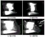
图1为本发明焊接偏差测定方法的典型的四种熔池图像的示意图;Fig. 1 is the schematic diagram of typical four kinds of molten pool images of the welding deviation measuring method of the present invention;
图2为本发明焊接偏差测定装置的一实施例的结构示意图;FIG. 2 is a schematic structural diagram of an embodiment of the welding deviation measuring device of the present invention;
图3为本发明自动焊接系统的一实施例的结构示意图;3 is a schematic structural diagram of an embodiment of the automatic welding system of the present invention;
图4为本发明焊接偏差测定方法的第一实施例的流程示意图;FIG. 4 is a schematic flowchart of the first embodiment of the welding deviation measuring method of the present invention;
图5为本发明焊接偏差测定方法的第二实施例的流程示意图;FIG. 5 is a schematic flowchart of the second embodiment of the welding deviation measuring method of the present invention;
图6为本发明焊接偏差测定方法的第三实施例的流程示意图;FIG. 6 is a schematic flowchart of a third embodiment of the welding deviation measuring method of the present invention;
图7为本发明焊接偏差测定方法的第四实施例的流程示意图;FIG. 7 is a schematic flowchart of a fourth embodiment of the welding deviation measuring method of the present invention;
图8为本发明焊接偏差测定方法的第一熔池图像的示意图;8 is a schematic diagram of a first molten pool image of the method for measuring welding deviation of the present invention;
图9为本发明焊接偏差测定方法的第二熔池图像的流程示意图;FIG. 9 is a schematic flowchart of the second molten pool image of the welding deviation measuring method of the present invention;
图10为本发明焊接偏差测定方法的第五实施例的流程示意图;FIG. 10 is a schematic flowchart of a fifth embodiment of the welding deviation measurement method of the present invention;
图11为本发明焊接偏差测定方法的第六实施例的流程示意图;FIG. 11 is a schematic flowchart of the sixth embodiment of the welding deviation measuring method of the present invention;
图12为本发明焊接偏差测定方法的焊接偏差值的数据分析示意图;12 is a schematic diagram of data analysis of welding deviation value of the welding deviation measuring method of the present invention;
图13为本发明焊接偏差测定方法的第七实施例的流程示意图;FIG. 13 is a schematic flowchart of the seventh embodiment of the welding deviation measuring method of the present invention;
图14为本发明焊接偏差测定方法的第八实施例的流程示意图;FIG. 14 is a schematic flowchart of the eighth embodiment of the welding deviation measuring method of the present invention;
图15为本发明焊接偏差测定验证方法的熔池图像中焊枪中心与焊丝之间的距离分布图。15 is a distribution diagram of the distance between the center of the welding torch and the welding wire in the molten pool image of the welding deviation measurement and verification method of the present invention.
附图标号说明:Description of reference numbers:
本发明目的的实现、功能特点及优点将结合实施例,参照附图做进一步说明。The realization, functional characteristics and advantages of the present invention will be further described with reference to the accompanying drawings in conjunction with the embodiments.
具体实施方式Detailed ways
下面将结合本发明实施例中的附图,对本发明实施例中的技术方案进行清楚、完整地描述,显然,所描述的实施例仅仅是本发明的一部分实施例,而不是全部的实施例。基于本发明中的实施例,本领域普通技术人员在没有作出创造性劳动前提下所获得的所有其他实施例,都属于本发明保护的范围。The technical solutions in the embodiments of the present invention will be clearly and completely described below with reference to the accompanying drawings in the embodiments of the present invention. Obviously, the described embodiments are only a part of the embodiments of the present invention, not all of the embodiments. Based on the embodiments of the present invention, all other embodiments obtained by those of ordinary skill in the art without creative efforts shall fall within the protection scope of the present invention.
需要说明,若本发明实施例中有涉及方向性指示(诸如上、下、左、右、前、后……),则该方向性指示仅用于解释在某一特定姿态(如附图所示) 下各部件之间的相对位置关系、运动情况等,如果该特定姿态发生改变时,则该方向性指示也相应地随之改变。It should be noted that if there are directional indications (such as up, down, left, right, front, back, etc.) involved in the embodiments of the present invention, the directional indications are only used to explain a certain posture (as shown in the accompanying drawings). If the specific posture changes, the directional indication also changes accordingly.
另外,若本发明实施例中有涉及“第一”、“第二”等的描述,则该“第一”、“第二”等的描述仅用于描述目的,而不能理解为指示或暗示其相对重要性或者隐含指明所指示的技术特征的数量。由此,限定有“第一”、“第二”的特征可以明示或者隐含地包括至少一个该特征。另外,全文中出现的“和/或”的含义,包括三个并列的方案,以“A和/或B”为例,包括A方案、或B方案、或A和B同时满足的方案。另外,各个实施例之间的技术方案可以相互结合,但是必须是以本领域普通技术人员能够实现为基础,当技术方案的结合出现相互矛盾或无法实现时应当认为这种技术方案的结合不存在,也不在本发明要求的保护范围之内。In addition, if there are descriptions involving "first", "second", etc. in the embodiments of the present invention, the descriptions of "first", "second", etc. are only used for the purpose of description, and should not be construed as indicating or implying Its relative importance or implicitly indicates the number of technical features indicated. Thus, a feature delimited with "first", "second" may expressly or implicitly include at least one of that feature. In addition, the meaning of "and/or" in the whole text includes three parallel schemes. Taking "A and/or B" as an example, it includes scheme A, scheme B, or scheme satisfying both of A and B. In addition, the technical solutions between the various embodiments can be combined with each other, but must be based on the realization by those of ordinary skill in the art. When the combination of technical solutions is contradictory or cannot be realized, it should be considered that the combination of such technical solutions does not exist. , is not within the scope of protection required by the present invention.
经研究分析大量的由普通CCD摄像机采集的熔池图像后发现,焊缝特征明显的同时焊枪轮廓也较为清晰,且焊缝的位置和运动轨迹与焊枪具有一致性,因此需要提出一种通过焊枪的轮廓和焊缝的相对位置来测定出偏差量的焊接偏差测定方法,并对该方法进行可行性分析。After research and analysis of a large number of molten pool images collected by ordinary CCD cameras, it is found that the welding seam features are obvious and the contour of the welding gun is relatively clear, and the position and movement trajectory of the welding seam are consistent with the welding gun. The welding deviation measurement method is used to determine the deviation of the contour and the relative position of the welding seam, and the feasibility of the method is analyzed.
本发明实施例的主要解决方案是提出一种焊接偏差测定方法,所述焊接偏差测定方法包括如下步骤:The main solution of the embodiment of the present invention is to propose a method for measuring welding deviation, and the method for measuring welding deviation includes the following steps:
获取第一熔池图像和第二熔池图像,其中,所述第一熔池图像为基准熔池图像;acquiring a first molten pool image and a second molten pool image, wherein the first molten pool image is a reference molten pool image;
分别提取所述第一熔池图像和所述第二熔池图像的焊枪位置信息和焊缝位置信息;respectively extracting the welding torch position information and the welding seam position information of the first molten pool image and the second molten pool image;
根据所述第一熔池图像和所述第二熔池图像的焊枪位置信息和焊缝位置信息,计算获得焊接偏差值。The welding deviation value is obtained by calculation according to the welding torch position information and the welding seam position information of the first molten pool image and the second molten pool image.
本发明提出的解决方案中,首先拍照获得包括第一熔池图像和第二熔池图像的至少两张熔池图像,然后提取上述熔池图像中的焊枪位置信息和焊缝位置信息,以第一张为基准熔池图像,将基准熔池图像中的焊枪位置信息和焊缝位置信息作为位置基准,计算第二张熔池图像中的焊枪位置信息和焊缝位置信息与位置基准之间的偏差,然后根据现有的焊缝跟踪技术的实际经验,判断该偏差是否能满足焊缝跟踪的偏差要求,如果满足,则表明可根据焊枪与焊缝之间的位置偏差进行基于焊缝跟踪的自动焊接。请参阅图1,为熔池图像中的正常图像、偏暗图像、偏亮图像和飞溅图像,是较为典型的四种熔池图像,根据对大量的熔池图像观察后发现,四种熔池图像中的焊枪轮廓均较为清晰,特征较为明显,相比在熔池图像中辨别提取焊丝尖端,焊枪轮廓更加不容易受到干扰,因此,可使用被动视觉传感方法获得熔池图像,被动视觉传感方法具有实时监测熔池和观测焊缝位置的优势,不存在超前监测误差,同时只需要普通CCD摄像机拍照即可,节省了自动焊接设备成本。In the solution proposed by the present invention, at least two molten pool images including the first molten pool image and the second molten pool image are obtained by taking pictures first, and then the welding torch position information and the welding seam position information in the above molten pool images are extracted to obtain the first molten pool image As the reference molten pool image, the welding torch position information and the welding seam position information in the reference molten pool image are used as the position reference, and the deviation between the welding gun position information and the welding seam position information in the second molten pool image and the position reference is calculated, and then according to Based on the actual experience of the existing welding seam tracking technology, it is judged whether the deviation can meet the deviation requirements of the welding seam tracking. Please refer to Figure 1, which is the normal image, dark image, bright image and splash image in the molten pool image, which are four typical molten pool images. The outline of the welding torch in the image is relatively clear and the features are more obvious. Compared with distinguishing and extracting the tip of the welding wire in the image of the molten pool, the outline of the welding torch is less likely to be disturbed. Therefore, the passive vision sensing method can be used to obtain the image of the molten pool. The sensing method has the advantages of real-time monitoring of the molten pool and the position of the welding seam, and there is no advance monitoring error. At the same time, only ordinary CCD cameras are required to take pictures, which saves the cost of automatic welding equipment.
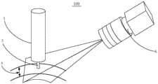
基于本发明提出的焊接偏差测定方法,本发明提出一种焊接偏差测定装置100,所述焊接偏差测定装置100包括视觉采集装置以及控制器(附图未示出),视觉采集装置包括用于朝向熔池的摄像头6,以拍摄得到第一熔池图像和第二熔池图像,控制器与视觉采集装置电性连接,控制器包括存储介质,存储介质存储有焊接偏差测定程序和焊接控制程序,其中,焊接偏差测定程序执行本发明实施例的焊接偏差测定方法的步骤,焊接控制程序执行步骤:根据焊接偏差值进行自动焊接的纠偏操作。Based on the welding deviation measuring method proposed by the present invention, the present invention provides a welding
具体地,如图2所示,所述焊接偏差测定装置100的本实施例中,焊枪1 对应采用截面为圆形的型式,使其在熔池图像中形状规则,焊丝3安装在焊枪1头部的正中间,摄像头6朝向焊枪1和焊缝4并进行多次拍照,其与竖直方向的夹角为60°,便于获得视角范围大、焊枪1与焊缝4干涉少的图像,视觉采集装置向控制器发送焊枪1的位置信息和焊缝4的位置信息,控制器根据上述位置信息计算焊接偏差,通过上述各装置,完成本发明实施例的焊接偏差测定方法的各个步骤,其中,焊接控制程序可执行自动焊接的纠偏操作。Specifically, as shown in FIG. 2 , in this embodiment of the welding
本领域技术人员可以理解,图2中示出的焊接偏差测定装置100可以安装在用于自动焊接的设备和系统上,以在进行实际自动焊接时进行偏差测定,也可以在实验室中为本发明实施例的焊接偏差测定方法所特定布置安装。Those skilled in the art can understand that the welding
本领域技术人员还可以理解,图2中示出的焊接偏差测定装置100的结构并不构成对焊接偏差测定装置100的限定,可以包括比图示更多或更少的部件,或者组合某些部件,或者不同的部件布置。Those skilled in the art can also understand that the structure of the welding
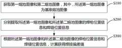
参照图4,为本发明的焊接偏差测定方法的第一实施例,包括:Referring to FIG. 4, it is the first embodiment of the welding deviation measuring method of the present invention, including:
S100:获取第一熔池图像和第二熔池图像,其中,所述第一熔池图像为基准熔池图像;S100: Obtain a first molten pool image and a second molten pool image, wherein the first molten pool image is a reference molten pool image;
本步骤中,摄像头对朝向焊枪和熔池的拍照,焊接偏差需要通过比较得出,因此需要得到包括第一熔池图像和第二熔池图像的至少两张图像,其中,第一熔池图像为基准熔池图像,在该图像中提出得到的信息均为基准信息,第一熔池图像的拍摄时间在前,第二熔池图像的拍摄时间在后,为了方便进行观察比较,各熔池图像可选取特征明显、清晰的图像,为了增强偏差测定的准确度,在获取第一熔池图像和第二熔池图像后,可另外拍摄获取多张熔池图像,提高试验样本的数量。In this step, the camera takes pictures of the welding torch and the molten pool, and the welding deviation needs to be obtained by comparison, so at least two images including the first molten pool image and the second molten pool image need to be obtained, wherein the first molten pool image For the reference molten pool image, the information proposed in this image is the reference information. The shooting time of the first molten pool image is earlier, and the shooting time of the second molten pool image is later. For the convenience of observation and comparison, the The images can be selected with obvious and clear features. In order to enhance the accuracy of the deviation determination, after the first and second molten pool images are obtained, additional images of the molten pool can be taken to increase the number of test samples.
S200:分别提取所述第一熔池图像和所述第二熔池图像的焊枪位置信息和焊缝位置信息;S200: Extract the welding torch position information and the welding seam position information of the first molten pool image and the second molten pool image respectively;
本步骤中,可以在熔池图像中建立坐标系,进而通过曲线方程或直线方程来表示焊枪位置信息和焊缝位置信息,根据对大量的熔池图像观察后发现,熔池图像中焊枪和焊缝的轮廓均较为清晰,特征明显,该步骤使得普通CCD 摄像机可应用于本发明的焊接偏差测定方法,进而节省了设备成本。In this step, a coordinate system can be established in the molten pool image, and then the welding torch position information and the welding seam position information can be represented by a curve equation or a straight line equation. The outline of the seam is relatively clear and the features are obvious. This step enables the ordinary CCD camera to be applied to the welding deviation measuring method of the present invention, thereby saving the equipment cost.
需要说明的是,在自动焊接的过程中,焊枪不断地摆动,使头部的焊丝在焊缝两边缘不断地摆动,进而完成焊接,而根据焊接工艺要求,焊枪在摆动到极限位置时,需停顿以充分熔透被焊接设备,具体地,本实施例中,设置了一条环形机加工焊缝,该焊缝宽度均匀,有利于焊接偏差值的数据分析,焊枪在焊缝两边缘来回摆动,并且在两边缘处停顿300ms-350ms以充分熔透焊缝两边缘,为了避免在运动状态下拍摄焊枪导致熔池图像中存在拖影的现象,可在焊腔在焊缝两边缘停顿时进行拍照。It should be noted that in the process of automatic welding, the welding torch continuously swings, so that the welding wire of the head swings continuously on both edges of the welding seam to complete the welding. According to the welding process requirements, when the welding torch swings to the limit position, it needs Pause to fully penetrate the equipment to be welded. Specifically, in this embodiment, a ring-shaped machined welding seam is set. The width of the welding seam is uniform, which is conducive to the data analysis of the welding deviation value. The welding torch swings back and forth on both edges of the welding seam. And pause at the two edges for 300ms-350ms to fully penetrate the two edges of the weld. In order to avoid the phenomenon of smear in the molten pool image caused by shooting the welding torch in a moving state, you can take pictures when the welding cavity stops at both edges of the weld. .
S300:根据所述第一熔池图像和所述第二熔池图像的焊枪位置信息和焊缝位置信息,计算获得焊接偏差值;S300: Calculate and obtain a welding deviation value according to the welding torch position information and the welding seam position information of the first molten pool image and the second molten pool image;
本步骤中,可以通过S200步骤中的曲线方程或直线方程来进行计算,使结果更准确,较为优选的方式是以像素值为单位进行计算,进一步提高结果的精准度。焊接偏差值的计算结果与现有的基于焊缝跟踪的自动焊接方法中的偏差范围进行比较,进而可判断出根据焊枪位置信息和焊缝位置信息计算获得的焊接偏差值是否满足焊缝跟踪的要求。In this step, the curve equation or the straight line equation in step S200 can be used for calculation to make the result more accurate, and a more preferable way is to perform the calculation in units of pixel values to further improve the accuracy of the result. The calculation result of the welding deviation value is compared with the deviation range of the existing automatic welding method based on welding seam tracking, and then it can be judged whether the welding deviation value calculated according to the position information of the welding torch and the position information of the welding seam meets the requirements of the welding seam tracking. Require.
需要说明的是,如果根据焊枪位置信息和焊缝位置信息计算获得的焊接偏差值满足要求,则表明在熔池图像中提取焊枪位置信息进而最终实现实时基于焊缝跟踪的自动焊接方法是可行的。该自动焊接方法可实时监测熔池,观测熔池中焊枪的位置,不存在超前监测误差,进而实时快速地进行焊缝跟踪和焊枪纠偏,该自动焊接方法可使用普通CCD摄像机,进而降低自动焊接设备成本。It should be noted that if the welding deviation value calculated according to the welding gun position information and the welding seam position information meets the requirements, it indicates that it is feasible to extract the welding gun position information from the molten pool image and finally realize the real-time automatic welding method based on welding seam tracking. . The automatic welding method can monitor the molten pool in real time, observe the position of the welding torch in the molten pool, and there is no advance monitoring error, so as to quickly perform welding seam tracking and welding torch deviation correction in real time. The automatic welding method can use ordinary CCD cameras, thereby reducing automatic welding. equipment cost.
本实施例中,首先拍照获得包括第一熔池图像和第二熔池图像的至少两张熔池图像,然后提取上述熔池图像中的焊枪位置信息和焊缝位置信息,以第一张为基准熔池图像,将基准熔池图像中的焊枪位置信息和焊缝位置信息作为位置基准,计算第二张熔池图像中的焊枪位置信息和焊缝位置信息与位置基准之间的偏差,然后根据现有的焊缝跟踪技术的实际经验,判断该偏差是否能满足焊缝跟踪的偏差要求,如果满足,则可根据焊枪与焊缝之间的位置偏差进行基于焊缝跟踪的自动焊接。In this embodiment, at least two molten pool images including the first molten pool image and the second molten pool image are obtained by taking pictures first, and then the welding torch position information and the welding seam position information in the above molten pool images are extracted, and the first molten pool image is used as the reference for melting Pool image, using the welding gun position information and the welding seam position information in the reference molten pool image as the position reference, calculate the deviation between the welding gun position information and the welding seam position information in the second molten pool image and the position reference, and then according to the existing Based on the actual experience of the welding seam tracking technology, it is judged whether the deviation can meet the deviation requirements of the welding seam tracking.
进一步地,参照图5,基于前述第一实施例提出本发明焊接偏差测定方法的第二实施例,本实施例中,所述焊枪位置信息为焊枪轮廓信息,所述焊缝位置信息为焊缝轮廓信息,步骤S200包括:Further, referring to FIG. 5 , a second embodiment of the welding deviation measurement method of the present invention is proposed based on the aforementioned first embodiment. In this embodiment, the welding torch position information is welding torch profile information, and the welding seam position information is welding seam Outline information, step S200 includes:
S201:分别提取所述第一熔池图像和所述第二熔池图像的焊枪轮廓信息和焊缝轮廓信息。S201: Extract the welding torch contour information and the welding seam contour information of the first molten pool image and the second molten pool image, respectively.
本步骤中,请参阅图1,经过大量观察发现,各熔池图像中的焊枪轮廓和焊缝轮廓特征较为明显、易于辨别,不易受到干扰,作为试验样本十分稳定,而且两者均为规则图像,有利于后续进行计算处理。本实施例中,可对各熔池图像中的焊枪轮廓和焊缝轮廓进行局部增强和图像闭运算,使其轮廓更加清晰、边界更加平滑。在本实施例中,根据第一熔池图像和所述第二熔池图像的焊枪轮廓信息和焊缝轮廓信息,计算获得焊接偏差值。In this step, please refer to Figure 1. After a lot of observation, it is found that the characteristics of the welding torch contour and the welding seam contour in each molten pool image are relatively obvious, easy to identify, and not easily disturbed. They are very stable as test samples, and both are regular images. , which is conducive to subsequent calculation processing. In this embodiment, local enhancement and image closing operations can be performed on the contour of the welding torch and the contour of the welding seam in each molten pool image to make the contour clearer and the boundary smoother. In this embodiment, the welding deviation value is obtained by calculation according to the welding torch contour information and the welding seam contour information of the first molten pool image and the second molten pool image.
进一步地,参照图6,基于前述第二实施例提出本发明焊接偏差测定方法的第三实施例,本实施例中,步骤S300包括:Further, referring to FIG. 6 , a third embodiment of the method for determining the welding deviation of the present invention is proposed based on the aforementioned second embodiment. In this embodiment, step S300 includes:
S310:根据所述第一熔池图像和所述第二熔池图像的焊枪轮廓信息和焊缝轮廓信息,获取所述第一熔池图像和所述第二熔池图像中的焊枪中心位置信息和焊缝边缘位置信息。S310: According to the welding torch profile information and the welding seam profile information of the first molten pool image and the second molten pool image, obtain the welding torch center position information in the first molten pool image and the second molten pool image and weld edge position information.
本步骤中,通过对各熔池图像的大量观察后发现,焊枪轮廓十分规则且稳定,其特征明显,本实施例中,找到其轮廓的中心点位置,作为焊枪位置信息,可通过对熔池图像进行采样和曲线拟合的现有技术手段实现。In this step, after a large number of observations of each molten pool image, it is found that the contour of the welding torch is very regular and stable, and its characteristics are obvious. In this embodiment, the center point position of the contour is found as the welding torch position information. Image sampling and curve fitting are implemented by prior art means.
S320:根据所述第一熔池图像和所述第二熔池图像中的焊枪中心位置信息和焊缝边缘位置信息,计算获得第一熔池图像中焊枪中心与焊缝两边缘之间的距离d0和di,作为基准位置参数,计算获得第二熔池图像中焊枪中心与焊缝两边缘之间的距离w0和wi,作为测定位置参数;S320: Calculate the distance between the center of the welding torch and the two edges of the welding seam in the first molten pool image according to the position information of the welding torch center and the welding seam edge position information in the first molten pool image and the second molten pool image d0 and di , as reference position parameters, calculate and obtain the distances w0 andwi between the center of the welding torch and the two edges of the weld in the second molten pool image, as the measured position parameters;
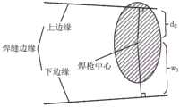
本步骤中,以焊枪中心与焊缝两边缘之间的距离作为位置参数进行计算,焊枪中心与焊缝两边缘之间的距离之和即为焊枪的摆幅。参阅图8和图9,其中图7为第一熔池图像的示意图,图8为第二熔池图像的示意图,焊缝两边缘分别为上边缘和下边缘,由于摄像头视角的原因,圆柱形焊枪在熔池图像中呈一段椭圆形弧线,焊缝在图像上近似于梯形,因此短距离内可视为梯形,在第一熔池图像和第二熔池图像中,焊枪中心与上边缘的距离分别为d0和di,焊枪中心与下边缘的距离分别为w0和wi,以d0和di作为计算所需参数,d0和di的差值即为焊枪在焊接过程中的偏差值(当然也可以以w0和wi作为计算所需参数)。在自动焊接过程中,焊枪发生偏差时,将导致其活动路径与焊缝发生偏移,此时可根据焊枪位置的偏差值控制焊枪使其回到正确位置,或者控制其摆幅以抵消位置偏差,或者上述两种方式同时实施,最终提高自动焊接的精度。In this step, the distance between the center of the welding torch and the two edges of the welding seam is used as a position parameter for calculation, and the sum of the distances between the center of the welding torch and the two edges of the welding seam is the swing of the welding torch. Referring to Figures 8 and 9, Figure 7 is a schematic diagram of the first molten pool image, Figure 8 is a schematic diagram of the second molten pool image, the two edges of the weld are the upper edge and the lower edge, respectively, due to the camera angle of view, the cylindrical shape. The welding torch shows an elliptical arc in the molten pool image, and the welding seam is similar to a trapezoid in the image, so it can be regarded as a trapezoid in a short distance. In the first molten pool image and the second molten pool image, the center of the welding torch and the upper edge The distances between
需要说明的是,本实施例中以像素数为单位进行计算,使计算更快更准确。It should be noted that, in this embodiment, the calculation is performed in units of the number of pixels, so that the calculation is faster and more accurate.
S330:根据所述基准位置参数和所述测定位置参数计算获得所述焊接偏差值。S330: Calculate and obtain the welding deviation value according to the reference position parameter and the measured position parameter.
本实施例中,在各熔池图像中可清楚、简单地得到焊枪中心与焊缝两边缘之间的距离,进而得到焊枪的摆幅和焊枪的位置偏差,在自动焊接过程中,焊枪位置发生偏差时,可根据焊枪位置的偏差值控制焊枪使其回到正确位置,或者控制其摆幅以抵消位置偏差,或者上述两种方式同时实施,最终提高自动焊接的精度。In this embodiment, the distance between the center of the welding torch and the two edges of the welding seam can be clearly and simply obtained in each molten pool image, and then the swing of the welding torch and the positional deviation of the welding torch can be obtained. During the automatic welding process, the position of the welding torch occurs When there is a deviation, the welding torch can be controlled to return to the correct position according to the deviation value of the welding torch position, or its swing can be controlled to offset the position deviation, or the above two methods can be implemented at the same time, which ultimately improves the accuracy of automatic welding.
进一步地,参照图7,基于前述第三实施例提出本发明焊接偏差测定方法的第四实施例,本实施例中,步骤S330包括:Further, referring to FIG. 7 , a fourth embodiment of the method for determining welding deviation of the present invention is proposed based on the aforementioned third embodiment. In this embodiment, step S330 includes:
S331:计算获得所述焊枪位置偏差值D=di-d0。S331: Calculate and obtain the welding torch position deviation value D=di -d0 .
本步骤中,得到第二熔池图像中焊枪位置相对于基准图像中焊枪位置的偏差,在自动焊接过程中,焊枪位置发生偏差时,可根据焊枪位置的偏差值控制焊枪使其回到正确位置,进而完成自动焊接。In this step, the deviation of the welding torch position in the second molten pool image relative to the welding torch position in the reference image is obtained. During the automatic welding process, when the welding torch position deviates, the welding torch can be controlled to return to the correct position according to the deviation value of the welding torch position , and then complete the automatic welding.
进一步地,本实施例中,除第一熔池图像和第二熔池图像外,还获得了多张满足试验要求的熔池图像,在每张熔池图像中均计算得到焊接偏差值,并将得到的多个焊接偏差值进行数据分析,横坐标表示不同的熔池图像,纵坐标表示对应的焊接偏差值,参照图12中上方两张数据分析图,为焊枪位置偏差数据分析结果,在完成本焊接偏差测定方法实施例的焊接偏差测定装置 100中,焊枪处于自由运动的状态,焊缝宽度均匀,焊接车的活动路径与焊缝不平行,且逐渐发生偏移,从图中可以看出,焊枪在同一方向上跟随焊接车逐渐偏移,验证了本发明的焊接偏差测定方法对焊枪位置偏差测定的可靠性。Further, in this embodiment, in addition to the first molten pool image and the second molten pool image, a plurality of molten pool images that meet the test requirements are also obtained, and the welding deviation value is calculated in each molten pool image, and will be obtained. Perform data analysis on multiple welding deviation values, the abscissa represents different molten pool images, and the ordinate represents the corresponding welding deviation value. Referring to the upper two data analysis graphs in Figure 12, it is the analysis result of the welding torch position deviation data. In the welding
或者,参照图10,基于前述第三实施例提出本发明焊接偏差测定方法的第五实施例,本实施例中,步骤S330包括:Alternatively, referring to FIG. 10 , a fifth embodiment of the welding deviation determination method of the present invention is proposed based on the aforementioned third embodiment. In this embodiment, step S330 includes:
S332:计算获得所述基准图像中焊枪中心与焊缝两边缘之间的距离之和 W0=d0+w0,作为焊枪的基准摆幅值,计算获得第二熔池图像中焊枪中心与焊缝两边缘之间的距离之和Wi=di+wi,作为焊枪的测定摆幅值,计算获得所述焊枪摆幅偏差值W=Wi-W0。S332: Calculate and obtain the sum of the distances between the center of the welding torch and the two edges of the welding seam in the reference image, W0 =d0 +w0 , as the reference swing value of the welding torch, calculate and obtain the center of the welding torch in the second molten pool image and The sum of the distances between the two edges of the welding seam, Wi =di +wi , is used as the measured swing value of the welding gun, and the swing deviation value of the welding gun is calculated to obtain W=Wi -W0 .
本步骤中,得到第二熔池图像中焊枪摆幅对于基准图像中焊枪摆幅的偏差,在自动焊接过程中,焊枪位置发生偏差时,可控制焊枪的摆幅,使其极限位置正确地停留在焊缝两边缘,进而完成自动焊接。In this step, the deviation of the welding torch swing in the second molten pool image from the welding torch swing in the reference image is obtained. During the automatic welding process, when the welding torch position deviates, the welding torch swing can be controlled to make it stay at the limit position correctly. Automatic welding is then completed on both edges of the weld.
进一步地,参照图12中最下方的数据分析图,为焊枪摆幅偏差数据分析结果,在完成本焊接偏差测定方法实施例的焊接偏差测定装置100中,焊枪处于自由运动的状态,焊缝宽度均匀,焊接车的活动路径与焊缝不平行,且逐渐发生偏移,本实施例中获得了多张熔池图像,从图中可以计算得到焊枪摆幅偏差值的范围Wr为(Wmin-W0)≤Wr≤(Wmax-W0),将各熔池图像中的焊枪摆幅偏差值带入计算得到其范围为-0.207mm≤Wr≤0.205mm,其数值较小且稳定,验证了本焊接偏差测定方法对焊枪摆幅偏差值测定的可靠性。Further, referring to the data analysis diagram at the bottom in FIG. 12 , which is the data analysis result of the swing deviation of the welding torch, in the welding
进一步地,参照图11,基于前述第三实施例提出本发明焊接偏差测定方法的第六实施例,本实施例中,测定焊枪位置偏差值和焊枪摆幅偏差值同时实施,步骤S330包括:Further, referring to FIG. 11 , a sixth embodiment of the welding deviation measuring method of the present invention is proposed based on the aforementioned third embodiment. In this embodiment, the measurement of the welding torch position deviation value and the welding torch swing deviation value is performed simultaneously, and step S330 includes:
S331:计算获得所述焊枪位置偏差值D=di-d0;S331: Calculate and obtain the position deviation value of the welding torch D=di -d0 ;
S332:计算获得所述基准图像中焊枪中心与焊缝两边缘之间的距离之和 W0=d0+w0,作为焊枪的基准摆幅值,计算获得第二熔池图像中焊枪中心与焊缝两边缘之间的距离之和Wi=di+wi,作为焊枪的测定摆幅值,计算获得所述焊枪摆幅偏差值W=Wi-W0。S332: Calculate and obtain the sum of the distances between the center of the welding torch and the two edges of the welding seam in the reference image, W0 =d0 +w0 , as the reference swing value of the welding torch, calculate and obtain the center of the welding torch in the second molten pool image and The sum of the distances between the two edges of the welding seam, Wi =di +wi , is used as the measured swing value of the welding gun, and the swing deviation value of the welding gun is calculated to obtain W=Wi -W0 .
本实施例中,可根据焊枪位置的偏差值控制焊枪使其回到正确位置,同时控制其摆幅以抵消位置偏差,使其极限位置正确地停留在焊缝两边缘,最终提高自动焊接的精度。In this embodiment, the welding torch can be controlled to return to the correct position according to the deviation value of the welding torch position, and the swing of the welding torch can be controlled to offset the position deviation, so that the limit position can stay at the two edges of the welding seam correctly, and finally the accuracy of automatic welding can be improved. .
进一步地,参照图13,基于前述第三实施例提出本发明焊接偏差测定方法的第七实施例,本实施例中,步骤S310包括:Further, referring to FIG. 13 , a seventh embodiment of the method for determining welding deviation of the present invention is proposed based on the aforementioned third embodiment. In this embodiment, step S310 includes:
S311:对所述第一熔池图像和所述第二熔池图像中的焊枪轮廓和焊缝轮廓进行边缘点采样,得到焊枪轮廓采样点和焊缝轮廓采样点;S311: Perform edge point sampling on the welding gun contour and the welding seam contour in the first molten pool image and the second molten pool image, to obtain the welding gun contour sampling point and the welding seam contour sampling point;
S312:对所述焊枪轮廓采样点使用曲线拟合算法得到所述焊枪轮廓的曲线方程,所述焊枪中心位置信息包括所述曲线方程的中心点位置;S312: Use a curve fitting algorithm for the welding torch contour sampling points to obtain a curve equation of the welding torch contour, and the welding torch center position information includes the center point position of the curve equation;
S313:对所述焊缝轮廓采样点使用线性拟合,得到所述焊缝轮廓的直线方程,所述焊缝边缘位置信息包括所述直线方程。S313: Use linear fitting on the welding seam contour sampling points to obtain a straight line equation of the welding seam contour, and the welding seam edge position information includes the straight line equation.
本实施例中,由于电弧光明暗度的变化和焊渣飞溅的影响,焊缝和焊枪的位置信息在熔池图像中受到干扰,为了消除干扰,本实施例中,对焊缝和焊枪的轮廓进行边缘点采样,提升各熔池图像用于提取焊缝和焊枪的轮廓特征时的稳定性。In this embodiment, the position information of the welding seam and the welding torch is disturbed in the molten pool image due to the change of the arc brightness and the influence of the welding slag splash. Perform edge point sampling to improve the stability of each weld pool image when it is used to extract contour features of welds and welding guns.
进一步地,基于本发明实施例的焊接偏差测定装置100,焊枪采用截面为圆形的型式,摄像头与竖直方向的夹角为60°,因此焊枪在熔池图像中呈现出椭圆形的圆弧段,对所述焊枪轮廓采样点使用曲线拟合算法得到所述焊枪轮廓的曲线方程为椭圆方程,该椭圆方程的中心点即为焊枪的中心点,在其他实施例中,如果摄像头的位置发生变化,所述焊枪轮廓的曲线方程可以为圆形等。Further, based on the welding
进一步地,参照图14,基于前述第七实施例提出本发明焊接偏差测定方法的第八实施例,本实施例中,步骤S311包括:Further, referring to FIG. 14 , an eighth embodiment of the welding deviation measuring method of the present invention is proposed based on the aforementioned seventh embodiment. In this embodiment, step S311 includes:
S311a:在每一熔池图像中选定目标区域,所述目标区域中包括焊枪轮廓,在目标区域内画出多个剖面线,计算目标区域内垂直于剖面线方向上的以单位像素为间隔的灰度平均值,并作为该剖面线上的采样点的灰度值;S311a: Select a target area in each molten pool image, the target area includes the outline of the welding torch, draw a plurality of section lines in the target area, and calculate the unit pixel interval in the direction perpendicular to the section line in the target area The grayscale average value of , and use it as the grayscale value of the sampling point on the section line;
S311b:使用高斯滤波对多个剖面线进行光滑处理;S311b: Use Gaussian filtering to smooth multiple section lines;
S311c:对目标区域中光滑处理后的多个剖面线求导并获得导数极值,选取导数极值大于零的剖面线对应的采样点作为焊枪轮廓采样点。S311c: Deriving the smoothed multiple section lines in the target area and obtaining the extreme value of the derivative, and selecting the sampling point corresponding to the section line with the extreme value of the derivative greater than zero as the welding gun contour sampling point.
本实施例中,以焊枪轮廓采样点为例,显然焊缝轮廓采样点也可以通过上述步骤实施,其目标区域选定为包括焊缝轮廓的部分即可,本实施例中增强了采样点的精准性和稳定性。In this embodiment, taking the welding torch contour sampling point as an example, it is obvious that the welding seam contour sampling point can also be implemented through the above steps, and the target area can be selected as the part including the welding seam contour. In this embodiment, the sampling point is enhanced. Accuracy and stability.
进一步地,本发明的焊接偏差测定方法中,通过聚类算法对焊枪轮廓采样点和焊缝轮廓采样点进行筛选,以进一步消除采样点受到的干扰,提升焊枪轮廓和焊缝轮廓的拟合精度。聚类算法的核心步骤为同类型对象的判别,判别条件设计的优劣决定了分组的精度,在该聚类算法中使用欧式几何中的距离和方向两个特征,再结合各边缘采样点的分布规律设置阈值,判别出两个对象是否为同一子集。Further, in the welding deviation determination method of the present invention, the sampling points of the welding torch contour and the welding seam contour sampling points are screened by a clustering algorithm, so as to further eliminate the interference of the sampling points and improve the fitting accuracy of the welding torch contour and the welding seam contour. . The core step of the clustering algorithm is the discrimination of objects of the same type. The quality of the discriminant condition design determines the accuracy of the grouping. In this clustering algorithm, two features of distance and direction in Euclidean geometry are used, and then combined with the characteristics of each edge sampling point. The distribution law sets a threshold to determine whether two objects are the same subset.
以焊枪轮廓采样点为例,设两个焊枪边缘采样点A(x1,y1),B(x2,y2),当A、 B满足条件:Taking the welding torch contour sampling point as an example, set two welding torch edge sampling points A(x1 , y1 ) and B(x2 , y2 ), when A and B meet the conditions:

时,即A、B为同一子集。其中DT为A、B两点间的距离阈值,θT为A、B 两点间角度阈值。该聚类算法的实现步骤为:, that is, A and B are the same subset. DT is the distance threshold between points A and B, and θT is the angle threshold between points A and B. The implementation steps of this clustering algorithm are:
1、算法开始,逐行读取焊枪轮廓采样点;1. The algorithm starts, and the sampling points of the welding torch contour are read line by line;
2、第一行采样点的个数为n,则创建C1,C2,…,Cn个子集,记为Ci;2. The number of sampling points in the first row is n, then create C1 , C2 , ..., Cn subsets, denoted as Ci ;
3、读取第二行采样点,逐个采样点均使用公式(6)计算与Ci的归属关系,满足条件则为Ci子集的成员,与Ci都不满足条件则重新创建子集C(n+1),以此类推,新子集为C(n+2),C(n+3),…,同样记为Ci;3. Read the sampling points in the second row, and use formula (6) to calculate the attribution relationship with Ci for each sampling point. If the condition is met, it is a member of the subset of Ci , and if it does not meet the condition with Ci , the subset is re-created C(n+1) , and so on, the new subsets are C(n+2) , C(n+3) , ..., also denoted as Ci ;
4、读取第i行采样点,执行步骤2操作;4. Read the sampling point of the i-th row and perform the operation of
5、采样点读取并计算完毕,算法结束。5. After the sampling point is read and calculated, the algorithm ends.
进一步地,本发明实施例的焊接偏差测定方法中,对焊接偏差测定值提出了如下验证方法:Further, in the welding deviation measurement method of the embodiment of the present invention, the following verification method is proposed for the welding deviation measurement value:
根据所述第一熔池图像和所述第二熔池图像的焊枪轮廓信息和焊缝轮廓信息,获取所述第一熔池图像和所述第二熔池图像中的焊枪中心位置信息和焊缝边缘位置信息;根据所述第一熔池图像和所述第二熔池图像中的焊枪中心位置信息和焊丝位置信息;根据所述焊枪中心位置信息和所述焊丝位置信息计算获得焊枪中心与焊丝之间的距离dp。According to the welding torch profile information and the welding seam profile information of the first molten pool image and the second molten pool image, obtain the welding torch center position information and welding seam profile information in the first molten pool image and the second molten pool image Seam edge position information; according to the welding torch center position information and welding wire position information in the first molten pool image and the second molten pool image; according to the welding torch center position information and the welding wire position information, calculate and obtain the welding torch center and the welding wire position information. The distance dp between the wires.
为了进一步提高验证的可信度,在该验证方法中,选取了50张能同时提取到焊枪和焊丝位置信息的熔池图像,然后计算每一张熔池图像中焊枪中心与焊丝之间的距离dp(p=1,2,,,50),参照图14,为距离dp的分布图,经计算得到,在选取的50张熔池图像中,dp的范围为0≤dp≤0.2mm,根据自动焊接领域的经验,该范围满足自动焊接的偏差范围,表明本发明的焊接偏差测定方法具有较高的可靠性。In order to further improve the credibility of the verification, in this verification method, 50 molten pool images that can simultaneously extract the position information of the welding gun and the welding wire are selected, and then the distance dp ( p=1, 2, , 50), referring to Figure 14, it is the distribution map of the distance dp, after calculation, in the selected 50 molten pool images, the range of dp is 0≤dp≤0.2mm, according to the automatic welding field Experience shows that this range satisfies the deviation range of automatic welding, indicating that the welding deviation measuring method of the present invention has high reliability.
基于本发明实施例的焊接偏差测定方法的试验结果,本发明还提出一种自动焊接系统200,所述自动焊接系统200包括焊枪1、驱动装置5、视觉采集装置以及控制装置,焊枪1可摆动地安装于焊接车2,驱动装置5安装于焊接车2,用以驱动焊枪1摆动,视觉采集装置安装于焊接车2,视觉采集装置包括用于朝向熔池的摄像头6,以拍摄得到第一熔池图像和第二熔池图像,控制装置与驱动装置5和视觉采集装置电性连接,控制装置包括处理器和存储介质,存储器存储有焊接偏差测定程序和焊接控制程序,其中,焊接偏差测定程序执行如上所述的焊接偏差测定方法的步骤,焊接控制程序执行步骤:根据焊接偏差值进行自动焊接的纠偏操作。Based on the test results of the welding deviation determination method according to the embodiment of the present invention, the present invention further proposes an
如图3所示,本发明实施例的自动焊接系统200以焊接偏差测定装置100 为基础进行布置安装,本领域技术人员可以理解,图3中示出的自动焊接系统200的结构并不构成对自动焊接系统200的限定,在其他实施例中,自动焊接系统200可以包括比图示更多或更少的部件,或者组合某些部件,或者不同的部件布置。As shown in FIG. 3 , the
本发明实施例的自动焊接系统200具有实时监测熔池和观测焊缝位置的优势,不存在超前监测误差,同时只需要普通CCD摄像机拍照即可,节省了自动焊接设备成本。The
以上所述仅为本发明的优选实施例,并非因此限制本发明的专利范围,凡是在本发明的发明构思下,利用本发明说明书及附图内容所作的等效结构变换,或直接/间接运用在其他相关的技术领域均包括在本发明的专利保护范围内。The above descriptions are only the preferred embodiments of the present invention, and are not intended to limit the scope of the present invention. Under the inventive concept of the present invention, the equivalent structural transformations made by the contents of the description and drawings of the present invention, or the direct/indirect application Other related technical fields are included in the scope of patent protection of the present invention.
Claims (10)
Translated fromChinesePriority Applications (1)
| Application Number | Priority Date | Filing Date | Title |
|---|---|---|---|
| CN201911103567.0ACN110773840B (en) | 2019-11-12 | 2019-11-12 | Welding deviation determination method, device and automatic welding system |
Applications Claiming Priority (1)
| Application Number | Priority Date | Filing Date | Title |
|---|---|---|---|
| CN201911103567.0ACN110773840B (en) | 2019-11-12 | 2019-11-12 | Welding deviation determination method, device and automatic welding system |
Publications (2)
| Publication Number | Publication Date |
|---|---|
| CN110773840Atrue CN110773840A (en) | 2020-02-11 |
| CN110773840B CN110773840B (en) | 2021-09-24 |
Family
ID=69390696
Family Applications (1)
| Application Number | Title | Priority Date | Filing Date |
|---|---|---|---|
| CN201911103567.0AActiveCN110773840B (en) | 2019-11-12 | 2019-11-12 | Welding deviation determination method, device and automatic welding system |
Country Status (1)
| Country | Link |
|---|---|
| CN (1) | CN110773840B (en) |
Cited By (7)
| Publication number | Priority date | Publication date | Assignee | Title |
|---|---|---|---|---|
| CN111570974A (en)* | 2020-05-12 | 2020-08-25 | 湖北文理学院 | Welding deviation measuring method and device based on synchronous drawing and automatic welding system |
| CN111570975A (en)* | 2020-05-12 | 2020-08-25 | 湖北文理学院 | Welding deviation measurement method, device and automatic welding system based on synchronous mapping |
| CN113210805A (en)* | 2021-05-11 | 2021-08-06 | 浙江清华长三角研究院 | MIG welding deviation rectifying method based on industrial thermal imager and visible light camera double vision |
| CN114160921A (en)* | 2021-11-22 | 2022-03-11 | 湖北文理学院 | Welding control method and control device for welding robot and welding robot |
| CN114669932A (en)* | 2021-12-16 | 2022-06-28 | 浙江大华技术股份有限公司 | Intelligent welding method and related device |
| CN114714355A (en)* | 2022-04-14 | 2022-07-08 | 广州东焊智能装备有限公司 | Embedded vision tracking control system of autonomous mobile welding robot |
| CN114841959A (en)* | 2022-05-05 | 2022-08-02 | 广州东焊智能装备有限公司 | Automatic welding method and system based on computer vision |
Citations (6)
| Publication number | Priority date | Publication date | Assignee | Title |
|---|---|---|---|---|
| US5275327A (en)* | 1992-10-13 | 1994-01-04 | Eg&G Idaho, Inc. | Integrated optical sensor |
| CN102814574A (en)* | 2012-09-06 | 2012-12-12 | 江苏科技大学 | Narrow gap welding monitoring and welding line deviation detecting method based on infrared vision sensing |
| CN105689859A (en)* | 2014-11-25 | 2016-06-22 | 佛山市高明区生产力促进中心 | Connecting method and device for various metals |
| CN108247179A (en)* | 2017-12-15 | 2018-07-06 | 太原科技大学 | I shape grooves CO based on crater image2Weld deviation detecting method and device |
| CN108620714A (en)* | 2018-07-06 | 2018-10-09 | 太原科技大学 | Welding deviation detecting system based on the molten baths GMAW contour feature and its detection method |
| CN108637435A (en)* | 2018-05-16 | 2018-10-12 | 华南理工大学 | A kind of three-dimensional seam tracking system and method for view-based access control model and arc voltage sensing |
- 2019
- 2019-11-12CNCN201911103567.0Apatent/CN110773840B/enactiveActive
Patent Citations (6)
| Publication number | Priority date | Publication date | Assignee | Title |
|---|---|---|---|---|
| US5275327A (en)* | 1992-10-13 | 1994-01-04 | Eg&G Idaho, Inc. | Integrated optical sensor |
| CN102814574A (en)* | 2012-09-06 | 2012-12-12 | 江苏科技大学 | Narrow gap welding monitoring and welding line deviation detecting method based on infrared vision sensing |
| CN105689859A (en)* | 2014-11-25 | 2016-06-22 | 佛山市高明区生产力促进中心 | Connecting method and device for various metals |
| CN108247179A (en)* | 2017-12-15 | 2018-07-06 | 太原科技大学 | I shape grooves CO based on crater image2Weld deviation detecting method and device |
| CN108637435A (en)* | 2018-05-16 | 2018-10-12 | 华南理工大学 | A kind of three-dimensional seam tracking system and method for view-based access control model and arc voltage sensing |
| CN108620714A (en)* | 2018-07-06 | 2018-10-09 | 太原科技大学 | Welding deviation detecting system based on the molten baths GMAW contour feature and its detection method |
Non-Patent Citations (1)
| Title |
|---|
| 郭波等: "基于视觉传感的CO2焊焊接偏差识别", 《华南理工大学学报》* |
Cited By (10)
| Publication number | Priority date | Publication date | Assignee | Title |
|---|---|---|---|---|
| CN111570974A (en)* | 2020-05-12 | 2020-08-25 | 湖北文理学院 | Welding deviation measuring method and device based on synchronous drawing and automatic welding system |
| CN111570975A (en)* | 2020-05-12 | 2020-08-25 | 湖北文理学院 | Welding deviation measurement method, device and automatic welding system based on synchronous mapping |
| CN111570975B (en)* | 2020-05-12 | 2022-04-05 | 湖北文理学院 | Welding deviation measurement method, device and automatic welding system based on synchronous mapping |
| CN113210805A (en)* | 2021-05-11 | 2021-08-06 | 浙江清华长三角研究院 | MIG welding deviation rectifying method based on industrial thermal imager and visible light camera double vision |
| CN114160921A (en)* | 2021-11-22 | 2022-03-11 | 湖北文理学院 | Welding control method and control device for welding robot and welding robot |
| CN114669932A (en)* | 2021-12-16 | 2022-06-28 | 浙江大华技术股份有限公司 | Intelligent welding method and related device |
| CN114669932B (en)* | 2021-12-16 | 2024-05-24 | 浙江大华技术股份有限公司 | Intelligent welding method and related device |
| CN114714355A (en)* | 2022-04-14 | 2022-07-08 | 广州东焊智能装备有限公司 | Embedded vision tracking control system of autonomous mobile welding robot |
| CN114714355B (en)* | 2022-04-14 | 2023-08-08 | 广州东焊智能装备有限公司 | Embedded vision tracking control system of autonomous mobile welding robot |
| CN114841959A (en)* | 2022-05-05 | 2022-08-02 | 广州东焊智能装备有限公司 | Automatic welding method and system based on computer vision |
Also Published As
| Publication number | Publication date |
|---|---|
| CN110773840B (en) | 2021-09-24 |
Similar Documents
| Publication | Publication Date | Title |
|---|---|---|
| CN110773840A (en) | Welding deviation measuring method and device and automatic welding system | |
| CN109035204B (en) | Real-time detection method for weld joint target | |
| CN111570975B (en) | Welding deviation measurement method, device and automatic welding system based on synchronous mapping | |
| CN103558850B (en) | A kind of welding robot full-automatic movement self-calibration method of laser vision guiding | |
| He et al. | Autonomous detection of weld seam profiles via a model of saliency-based visual attention for robotic arc welding | |
| CN111570974B (en) | Welding deviation measurement method, device and automatic welding system based on synchronous mapping | |
| CN110064819A (en) | The extraction of cylinder longitudinal seam characteristic area, welding seam tracking method and system based on structure light | |
| CN105678776B (en) | Laser vision sensor based weld image feature point extraction method | |
| Li et al. | Multiple weld seam laser vision recognition method based on the IPCE algorithm | |
| CN112935473B (en) | An automatic welding machine based on machine vision and its control method | |
| CN102279190A (en) | Image detection method for weld seam surface defects of laser welded plates of unequal thickness | |
| CN108320799B (en) | An Image Analysis and Recognition Method for Lateral Flow Slip Disease Diagnosis | |
| CN106056603A (en) | Stereoscopic vision-based welding execution parameter on-line detection method | |
| CN109693018A (en) | Autonomous mobile robot welding seam traking system and tracking | |
| CN111230280A (en) | Resistance spot welding spatter on-line detection method and system based on intrinsic process signal | |
| CN115631138A (en) | Zirconium alloy plate laser cutting quality monitoring method and device | |
| CN112809130B (en) | A method and system for intelligent weld detection and trajectory planning | |
| CN116664508A (en) | Weld surface quality detection method and computer readable storage medium | |
| CN106623493A (en) | Detection method for continuous punching of steel band | |
| Li et al. | Multi-layer and multi-channel dynamic routing planning and initial point positioning of weld seam based on machine vision | |
| Wang et al. | Multilayer positioning strategy for tubesheet welding robot based on point cloud model | |
| Zhao et al. | DeepKP: A robust and accurate framework for weld seam keypoint extraction in welding robots | |
| CN110360973A (en) | A kind of automatic bootstrap technique towards miniature workpiece calibration | |
| KR20170142379A (en) | Apparatus for detect dimensional welding line of welding robot using image processing | |
| CN110428408B (en) | Flaw detection method based on ELM-in-ELM |
Legal Events
| Date | Code | Title | Description |
|---|---|---|---|
| PB01 | Publication | ||
| PB01 | Publication | ||
| SE01 | Entry into force of request for substantive examination | ||
| SE01 | Entry into force of request for substantive examination | ||
| GR01 | Patent grant | ||
| GR01 | Patent grant |