CN110770809B - Route prediction device and route prediction method - Google Patents
Route prediction device and route prediction methodDownload PDFInfo
- Publication number
- CN110770809B CN110770809BCN201780092039.2ACN201780092039ACN110770809BCN 110770809 BCN110770809 BCN 110770809BCN 201780092039 ACN201780092039 ACN 201780092039ACN 110770809 BCN110770809 BCN 110770809B
- Authority
- CN
- China
- Prior art keywords
- vehicle
- predicted
- time
- route
- lane
- Prior art date
- Legal status (The legal status is an assumption and is not a legal conclusion. Google has not performed a legal analysis and makes no representation as to the accuracy of the status listed.)
- Active
Links
Images


Classifications
- B—PERFORMING OPERATIONS; TRANSPORTING
- B60—VEHICLES IN GENERAL
- B60W—CONJOINT CONTROL OF VEHICLE SUB-UNITS OF DIFFERENT TYPE OR DIFFERENT FUNCTION; CONTROL SYSTEMS SPECIALLY ADAPTED FOR HYBRID VEHICLES; ROAD VEHICLE DRIVE CONTROL SYSTEMS FOR PURPOSES NOT RELATED TO THE CONTROL OF A PARTICULAR SUB-UNIT
- B60W30/00—Purposes of road vehicle drive control systems not related to the control of a particular sub-unit, e.g. of systems using conjoint control of vehicle sub-units
- B60W30/18—Propelling the vehicle
- B60W30/18009—Propelling the vehicle related to particular drive situations
- B60W30/18163—Lane change; Overtaking manoeuvres
- B—PERFORMING OPERATIONS; TRANSPORTING
- B60—VEHICLES IN GENERAL
- B60W—CONJOINT CONTROL OF VEHICLE SUB-UNITS OF DIFFERENT TYPE OR DIFFERENT FUNCTION; CONTROL SYSTEMS SPECIALLY ADAPTED FOR HYBRID VEHICLES; ROAD VEHICLE DRIVE CONTROL SYSTEMS FOR PURPOSES NOT RELATED TO THE CONTROL OF A PARTICULAR SUB-UNIT
- B60W30/00—Purposes of road vehicle drive control systems not related to the control of a particular sub-unit, e.g. of systems using conjoint control of vehicle sub-units
- B60W30/08—Active safety systems predicting or avoiding probable or impending collision or attempting to minimise its consequences
- B60W30/09—Taking automatic action to avoid collision, e.g. braking and steering
- B—PERFORMING OPERATIONS; TRANSPORTING
- B60—VEHICLES IN GENERAL
- B60W—CONJOINT CONTROL OF VEHICLE SUB-UNITS OF DIFFERENT TYPE OR DIFFERENT FUNCTION; CONTROL SYSTEMS SPECIALLY ADAPTED FOR HYBRID VEHICLES; ROAD VEHICLE DRIVE CONTROL SYSTEMS FOR PURPOSES NOT RELATED TO THE CONTROL OF A PARTICULAR SUB-UNIT
- B60W40/00—Estimation or calculation of non-directly measurable driving parameters for road vehicle drive control systems not related to the control of a particular sub unit, e.g. by using mathematical models
- B60W40/02—Estimation or calculation of non-directly measurable driving parameters for road vehicle drive control systems not related to the control of a particular sub unit, e.g. by using mathematical models related to ambient conditions
- B—PERFORMING OPERATIONS; TRANSPORTING
- B60—VEHICLES IN GENERAL
- B60W—CONJOINT CONTROL OF VEHICLE SUB-UNITS OF DIFFERENT TYPE OR DIFFERENT FUNCTION; CONTROL SYSTEMS SPECIALLY ADAPTED FOR HYBRID VEHICLES; ROAD VEHICLE DRIVE CONTROL SYSTEMS FOR PURPOSES NOT RELATED TO THE CONTROL OF A PARTICULAR SUB-UNIT
- B60W50/00—Details of control systems for road vehicle drive control not related to the control of a particular sub-unit, e.g. process diagnostic or vehicle driver interfaces
- B60W50/06—Improving the dynamic response of the control system, e.g. improving the speed of regulation or avoiding hunting or overshoot
- B—PERFORMING OPERATIONS; TRANSPORTING
- B60—VEHICLES IN GENERAL
- B60W—CONJOINT CONTROL OF VEHICLE SUB-UNITS OF DIFFERENT TYPE OR DIFFERENT FUNCTION; CONTROL SYSTEMS SPECIALLY ADAPTED FOR HYBRID VEHICLES; ROAD VEHICLE DRIVE CONTROL SYSTEMS FOR PURPOSES NOT RELATED TO THE CONTROL OF A PARTICULAR SUB-UNIT
- B60W60/00—Drive control systems specially adapted for autonomous road vehicles
- B60W60/001—Planning or execution of driving tasks
- B60W60/0011—Planning or execution of driving tasks involving control alternatives for a single driving scenario, e.g. planning several paths to avoid obstacles
- G—PHYSICS
- G01—MEASURING; TESTING
- G01C—MEASURING DISTANCES, LEVELS OR BEARINGS; SURVEYING; NAVIGATION; GYROSCOPIC INSTRUMENTS; PHOTOGRAMMETRY OR VIDEOGRAMMETRY
- G01C21/00—Navigation; Navigational instruments not provided for in groups G01C1/00 - G01C19/00
- G01C21/26—Navigation; Navigational instruments not provided for in groups G01C1/00 - G01C19/00 specially adapted for navigation in a road network
- G01C21/34—Route searching; Route guidance
- G01C21/3453—Special cost functions, i.e. other than distance or default speed limit of road segments
- G—PHYSICS
- G08—SIGNALLING
- G08G—TRAFFIC CONTROL SYSTEMS
- G08G1/00—Traffic control systems for road vehicles
- G08G1/16—Anti-collision systems
- G—PHYSICS
- G08—SIGNALLING
- G08G—TRAFFIC CONTROL SYSTEMS
- G08G1/00—Traffic control systems for road vehicles
- G08G1/16—Anti-collision systems
- G08G1/166—Anti-collision systems for active traffic, e.g. moving vehicles, pedestrians, bikes
- B—PERFORMING OPERATIONS; TRANSPORTING
- B60—VEHICLES IN GENERAL
- B60W—CONJOINT CONTROL OF VEHICLE SUB-UNITS OF DIFFERENT TYPE OR DIFFERENT FUNCTION; CONTROL SYSTEMS SPECIALLY ADAPTED FOR HYBRID VEHICLES; ROAD VEHICLE DRIVE CONTROL SYSTEMS FOR PURPOSES NOT RELATED TO THE CONTROL OF A PARTICULAR SUB-UNIT
- B60W50/00—Details of control systems for road vehicle drive control not related to the control of a particular sub-unit, e.g. process diagnostic or vehicle driver interfaces
- B60W50/06—Improving the dynamic response of the control system, e.g. improving the speed of regulation or avoiding hunting or overshoot
- B60W2050/065—Improving the dynamic response of the control system, e.g. improving the speed of regulation or avoiding hunting or overshoot by reducing the computational load on the digital processor of the control computer
- B—PERFORMING OPERATIONS; TRANSPORTING
- B60—VEHICLES IN GENERAL
- B60W—CONJOINT CONTROL OF VEHICLE SUB-UNITS OF DIFFERENT TYPE OR DIFFERENT FUNCTION; CONTROL SYSTEMS SPECIALLY ADAPTED FOR HYBRID VEHICLES; ROAD VEHICLE DRIVE CONTROL SYSTEMS FOR PURPOSES NOT RELATED TO THE CONTROL OF A PARTICULAR SUB-UNIT
- B60W2554/00—Input parameters relating to objects
- B60W2554/40—Dynamic objects, e.g. animals, windblown objects
- B60W2554/404—Characteristics
- B—PERFORMING OPERATIONS; TRANSPORTING
- B60—VEHICLES IN GENERAL
- B60W—CONJOINT CONTROL OF VEHICLE SUB-UNITS OF DIFFERENT TYPE OR DIFFERENT FUNCTION; CONTROL SYSTEMS SPECIALLY ADAPTED FOR HYBRID VEHICLES; ROAD VEHICLE DRIVE CONTROL SYSTEMS FOR PURPOSES NOT RELATED TO THE CONTROL OF A PARTICULAR SUB-UNIT
- B60W2554/00—Input parameters relating to objects
- B60W2554/80—Spatial relation or speed relative to objects
- B60W2554/802—Longitudinal distance
- B—PERFORMING OPERATIONS; TRANSPORTING
- B60—VEHICLES IN GENERAL
- B60W—CONJOINT CONTROL OF VEHICLE SUB-UNITS OF DIFFERENT TYPE OR DIFFERENT FUNCTION; CONTROL SYSTEMS SPECIALLY ADAPTED FOR HYBRID VEHICLES; ROAD VEHICLE DRIVE CONTROL SYSTEMS FOR PURPOSES NOT RELATED TO THE CONTROL OF A PARTICULAR SUB-UNIT
- B60W2554/00—Input parameters relating to objects
- B60W2554/80—Spatial relation or speed relative to objects
- B60W2554/804—Relative longitudinal speed
Landscapes
- Engineering & Computer Science (AREA)
- Automation & Control Theory (AREA)
- Transportation (AREA)
- Mechanical Engineering (AREA)
- Physics & Mathematics (AREA)
- Remote Sensing (AREA)
- Radar, Positioning & Navigation (AREA)
- General Physics & Mathematics (AREA)
- Human Computer Interaction (AREA)
- Mathematical Physics (AREA)
- Traffic Control Systems (AREA)
- Navigation (AREA)
- Control Of Driving Devices And Active Controlling Of Vehicle (AREA)
Abstract
Translated fromChinese
Description
Translated fromChinese技术领域technical field
本发明涉及预测车辆行驶的路径的路径预测装置以及路径预测方法。The present invention relates to a route prediction device and route prediction method for predicting a route in which a vehicle travels.
背景技术Background technique
近年来,在车辆的驾驶辅助系统的领域中,要求预测避免车辆彼此的碰撞的路径的技术。例如,存在如下技术:使用搭载于车辆的传感器来检测存在于车辆周边的障碍物的位置,根据该障碍物与车辆的相对距离或相对速度来控制车辆,从而防止车辆与障碍物的碰撞。还提出了如下技术:通过搭载于车辆的传感器来识别车辆周边的环境,不依赖于驾驶员而自动地进行方向盘操作或制动操作,从而使车辆沿着到达目的地的路径行驶。In recent years, in the field of driving assistance systems for vehicles, there has been a demand for a technique for predicting a route that avoids collisions between vehicles. For example, there is a technique for preventing a collision between the vehicle and the obstacle by detecting the position of an obstacle existing around the vehicle using a sensor mounted on the vehicle, and controlling the vehicle based on the relative distance or relative speed between the obstacle and the vehicle. A technology has also been proposed for driving the vehicle along a route to a destination by recognizing the surrounding environment of the vehicle by sensors mounted on the vehicle, and automatically operating the steering wheel or braking without depending on the driver.
作为车辆的路径预测的算法,提出了RRT(Rapidly-exploring RandomTree:快速扩展随机树)。RRT通过扩展在自由空间中随机生成的被称为树的路径候补来生成到达目的地的路径。As an algorithm for path prediction of vehicles, RRT (Rapidly-exploring RandomTree: Rapidly-exploring RandomTree) is proposed. RRT generates a route to a destination by expanding route candidates called trees that are randomly generated in free space.
此外,在RRT中,通过优先扩展成本低的树,可以有效地生成路径。如果提高存在于车辆周边的障碍物的位置的成本,则容易生成避开障碍物的路径。Furthermore, in RRT, paths can be generated efficiently by preferentially expanding low-cost trees. If the cost of the position of the obstacle existing around the vehicle is increased, it becomes easy to generate a route for avoiding the obstacle.
这样,在RRT所代表的以往的路径计划算法中,设定目的地,计算能够在避开障碍物的同时到达上述目的地的多个路径候补,选择成本最低的候补作为车辆的行驶路径。In this way, in the conventional route planning algorithm represented by RRT, a destination is set, a plurality of route candidates that can reach the destination while avoiding an obstacle is calculated, and the candidate with the lowest cost is selected as a travel route of the vehicle.
在RRT算法被应用于自动驾驶车辆的情况下,将车辆在数秒后到达的位置设定为目的地,并且依次生成路径候补,以确定到最终目的地的路径。但是,如果为了到达数秒后的目的地而实施车道变更,则由于交通法规或道路的构造上的制约,有可能无法返回到车辆去往最终目的地的车道。In the case where the RRT algorithm is applied to an autonomous vehicle, a location where the vehicle arrives in a few seconds is set as a destination, and route candidates are sequentially generated to determine a route to the final destination. However, if a lane change is performed in order to reach the destination several seconds later, there is a possibility that the vehicle may not be able to return to the lane where the vehicle is going to the final destination due to traffic laws or restrictions on the road structure.
例如,即使在车辆行驶的车道的前方与相邻车道的前方相比拥挤的情况下,如果选择相邻车道的前方的位置作为车辆数秒后到达的目的地,则也会变更车道。在这种情况下,由于原来的车道的前方拥挤,所以车辆不能返回到原来的车道的可能性高。另外,如果选择了分岔路上的位置作为车辆数秒后到达的目的地,则车辆将前进道路改变为分岔路,因此无法返回到原来的车道。For example, even when the front of the lane in which the vehicle is traveling is more crowded than the front of the adjacent lane, if the position ahead of the adjacent lane is selected as the destination that the vehicle arrives at a few seconds later, the lane is changed. In this case, since the front of the original lane is crowded, there is a high possibility that the vehicle cannot return to the original lane. Also, if a location on the branch road is selected as the destination the vehicle arrives at a few seconds later, the vehicle will not be able to return to the original lane because the vehicle will change the forward path to the branch road.
在驾驶员手动驾驶车辆的情况下,即使在前方车辆的车速较慢的情况下,如果前方车道拥挤,则判断为若为了超越前方车辆而进行车道变更则无法返回原来的车道,不进行车道变更,而进行跟随前方车辆的驾驶。When the driver is driving the vehicle manually, even when the speed of the vehicle ahead is slow, if the lane ahead is congested, it is determined that the original lane cannot be returned if the lane change is performed to overtake the vehicle ahead, and the lane change is not performed. , and drive to follow the vehicle ahead.
在以往的路径计划算法中,如果前方车辆的车速较慢,则容易选择超越前方车辆的路径。In the conventional route planning algorithm, if the speed of the preceding vehicle is slow, it is easy to select a route that overtakes the preceding vehicle.
另外,通过将到达最终目的地为止的时刻向后延长,能够比较还包括分岔路的路径候补的成本来选择路径,但由于生成多个路径候补,所以运算负荷增大。Further, by extending the time until reaching the final destination, a route can be selected by comparing the cost of route candidates including branch roads, but since a plurality of route candidates are generated, the computation load increases.
与此相对,例如,在专利文献1中记载了将在目标路径上设定的多个超越地点候补中、预计到达时间后的前车与前前车之间的距离为设定距离以上的候补设定为超越地点的装置。由于超车地点候补是上述的车辆在数秒后到达的目的地,因此在专利文献1所记载的装置中,将预计到达时间后的前车与前前车之间的距离为设定距离以上的位置选择为上述目的地。由此,如果前方车道拥挤,则不进行前车的超越。In contrast to this, for example,
现有技术文献prior art literature
专利文献Patent Literature
专利文献1:日本专利特开2016-38717号公报Patent Document 1: Japanese Patent Laid-Open No. 2016-38717
发明内容SUMMARY OF THE INVENTION
发明所要解决的技术问题The technical problem to be solved by the invention
在专利文献1所记载的装置中,基于车辆行驶的车道上的前车以及前前车的位置,来决定进行超越的位置。In the device described in
然而,实际上,不仅是车辆正在行驶的车道,如果不考虑包含分岔路和相邻车道在内的车辆周边的状况,则无法适当地选择车辆应该行驶的路径。However, in reality, not only the lane in which the vehicle is traveling but also the conditions around the vehicle including the branch road and the adjacent lane cannot be properly selected.
例如,即使将预计到达时间后的前车与前前车之间的距离为设定距离以上的位置设定为超越地点,在预计到达时间后的相邻车道拥挤的情况下,也无法进行用于超越的车道变更。For example, even if the distance between the preceding vehicle after the estimated arrival time and the preceding vehicle is greater than or equal to the set distance as the overtaking point, the vehicle cannot be used when the adjacent lane after the estimated arrival time is crowded. Lane change for overtaking.
另外,在专利文献1所记载的装置中,由于仅考虑是否能够超越前车来选择路径,因此在处于无法超越的状况的情况下,无法适当地选择车辆的路径。In addition, in the device described in
本发明是为了解决上述问题而完成的,其目的在于得到一种能够根据车辆周边的状况来预测车辆的路径的路径预测装置以及路径预测方法。The present invention has been made to solve the above-mentioned problems, and an object thereof is to obtain a route prediction device and route prediction method capable of predicting a route of a vehicle based on a situation around the vehicle.
解决技术问题的技术方案technical solutions to technical problems
本发明的路径预测装置包括预测处理部、第1计算部、第2计算部、决定部以及预测路径设定部。预测处理部基于与存在于车辆周边的移动体的状态相关的信息,针对从当前时刻起向后依次设定的预测时刻的每个时刻步长来计算移动体的预测位置。第1计算部基于与车辆的状态有关的信息、到最终目的地为止的目标路径信息、以及与车辆的前车和前前车各自的状态有关的信息,来计算在目标路径上行驶的车辆超越前车时的余量时间。第2计算部根据由第1计算部计算出的余量时间的长度,计算车辆正在行驶的车道及相邻车道各自的成本的权重并进行加权。决定部针对每个预测时刻决定作为在预测时刻的车辆的位置的中间目的地。预测路径设定部基于由第2计算部加权后的车道的成本信息、由决定部决定的中间目的地的位置信息、以及由预测处理部计算出的移动体的预测位置信息,根据车道的成本信息,来生成在避开到预测时刻为止存在的移动体的同时车辆去往中间目的地的多个预测路径候补,并将从多个预测路径候补中选择出的预测路径设定为每个预测时刻的车辆的路径。The route prediction device of the present invention includes a prediction processing unit, a first calculation unit, a second calculation unit, a determination unit, and a predicted route setting unit. The prediction processing unit calculates the predicted position of the moving object for each time step of the prediction time set in sequence from the current time on the basis of the information on the state of the moving object existing around the vehicle. The first calculation unit calculates the overtaking of the vehicle traveling on the target route based on the information on the state of the vehicle, the target route information to the final destination, and the information on the respective states of the preceding vehicle and the preceding vehicle of the vehicle. Remaining time when the car ahead. The second calculation unit calculates and weights the cost of each of the lane in which the vehicle is traveling and the adjacent lane based on the length of the remaining time calculated by the first calculation unit. The determination unit determines, for each prediction time, an intermediate destination that is the position of the vehicle at the prediction time. The predicted route setting unit calculates the cost of the lane based on the cost information of the lane weighted by the second calculation unit, the position information of the intermediate destination determined by the determination unit, and the predicted position information of the moving object calculated by the prediction processing unit. information to generate a plurality of predicted route candidates for the vehicle to go to an intermediate destination while avoiding a moving object that existed up to the predicted time, and set a predicted route selected from the plurality of predicted route candidates for each predicted route The path of the vehicle at the moment.
发明效果Invention effect
根据本发明,根据车道的成本的权重,生成在避开到预测时刻为止存在的移动体的同时使车辆去往中间目的地的多个预测路径候补,并将从多个预测路径候补中选择出的预测路径设定为每个预测时刻的车辆的路径。由此,能够根据车辆周边的状况来预测车辆的路径。According to the present invention, based on the weight of the cost of the lane, a plurality of predicted route candidates for directing the vehicle to an intermediate destination while avoiding a moving object that existed up to the predicted time are generated, and selected from the plurality of predicted route candidates The predicted path is set as the path of the vehicle at each predicted moment. Thereby, the route of the vehicle can be predicted based on the situation around the vehicle.
附图说明Description of drawings
图1是表示本发明的实施方式1中的硬件结构的框图。FIG. 1 is a block diagram showing a hardware configuration in
图2是表示实施方式1所涉及的路径预测装置的功能结构的框图。FIG. 2 is a block diagram showing the functional configuration of the path prediction apparatus according to
图3是表示实施方式1所涉及的路径预测方法的流程图。FIG. 3 is a flowchart showing a route prediction method according to
图4是表示在具有分岔路的道路上行驶的车辆、前车以及前前车的位置关系的图。4 is a diagram showing a positional relationship between a vehicle traveling on a road having a branch road, a preceding vehicle, and a preceding vehicle.
图5是示出车道成本的权重与超越的余量时间之间的关系的曲线图。FIG. 5 is a graph showing the relationship between the weight of the lane cost and the margin time for overtaking.
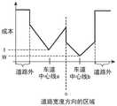
图6是示出当对车辆正在行驶的车道和相邻车道设定相同成本时的道路宽度方向的区域与成本之间的关系的曲线图。6 is a graph showing the relationship between the area in the road width direction and the cost when the same cost is set for the lane in which the vehicle is traveling and the adjacent lane.
图7是示出当将比车辆正在行驶的车道要高的成本设定于相邻车道时的道路宽度方向的区域与成本之间的关系的曲线图。7 is a graph showing the relationship between the area in the road width direction and the cost when a cost higher than the lane in which the vehicle is traveling is set to the adjacent lane.
图8是示出当在相邻车道中设定了最大成本时的道路宽度方向的区域与成本之间的关系的曲线图。FIG. 8 is a graph showing the relationship between the area in the road width direction and the cost when the maximum cost is set in the adjacent lane.
图9是示出当将比车辆正在行驶的车道要低的成本设定于相邻车道时的道路宽度方向的区域与成本之间的关系的曲线图。9 is a graph showing the relationship between the area in the road width direction and the cost when a cost lower than the lane in which the vehicle is traveling is set to an adjacent lane.
图10是示出车辆的预测路径候补的图。FIG. 10 is a diagram showing predicted route candidates of the vehicle.
图11是表示实施方式1的预测路径设定部的动作的流程图。11 is a flowchart showing the operation of the predicted route setting unit according to the first embodiment.
图12是表示预测路径候补的生成处理的概要的图。FIG. 12 is a diagram showing an outline of a process for generating predicted route candidates.
图13是示出从选择出的时刻步长的节点分岔为多个的预测路径候补的图。FIG. 13 is a diagram showing a plurality of predicted path candidates branched from a node of a selected time step.
图14是示出从选择出的多个时刻步长各自的节点分岔为多个的预测路径候补的图。FIG. 14 is a diagram showing a plurality of predicted path candidates branched from each node of a plurality of selected time steps.
图15是表示本发明的实施方式2所涉及的路径预测装置的功能结构的框图。15 is a block diagram showing a functional configuration of a path prediction apparatus according to
图16是表示在具有分岔路的道路上行驶的车辆、前车、前前车以及相邻车道车辆的位置关系的图。16 is a diagram showing the positional relationship between a vehicle traveling on a road having a branch road, a preceding vehicle, a preceding vehicle, and a vehicle in an adjacent lane.
具体实施方式Detailed ways
下面,为了更详细地说明本发明,根据附图,对用于实施本发明的方式进行说明。Hereinafter, in order to explain this invention in more detail, the form for implementing this invention is demonstrated based on drawing.
实施方式1
图1是表示本发明的实施方式1中的硬件结构的框图。实施方式1的车辆例如如图1所示,包括包含各种传感器的传感器组1、控制ECU(Electronic Control Unit:电子控制单元)2、路径预测装置3和无线通信装置4。控制ECU2能够基于由传感器组1检测出的信息,控制车辆内部的控制对象的硬件。FIG. 1 is a block diagram showing a hardware configuration in
传感器组1构成为包含检测与存在于车辆周边的车辆或行人等移动体的状态有关的信息的传感器、以及检测与车辆的状态有关的信息的传感器。在传感器组1中,包含车速传感器1a、转向角传感器1b、加速器传感器1c、制动器传感器1d、加速度传感器1e、角速度传感器1f、GPS(Global Positioning System:全球定位系统)装置1g、车外照相机1h、以及车外传感器1i。The
此外,与检测对象物的状态有关的信息是至少包含检测对象物的位置以及移动速度的信息,如果检测对象物是车辆,则也可以包含加速度、方向盘的操作量、加速器的操作量、制动器的操作量这样的信息。In addition, the information on the state of the detection target is information including at least the position and moving speed of the detection target, and if the detection target is a vehicle, it may also include acceleration, steering wheel operation amount, accelerator operation amount, and brake operation amount. information such as the amount of operations.
车速传感器1a是检测车辆的速度的传感器,将与车轮速度对应的电信号(车速脉冲)输出至控制ECU2。The
转向角传感器1b是检测车辆的转向角的传感器,将与转向角相应的电信号输出到控制ECU2。The steering angle sensor 1b is a sensor that detects the steering angle of the vehicle, and outputs an electric signal corresponding to the steering angle to the
加速器传感器1c是检测车辆的加速器的开度、即加速踏板的操作量的传感器。加速踏板的操作量信息从加速器传感器1c输出到控制ECU2。The accelerator sensor 1c is a sensor that detects the opening degree of the accelerator of the vehicle, that is, the operation amount of the accelerator pedal. The operation amount information of the accelerator pedal is output to the
制动器传感器1d是检测制动踏板的操作量的传感器,将制动踏板的操作量信息输出到控制ECU2。The brake sensor 1d is a sensor that detects the operation amount of the brake pedal, and outputs the operation amount information of the brake pedal to the
加速度传感器1e是检测车辆的加速度的传感器,例如由3轴加速度传感器构成。由加速度传感器1e检测出的车辆的加速度信息被输出到控制ECU2。The acceleration sensor 1e is a sensor that detects the acceleration of the vehicle, and is constituted by, for example, a three-axis acceleration sensor. The acceleration information of the vehicle detected by the acceleration sensor 1e is output to the
角速度传感器1f是检测车辆的角速度(陀螺仪)的传感器。The angular velocity sensor 1f is a sensor that detects the angular velocity (gyroscope) of the vehicle.
由角速度传感器1f检测出的角速度信息被输出至控制ECU2。The angular velocity information detected by the angular velocity sensor 1f is output to the
控制ECU2能够基于由角速度传感器1f检测出的角速度信息来检测车辆的转弯速度。The
GPS装置1g利用GPS卫星发送的电波来检测车辆的位置。The
由GPS装置1g检测出的车辆的位置坐标(纬度经度)被输出至控制ECU2。另外,GPS装置1g例如也可以是组合了IMU(Inertial Measurement Unit:惯性测量单元)的装置。利用GPS装置1g检测车辆的位置,利用IMU检测车辆的姿态倾斜度。The position coordinates (latitude and longitude) of the vehicle detected by the
车外照相机1h是拍摄车辆外部的照相机,例如通过光学照相机、红外线照相机来实现。由车外照相机1h拍摄的拍摄图像被输出到控制ECU2。控制ECU2基于从车外照相机1h输入的拍摄图像,执行车辆周边的行人、车辆、障碍物这样的检测对象物的检测以及识别。The exterior camera 1h is a camera for photographing the exterior of the vehicle, and is realized by, for example, an optical camera or an infrared camera. The captured image captured by the outside camera 1h is output to the
另外,控制ECU2能够根据车外照相机1h的拍摄图像来识别车辆正在行驶的道路的白线。In addition, the
车外传感器1i是检测车辆周边存在的车辆或行人这样的移动体的位置和移动速度的传感器,例如,可以通过毫米波雷达、激光雷达来实现。车外传感器1i将移动体的检测信息输出到控制ECU2。The exterior sensor 1i is a sensor that detects the position and moving speed of a moving object such as a vehicle or a pedestrian existing around the vehicle, and can be realized by, for example, a millimeter-wave radar or a lidar. The vehicle exterior sensor 1i outputs the detection information of a moving body to the control ECU2.
控制ECU2基于从车外传感器1i输入的移动体的检测信息,检测移动体的位置以及车辆与移动体的距离。车辆与车辆周边的移动体的距离以及移动体的位置检测可以由控制ECU2进行,也可以由车外传感器1i自身进行并向控制ECU2输出检测结果,也可以由路径预测装置3进行。The
控制ECU2具有控制车辆整体的功能。如图1所示,控制ECU2具备处理器2a、ROM(Read Only Memory:只读存储器)2b、RAM(Random Access Memory:随机存取存储器)2c。The
处理器2a是在控制ECU2中进行各种计算处理的计算处理电路,是被称为处理器、计算处理电路、电气电路、控制器等的硬件。处理器2a由一个或两个以上的计算处理电路的集合构成。处理器2a可以从ROM2b读出程序,将它们在RAM2c上展开并执行计算处理。The
ROM2b是存储一个以上的程序的非易失性存储装置。The
RAM2c是处理器2a用作为程序和各种信息的展开区域的易失性存储装置。The RAM 2c is a volatile storage device used by the
ROM2b及RAM2c例如由半导体存储装置构成,也可以称为存储器。The
作为存储有处理器2a执行的程序的存储装置例示了ROM2b,但上述存储装置并不限定于此。例如,上述存储装置也可以是HDD(Hard Disk Drive:硬盘驱动器)、SSD(SolidState Drive:固态驱动器)这样的被称为存储设备的非易失性大容量存储装置。The
另外,也可以将包含存储设备的存储装置统称为存储器。In addition, a storage device including a storage device may be collectively referred to as a memory.
这一点在后述的路径预测装置3中也是同样的。This is also the same in the
发动机2d是驱动车辆的动力源,产生使车轮旋转的动力。发动机2d也能够根据来自控制ECU2的指示进行动作。The engine 2d is a power source for driving the vehicle, and generates power for rotating the wheels. The engine 2d can also be operated in accordance with an instruction from the
变速器2e将在发动机2d中产生的动力传递到车轮。变速器2e基于来自控制ECU2的指示来变更齿轮,由此能够变更传递至车轮的转矩。The
制动致动器2f是使车辆的制动器(减速器)动作的机构,能够根据控制ECU2的指示使制动器动作来使车辆减速。The brake actuator 2f is a mechanism for actuating the brake (reducer) of the vehicle, and can decelerate the vehicle by actuating the brake in accordance with an instruction from the
转向致动器2g是使车辆的转向器(转向装置)动作的机构,能够根据控制ECU2的指示来控制转向器,从而控制车辆的行进方向。The
路径预测装置3是搭载于车辆并依次预测车辆应行驶的数秒后的每个预测时刻的预测路径的装置,与控制ECU2同样地,具备处理器3a、ROM3b以及RAM3c。The
处理器3a是在路径预测装置3中进行各种计算处理的计算处理电路,是被称为处理器、计算处理电路、电气电路或控制器的硬件。处理器3a由一个或两个以上的计算处理电路的集合构成。处理器3a可以从ROM3b读出程序,将它们在RAM3c上展开来执行计算处理。The
无线通信装置4是与外部装置进行无线通信的通信装置。无线通信装置4进行车车间通信、路车间通信、或与以智能手机为代表的便携通信终端的通信。在无线通信装置4中,发送部4b经由天线4a向外部装置发送无线信号,接收部4c经由天线4a从外部装置接收无线信号。The wireless communication device 4 is a communication device that performs wireless communication with an external device. The wireless communication device 4 performs vehicle-to-vehicle communication, road-to-vehicle communication, or communication with a portable communication terminal such as a smartphone. In the wireless communication device 4, the transmitting
另外,在图1中,示出了搭载于车辆的路径预测装置3,但实施方式1并不限定于该结构。In addition, in FIG. 1, although the
例如,路径预测装置3也可以是能够经由无线通信装置4与车辆的控制ECU2进行无线通信的服务器装置所具备的构成要素。For example, the
在该情况下,车辆的路径预测所需要的信息经由无线通信装置4从车辆侧向服务器装置发送,服务器装置所具备的路径预测装置3基于从车辆侧接收到的上述信息来决定车辆的预测路径。In this case, the information necessary for the prediction of the route of the vehicle is transmitted from the vehicle side to the server device via the wireless communication device 4, and the
车辆的预测路径信息从服务器装置侧发送到车辆侧,车辆的控制ECU2将从服务器装置侧接收到的预测路径信息所表示的路径设定为车辆的路径。The predicted route information of the vehicle is transmitted from the server device side to the vehicle side, and the
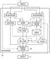
图2是表示路径预测装置3的功能结构的框图。如图2所示,路径预测装置3具备第1信息获取部30、第2信息获取部31、检测部32、预测处理部33、目标路径设定部34、地图数据库(以下,记载为地图DB)35、第1计算部36、第2计算部37、决定部38以及预测路径设定部39。FIG. 2 is a block diagram showing the functional configuration of the
第1信息获取部30获取与存在于车辆周边的移动体的状态有关的信息。与移动体的状态相关的信息是包含存在于车辆周边的车辆或行人的位置以及移动速度在内的信息,例如从控制ECU2获取。The first
此外,第1信息获取部30也可以从传感器组1直接获取与存在于车辆周边的移动体的状态有关的信息。In addition, the first
第2信息获取部31获取与车辆的状态有关的信息。The second
与车辆的状态有关的信息是包含车辆的位置和移动速度的信息,例如从控制ECU2获取。The information about the state of the vehicle is information including the position and moving speed of the vehicle, and is acquired from the
此外,第2信息获取部31也可以从传感器组1直接获取与车辆的状态有关的信息。In addition, the second
检测部32基于由第1信息获取部30获取的与移动体的状态相关的信息、以及由目标路径设定部34设定的目标路径信息,检测与正在目标路径上行驶的车辆的前车以及前前车各自的状态相关的信息。The
例如,检测部32从存在于车辆周边的移动体中认定前车,从与移动体的状态有关的信息中,检测与认定的前车的状态有关的信息。For example, the
同样地,检测部32从存在于车辆周边的移动体中认定为前前车,从与移动体的状态有关的信息中,检测与所认定的前前车的状态有关的信息。Similarly, the
预测处理部33基于由第1信息获取部获取的与移动体的状态相关的信息,针对预测时刻的每个时刻步长来计算移动体的预测位置信息。The
预测时刻是指从当前时刻开始依次设定的时刻,例如是从当前时刻开始以一定的时间间隔依次设定的时刻。The predicted time refers to the time set sequentially from the current time, for example, the time set sequentially at a certain time interval from the current time.
预测处理部33基于与移动体的状态相关的信息,针对直到预测时刻为止的每个时刻步长来计算移动体的预测位置。The
例如,预测处理部33假定移动体进行等速直线运动,基于当前时刻的移动体的位置以及速度,计算移动体的预测位置。For example, the
此外,预测处理部33可以基于当前时刻的移动体的位置、速度和加速度来计算移动体的预测位置。Further, the
进一步地,预测处理部33可以基于从地图DB35读取的道路信息来计算车辆正在行驶的道路的每条车道的移动体的预测位置。Further, the
目标路径设定部34基于由第2信息获取部31获取的与车辆的状态相关的信息和地图信息,设定到车辆的最终目的地为止的目标路径。The target
例如,目标路径设定部34基于与车辆的状态相关的信息所包含的车辆的当前位置、包含该位置的地图信息以及预先设定的最终目的地,搜索从车辆的当前位置到最终目的地的目标路径,并将目标路径信息设定于控制ECU2。For example, the target
目标路径信息从目标路径设定部34输出到检测部32和第1计算部36。目标路径信息中,在从车辆的当前位置到最终目的地的路径的基础上,还包含路径上的车道各自的推荐速度、以及在包含分岔路的情况下从其引导地点到分岔路的距离(以下记载为分岔到达距离)。The target route information is output from the target
地图DB35是登录有地图信息的数据库。地图信息例如包含道路的车道数量、车道的位置信息、道路的结构、每条车道的推荐速度。The
在车道的位置信息中,包含构成车道的中心线的点群的各自的绝对坐标值(例如,纬度经度)。道路的结构是表示弯道的位置、停止线的位置、信号灯的位置的信息。The position information of the lane includes absolute coordinate values (for example, latitude and longitude) of each point group constituting the center line of the lane. The structure of the road is information indicating the position of the curve, the position of the stop line, and the position of the signal light.
第1计算部36基于由第2信息获取部31获取的与车辆状态有关的信息、由目标路径设定部34设定的目标路径信息、以及由检测部32获取的与前车及前前车各自的状态有关的信息,来计算在目标路径上行驶的车辆超越前车时的余量时间。The
例如,第1计算部36在目标路径中包含分岔路的情况下,将车辆到达为止的分岔到达时间和确保在前车与前前车之间车辆能够进入的空间的空间确保时间中的较短的一方的时间决定为上限值。For example, when the target route includes a branch road, the
接着,第1计算部36将车辆超越前车且进入前车与前前车之间为止所需的时间决定为下限值。Next, the
然后,第1计算部36计算这样决定的上限值和下限值之间的差分以作为车辆超越前车时的余量时间。Then, the
第2计算部37根据上述余量时间的长度来计算车辆正在行驶的车道和相邻车道各自的成本权重,并进行加权。The
例如,第2计算部37将车辆超越前车所需的标准时间与余量时间进行比较,在两者一致的情况下,以使得车辆正在行驶的车道的成本与相邻车道的成本相同的方式计算两者的权重并进行加权。For example, the
第2计算部37在余量时间比标准时间短的情况下,以使得车辆正在行驶的车道的成本低于相邻车道的成本的方式计算两者的权重并进行加权。When the remaining time is shorter than the standard time, the
第2计算部37在余量时间比标准时间长的情况下,以使得车辆正在行驶的车道的成本高于相邻车道的成本的方式计算两者的权重并进行加权。When the remaining time is longer than the standard time, the
决定部38针对每个预测时刻决定作为在预测时刻的车辆位置的中间目的地。例如,决定部38基于由第2信息获取部31获取的车辆的位置和速度、以及地图信息,假定车辆以匀速移动直至到达预测时刻,按照从当前时刻起依次设定的每个预测时刻来决定中间目的地的位置信息。The
预测路径设定部39基于由第2计算部37加权后的车道的成本信息、由决定部38决定的中间目的地的位置信息、以及由预测处理部33计算出的移动体的预测位置信息,根据车道的成本信息来生成多个预测路径候补。The predicted
例如,预测路径设定部39将开始对到预测时刻为止的时间进行计时的时刻的与车辆的状态有关的信息(位置、速度、加速度以及转向角)设定为与初始状态有关的信息。For example, the predicted
接着,预测路径设定部39基于与初始状态有关的信息,将从当前时刻到下一个时刻步长为止车辆能够到达的位置设定为下一个时刻步长的车辆的预测位置候补。此时,预测路径设定部39将从当前时刻到下一个时刻步长为止车辆能够到达的位置中、处于设定了低成本的车道侧的位置优先作为预测位置候补。Next, the predicted
预测路径设定部39按照下一个时刻步长的每个预测位置候补,预测车辆的速度、加速度以及转向角,并设定为各自的车辆的状态。The predicted
接着,预测路径设定部39基于在下一个时刻步长的与车辆状态相关的信息,将从下一个时刻步长到再下一个时刻步长为止车辆能够到达的位置设定为再下一个时刻步长的车辆的预测位置候补。Next, the predicted
然后,预测路径设定部39按照再下一个时刻步长的每个预测位置候补,预测车辆的速度、加速度以及转向角,并设定为各自的车辆的状态。Then, the predicted
通过重复这样的处理,预测路径设定部39生成在避开到预测时刻为止存在的移动体的同时使车辆去往中间目的地的多个预测路径候补。By repeating such processing, the predicted
预测路径设定部39将从多个预测路径候补中选择的预测路径设定为每个预测时刻的车辆的路径。例如,预测路径设定部39选择所有预测位置的成本的总和最小的预测路径候补作为车辆的预测路径。The predicted
由预测路径设定部39按每个预测时刻选择的预测路径信息被输出到控制ECU2。控制ECU2根据从预测路径设定部39输入的预测路径信息来控制车辆的动作,由此使车辆沿着预测路径行驶。The predicted route information selected by the predicted
另外,在图2中,示出了路径预测装置3具备第1信息获取部30、第2信息获取部31、检测部32、预测处理部33、目标路径设定部34、地图DB35、第1计算部36、第2计算部37、决定部38以及预测路径设定部39的结构,但实施方式1并不限定于该结构。In addition, FIG. 2 shows that the
例如,目标路径设定部34以及地图DB35可以是能够经由无线通信装置4进行通信的外部装置所具备的构成要素,第1信息获取部30、第2信息获取部31以及检测部32可以是控制ECU2所具备的构成要素。For example, the target
在该情况下,路径预测装置3经由无线通信装置4从外部装置接收地图信息以及目标路径信息,从控制ECU2获取与车辆周边的状态相关的信息、与车辆的状态相关的信息、与前车的状态相关的信息以及与前前车的状态相关的信息。In this case, the
即,在实施方式1中,路径预测装置3也可以是不具备第1信息获取部30、第2信息获取部31、检测部32、目标路径设定部34以及地图DB35的结构。That is, in
接着对动作进行说明。Next, the operation will be described.
图3是表示实施方式1所涉及的路径预测方法的流程图。FIG. 3 is a flowchart showing a route prediction method according to
首先,第1信息获取部30获取与存在于车辆周边的移动体的状态相关的信息(步骤ST1)。与移动体的状态有关的信息是包括存在于车辆周边的车辆或行人的位置以及移动速度的信息。First, the first
例如,在通过传感器组1中的传感器检测出分别不同的移动体的状态的情况下,第1信息获取部30获取与通过各自的传感器检测出的移动体的状态相关的信息。For example, when the states of the moving objects that are different from each other are detected by the sensors in the
当通过传感器组1中的多个传感器重复检测到相同移动体的状态时,第1信息获取部30进行考虑了这些传感器的精度的加权平均,将这些检测信息汇总为一个而作为与最终的移动体的状态相关的信息。When the state of the same moving body is repeatedly detected by a plurality of sensors in the
由此,能够得到移动体的状态的高精度检测信息。Thereby, highly accurate detection information of the state of the moving body can be obtained.
此外,与移动体的状态相关的信息的上述加权平均在车辆周边的移动体的追尾处理中由控制ECU2执行。在该情况下,第1信息获取部30也可以获取由控制ECU2计算出的加权平均值作为与移动体的状态相关的信息。In addition, the above-described weighted average of the information related to the state of the moving body is executed by the
接着,第2信息获取部31获取与车辆的状态有关的信息(步骤ST2)。与车辆的状态有关的信息是包含车辆的位置以及移动速度的信息。Next, the second
例如,在通过传感器组1中的传感器检测出分别不同的车辆的状态的情况下,第1信息获取部30获取与通过各自的传感器检测出的车辆的状态相关的信息。当通过传感器组1中的多个传感器重复检测到车辆的状态时,第2信息获取部31进行考虑了这些传感器的精度的加权平均,将这些检测信息汇总为一个而作为与最终的车辆的状态相关的信息。由此,能够得到车辆的状态的高精度检测信息。For example, when different vehicle states are detected by the sensors in the
目标路径设定部34设定到达车辆的最终目的地的目标路径(步骤ST3)。例如,目标路径设定部34基于包含在与车辆的状态相关的信息中的车辆的当前位置、从地图DB35读出的包含车辆的当前位置的地图信息以及预先设定的最终目的地,来搜索从车辆的当前位置到最终目的地的目标路径。The target
搜索结果的目标路径信息被输出到检测部32和第1计算部36,进而被设定到控制ECU2。The target route information of the search result is output to the
另外,从步骤ST1到步骤ST3的各个处理在处理的顺序上可以前后进行,也可以同时执行这些处理。In addition, each process from step ST1 to step ST3 may be performed successively in the order of processing, or these processes may be performed simultaneously.
检测部32检测与在目标路径上行驶的车辆的前车以及前前车的各自的状态相关的信息(步骤ST4)。The
例如,检测部32将存在于车辆周边的移动体中、位于目标路径上的前方且在距离车辆最近的位置移动的移动体认定为前车。检测部32从由第1信息获取部30获取的与移动体的状态有关的信息中,检测与认定的前车的状态有关的信息。For example, the
与前车的状态相关的信息是包含前车的当前位置以及车速(沿着目标路径的方向的车速)的信息。The information on the state of the preceding vehicle is information including the current position of the preceding vehicle and the vehicle speed (vehicle speed in the direction along the target route).
同样,检测部32将存在于车辆周边的移动体中、位于目标路径上的前方且在距离车辆第2近的位置移动的移动体认定为前前车。Similarly, the
检测部32从由第1信息获取部30获取的与移动体的状态有关的信息中,检测与认定的前前车的状态有关的信息。The
位于目标路径上的前方且在距离车辆第2近的位置移动的移动体也是位于前车的前方且在距离前车最近的位置移动的移动体。The moving body that is located ahead of the target path and that moves at the second closest position to the vehicle is also a moving body that is located in front of the preceding vehicle and moves at the closest position to the preceding vehicle.
与前前车的状态相关的信息是包含前前车的当前位置以及车速(沿着目标路径的方向的车速)的信息。The information about the state of the preceding vehicle is information including the current position of the preceding vehicle and the vehicle speed (vehicle speed in the direction along the target route).
接下来,预测处理部33基于由第1信息获取部获取的与移动体的状态相关的信息,按照到预测时刻为止的每个时刻步长来计算移动体的预测位置信息(步骤ST5)。预测时刻是从当前时刻起依次设定的时刻,例如是从当前时刻起每隔数秒左右的一定的时间间隔依次设定的时刻。Next, the
例如,预测处理部33假定移动体进行等速直线运动直至到达该预测时刻为止,并根据当前时刻的移动体的位置以及速度来计算移动体的预测位置。For example, the
接下来,第1计算部36计算车辆超越前车时的余量时间(步骤ST6)。以下,以目标路径中包含分岔路的情况为例进行说明。Next, the
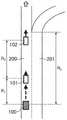
图4是表示在具有分岔路的道路上行驶的车辆100、前车101以及前前车102的位置关系的图。FIG. 4 is a diagram showing the positional relationship between the
在图4中,车辆100是具有图1所示的构成要素的车辆,搭载有路径预测装置3。车辆100正在行驶的车道200是去往最终目的地的车道,相邻车道201是去往分岔路的车道。前车101是在车道200上在车辆100的前方行驶的车辆,前前车102是在车道200上在前车101的前方行驶的车辆。In FIG. 4 , a
第1计算部36将包含在目标路径信息中的分岔到达距离Rb和包含在与车辆100的状态有关的信息中的车辆100的速度Vego代入下述式(1),以计算车辆100到达分岔路为止的时间即分岔到达时间Tlim。The
第1计算部36通过将车辆100与前车101之间的车间距离R1、车辆100与前车101之间的间隔距离THR1、前车101的速度Vp1代入下述式(2),来计算直至车辆100完成前车101的超越所需的时间。The
使用下述式(2)计算出的上述时间是车辆100完成前车101的超越为止所需的时间、即车辆100超越前车101之后进入前车101与前前车102之间为止所需的时间。The above-mentioned time calculated using the following formula (2) is the time required for the
在实施方式1中,该时间被设为下限值Tlower。In
而且,与前车101的间隔距离THR1是在车辆100超越前车101时两者最接近的距离,是根据经验得到的值。Further, the distance THR1 from the preceding
速度Vego是车辆100在沿着目标路径的方向上的速度。速度Vp1是前车101在沿着目标路径的方向上的速度。The speedVego is the speed of the


第1计算部36通过将前车101与前前车102之间的车间距离R2、前车101与前前车102之间的车间距离THR2、前车101的速度Vp1、前前车102的速度Vp2代入下述式(3),来计算空间确保时间Tspace。The
在此,车间距离THR2是为了使超越前车101的车辆100进入前车101与前前车102之间所需要的前车101与前前车102之间的车间距离。车间距离THR2例如是对车辆100的全长加上余裕长度而得到的值,是根据经验得到的值。Here, the inter-vehicle distance THR2 is the inter-vehicle distance between the preceding
空间确保时间Tspace是确保在前车101与前前车102之间车辆100能够进入的空间的时间。The space securing time Tspace is a time for securing a space between the preceding

第1计算部36根据下述式(4)将分岔到达时间Tlim和空间确保时间Tspace中较短一方的时间决定为上限值Tupper。The
这样决定下限值Tlower和上限值Tupper后,第1计算部36根据下述式(5)计算上限值Tupper与下限值Tlower之间的差分作为车辆100超越前车101时的余量时间Tmrgn。After the lower limit value Tlower and the upper limit value Tupper are determined in this way, the
由于第1计算部36在假定车辆100以一定速度Vego行驶的情况下计算余量时间Tmrgn,因此能够通过简单计算来求得车辆100超越前车101时的余量时间Tmrgn。Since the
Tupper=min(Tlim,Tspace) (4)Tupper = min(Tlim , Tspace ) (4)
Tmrgn=Tupper-Tlower (5)Tmrgn =Tupper -Tlower (5)
接着,第2计算部37根据余量时间Tmrgn的长度来计算车辆100正在行驶的车道和相邻车道的各自的成本的权重信息(步骤ST7)。Next, the
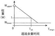
图5是示出车道的成本的权重W与超越的余量时间Tmrgn之间的关系的曲线图。在图5中,权重Wupper是赋予车道的成本的权重的最大值,权重Wlower是赋予车道的成本的权重的最小值。标准时间Tot是车辆100超越前车101通常所需要的时间,例如,也可以设想车辆100在4秒内变更车道至相邻车道201之后超越前车101,在4秒内返回车道200,从而设定8秒。FIG. 5 is a graph showing the relationship between the weight W of the cost of the lane and the overrun margin time Tmrgn . In FIG. 5 , the weight Wupper is the maximum value of the weights given to the cost of the lane, and the weight Wlower is the minimum value of the weights given to the cost of the lane. The standard time Tot is the time usually required for the
例如,第2计算部37将标准时间Tot与余量时间Tmrgn进行比较,在两者一致的情况下,以使得车辆100正在行驶的车道200的成本与相邻车道201的成本相同的方式计算两者的权重并进行加权。For example, the
另外,在图5所示的示例中,由于对车道200和相邻车道201初始设定相同标准的成本,因此作为两者的权重而设定W=1。In addition, in the example shown in FIG. 5, since the cost of the same standard is initially set to the
第2计算部37在余量时间Tmrgn比标准时间Tot短的情况下,以使得车辆100正在行驶的车道200的成本低于相邻车道201的成本的方式计算两者的权重W并进行加权。When the remaining time Tmrgn is shorter than the standard time Tot , the
例如,在余量时间Tmrgn为0或负值的情况下,第2计算部37可以将无限大或极大的值设定为分配给相邻车道201的成本的Wupper,使得不选择车辆100将超越前车101的预测路径。For example, when the remaining time Tmrgn is 0 or a negative value, the
第2计算部37在余量时间Tmrgn比标准时间Tot长的情况下,以使得车辆100正在行驶的车道200的成本高于相邻车道201的成本的方式计算两者的权重W并进行加权。When the residual time Tmrgn is longer than the standard time Tot , the
例如,在余量时间Tmrgn与标准时间Tot相比足够长的情况下,第2计算部37对相邻车道201的成本赋予权重Wlower,以使得容易选择车辆100向相邻车道201变更车道后超越前车101的预测路径。在图5中,权重Wupper和权重Wlower也可以由用户适当设定。For example, when the residual time Tmrgn is sufficiently longer than the standard time Tot , the
图6是示出当对车辆100正在行驶的车道200和相邻车道201设定了相同成本时的道路宽度方向的区域与成本之间的关系的曲线图。在图6中,对于车辆100正在行驶的车道200的中心线a以及相邻车道201的中心线b的各自的成本,作为标准的成本而设定有相同的值。FIG. 6 is a graph showing the relationship between the area in the road width direction and the cost when the same cost is set for the
车道200的成本是对设定在车道200的中心线a上的标准成本将与节点302和车道200的中心线a的欧几里得距离相对应的成本累计而得到的。The cost of the
同样,相邻车道201的成本是对设定在相邻车道201的中心线b上的标准成本将与节点302和相邻车道201的中心线b的欧几里得距离相对应的成本累计而得到的。Likewise, the cost of the
第2计算部37对车道200的成本和相邻车道201的成本设置权重W=1。The
由此,由于每条车道在中心线成本最低,随着远离车道的中心线,成本变高,因此难以选择从车道的中心线脱离的预测路径候补。另外,如图6所示,在道路外设定成本的最大值,因此不选择车辆100在道路外行驶的预测路径候补301。Therefore, since the cost per lane is the lowest at the center line, and the cost increases as the distance from the center line of the lane increases, it is difficult to select a predicted route candidate that deviates from the center line of the lane. In addition, as shown in FIG. 6, since the maximum value of the cost is set outside the road, the predicted
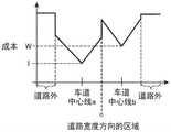
图7是示出当在相邻车道201中设定了比车辆100正在行驶的车道200高的成本时的道路宽度方向的区域与成本之间的关系的曲线图。在图7中,分割线c是车道200与相邻车道201之间的边界线。FIG. 7 is a graph showing the relationship between the area in the road width direction and the cost when a higher cost is set in the
第2计算部37在余量时间Tmrgn比标准时间Tot短的情况下,以使得车道200的成本小于相邻车道201的成本的方式计算两者的权重W并进行加权。此时,由于以分割线c为界,对相邻车道201的成本进行加权累计,如图7所示,相邻车道201的成本与车道200相比,相对上升。由此,车辆100在相邻车道201行驶的预测路径候补301难以被选择。When the remaining time Tmrgn is shorter than the standard time Tot , the
图8是示出当对相邻车道201设定了最大成本时道路宽度方向的区域与成本之间的关系的曲线图。在图8中,分割线c与图7同样,是车道200与相邻车道201之间的边界线。FIG. 8 is a graph showing the relationship between the area in the road width direction and the cost when the maximum cost is set for the
在余量时间Tmrgn为0或负值的情况下,第2计算部37对相邻车道201的成本累计权重的最大值Wupper,以使得不选择车辆100向相邻车道201进行车道变更的预测路径。由此,在相邻车道201中,与道路外同样地设定成本的最大值,因此不选择车辆100在相邻车道201中行驶的预测路径候补301。When the remaining time Tmrgn is 0 or a negative value, the
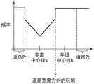
图9是示出当在相邻车道201中设定了比车辆100正在行驶的车道200低的成本时的道路宽度方向的区域与成本之间的关系的曲线图。在图9中,分割线c与图7同样,是车道200与相邻车道201之间的边界线。9 is a graph showing the relationship between the area in the road width direction and the cost when a lower cost than the
在余量时间Tmrgn比标准时间Tot长的情况下,第2计算部37对相邻车道201的成本累计权重Wlower,以使得容易选择车辆100向相邻车道201变更车道的预测路径。When the remaining time Tmrgn is longer than the standard time Tot , the
由此,如图9所示,相邻车道201的成本与车道200相比相对下降,因此容易选择车辆100在相邻车道201行驶的预测路径候补301。As a result, as shown in FIG. 9 , the cost of the
此外,第2计算部37可以计算针对由预测路径设定部39预测出的每个时刻步长的车辆100的预测位置的成本。Further, the
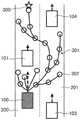
图10是表示车辆100的预测路径候补的图,表示了由预测路径设定部39生成的从车辆100的当前位置到中间目的地300的多个预测路径候补。在图10中,作为预测路径候补301,记载有跟随前车101的预测路径候补以及在避开在相邻车道201上行驶的车辆103、104的同时去往中间目的地300的预测路径候补301。FIG. 10 is a diagram showing predicted route candidates of the
如图10所示,预测路径候补301是通过用链路连接设定在每个时刻步长的车辆100的预测位置上的各个节点302而形成的。As shown in FIG. 10 , the predicted
此外,在节点302中设定有与每个预测位置的车辆100的状态有关的信息。以下,为了方便,将车辆100的预测位置称为节点302。In addition, information about the state of the
第2计算部37也可以随着在多个预测路径候补301中的、成为路径的最终端的节点302或者最接近中间目的地300的节点302越接近中间目的地300,设定越低的成本。The
另外,第2计算部37也可以随着多个预测路径候补301中的节点302越接近车道的中心线,设定越低的成本。In addition, the
这样,通过对节点302设定成本,优先选择所有节点302的成本总和低的预测路径候补301,从而容易选择不脱离车道的预测路径候补301。In this way, by setting the cost to the
第2计算部37可以随着预测路径候补301的各个节点302中包含的车辆100的预测速度越接近推荐速度,设定越低的成本。The
这样,通过对节点302设定成本,优先选择所有节点302的成本总和低的预测路径候补301,从而容易选择车辆100的速度变动少的预测路径候补301。In this way, by setting the cost to the
另外,第2计算部37也可以随着节点302越接近移动体的预测位置,设定越高的成本。In addition, the
这样,通过对节点302设定成本,优先选择所有节点302的成本总和低的预测路径候补301,从而容易选择车辆100避开移动体的预测路径候补301。By setting the cost to the
第2计算部37可以组合针对节点302的成本设定。The
例如,第2计算部37在构成预测路径候补301的多个节点302中,对接近车道的中心线的节点302设定低成本,对车辆100的预测速度接近推荐速度的节点302设定低成本,对接近移动体的预测位置的节点302设定高成本。For example, the
返回至图3的说明。Return to the description of FIG. 3 .
在步骤ST8中,决定部38决定中间目的地300。In step ST8 , the
例如,确定部38假设车辆100匀速移动直至到达预测时刻,并基于车辆100的位置、速度以及地图信息,按照从当前时刻t起依次设定的每个预测时刻Tpre来决定中间目的地300的位置信息。For example, the
在步骤ST9中,预测路径设定部39根据车道的成本信息生成多个预测路径候补301,该多个预测路径候补301在避开到预测时刻为止存在的移动体的同时,使车辆100去往中间目的地300。预测路径设定部39将从多个预测路径候补301中选择出的预测路径设定为每个预测时刻的车辆100的路径。In step ST9, the predicted
例如,预测路径设定部39将按每个预测时刻选择的预测路径信息设定于控制ECU2。控制ECU2通过按照由预测路径设定部39设定的预测路径信息来控制车辆100的动作,从而使车辆100沿着预测路径行驶。For example, the predicted
接着对预测路径设定处理的详细情况进行说明。Next, the details of the predicted route setting process will be described.
图11是示出预测路径设定部39的动作的流程图,示出图3的步骤ST9的详细处理。FIG. 11 is a flowchart showing the operation of the predicted
预测路径设定部39设定车辆100的初始状态(步骤ST1a)。The predicted
车辆100的初始状态是开始预测时刻的计时的时刻的车辆100的状态(位置、速度、加速度以及转向角)。The initial state of the
图12是表示预测路径候补301的生成处理的概要的图,表示从当前的时刻t到预测时刻t+Tpre为止的车辆100的预测路径候补301。预测路径设定部39设定初始状态作为时刻t的车辆100的状态。FIG. 12 is a diagram showing an outline of the generation process of the predicted
预测路径设定部39执行预测时刻循环的处理(步骤ST2a)。The predicted
在预测时间循环中,预测在从当前时刻t至预测时间t+Tpre的每个时刻步长的车辆100的状态(步骤ST2a-1)。In the prediction time loop, the state of the
预测路径设定部39将从上一时刻步长tp,k-1到下一时刻步长tp,k车辆100能够到达的位置作为下一时刻步长tp,k的车辆100的预测位置候补。此时,预测路径设定部39将直到时刻步长tp,k为止车辆100能够到达的位置中、处于设定了低成本的车道侧的位置优先作为预测位置候补。The predicted
例如,如图12所示,预测路径设定部39对前一时刻步长tp,k-1中的车辆100的状态设定车辆控制值,并计算下一时刻步长tp,k中的车辆100的状态。For example, as shown in FIG. 12, the predicted
在假定车辆控制值是车辆100的加速度,并且车辆100的加速度遵循平均值μin和标准偏差σin的高斯分布的情况下,预测路径设定部39根据高斯分布的随机数计算在下一时刻步长tp,k中的车辆100的加速度。Under the assumption that the vehicle control value is the acceleration of the
对于平均值μin,可以设定在前一时刻步长tp,k-1中的车辆100的加速度,也可以设定为0。标准偏差σin作为参数也可以设定基于车辆性能的标准值。For the average value μin , the acceleration of the
车辆控制值除了车辆100的加速度之外,还有转向角、转向角变化率,但可以与上述同样地按照每个时刻步长进行设定。The vehicle control value includes the steering angle and the steering angle change rate in addition to the acceleration of the
预测路径设定部39按照每个时刻步长反复进行步骤ST2a的处理。由此,计算出每个时刻步长的车辆100的状态,生成图12所示的路径。预测路径设定部39将按照每个预测时刻循环而生成的上述路径追加到预测路径候补301中(步骤ST3a)。The predicted
以下,为了方便,有时将预测路径候补301称为树,将每个时刻步长的车辆100的预测位置称为节点。Hereinafter, for the sake of convenience, the predicted
另外,预测路径设定部39也可以按照每个时刻步长tp,k计算车辆100的N个状态(位置、速度、加速度、转向角等),并基于这些状态按照每个时刻步长tp,k设定N个节点302。如上所述,通过第2计算部37为N个节点302分别设定成本。In addition, the predicted
预测路径设定部39可以根据下述式(6),基于对节点302设定的成本来计算节点302的似然度。由此,预测路径设定部39也可以确定前一时刻步长tp,k-1中的N个节点302中似然度Li(k)高的节点302,并根据所确定的节点302生成下一时刻步长tp,k中的节点302。The predicted
在下述式(6)中,似然度Li(k)是通过将对N个节点302中的一个节点302设定的成本Cost(i)的倒数除以成本Cost(i)的倒数的N个之和来标准化而获得的值。In the following formula (6), the likelihood Li (k) is N obtained by dividing the inverse of the cost Cost(i) set to one

此外,可以如以下那样计算节点302的似然度Li(k)。In addition, the likelihood Li (k) of the
假设m个成本各自的误差遵循高斯分布,则误差q可以使用下述式(7)来计算。在下述式(7)中,s是由各个成本构成的矢量,∑是误差协方差矩阵。Assuming that the errors of each of the m costs follow a Gaussian distribution, the error q can be calculated using the following equation (7). In the following formula (7), s is a vector composed of the respective costs, and Σ is an error covariance matrix.

例如,假定与节点302和车道的中心线的距离对应的成本、与节点302和存在于车辆周边的移动体的距离对应的成本、以及与设定于节点302的车辆100的速度和推荐速度的差分值对应的成本。For example, it is assumed that the cost corresponding to the distance between the
由这些成本构成的矢量s能够由下述式(8)表示,误差协方差矩阵∑能够由下述式(9)表示。The vector s composed of these costs can be represented by the following equation (8), and the error covariance matrix Σ can be represented by the following equation (9).
节点302的似然度Li(k)可以利用下述式(10)来计算。The likelihood Li (k) of the
在下述式(8)中,W是对车道设定的成本的加权系数。In the following formula (8), W is a weighting coefficient of the cost set to the lane.
其中,如果节点302接近于车道200,则为W=1。Wherein, if the
Δdlane是节点302与车道的中心线之间的距离,Δdobstacle是节点302与存在于车辆周边的移动体之间的距离,ΔVnom是对节点302设定的车辆100的速度与推荐速度的差分值。Δdlane is the distance between the
在下述式(9)中,σego2是车辆100的位置的误差方差。In the following formula (9), σego2 is the error variance of the position of the
σobstacle2是存在于车辆周边的移动体的位置的误差方差。σobstacle2 is the error variance of the position of the moving body existing around the vehicle.
σV2是车辆100的速度的误差方差。σV2 is the error variance of the speed of the
另外,在下述式(9)中,为了简化,将误差协方差矩阵∑的非对角项设为0,但也可以计算相关分量而设定为非对角项。In the following formula (9), the off-diagonal terms of the error covariance matrix Σ are set to 0 for simplicity, but the off-diagonal terms may be calculated by calculating the correlation components.
误差协方差矩阵∑的各个要素的值能够基于车辆100的位置以及速度、对存在于车辆周边的移动体的位置以及速度进行检测的传感器的精度来设定。The value of each element of the error covariance matrix Σ can be set based on the position and speed of the
s=[W·Δdlane Δdobstacle ΔVnom] (8)s=[W·Δdlane Δdobstacle ΔVnom ] (8)


通过将车道的成本信息反映到节点302的似然度,在余量时间Tmrgn较长的情况下,由于在相邻车道201生成的节点302增加,因此车辆100在相邻车道201行驶的预测路径候补301增加,最终变得容易被选择。By reflecting the cost information of the lane to the likelihood of the
在余量时间Tmrgn较短的情况下,由于在车辆100当前行驶的车道200上生成的节点302增加,因此车辆100在车道200上行驶的预测路径候补301增加,从而最终容易被选择。When the remaining time Tmrgn is short, since the number of
返回至图11的说明。Return to the description of FIG. 11 .
预测路径设定部39确认在多个预测路径候补301中是否存在路径最终端的节点302被设定在距离中间目的地300的一定范围内的预测路径候补(步骤ST4a)。The predicted
在路径最终端的节点302处于距离中间目的地300的一定范围内时(步骤ST4a:是),预测路径设定部39从多个预测路径候补301中选择预测路径(步骤ST5a)。When the
例如,预测路径设定部39选择多个预测路径候补301中、节点302的似然度和最大的预测路径候补301作为预测路径。For example, the predicted
另外,预测路径设定部39也可以从多个预测路径候补301中选择对节点302设定的成本的总和最低的预测路径候补301。In addition, the predicted
此外,预测路径设定部39也可以利用节点302的似然度对N个预测路径候补301中的每个时刻步长的设定于节点302的车辆100的状态进行加权平均,由此将N个预测路径候补301合并为1个预测路径候补301。In addition, the predicted
控制ECU2通过按照由预测路径设定部39设定的预测路径信息来控制车辆100的动作,从而使车辆100沿着预测路径行驶。The
在路径最终端的节点302没有到达距离中间目的地300的一定范围内时(步骤ST4a:否),预测路由设定部39选择时刻步长(步骤ST6a)。图13是示出从选择的时刻步长tp,i中的节点302分岔为多个的预测路径候补301的图。When the
在步骤ST6a中,预测路径设定部39与上述同样地从多个预测路径候补301中选择1个预测路径候补301。In step ST6a, the predicted
然后,预测路径设定部39从所选择的预测路径候补301中选择节点302,并且选择所选择的节点302的时间步长tp,i。Then, the predicted
例如,可以选择似然度高于一定阈值的节点302,可以选择成本低于一定阈值的节点302,或者可以使用均匀随机数随机选择节点302。For example,
预测路径设定部39在选择时刻步长tp,i后,返回步骤ST1a的处理。此时,预测路径设定部39将时刻步长tp,i中的节点302作为车辆100的初始状态下的节点302,执行步骤ST1a至步骤ST3a的处理。The predicted
由此,生成由下述式(11)表示的、针对直到预测时间ΔTpre,i的每个时刻步长的节点302,并且生成由这些节点302构成的添加树301A。添加树301A的末端的节点302是时刻t+Tpre的节点302。Thereby,
ΔTpre,i=t+Tpre-tp,i (11)ΔTpre, i = t + Tpre - tp, i (11)
预测路径设定部39在时刻步长tp,i的节点302中生成与添加树301A连接的预测路径候补301时,重复上述处理,直至预测路径候补301的最终端的节点30 2到达距离中间目的地300的一定范围内。When the predicted
例如,如果分岔前的预测路径候补301中的节点302的总数是P1,并且添加树301A中的节点302的总数是P2,则预测路径设定部39从P1+P2个节点302中选择一个节点302,并且重复上述处理。For example, if the total number of
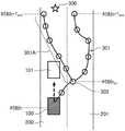
图14是示出从选择出的多个时刻步长各自的节点分岔为多个的预测路径候补301的图。在图14的例子中,通过预测路径设定部39生成与添加树301A以及添加树301A-1分别相连的预测路径候补301。当最终端的节点302到达距离中间目的地300的一定范围400内时,预测路径设定部39转移至图11的步骤ST5a的处理。FIG. 14 is a diagram showing a plurality of predicted
预测路径设定部39从分岔为多个的预测路径候补301中选择一个预测路径。例如,预测路径设定部39选择分岔为多个的预测路径候补301中最终端的节点302最接近中间目的地300的路径。The predicted
另外,预测路径设定部39也可以计算分岔为多个的预测路径候补301中分岔路径的各自的成本,选择这些成本最低的分岔路径作为预测路径。In addition, the predicted
分岔路径的成本也可以是对构成分岔路径的所有节点302设定的成本的总和。The cost of the bifurcated path may be the sum of the costs set for all the
例如,分岔路径中的第j个节点302可以通过下述式(12)计算。其中,αi(i=1,2,3)是决定分岔路径的各自的成本的比重的参数,也可以由用户任意设定。For example, the
Cost(j)=α1·W·Δdlane+α2·Δdobstacle+α3·ΔVnom (13)Cost(j)=α1 ·W·Δdlane +α2 ·Δdobstacle +α3 ·ΔVnom (13)
另外,说明了预测路径候补301的生成处理的一个例子,但是在生成预测路径候补301时,也可以使用迪杰斯特拉算法、A*算法这样的一般的路径生成方法。In addition, an example of the generation process of the predicted
另外,当最终端的节点302到达距离中间目的地300的一定范围400内时,结束生成预测路径候补301,但只要路径预测装置3的处理器3a的处理能力有余裕,也可以反复生成预测路径候补301。In addition, when the
在余量时间Tmrgn较短而无法由车辆100超越前车101的情况下,也可以设定为使中间目的地300跟随前车101。When the remaining time Tmrgn is short and the
例如,第1计算部36使用上述式(5)来计算余量时间Tmrgn,并且在余量时间Tmrgn为0或为负时将不能超越标记输出至决定部38。For example, the
决定部38在根据不能超越标记的值而识别出车辆100无法超越前车101这一情况时,将中间目的地300设定在处于车辆100正在行驶的车道200上、且不超越而能跟随前车101的位置。When recognizing that the
通过这样将中间目的地300变更为跟随前车101的位置,不会无用地生成超越用的预测路径候补301,能够降低路径预测装置3的运算负荷。By changing the
对车辆100以一定的加速度超越前车101的情况下的余量时间Tmrgn的计算方法进行说明。A method of calculating the remaining time Tmrgn when the
第1计算部36使用下述式(13)来计算分岔到达时间Tlim。The
接下来,第1计算部36使用下述式(14)来计算从车辆100以一定的加速度行驶并超越前车101起到进入前车101与前前车102之间为止所需要的时间即下限值Tlower。Next, the
接着,第1计算部36根据上述式(3)至上述式(5),使用分岔到达时间Tlim和下限值Tlower来计算超越的余量时间Tmrgn。Next, the
在下述式(13)和下述式(14)中,αego是车辆100的加速度(一定),Vego是车辆100的当前的速度,Vlim是车辆100正在行驶的道路的限制速度。由此,即使在车辆100加速而超越前车101的情况下,也能够计算出超越的余量时间Tmrgn。In the following equations (13) and (14), αego is the acceleration (constant) of the


如上所述,在实施方式1所涉及的路径预测装置3中,根据车道的成本信息生成在避开到预测时刻为止存在的移动体的同时使车辆100去往中间目的地300的多个预测路径候补301,并将从多个预测路径候补301中选择的预测路径设定为每个预测时刻的车辆100的路径。As described above, in the
通过这样构成,能够根据车辆周边的状况预测车辆100的路径。例如,在车辆100超越前车101时有余裕的情况下,在相邻车道201中生成较多的预测路径候补301,在超越没有余裕的情况下,在车道200中生成较多的预测路径候补301。由此,能够根据车辆周边的状况来高效地选择预测路径。With this configuration, the route of the
另外,在实施方式1所涉及的路径预测装置3中,第1计算部36将分岔到达时间Tlim和空间确保时间Tspace中较短的一方的时间设为上限值Tupper,将车辆100超越前车101之后进入前车101与前前车102之间所需的时间设为下限值Tlower。第1计算部36计算上限值Tupper与下限值Tlower之间的差分作为余量时间Tmrgn。由此,能够通过简单的计算求出余量时间Tmrgn。In addition, in the
在实施方式1所涉及的路径预测装置3中,第2计算部37对标准时间Tot和余量时间Tmrgn进行比较,在两者一致的情况下,以使得车辆100正在行驶的车道的成本与相邻车道的成本相同的方式计算两者的权重并进行加权。第2计算部37在余量时间Tmrgn比标准时间Tot短的情况下,以使得车辆100正在行驶的车道的成本低于相邻车道的成本的方式计算两者的权重并进行加权。第2计算部37在余量时间Tmrgn比标准时间Tot长的情况下,以使得车辆100正在行驶的车道的成本高于相邻车道的成本的方式计算两者的权重并进行加权。由此,能够根据余量时间Tmrgn的长度,控制预测路径候补301的选择容易度。In the
在实施方式1所涉及的路径预测装置3中,第1计算部36假定车辆100以一定的速度或一定的加速度行驶来计算余量时间Tmrgn。In the
由此,通过使车辆100的速度一定,能够通过简单的计算来求出余量时间Tmrgn。Thus, by making the speed of the
另外,在车辆100加速而超越前车101的情况下,也能够计算出超越的余量时间Tmrgn。In addition, even when the
在实施方式1所涉及的路径预测装置3中,决定部38在余量时间为0或负的情况下,将中间目的地300决定为前车101的后方的位置,以使车辆100跟随前车101。In the
在车辆100无法超越前车101的情况下,中间目的地300变更为跟随前车101的位置,因此不会无用地生成超越用的预测路径候补301,能够降低路径预测装置3的运算负荷。When the
在实施方式1所涉及的路径预测装置3中,预测路径设定部39针对到预测时刻为止的每个时刻步长,反复进行如下动作来生成预测路径候补301:对前一时刻步长中的车辆100的状态设定车辆控制值,并计算下一时刻步长中的车辆100的状态。由此,能够利用前一时刻步长中的车辆100的状态高效地生成预测路径候补301。In the
在实施方式1所涉及的路径预测装置3中,第2计算部37计算针对由预测路径设定部39预测出的每个时刻步长的车辆100的预测位置的成本。预测路径设定部39生成从在前一时刻步长中的车辆100的预测位置中、由第2计算部37计算出的成本较低的预测位置连接到在下一时刻步长中的车辆100的预测位置的预测路径候补。由此,能够生成与车辆周边的状况相对应的预测路径候补301。In the
在实施方式1所涉及的路径预测装置3中,预测路径设定部39针对从所选择出的时刻步长到预测时刻为止的每个时刻步长,反复进行如下动作来生成预测路径候补:对在前一时刻步长中的车辆100的状态设定车辆控制值,并计算在下一时刻步长中的车辆100的状态。由此,能够生成与车辆周边的状况相对应的预测路径候补301。In the
在实施方式1所涉及的路径预测装置3中,预测路径设定部39从多个预测路径候补301中选择所有节点(预测位置)302的成本的总和最小的预测路径候补301作为车辆100的预测路径。由此,能够根据节点302的成本,控制预测路径候补301的选择容易度。In the
在实施方式1所涉及的路径预测装置3中,第2计算部37随着多个预测路径候补301中的、成为路径的最终端的车辆100的预测位置或最接近中间目的地300的车辆100的预测位置越接近中间目的地300,设定越低的成本。预测路径设定部39从多个预测路径候补301中选择所有预测位置的成本的总和最小的预测路径候补301作为车辆100的预测路径。In the
由此,容易选择不脱离车道的预测路径候补301。This makes it easy to select the predicted
在实施方式1所涉及的路径预测装置3中,第2计算部37随着多个预测路径候补301中的车辆100的预测位置越接近车道的中心线,设定越低的成本。预测路径设定部39从多个预测路径候补301中选择所有预测位置的成本的总和最小的预测路径候补301作为车辆100的预测路径。由此,容易选择不脱离车道的预测路径候补301。In the
在实施方式1所涉及的路径预测装置3中,第2计算部37随着在预测路径候补301的车辆100的预测位置处的车辆100的预测速度越接近推荐速度,设定越低的成本。预测路径设定部39从多个预测路径候补301中选择所有预测位置的成本的总和最小的预测路径候补301作为车辆100的预测路径。由此,容易选择车辆100的速度变动较少的预测路径候补301。In the
在实施方式1所涉及的路径预测装置3中,第2计算部37随着车辆100的预测位置越接近移动体的预测位置,设定越高的成本。预测路径设定部39从多个预测路径候补301中选择所有预测位置的成本的总和最小的预测路径候补301作为车辆100的预测路径。由此,容易选择车辆100避开移动体的预测路径候补301。In the
实施方式2
图15是表示本发明的实施方式2所涉及的路径预测装置3A的功能结构的框图。图15中,对与图2相同的构成要素标注相同的符号,并省略说明。路径预测装置3A搭载于车辆,依次预测该车辆应行驶的数秒后的每个预测时刻的预测路径。如图15所示,路径预测装置3A具备第1信息获取部30、第2信息获取部31、检测部32、预测处理部33、目标路径设定部34、地图DB35、第1计算部36A、第2计算部37、决定部38以及预测路径设定部39。FIG. 15 is a block diagram showing a functional configuration of a path prediction apparatus 3A according to
第1计算部36A获取由第2信息获取部31获取的与上述车辆的状态相关的信息、和由检测部32检测出的、与前车的状态相关的信息、与前前车的状态相关的信息以及与相邻车道车辆的状态相关的信息。另外,相邻车道车辆是指在上述车辆的前方在相邻车道上行驶、且最接近车辆的车辆。The
此外,第1计算部36A基于与上述车辆、上述前车、上述前前车及相邻车道车辆各自的状态有关的信息,来计算上述车辆超越上述前车时的余量时间Tmrgn。Further, the
另外,这些车辆的状态包含车辆的当前位置以及速度(沿着目标路径的方向的速度)。In addition, the states of these vehicles include the current position of the vehicle and the speed (speed in the direction of the target path).
图16是表示在具有分岔路的道路上行驶的车辆100、前车101、前前车102以及相邻车道车辆105的位置关系的图。FIG. 16 is a diagram showing the positional relationship between the
在图16中,车辆100是具有图1所示的构成要素的车辆,搭载有路径预测装置3A。车辆100正在行驶的车道200是去往最终目的地的车道,相邻车道201是去往分岔路的车道。前车101是在车道200上在车辆100的前方行驶的车辆,前前车102是在车道200上在前车101的前方行驶的车辆。相邻车道车辆105是在车辆100的前方在相邻车道201上行驶、且最接近车辆100的车辆。In FIG. 16 , a
第1计算部36A将包含在目标路径信息中的分岔到达距离Rb和包含在与车辆100的状态有关的信息中的车辆100的速度Vego代入上述式(1),以计算车辆100到达分岔路为止的时间即分岔到达时间Tlim。The
接着,第1计算部36A通过将车辆100与前车101之间的车间距离R1、车辆100与前车101之间的间隔距离THR1、前车101的速度Vp1代入上述式(2),来计算直至车辆100完成前车101的超越所需的时间。在实施方式2中,该时间也为下限值Tlower。Next, the
第1计算部36A通过将前车101与前前车102之间的车间距离R2、前车101与前前车102之间的车间距离THR2、前车101的速度Vp1、前前车102的速度Vp2代入上述式(3),来计算空间确保时间Tspace。The
接下来,第1计算部36A根据下述式(15)计算车辆100追上相邻车道车辆105为止的时间(以下记载为相邻车辆到达时间)Tnext。Next, the
在下述式(15)中,Rv是车辆100与相邻车道车辆105的车间距离,Vego是车辆100的速度,Vn是相邻车道车辆105的速度。这些速度是沿着目标路径的方向的速度。In the following equation (15), Rv is the inter-vehicle distance between the
车辆100与相邻车道车辆105之间的间隔距离THRv是在车辆100为了超越前车101而向相邻车道201进行车道变更时两者能够最接近的距离,是根据经验得到的值。The distance THRv between the
接下来,第1计算部36A根据下述式(16)将分岔到达时间Tlim、空间确保时间Tspace、相邻车辆到达时间Tnext中的最小时间决定为上限值Tupper。Next, the

Tupper=min(Tlim,Tspace,Tnext) (16)Tupper = min(Tlim , Tspace , Tnext ) (16)
第1计算部36在决定下限值Tlower和上限值Tupper后,根据上述式(5)计算上限值Tupper与下限值Tlower之间的差分作为车辆100超越前车101时的余量时间Tmrgn。After determining the lower limit value Tlower and the upper limit value Tupper , the
上述余量时间Tmrgn是车辆100在保持与相邻车道车辆105之间的车间距离的同时超越前车101时的余量时间。The above-mentioned margin time Tmrgn is the margin time when the
另外,第1计算部36A也可以通过使用上述式(13)和上述式(14)来计算分岔到达时间Tlim和下限值Tlower,并计算在保持车辆100与相邻车道车辆105之间的车间距离的同时车辆100以一定加速度超越前车101时的余量时间Tmrgn。In addition, the
在图15中,示出了搭载于车辆100的路径预测装置3A,但实施方式2并不限定于该结构。In FIG. 15 , the route prediction device 3A mounted on the
例如,路径预测装置3A也可以是能够经由无线通信装置4与车辆100的控制ECU2进行无线通信的服务器装置所具备的构成要素。For example, the route prediction device 3A may be a component included in a server device capable of wirelessly communicating with the
在该情况下,车辆100的路径预测所需要的信息经由无线通信装置4从车辆100侧向服务器装置发送,服务器装置所具备的路径预测装置3A基于从车辆100侧接收到的信息来决定车辆100的预测路径。In this case, the information required for the route prediction of the
车辆100的预测路径信息从服务器装置侧发送到车辆100侧,车辆100的控制ECU2将从服务器装置侧接收到的预测路径信息所表示的路径设定为车辆100的路径。The predicted route information of the
在图15中,示出了路径预测装置3A具备第1信息获取部30、第2信息获取部31、检测部32、预测处理部33、目标路径设定部34、地图DB35、第1计算部36A、第2计算部37、决定部38以及预测路径设定部39的结构,但实施方式2并不限定于该结构。15 shows that the route prediction device 3A includes a first
例如,目标路径设定部34以及地图DB35可以是能够经由无线通信装置4进行通信的外部装置所具备的构成要素,第1信息获取部30、第2信息获取部31以及检测部32可以是控制ECU2所具备的构成要素。For example, the target
在该情况下,路径预测装置3A经由无线通信装置4从外部装置接收地图信息以及目标路径信息,从控制ECU2获取与车辆周边的状态相关的信息、与车辆100的状态相关的信息、与前车101的状态相关的信息、与前前车102的状态相关的信息以及与相邻车道车辆105的状态有关的信息。In this case, the route prediction device 3A receives map information and target route information from an external device via the wireless communication device 4 , and acquires information on the state of the vehicle periphery, information on the state of the
即,在实施方式2中,路径预测装置3A也可以是不具备第1信息获取部30、第2信息获取部31、检测部32、目标路径设定部34以及地图DB35的结构。That is, in
如上所述,在实施方式2所涉及的路径预测装置3A中,第1计算部36A基于与车辆100、前车101、前前车102以及相邻车道车辆105各自的状态相关的信息,来计算余量时间Tmrgn。As described above, in the route prediction device 3A according to the second embodiment, the
由此,能够计算出在保持与相邻车道车辆105之间的车间距离的同时车辆100超越前车101的情况下的余量时间Tmrgn。Thereby, the remaining time Tmrgn can be calculated when the
另外,本发明不限于上述实施方式,在本发明的范围内,能够进行实施方式各自的自由组合或者实施方式各自的任意的构成要素的变形或者各实施方式中任意的构成要素的省略。In addition, the present invention is not limited to the above-described embodiments, and within the scope of the present invention, free combinations of the embodiments, modifications of any of the components of the embodiments, or omission of any of the components of the embodiments are possible.
工业上的实用性Industrial applicability
本发明的路径预测装置能够根据车辆周边的状况来预测车辆的路径,因此,例如能够用于自动驾驶车辆。The route prediction device of the present invention can predict the route of the vehicle based on the situation around the vehicle, and thus can be used for, for example, an autonomous vehicle.
标号说明Label description
1传感器组、1a车速传感器、1b转向角传感器、1c加速器传感器、1d制动器传感器、1e加速度传感器、1f角速度传感器、1g GPS装置、1h车外照相机、1i车外传感器、2控制ECU、2a,3a处理器、2b,3b ROM、2c,3c RAM、2d发动机、2e变速器、2f制动器致动器、2g转向致动器、3,3A路径预测装置、4无线通信装置、4a天线、4b发送部、4c接收部、30第1信息获取部、31第2信息获取部、32检测部、33预测处理部、34目标路径设定部、35地图DB、36,36A第1计算部、37第2计算部、38决定部、39预测路径设定部、100,103,104车辆、101前车、102前前车、105相邻车道车辆、200车道、201相邻车道、300中间目的地、301预测路径候补、301A,301A-1添加树、302节点、400一定范围。1 sensor group, 1a vehicle speed sensor, 1b steering angle sensor, 1c accelerator sensor, 1d brake sensor, 1e acceleration sensor, 1f angular velocity sensor, 1g GPS device, 1h exterior camera, 1i exterior sensor, 2 control ECU, 2a, 3a Processor, 2b, 3b ROM, 2c, 3c RAM, 2d engine, 2e transmission, 2f brake actuator, 2g steering actuator, 3, 3A route prediction device, 4 wireless communication device, 4a antenna, 4b transmitter, 4c receiving unit, 30 first information acquisition unit, 31 second information acquisition unit, 32 detection unit, 33 prediction processing unit, 34 target route setting unit, 35 map DB, 36, 36A first calculation unit, 37 second calculation part, 38 decision part, 39 predicted route setting part, 100, 103, 104 vehicle, 101 preceding vehicle, 102 preceding vehicle, 105 adjacent lane vehicle, 200 lane, 201 adjacent lane, 300 intermediate destination, 301 prediction Path candidates, 301A, 301A-1 addition tree, 302 nodes, 400 a certain range.
Claims (15)
Applications Claiming Priority (1)
| Application Number | Priority Date | Filing Date | Title |
|---|---|---|---|
| PCT/JP2017/022683WO2018235159A1 (en) | 2017-06-20 | 2017-06-20 | Route prediction apparatus and route prediction method |
Publications (2)
| Publication Number | Publication Date |
|---|---|
| CN110770809A CN110770809A (en) | 2020-02-07 |
| CN110770809Btrue CN110770809B (en) | 2022-08-09 |
Family
ID=64736918
Family Applications (1)
| Application Number | Title | Priority Date | Filing Date |
|---|---|---|---|
| CN201780092039.2AActiveCN110770809B (en) | 2017-06-20 | 2017-06-20 | Route prediction device and route prediction method |
Country Status (5)
| Country | Link |
|---|---|
| US (1) | US11332141B2 (en) |
| JP (1) | JP6636218B2 (en) |
| CN (1) | CN110770809B (en) |
| DE (1) | DE112017007661T5 (en) |
| WO (1) | WO2018235159A1 (en) |
Cited By (1)
| Publication number | Priority date | Publication date | Assignee | Title |
|---|---|---|---|---|
| US20240328796A1 (en)* | 2021-10-01 | 2024-10-03 | Boris Valerevich PANKOV | Method for generating an adjustment energy-efficient track |
Families Citing this family (40)
| Publication number | Priority date | Publication date | Assignee | Title |
|---|---|---|---|---|
| US20190079517A1 (en)* | 2017-09-08 | 2019-03-14 | nuTonomy Inc. | Planning autonomous motion |
| US12276983B2 (en) | 2017-09-08 | 2025-04-15 | Motional Ad Llc | Planning autonomous motion |
| US11377101B2 (en)* | 2017-11-20 | 2022-07-05 | Sony Corporation | Information processing apparatus, information processing method, and vehicle |
| WO2019239756A1 (en)* | 2018-06-13 | 2019-12-19 | 日本電気株式会社 | Number-of-objects estimation system, number-of-objects estimation method, program, and recording medium |
| JP7046740B2 (en)* | 2018-07-02 | 2022-04-04 | 日立Astemo株式会社 | Predictive controller |
| JP7256639B2 (en)* | 2018-12-26 | 2023-04-12 | フォルシアクラリオン・エレクトロニクス株式会社 | In-vehicle processing equipment |
| JP7112658B2 (en)* | 2019-01-17 | 2022-08-04 | マツダ株式会社 | Vehicle driving support system and method |
| CN109813328B (en)* | 2019-02-22 | 2021-04-30 | 百度在线网络技术(北京)有限公司 | Driving path planning method and device and vehicle |
| JP7333195B2 (en)* | 2019-05-15 | 2023-08-24 | 株式会社Subaru | Automated driving support system |
| US11414130B2 (en) | 2019-10-09 | 2022-08-16 | Argo AI, LLC | Methods and systems for lane changes using a multi-corridor representation of local route regions |
| EP4052174A1 (en)* | 2019-10-31 | 2022-09-07 | Zoox, Inc. | Obstacle avoidance action |
| DE102019129879A1 (en)* | 2019-11-06 | 2021-05-06 | Zf Friedrichshafen Ag | Method and control device for controlling a motor vehicle |
| DE112020006727T5 (en)* | 2020-02-14 | 2023-01-12 | Mitsubishi Electric Corporation | Vehicle movement path generating device and method for generating a vehicle movement path |
| US11878712B2 (en)* | 2020-02-26 | 2024-01-23 | Baidu Usa Llc | Trajectory planning with obstacle avoidance for autonomous driving vehicles |
| US12055407B2 (en) | 2020-02-26 | 2024-08-06 | Baidu Usa Llc | Mixed regular and open-space trajectory planning method for autonomous driving vehicle |
| CN114787892B (en)* | 2020-02-27 | 2025-01-14 | 松下知识产权经营株式会社 | Control system and control method |
| JP7355216B2 (en)* | 2020-03-05 | 2023-10-03 | 日本電信電話株式会社 | Management device, management method and management program |
| WO2021176678A1 (en)* | 2020-03-05 | 2021-09-10 | 日本電信電話株式会社 | Generation device, generation method, and generation program |
| US11485384B2 (en)* | 2020-05-11 | 2022-11-01 | Zoox, Inc. | Unstructured vehicle path planner |
| CN113763739B (en)* | 2020-06-04 | 2022-08-05 | 比亚迪股份有限公司 | Vehicle driving path determining method, device, equipment and medium |
| CN111824131B (en)* | 2020-07-10 | 2021-10-12 | 广州小鹏自动驾驶科技有限公司 | Automatic parking method and vehicle |
| JP2022030664A (en)* | 2020-08-07 | 2022-02-18 | 株式会社東芝 | Information processing equipment, information processing methods, programs, information processing systems, and vehicle control systems |
| US11814075B2 (en) | 2020-08-26 | 2023-11-14 | Motional Ad Llc | Conditional motion predictions |
| JP7276306B2 (en)* | 2020-11-17 | 2023-05-18 | トヨタ自動車株式会社 | Automatic driving route generation device and automatic driving device |
| CN112835362B (en)* | 2020-12-29 | 2023-06-30 | 际络科技(上海)有限公司 | Automatic lane change planning method and device, electronic equipment and storage medium |
| US11565723B2 (en)* | 2021-02-19 | 2023-01-31 | Argo AI, LLC | Systems and methods for vehicle motion planning |
| US11884269B2 (en) | 2021-02-19 | 2024-01-30 | Argo AI, LLC | Systems and methods for determining future intentions of objects |
| CN112937570B (en)* | 2021-02-20 | 2022-11-22 | 福瑞泰克智能系统有限公司 | Method, device and equipment for determining driving path and vehicle |
| JP7444119B2 (en)* | 2021-03-25 | 2024-03-06 | トヨタ自動車株式会社 | Lane information display device, lane information display method, and computer program for lane information display |
| JP7706815B2 (en)* | 2021-08-25 | 2025-07-14 | 馭勢科技(北京)有限公司 | Vehicle decision-making planning method, apparatus, device and medium |
| WO2023037539A1 (en)* | 2021-09-13 | 2023-03-16 | 日本電気株式会社 | Control system, information processing device, control method, and control value generation method |
| US12195041B2 (en)* | 2022-05-19 | 2025-01-14 | Ford Global Technologies, Llc | Systems and methods for biasing a trajectory of an autonomous vehicle while moving in a lane |
| CN115035724B (en)* | 2022-07-13 | 2022-12-02 | 吉林大学 | Logistics vehicle punctuality transportation vehicle and road cooperative control method based on ecological formation |
| JP2024037589A (en)* | 2022-09-07 | 2024-03-19 | 株式会社Subaru | Vehicle driving support device |
| US12415511B2 (en)* | 2022-11-02 | 2025-09-16 | Canoo Technologies Inc. | System and method for target behavior prediction in advanced driving assist system (ADAS), autonomous driving (AD), or other applications |
| CN115979267A (en)* | 2022-12-08 | 2023-04-18 | 南京工程学院 | A route planning method for flapping-wing aircraft based on improved RRT algorithm |
| CN120642353A (en)* | 2023-02-03 | 2025-09-12 | Lg电子株式会社 | Method for transmitting message by terminal in wireless communication system and apparatus therefor |
| US20250276714A1 (en)* | 2024-02-29 | 2025-09-04 | Zoox, Inc. | Trajectory determination based on probabilistic graphs |
| JP2025138135A (en)* | 2024-03-11 | 2025-09-25 | Astemo株式会社 | Vehicle control device and vehicle control method |
| US12415541B1 (en)* | 2024-10-31 | 2025-09-16 | Aurora Operations, Inc. | Lane change architecture for autonomous vehicles |
Citations (5)
| Publication number | Priority date | Publication date | Assignee | Title |
|---|---|---|---|---|
| CN103935361A (en)* | 2013-01-21 | 2014-07-23 | 通用汽车环球科技运作有限责任公司 | Efficient data flow algorithms for autonomous lane changing, passing and overtaking behaviors |
| JP2015152386A (en)* | 2014-02-13 | 2015-08-24 | アイシン・エィ・ダブリュ株式会社 | Driving support device, driving support method, and program |
| JP2015230547A (en)* | 2014-06-04 | 2015-12-21 | 株式会社デンソー | System and method for generating driving maneuvers |
| JP2016038717A (en)* | 2014-08-07 | 2016-03-22 | 日産自動車株式会社 | Preceding vehicle pass support device |
| CN106660553A (en)* | 2014-09-05 | 2017-05-10 | 三菱电机株式会社 | Autonomous travel management system, server, and autonomous travel management method |
Family Cites Families (4)
| Publication number | Priority date | Publication date | Assignee | Title |
|---|---|---|---|---|
| JP6031066B2 (en)* | 2014-06-17 | 2016-11-24 | 富士重工業株式会社 | Vehicle travel control device |
| JP6103716B2 (en)* | 2014-06-17 | 2017-03-29 | 富士重工業株式会社 | Vehicle travel control device |
| JP6752024B2 (en)* | 2016-02-12 | 2020-09-09 | 日立オートモティブシステムズ株式会社 | Image processing device |
| US11079761B2 (en)* | 2018-12-12 | 2021-08-03 | Ford Global Technologies, Llc | Vehicle path processing |
- 2017
- 2017-06-20CNCN201780092039.2Apatent/CN110770809B/enactiveActive
- 2017-06-20DEDE112017007661.7Tpatent/DE112017007661T5/enactivePending
- 2017-06-20WOPCT/JP2017/022683patent/WO2018235159A1/ennot_activeCeased
- 2017-06-20JPJP2019524745Apatent/JP6636218B2/enactiveActive
- 2017-06-20USUS16/616,550patent/US11332141B2/enactiveActive
Patent Citations (5)
| Publication number | Priority date | Publication date | Assignee | Title |
|---|---|---|---|---|
| CN103935361A (en)* | 2013-01-21 | 2014-07-23 | 通用汽车环球科技运作有限责任公司 | Efficient data flow algorithms for autonomous lane changing, passing and overtaking behaviors |
| JP2015152386A (en)* | 2014-02-13 | 2015-08-24 | アイシン・エィ・ダブリュ株式会社 | Driving support device, driving support method, and program |
| JP2015230547A (en)* | 2014-06-04 | 2015-12-21 | 株式会社デンソー | System and method for generating driving maneuvers |
| JP2016038717A (en)* | 2014-08-07 | 2016-03-22 | 日産自動車株式会社 | Preceding vehicle pass support device |
| CN106660553A (en)* | 2014-09-05 | 2017-05-10 | 三菱电机株式会社 | Autonomous travel management system, server, and autonomous travel management method |
Non-Patent Citations (1)
| Title |
|---|
| 无人驾驶汽车的路径规划与跟随控制算法研究;潘鲁彬;《中国优秀硕士学位论文全文数据库工程科技Ⅱ辑》;20170215;C035-283* |
Cited By (1)
| Publication number | Priority date | Publication date | Assignee | Title |
|---|---|---|---|---|
| US20240328796A1 (en)* | 2021-10-01 | 2024-10-03 | Boris Valerevich PANKOV | Method for generating an adjustment energy-efficient track |
Also Published As
| Publication number | Publication date |
|---|---|
| JPWO2018235159A1 (en) | 2019-11-07 |
| CN110770809A (en) | 2020-02-07 |
| US20210163010A1 (en) | 2021-06-03 |
| DE112017007661T5 (en) | 2020-04-23 |
| US11332141B2 (en) | 2022-05-17 |
| WO2018235159A1 (en) | 2018-12-27 |
| JP6636218B2 (en) | 2020-01-29 |
Similar Documents
| Publication | Publication Date | Title |
|---|---|---|
| CN110770809B (en) | Route prediction device and route prediction method | |
| CN112572451B (en) | Method and apparatus for autonomous vehicle execution | |
| US11247692B2 (en) | Prediction device, prediction method, and storage medium | |
| CN112149487B (en) | Method for determining anchor frame for training neural network object detection model for automatic driving | |
| CN112470198A (en) | Queue driving system | |
| US20190278285A1 (en) | Vehicle control device, vehicle control method, and storage medium | |
| US11878712B2 (en) | Trajectory planning with obstacle avoidance for autonomous driving vehicles | |
| CN113129624B (en) | Fastest lane determination algorithm under traffic jam condition | |
| CN113815640B (en) | Lane change system for lanes with different speed limits | |
| US12055407B2 (en) | Mixed regular and open-space trajectory planning method for autonomous driving vehicle | |
| US20190100196A1 (en) | Vehicle control device, vehicle control method, and storage medium | |
| CN113050618B (en) | Computer-implemented method for operating an autonomous vehicle | |
| US20190155303A1 (en) | Vehicle control device, vehicle control method, and storage medium | |
| JP6966626B2 (en) | Vehicle control devices, vehicle control methods, and programs | |
| WO2019069347A1 (en) | Vehicle control apparatus, vehicle control method, and program | |
| CN113753070B (en) | Automatic vehicle locked pedestrian detection and prediction | |
| US20230202469A1 (en) | Drive with caution under uncertainty for an autonomous driving vehicle | |
| JP2019067295A (en) | Vehicle control device, vehicle control method, and program | |
| CN113247017B (en) | Double buffer system for ensuring stable detour of an autonomous vehicle | |
| CN113748059A (en) | Parking track generation method combining offline solution and online solution | |
| EP4140848B1 (en) | Planning under prediction with confidence region for an autonomous driving vehicle | |
| US12139134B2 (en) | Control and planning with localization uncertainty | |
| JP7236279B2 (en) | Driving support method and driving support device | |
| US11242057B2 (en) | Method for optimizing three-point turn of autonomous driving vehicles | |
| WO2021189350A1 (en) | A point cloud-based low-height obstacle detection system |
Legal Events
| Date | Code | Title | Description |
|---|---|---|---|
| PB01 | Publication | ||
| PB01 | Publication | ||
| SE01 | Entry into force of request for substantive examination | ||
| SE01 | Entry into force of request for substantive examination | ||
| GR01 | Patent grant | ||
| GR01 | Patent grant |