CN110769786A - Indwelling tube in organism - Google Patents
Indwelling tube in organismDownload PDFInfo
- Publication number
- CN110769786A CN110769786ACN201880038699.7ACN201880038699ACN110769786ACN 110769786 ACN110769786 ACN 110769786ACN 201880038699 ACN201880038699 ACN 201880038699ACN 110769786 ACN110769786 ACN 110769786A
- Authority
- CN
- China
- Prior art keywords
- distal
- proximal
- wing
- support body
- tubular member
- Prior art date
- Legal status (The legal status is an assumption and is not a legal conclusion. Google has not performed a legal analysis and makes no representation as to the accuracy of the status listed.)
- Granted
Links
Images


Classifications
- A—HUMAN NECESSITIES
- A61—MEDICAL OR VETERINARY SCIENCE; HYGIENE
- A61F—FILTERS IMPLANTABLE INTO BLOOD VESSELS; PROSTHESES; DEVICES PROVIDING PATENCY TO, OR PREVENTING COLLAPSING OF, TUBULAR STRUCTURES OF THE BODY, e.g. STENTS; ORTHOPAEDIC, NURSING OR CONTRACEPTIVE DEVICES; FOMENTATION; TREATMENT OR PROTECTION OF EYES OR EARS; BANDAGES, DRESSINGS OR ABSORBENT PADS; FIRST-AID KITS
- A61F2/00—Filters implantable into blood vessels; Prostheses, i.e. artificial substitutes or replacements for parts of the body; Appliances for connecting them with the body; Devices providing patency to, or preventing collapsing of, tubular structures of the body, e.g. stents
- A61F2/02—Prostheses implantable into the body
- A61F2/04—Hollow or tubular parts of organs, e.g. bladders, tracheae, bronchi or bile ducts
- A—HUMAN NECESSITIES
- A61—MEDICAL OR VETERINARY SCIENCE; HYGIENE
- A61F—FILTERS IMPLANTABLE INTO BLOOD VESSELS; PROSTHESES; DEVICES PROVIDING PATENCY TO, OR PREVENTING COLLAPSING OF, TUBULAR STRUCTURES OF THE BODY, e.g. STENTS; ORTHOPAEDIC, NURSING OR CONTRACEPTIVE DEVICES; FOMENTATION; TREATMENT OR PROTECTION OF EYES OR EARS; BANDAGES, DRESSINGS OR ABSORBENT PADS; FIRST-AID KITS
- A61F2/00—Filters implantable into blood vessels; Prostheses, i.e. artificial substitutes or replacements for parts of the body; Appliances for connecting them with the body; Devices providing patency to, or preventing collapsing of, tubular structures of the body, e.g. stents
- A61F2/82—Devices providing patency to, or preventing collapsing of, tubular structures of the body, e.g. stents
- A61F2/848—Devices providing patency to, or preventing collapsing of, tubular structures of the body, e.g. stents having means for fixation to the vessel wall, e.g. barbs
- A—HUMAN NECESSITIES
- A61—MEDICAL OR VETERINARY SCIENCE; HYGIENE
- A61F—FILTERS IMPLANTABLE INTO BLOOD VESSELS; PROSTHESES; DEVICES PROVIDING PATENCY TO, OR PREVENTING COLLAPSING OF, TUBULAR STRUCTURES OF THE BODY, e.g. STENTS; ORTHOPAEDIC, NURSING OR CONTRACEPTIVE DEVICES; FOMENTATION; TREATMENT OR PROTECTION OF EYES OR EARS; BANDAGES, DRESSINGS OR ABSORBENT PADS; FIRST-AID KITS
- A61F2/00—Filters implantable into blood vessels; Prostheses, i.e. artificial substitutes or replacements for parts of the body; Appliances for connecting them with the body; Devices providing patency to, or preventing collapsing of, tubular structures of the body, e.g. stents
- A61F2/95—Instruments specially adapted for placement or removal of stents or stent-grafts
- A—HUMAN NECESSITIES
- A61—MEDICAL OR VETERINARY SCIENCE; HYGIENE
- A61M—DEVICES FOR INTRODUCING MEDIA INTO, OR ONTO, THE BODY; DEVICES FOR TRANSDUCING BODY MEDIA OR FOR TAKING MEDIA FROM THE BODY; DEVICES FOR PRODUCING OR ENDING SLEEP OR STUPOR
- A61M1/00—Suction or pumping devices for medical purposes; Devices for carrying-off, for treatment of, or for carrying-over, body-liquids; Drainage systems
- A—HUMAN NECESSITIES
- A61—MEDICAL OR VETERINARY SCIENCE; HYGIENE
- A61M—DEVICES FOR INTRODUCING MEDIA INTO, OR ONTO, THE BODY; DEVICES FOR TRANSDUCING BODY MEDIA OR FOR TAKING MEDIA FROM THE BODY; DEVICES FOR PRODUCING OR ENDING SLEEP OR STUPOR
- A61M25/00—Catheters; Hollow probes
- A—HUMAN NECESSITIES
- A61—MEDICAL OR VETERINARY SCIENCE; HYGIENE
- A61F—FILTERS IMPLANTABLE INTO BLOOD VESSELS; PROSTHESES; DEVICES PROVIDING PATENCY TO, OR PREVENTING COLLAPSING OF, TUBULAR STRUCTURES OF THE BODY, e.g. STENTS; ORTHOPAEDIC, NURSING OR CONTRACEPTIVE DEVICES; FOMENTATION; TREATMENT OR PROTECTION OF EYES OR EARS; BANDAGES, DRESSINGS OR ABSORBENT PADS; FIRST-AID KITS
- A61F2/00—Filters implantable into blood vessels; Prostheses, i.e. artificial substitutes or replacements for parts of the body; Appliances for connecting them with the body; Devices providing patency to, or preventing collapsing of, tubular structures of the body, e.g. stents
- A61F2/02—Prostheses implantable into the body
- A61F2/04—Hollow or tubular parts of organs, e.g. bladders, tracheae, bronchi or bile ducts
- A61F2002/041—Bile ducts
- A—HUMAN NECESSITIES
- A61—MEDICAL OR VETERINARY SCIENCE; HYGIENE
- A61F—FILTERS IMPLANTABLE INTO BLOOD VESSELS; PROSTHESES; DEVICES PROVIDING PATENCY TO, OR PREVENTING COLLAPSING OF, TUBULAR STRUCTURES OF THE BODY, e.g. STENTS; ORTHOPAEDIC, NURSING OR CONTRACEPTIVE DEVICES; FOMENTATION; TREATMENT OR PROTECTION OF EYES OR EARS; BANDAGES, DRESSINGS OR ABSORBENT PADS; FIRST-AID KITS
- A61F2/00—Filters implantable into blood vessels; Prostheses, i.e. artificial substitutes or replacements for parts of the body; Appliances for connecting them with the body; Devices providing patency to, or preventing collapsing of, tubular structures of the body, e.g. stents
- A61F2/82—Devices providing patency to, or preventing collapsing of, tubular structures of the body, e.g. stents
- A61F2/848—Devices providing patency to, or preventing collapsing of, tubular structures of the body, e.g. stents having means for fixation to the vessel wall, e.g. barbs
- A61F2002/8483—Barbs
- A—HUMAN NECESSITIES
- A61—MEDICAL OR VETERINARY SCIENCE; HYGIENE
- A61F—FILTERS IMPLANTABLE INTO BLOOD VESSELS; PROSTHESES; DEVICES PROVIDING PATENCY TO, OR PREVENTING COLLAPSING OF, TUBULAR STRUCTURES OF THE BODY, e.g. STENTS; ORTHOPAEDIC, NURSING OR CONTRACEPTIVE DEVICES; FOMENTATION; TREATMENT OR PROTECTION OF EYES OR EARS; BANDAGES, DRESSINGS OR ABSORBENT PADS; FIRST-AID KITS
- A61F2220/00—Fixations or connections for prostheses classified in groups A61F2/00 - A61F2/26 or A61F2/82 or A61F9/00 or A61F11/00 or subgroups thereof
- A61F2220/0008—Fixation appliances for connecting prostheses to the body
- A—HUMAN NECESSITIES
- A61—MEDICAL OR VETERINARY SCIENCE; HYGIENE
- A61F—FILTERS IMPLANTABLE INTO BLOOD VESSELS; PROSTHESES; DEVICES PROVIDING PATENCY TO, OR PREVENTING COLLAPSING OF, TUBULAR STRUCTURES OF THE BODY, e.g. STENTS; ORTHOPAEDIC, NURSING OR CONTRACEPTIVE DEVICES; FOMENTATION; TREATMENT OR PROTECTION OF EYES OR EARS; BANDAGES, DRESSINGS OR ABSORBENT PADS; FIRST-AID KITS
- A61F2250/00—Special features of prostheses classified in groups A61F2/00 - A61F2/26 or A61F2/82 or A61F9/00 or A61F11/00 or subgroups thereof
- A61F2250/0014—Special features of prostheses classified in groups A61F2/00 - A61F2/26 or A61F2/82 or A61F9/00 or A61F11/00 or subgroups thereof having different values of a given property or geometrical feature, e.g. mechanical property or material property, at different locations within the same prosthesis
- A61F2250/0019—Special features of prostheses classified in groups A61F2/00 - A61F2/26 or A61F2/82 or A61F9/00 or A61F11/00 or subgroups thereof having different values of a given property or geometrical feature, e.g. mechanical property or material property, at different locations within the same prosthesis differing in hardness, e.g. Vickers, Shore, Brinell
Landscapes
- Health & Medical Sciences (AREA)
- Engineering & Computer Science (AREA)
- Biomedical Technology (AREA)
- Heart & Thoracic Surgery (AREA)
- Life Sciences & Earth Sciences (AREA)
- General Health & Medical Sciences (AREA)
- Veterinary Medicine (AREA)
- Public Health (AREA)
- Animal Behavior & Ethology (AREA)
- Vascular Medicine (AREA)
- Transplantation (AREA)
- Oral & Maxillofacial Surgery (AREA)
- Cardiology (AREA)
- Pulmonology (AREA)
- Gastroenterology & Hepatology (AREA)
- Anesthesiology (AREA)
- Hematology (AREA)
- Biophysics (AREA)
- Media Introduction/Drainage Providing Device (AREA)
- Prostheses (AREA)
- Surgical Instruments (AREA)
Abstract
Description
Translated fromChinese技术领域technical field
本发明涉及具有翼的生物体内留置管。The present invention relates to an indwelling tube having wings.
背景技术Background technique
以支架为代表的生物体内留置管特别是胆管用或者胰管用的支架是用于对由于胆管、胰管等生物体内管腔狭窄或者闭塞而产生的胆道阻塞、黄胆、胆道癌等各种疾病进行治疗的医疗器械。生物体内留置管留置在生物体管腔的目的在于胆汁从胆管内向十二指肠侧排出、通过从内侧对狭窄或者闭塞部位的病变部进行扩张从而维持管腔内径。若癌细胞等病变部的组织进入生物体内留置管的内腔而使生物体内留置管的内腔闭塞或者狭窄,则需要更换生物体内留置管。Indwelling indwelling tubes represented by stents, especially stents for bile ducts or pancreatic ducts, are used to treat various diseases such as bile duct obstruction, yellow gallbladder, and bile duct cancer caused by stenosis or occlusion of the bile duct and pancreatic duct in vivo. Medical devices for treatment. The purpose of indwelling the indwelling tube in the biological lumen is to discharge bile from the bile duct to the duodenum side, and to maintain the lumen inner diameter by expanding the lesion at the stenosis or occlusion site from the inside. If the tissue of the diseased part such as cancer cells enters the lumen of the indwelling tube and blocks or narrows the lumen of the indwelling tube, the indwelling tube needs to be replaced.
生物体内留置管有的由金属材料构成,有的由树脂材料构成。在上述那样的治疗中,有时使用由树脂材料构成的生物体内留置管。Some indwelling tubes are made of metal materials, and some are made of resin materials. In the above-mentioned treatment, an indwelling tube made of a resin material is sometimes used.
首先,使用图10对以往的生物体内留置管进行说明。如图10所示,由树脂材料构成的生物体内留置管201具有近位端202和远位端203,且沿远近方向延伸。生物体内留置管201通常在近位侧的外表面切开切口来形成近位翼205,在远位侧的外表面切开切口来形成远位翼208(例如专利文献1~3)。近位翼205以及远位翼208具有将生物体内留置管201固定于生物体内管腔的功能。在生物体内留置管201为胆管支架的情况下,例如,远位翼208配置于比胆管的狭窄部(闭塞部)靠远位侧的位置以便防止生物体内留置管从胆管向十二指肠侧脱落,近位翼205配置于十二指肠的乳头附近以便防止生物体内留置管201的近位端202在胆管内进入深处。First, a conventional indwelling tube in vivo will be described with reference to FIG. 10 . As shown in FIG. 10 , the
专利文献1:日本特开2015-36043号公报Patent Document 1: Japanese Patent Laid-Open No. 2015-36043
专利文献2:日本特开平9-56809号公报Patent Document 2: Japanese Patent Application Laid-Open No. 9-56809
专利文献3:日本特开平5-192389号公报Patent Document 3: Japanese Patent Application Laid-Open No. 5-192389
对专利文献1以及专利文献2所公开的生物体内留置管而言,沿轴向对筒状部件的外周进行切入,形成翼。但是,这样的生物体内留置管存在如下问题,翼的强度较低,无法充分防止生物体内留置管的近位端进入胆管内等这样的问题,翼容易断裂这样的问题。In the indwelling tubes disclosed in
如专利文献3公开的那样,若在外侧管与内侧管之间配置加强用的叶片,则不仅翼强度升高,生物体内留置管整体的强度也升高。因此,这样的生物体内留置管存在难以使生物体内留置管在内窥镜的管路内通过、难以送达至所希望的留置部位这样的问题。As disclosed in
发明内容SUMMARY OF THE INVENTION
本发明是鉴于上述状况而完成的,其目的在于提供翼的强度高并且能够顺利通过内窥镜的管路等的生物体内留置管。The present invention has been made in view of the above circumstances, and an object of the present invention is to provide an indwelling tube in vivo that has high strength of the wings and can smoothly pass through a conduit or the like of an endoscope.
能够解决上述课题的生物体内留置管的特征在于,包括:筒状部件,具有近位侧和远位侧;近位翼,在筒状部件的近位侧具有近位侧的基部和远位侧的自由端;以及远位翼,其在筒状部件的远位侧具有远位侧的基部和近位侧的自由端,筒状部件在筒状部件的径向外侧具有远位侧第1支承体和近位侧第1支承体中的至少任意一个,上述远位侧第1支承体被设置在比远位翼的基部与自由端之间的中点靠远位侧的位置,上述近位侧第1支承体被设置在比近位翼的基部与自由端之间的中点靠近位侧的位置。The indwelling tube in vivo capable of solving the above-mentioned problems is characterized by comprising: a cylindrical member having a proximal side and a distal side; and a proximal wing having a proximal base and a distal side on the proximal side of the cylindrical member and a distal wing, which has a base on the distal side and a free end on the proximal side on the distal side of the tubular member, and the tubular member has a first support on the distal side on the radial outer side of the tubular member At least one of the body and the first support body on the proximal side, the first support body on the distal side is provided at a position closer to the distal side than the midpoint between the base portion and the free end of the distal wing, and the proximal side The side first support body is provided at a position closer to the proximal side than the midpoint between the base portion and the free end of the proximal wing.
优选在上述的生物体内留置管中,筒状部件满足下述(1)的条件和下述(2)的条件中的至少任一个。Preferably, in the above-mentioned indwelling tube, the cylindrical member satisfies at least any one of the following (1) and the following (2).
(1)远位侧第1支承体被设置于比远位翼的基部靠近位侧的位置。(1) The distal-side first support body is provided at a position closer to the distal-side than the base of the distal blade.
(2)近位侧第1支承体被设置于比近位翼的基部靠远位侧的位置。(2) The proximal-side first support body is provided at the distal-side position rather than the base portion of the proximal wing.
优选在上述的生物体内留置管中,筒状部件满足下述(1)的条件和下述(2)的条件中的至少任一个。Preferably, in the above-mentioned indwelling tube, the cylindrical member satisfies at least any one of the following (1) and the following (2).
(1)远位侧第1支承体被设置在远位翼的基部上。(1) The distal-side first support body is provided on the base of the distal wing.
(2)近位侧第1支承体被设置在近位翼的基部上。(2) The proximal-side first support body is provided on the base of the proximal wing.
优选在上述的生物体内留置管中,筒状部件满足下述(1)的条件和下述(2)的条件中的至少任一个。Preferably, in the above-mentioned indwelling tube, the cylindrical member satisfies at least any one of the following (1) and the following (2).
(1)远位侧第1支承体被设置在比远位翼的基部与筒状部件的远位端之间的中点靠近位侧的位置。(1) The distal-side first support body is provided at a position closer to the distal side than the midpoint between the base portion of the distal blade and the distal end of the cylindrical member.
(2)近位侧第1支承体被设置在比近位翼的基部与筒状部件的近位端之间的中点靠远位侧的位置。(2) The first support body on the proximal side is provided at a position on the distal side from the midpoint between the base portion of the proximal wing and the proximal end of the cylindrical member.
优选在上述的生物体内留置管中,对筒状部件而言,设置有远位侧第2支承体和近位侧第2支承体中的至少任一个,上述远位侧第2支承体被设置在比远位翼的自由端靠近位侧且比筒状部件的中点靠远位侧的位置,上述近位侧第2支承体被设置在比近位翼的自由端靠远位侧且比筒状部件的中点靠近位侧的位置。Preferably, in the above-mentioned indwelling tube, the cylindrical member is provided with at least one of a distal-side second support body and a proximal-side second support body, and the distal-side second support body is provided. The proximal-side second support body is provided at a position closer to the distal side than the free end of the distal blade and closer to the distal side than the midpoint of the tubular member. The midpoint of the cylindrical member is close to the position on the bit side.
优选在上述的生物体内留置管中,远位侧第1支承体的近位与远位侧第2支承体的远位端之间的中点处于比远位翼的自由端靠远位侧的位置,近位侧第1支承体的远位端与近位侧第2支承体的近位端之间的中点处于比近位翼的自由端靠近位侧的位置。Preferably, in the above-mentioned indwelling tube in vivo, the midpoint between the proximal position of the distal-side first support body and the distal end of the distal-side second support body is located on the distal side rather than the free end of the distal wing. position, the midpoint between the distal end of the proximal-side first support body and the proximal end of the proximal-side second support body is located closer to the proximal side than the free end of the proximal wing.
优选在上述的生物体内留置管中,筒状部件从筒状部件的近位侧起依次具有第1区域和第2区域,在比近位翼的基部靠远位侧的位置处,第1区域和第2区域的颜色互不相同。Preferably, in the above-mentioned indwelling tube, the tubular member has a first region and a second region in this order from the proximal side of the tubular member, and the first region is located more distally than the base of the proximal wing. and the color of the second area are different from each other.
优选在上述的生物体内留置管中,在比近位翼的基部靠近位侧的位置和比远位翼的基部靠远位侧的的位置中的至少任一个位置具有大径部,上述大径部的最大外径大于同远位翼的自由端对应的筒状部件的位置或者远位侧第2支承体的近位端、与同近位翼的自由端对应的筒状部件的位置或者第1区域的远位端之间的筒状部件的平均外径。Preferably, the above-mentioned indwelling tube has a large-diameter portion at at least one of a position closer to the proximal side than the base of the proximal wing and a position closer to the distal side than the base of the distal wing, and the larger diameter is The maximum outer diameter of the part is larger than the position of the cylindrical member corresponding to the free end of the distal wing or the proximal end of the second support body on the distal side, the position of the cylindrical member corresponding to the free end of the proximal wing, or the first The average outer diameter of the cylindrical member between the distal ends of the 1 area.
优选在上述的生物体内留置管中,筒状部件具有小径部,上述小径部的最小外径小于同远位翼的自由端对应的筒状部件的位置或者远位侧第2支承体的近位端、与同近位翼的自由端对应的筒状部件的位置或者第1区域的远位端之间的筒状部件的平均外径,并在近位翼的基部与近位翼为关闭状态的比近位翼的自由端靠近位侧的位置之间、和远位翼的基部与远位翼为关闭状态的比远位翼的自由端靠远位侧的位置之间中的至少任一个设置有小径部。Preferably, in the above-mentioned indwelling tube, the cylindrical member has a small diameter portion, and the smallest outer diameter of the small diameter portion is smaller than the position of the cylindrical member corresponding to the free end of the distal wing or the proximal position of the distal second support body end, the position of the tubular member corresponding to the free end of the proximal wing, or the average outer diameter of the tubular member between the distal ends of the first region, and the base of the proximal wing and the proximal wing are closed At least any one of the position closer to the position side than the free end of the proximal wing, and between the base of the distal wing and the position closer to the distal side than the free end of the distal wing when the distal wing is closed A small diameter portion is provided.
在上述的生物体内留置管中,优选筒状部件在小径部具有孔。In the above-mentioned indwelling tube, it is preferable that the cylindrical member has a hole in the small diameter portion.
优选在上述的生物体内留置管中,筒状部件具备远位侧第1支承体、远位侧第2支承体、近位侧第1支承体以及近位侧第2支承体中的至少任一个支承体,其中,远位侧第2支承体被设置在比远位翼的自由端靠近位侧且比筒状部件的中点靠远位侧的位置;近位侧第2支承体被设置在比近位翼的自由端靠远位侧且比筒状部件的中点靠近位侧的位置,至少任一个支承体的形状为筒状。Preferably, in the above-mentioned indwelling tube in vivo, the cylindrical member includes at least any one of a distal-side first support body, a distal-side second support body, a proximal-side first support body, and a proximal-side second support body A support body, wherein the second support body on the distal side is arranged at a position closer to the distal side than the free end of the distal wing and closer to the distal side than the midpoint of the cylindrical member; the second support body on the proximal side is arranged at The shape of at least any one of the supports is cylindrical at a position closer to the distal side than the free end of the proximal wing and closer to the proximal side than the midpoint of the cylindrical member.
优选在上述的生物体内留置管中,筒状部件具备:远位侧第1支承体、远位侧第2支承体、近位侧第1支承体、以及近位侧第2支承体中的至少任一个支承体,其中,远位侧第2支承体被设置在比远位翼的自由端靠近位侧并且比筒状部件的中点靠远位侧的位置,近位侧第2支承体被设置在比近位翼的自由端靠远位侧并且比筒状部件的中点靠近位侧的位置,至少任一个支承体的内径小于筒状部件的外径。Preferably, in the above-mentioned indwelling tube in vivo, the cylindrical member includes at least one of a distal-side first support body, a distal-side second support body, a proximal-side first support body, and a proximal-side second support body. In any of the supports, the second distal support is provided at a position closer to the distal side than the free end of the distal wing and closer to the distal side than the midpoint of the cylindrical member, and the second proximal support is provided. The inner diameter of at least any one of the supports is smaller than the outer diameter of the tubular member provided at a position closer to the distal side than the free end of the proximal wing and closer to the proximal side than the midpoint of the tubular member.
优选在上述的生物体内留置管中,筒状部件具备:远位侧第1支承体、远位侧第2支承体、近位侧第1支承体、以及近位侧第2支承体的至少任一个支承体,其中,远位侧第2支承体被设置在比远位翼的自由端靠近位侧并且比筒状部件的中点靠远位侧的位置,近位侧第2支承体被设置在比近位翼的自由端靠远位侧并且比筒状部件的中点靠近位侧的位置,构成至少任一个支承体的材料是金属,或者是构成至少任一个支承体的材料的硬度(A型硬度计硬度)比构成筒状部件的材料的硬度(A型硬度计硬度)高的树脂。Preferably, in the above-mentioned indwelling tube in vivo, the cylindrical member includes at least any one of a distal-side first support body, a distal-side second support body, a proximal-side first support body, and a proximal-side second support body. A support body in which a second support body on the distal side is provided at a position closer to the distal side than the free end of the distal wing and closer to the distal side than the midpoint of the cylindrical member, and the second support body on the proximal side is provided At a position closer to the distal side than the free end of the proximal wing and closer to the proximal side than the midpoint of the cylindrical member, the material constituting at least one of the supports is metal, or the hardness of the material constituting at least one of the supports ( A-type durometer hardness) is higher than the hardness of the material constituting the cylindrical member (A-type durometer hardness).
根据本发明,能够维持生物体内留置管本身的柔软性,并且提高翼的强度。According to the present invention, the flexibility of the indwelling tube itself can be maintained, and the strength of the wings can be improved.
附图说明Description of drawings
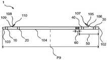
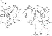
图1表示本发明的实施方式的生物体内留置管的输送系统的侧视图。FIG. 1 is a side view of a delivery system for an indwelling tube in vivo according to an embodiment of the present invention.
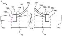
图2表示本发明的实施方式的生物体内留置管的侧视图。FIG. 2 is a side view of the indwelling tube in the living body according to the embodiment of the present invention.
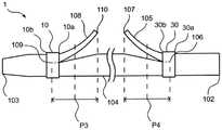
图3表示本发明的实施方式的生物体内留置管的远位翼附近的一个例子的放大侧视图。3 is an enlarged side view showing an example of the vicinity of the distal wing of the indwelling tube in the living body according to the embodiment of the present invention.
图4表示本发明的实施方式的生物体内留置管的远位翼附近的其他的一个例子的放大侧视图。4 is an enlarged side view showing another example of the vicinity of the distal wing of the indwelling tube in the living body according to the embodiment of the present invention.
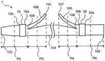
图5表示本发明的实施方式的生物体内留置管的远位翼附近的又一其他的一个例子的放大侧视图。Fig. 5 is an enlarged side view showing yet another example of the vicinity of the distal wing of the indwelling tube in the living body according to the embodiment of the present invention.
图6表示本发明的实施方式的生物体内留置管的远位翼附近的放大侧视图。6 is an enlarged side view of the vicinity of the distal wing of the indwelling tube in the living body according to the embodiment of the present invention.
图7表示本发明的实施方式的生物体内留置管的一个例子的侧视图。Fig. 7 is a side view showing an example of the indwelling tube in the embodiment of the present invention.
图8表示本发明的实施方式的生物体内留置管的其他的一个例子的侧视图。FIG. 8 is a side view showing another example of the indwelling tube in the living body according to the embodiment of the present invention.
图9表示本发明的实施方式的生物体内留置管的其他的一个例子的近位翼为关闭状态的侧视图。9 is a side view showing another example of the indwelling tube in the living body according to the embodiment of the present invention, in which the proximal wings are closed.
图10表示以往的生物体内留置管的侧视图。FIG. 10 is a side view showing a conventional indwelling tube in vivo.
图11表示以往的生物体内留置管的近位翼为关闭状态的近位翼附近的放大侧视图。FIG. 11 is an enlarged side view showing the vicinity of the proximal wing of the conventional indwelling tube in the living body with the proximal wing closed.
图12表示生物体内留置管的翼部的放大侧视图。Fig. 12 is an enlarged side view of the wing portion of the indwelling tube in vivo.
图13表示图12所示的生物体内留置管的翼的XIII-XIII线处的剖视图。Fig. 13 is a cross-sectional view taken along line XIII-XIII of the wing of the indwelling tube shown in Fig. 12 .
图14表示针对测定样本的翼部的拉伸强度的测定方法的说明图。FIG. 14 is an explanatory diagram showing a method for measuring the tensile strength of the wing portion of the measurement sample.
图15表示测定样本的翼部的拉伸强度的测定结果的坐标图。FIG. 15 is a graph showing the measurement results of the tensile strength of the wing portion of the measurement sample.
具体实施方式Detailed ways
以下,基于下述实施方式,更具体地对本发明进行说明,但本发明当然不受到下述实施方式限制,在适合于前述、后述的主旨的范围内适当地施加变更而实施是不言而喻的,它们均包含于本发明的技术范围内。此外,在各附图中,为了方便,也有时省略剖面线、部件附图标记等,但在这样的情况下,参照说明书、其他的附图。另外,附图中各种部件的尺寸使有利于本发明的特征的理解优先,因此有时与实际尺寸不同。Hereinafter, the present invention will be described in more detail based on the following embodiments, but it goes without saying that the present invention is not limited to the following embodiments, and can be implemented with appropriate modifications within the scope suitable for the above-mentioned and later-mentioned gist. Therefore, they are all included in the technical scope of the present invention. In addition, in each drawing, hatching, member reference numerals, etc. may be omitted for convenience, but in such a case, refer to the specification and other drawings. In addition, the dimensions of various components in the drawings are made to facilitate understanding of the features of the present invention, and therefore sometimes differ from actual dimensions.
为了将生物体内留置管运送至病变部,而将生物体内留置管安装于具有设置生物体内留置管的部位的导管等输送系统(运送装置)来使用。In order to transport the indwelling tube to the lesion, the indwelling tube is attached to a delivery system (delivery device) such as a catheter having a site where the indwelling tube is installed.
在本发明中,近位侧是指在生物体内留置管的延伸方向上使用者(做手术的人)的身边侧的方向,远位侧是指与近位侧的相反方向(即处置对象侧的方向)。另外,将从生物体内留置管的近位侧向远位侧的方向称为轴向。径向是指筒状部件的半径方向,径向上内侧是指朝向筒状部件的轴中心侧的方向,径向上外侧是指朝向与内侧相反一侧的放射方向。In the present invention, the proximal side refers to the side of the user (operator) in the extending direction of the indwelling tube in the living body, and the distal side refers to the opposite direction to the proximal side (ie, the treatment target side). direction). In addition, the direction from the proximal side to the distal side of the indwelling tube in vivo is referred to as the axial direction. The radial direction refers to the radial direction of the tubular member, the radially inner side refers to the direction toward the axial center side of the tubular member, and the radially outer side refers to the radial direction toward the opposite side to the inner side.
此外,在以下的实施方式中,有时将生物体内留置管的近位侧的翼(近位翼)和远位侧的翼(远位翼)通称为翼。另外,有时将生物体内留置管的远位侧第1支承体和近位侧第1支承体通称为第1支承体,将远位侧第2支承体和近位侧第2支承体通称为第2支承体,将第1支承体和第2支承体通称为支承体,将远位侧第1支承体和远位侧第2支承体通称为远位侧支承体,将近位侧第1支承体和近位侧第2支承体通称为近位侧支承体。In addition, in the following embodiment, the wings on the proximal side (proximal wings) and the wings on the distal side (distal wings) of the indwelling tube in vivo may be collectively referred to as wings. In addition, the distal-side first support body and the proximal-side first support body of the indwelling tube may be collectively called a first support body, and the distal-side second support body and the proximal-side second support body are collectively called a second support body. 2 Support body, the first support body and the second support body are collectively referred to as the support body, the distal side first support body and the distal side second support body are collectively called the distal side support body, and the proximal side first support body The second support body on the proximal side is collectively referred to as a proximal support body.
(1)输送系统(1) Conveying system
在对本发明的生物体内留置管的制造方法详细说明前,首先参照图1,对将生物体内留置管送达至留置对象部位的输送系统的构成例进行说明。图1示出输送系统的一个例子。输送系统2在内导管3的径向的外侧配置有外导管4和生物体内留置管1。生物体内留置管1和外导管4通过缝合线5而结合。通过将生物体内留置管1和外导管4结合,从而在向病变部运送生物体内留置管1时,能够在生物体内管腔中拉回生物体内留置管1,进行位置的微调节。因此,容易在病变部的适当的位置留置生物体内留置管1。在外导管4的径向的外侧配置有插入辅助管6。能够通过插入辅助管6使翼难以在生物体内留置管1的运送中途折回,并且能够在插入时防止输送系统2的纽结。作为其结果,能够顺利地进行生物体内留置管1的运送。Before describing in detail the manufacturing method of the indwelling tube in vivo of the present invention, a configuration example of the delivery system for delivering the indwelling tube to the indwelling site will be described with reference to FIG. 1 . Figure 1 shows an example of a delivery system. In the delivery system 2 , the
(2)生物体内留置管的整体结构(2) The overall structure of the indwelling tube in vivo
在本发明中,生物体内留置管的特征在于包括:筒状部件,其具有近位侧和远位侧;近位翼,其在筒状部件的近位侧具有近位侧的基部和远位侧的自由端;以及远位翼,其在筒状部件的远位侧具有远位侧的基部和近位侧的自由端,在筒状部件的径向外侧且在比远位翼的基部与自由端之间的中点靠远位侧的位置设置有第1支承体。以下,使用图2~图9对本发明的生物体内留置管进行说明。此外,图2~图9中,纸面左方相当于生物体内留置管的远位侧,纸面右方相当于生物体内留置管的近位侧。In the present invention, the indwelling tube is characterized by comprising: a cylindrical member having a proximal side and a distal side; and a proximal wing having a proximal side base and a distal portion on the proximal side of the cylindrical member and a distal wing having a distal-side base and a proximal-side free end on the distal side of the tubular member, radially outside the tubular member and at a distance from the base of the distal wing A first support body is provided at a position on the distal side of the midpoint between the free ends. Hereinafter, the indwelling tube of the present invention will be described with reference to FIGS. 2 to 9 . 2 to 9 , the left side of the drawing corresponds to the distal side of the indwelling tube in the living body, and the right side of the drawing corresponds to the proximal side of the indwelling tube in the living body.
如图2所示,本发明的实施方式的生物体内留置管1包括:筒状部件104,其具有近位侧和远位侧;近位翼105,其在筒状部件104的近位侧具有近位侧的基部106和远位侧的自由端107;以及远位翼108,其在筒状部件104的远位侧具有远位侧的基部109和近位侧的自由端110。生物体内留置管1具有近位端102和远位端103,并沿轴向延伸。基部106是指近位翼105从筒状部件104立起的基点,自由端107是指从筒状部件104立起的近位翼105的前端。基部109是指远位翼108从筒状部件104立起的基点,自由端110是指从筒状部件104立起的远位翼108的前端。As shown in FIG. 2 , the
如图2~图5所示,筒状部件104具有远位侧第1支承体10和近位侧第1支承体30的至少任一个,上述远位侧第1支承体10在筒状部件104的径向外侧且在比远位翼108的基部109与自由端110之间的中点P3靠远位侧的位置设置,上述近位侧第1支承体30在筒状部件104的径向外侧且在比近位翼105的基部106与自由端107之间的中点P4靠近位侧的位置设置。图2~图5中,示出在筒状部件104设置有远位侧第1支承体10和近位侧第1支承体30双方的例子。即,在比远位翼108的基部109与自由端110之间的中点P3靠远位侧的位置配置有远位侧第1支承体10的近位端10a,在比近位翼105的基部106与自由端107之间的中点P4靠近位侧的位置配置有近位侧第1支承体30的远位端30b。为了防止由于在远位翼108的基部109施加应力而使基部109开裂从而使远位翼108断裂的情况而在筒状部件104的远位翼108附近配置远位侧第1支承体10。与远位侧第1支承体10同样,近位侧第1支承体30也为了防止由于在近位翼105的基部106施加应力而使基部106开裂从而使近位翼105断裂的情况而被配置在筒状部件104的近位翼105附近。此外,针对远位侧第1支承体10以及近位侧第1支承体30的进一步的详情将后述。As shown in FIGS. 2 to 5 , the
(3)筒状部件(3) Cylindrical member
筒状部件104的内径也可以遍及轴向整体为恒定,也可以根据轴向的位置而不同。The inner diameter of the
优选筒状部件104的远位端103的外径小于同远位翼108的自由端110对应的筒状部件104的位置与同近位翼105的自由端107对应的筒状部件104的位置之间的筒状部件104的平均外径。也可以是,筒状部件104的外径在远位端部中朝向远位端103以锥状变小。通过使筒状部件104的远位端103的外径变小,从而容易使生物体内留置管1在生物体内管腔的狭窄部或者堵塞部通过。Preferably, the outer diameter of the
筒状部件104的壁厚能够根据所需要的强度、柔软性而适当地设定,但优选为0.2mm以上0.6mm以下。通过这样设定筒状部件104的壁厚,能够使生物体内留置管1的强度较为充分,并且能够对生物体内留置管1赋予柔软性。The thickness of the
优选筒状部件104的近位端102的壁厚大于同远位翼108的自由端110对应的筒状部件104的位置与同近位翼105的自由端107对应的筒状部件104的位置之间的筒状部件104的平均壁厚。通过使筒状部件104的近位端102的壁厚成为这样,能够提高生物体内留置管1的推进能力。优选近位端102的端面为平坦。由此,生物体内留置管1的近位端102端面的强度为恒定,能够提高生物体内留置管1的推进能力。另外,也可以是,近位端102的端面为了防止损伤体腔内而外周被倒角。Preferably, the wall thickness of the
作为构成筒状部件104、近位翼105以及远位翼108的材料,可举出:聚酰胺系树脂、聚酯系树脂、聚氨酯系树脂、聚烯烃系树脂、氟树脂、氯乙烯系树脂、有机硅系树脂、天然橡胶等。这些也可以仅使用1种,也可以2种以上一起并用。其中,优选使用聚酰胺系树脂、聚酯系树脂、聚氨酯系树脂、聚烯烃系树脂、氟树脂。此外,构成筒状部件104、近位翼105以及远位翼108的材料也可以相同,也可以不同。若构成筒状部件104、近位翼105以及远位翼108的材料相同,则生物体内留置管1的整体的强度、柔软性均匀。另外,例如,通过使构成近位翼105和远位翼108的材料成为比构成筒状部件104的材料硬度更高的材料,从而能够成为虽然近位翼105以及远位翼108的针对生物体内管腔的保持力较高,但还可保持筒状部件104的柔软性的生物体内留置管1。Examples of materials constituting the
(4)第1区域以及第2区域(4) The first area and the second area
如图2所示,优选筒状部件104从近位侧起依次具有第1区域50和第2区域60,在比近位翼105的基部106靠远位侧的位置处,第1区域50与第2区域60的颜色互不相同。第1区域50与第2区域60的颜色互不相同是指在第1区域50的颜色和第2区域60的颜色中,根据JISZ8721规定的色相、亮度以及色彩饱和度的至少一个不同。筒状部件104具有第1区域50和第2区域60,第1区域50与第2区域60的颜色互不相同,由此在将生物体内留置管1向生物体内管腔的所希望的位置运送时,容易通过内窥镜确认生物体内留置管1的近位翼105的位置。第2区域60的颜色是与第1区域50不同的颜色,只要是内窥镜下容易视认的颜色,则容易确认第1区域50与第2区域60的边界,容易确认生物体内留置管1的近位翼105。例如,也可以是,第1区域50的颜色是黑色等亮度低的颜色,第2区域60的颜色是黄色等亮度高的颜色。另外,也可以是,第1区域50的颜色是亮度高的颜色,第2区域60的颜色是亮度低的颜色。As shown in FIG. 2 , the
也可以是,除了第1区域50以及第2区域60之外,筒状部件104还在比近位翼105的基部106靠近位侧的位置具有与第1区域50和第2区域60的至少任一个颜色不同的区域。若筒状部件104在比近位翼105的基部106靠近位侧的位置具有颜色不同的区域,则容易辨别生物体内留置管1的近位端102和远位端103。另外,若在比近位翼105的基部106靠近位侧的位置不具有颜色不同的区域,则第1区域50醒目,在内窥镜下第1区域50的可视性提高。In addition to the
使第1区域50与第2区域60的颜色互不相同的方法例如可举出:在筒状部件104中对成为第1区域50和第2区域60的部分的至少一方进行着色的方法、在成为第1区域50和第2区域60的部分的至少一方配置与筒状部件104颜色不同的膜、筒型构件的方法等。作为对筒状部件104的成为第1区域50和第2区域60的部分的至少一方进行着色的方法,可举出:涂覆涂料的通过染料进行染色等方法。其中,优选在筒状部件104的成为第1区域50的部分涂覆与筒状部件104不同颜色的涂料来进行着色。通过这样使第1区域50与第2区域60的颜色互不相同,从而能够提高在内窥镜中生物体内留置管1的近位翼105的位置的可视性。另外,也可以是,筒状部件104在比第2区域60靠远位侧的位置具有与第2区域60不同颜色的区域。此外,也可以是,使后述的近位侧第2支承体40的颜色成为与第1区域50的颜色不同的颜色,将近位侧第2支承体40作为第2区域60。As a method of making the colors of the
能够将第1区域50以及第2区域60的轴向的长度以容易视认的方式适当地设定。优选第1区域50的近位端50a处于筒状部件104的比近位翼105的基部106靠近位侧的位置,第1区域50的远位端50b处于筒状部件104的比近位翼105的基部106靠远位侧的位置。此外,也可以是,第1区域50的近位端50a处于筒状部件104的比近位翼105的基部106靠远位侧的位置。另外,也可以是,第1区域50的近位端50a与筒状部件104的近位端102一致。The axial lengths of the
如图7~图9所示,优选第2区域60的近位端60a被配置在比同近位翼105的自由端107对应的筒状部件104的位置P2靠远位侧的位置。同近位翼105的自由端107对应的筒状部件104的位置P2是指在使近位翼105沿着筒状部件104而近位翼105为关闭的状态时近位翼105的自由端107与筒状部件104相接的位置。As shown in FIGS. 7 to 9 , it is preferable that the
(5)近位翼以及远位翼(5) Near wing and far wing
近位翼105设置于筒状部件104的近位端部,远位翼108设置于筒状部件104的远位端部。也可以是,近位翼105以及远位翼108例如通过在筒状部件104的端部的表面形成切口来形成。另外,也可以通过将构成近位翼105或者远位翼108的与筒状部件104不同的构件亦即翼构件设置于筒状部件104的近位端部、远位端部来形成。在这种情况下,能够采用将翼构件接合于筒状部件104等的方法。近位翼105与远位翼108可以通过相同的方法形成,也可以通过不同的方法形成。The
在将近位翼构件或者远位翼构件接合于筒状部件104的外表面而形成翼的情况下,翼构件与构成筒状部件104的材料可以相同,也可以不同。作为筒状部件104与翼构件接合的接合方法,可举出热熔融、超声波熔融、基于粘结剂的粘结等,但优选为基于热熔融的接合。通过利用热熔融将筒状部件104与翼构件接合,能够提高筒状部件104与翼构件的接合强度。When the proximal wing member or the distal wing member is joined to the outer surface of the
当在十二指肠的乳头附近存在癌等病变部的情况下,生物体内留置管1的近位翼105附近可能与病变部接触。在这种情况下,若在筒状部件104的近位翼105附近,存在为了制成近位翼105而通过在筒状部件104形成切口而形成的孔,则担心使癌细胞等从该孔侵入到生物体内留置管1的内腔,使生物体内留置管1的内腔堵塞或者变狭窄。因此,优选在癌等病变部可能向近位翼105附近接触的情况下等,通过以不形成能够使癌细胞等侵入近位翼105附近的程度的大小的孔的方式将近位翼构件设置于筒状部件104,来形成近位翼105。When a lesion such as cancer exists near the papilla of the duodenum, the vicinity of the
在从生物体内回收生物体内留置管1时,为了防止远位翼108断裂,优选提高远位翼108的强度。为了提高远位翼108的强度,优选通过在筒状部件104的远位端部形成切口而将远位翼108和筒状部件104一体形成。When recovering the
近位翼105在从近位侧朝向远位侧的轴向上并且朝向径向的外侧延伸。远位翼108在从远位侧朝向近位侧的轴向上并且朝向径向的外侧延伸。也可以分别设置一个或者多个近位翼105以及远位翼108,例如,也可以允许2个以上、3个以上、或者5个以下。优选在设置有多个近位翼105或者远位翼108的情况下,各翼在筒状部件104的周向上以等间隔配置。通过将多个近位翼105这样配置,能够提高防止生物体内留置管1的近位端102进入生物体内管腔的效果。通过将多个远位翼108这样配置,能够提高防止生物体内留置管1从生物体内管腔脱落的效果。另外,在设置有多个近位翼105或者远位翼108的情况下,从后述的翼的基部至自由端为止的长度、翼的宽度、厚度也可以全部相同,也可以不同。例如,若各翼的长度、宽度、厚度相同,则制造变容易。另外,各翼的长度、宽度、厚度不同,由此能够改变各个翼的强度。作为具体例,可举出提高容易被施加应力而存在断裂担忧的位置的翼的强度、降低被要求柔软性的位置的翼的强度等。The
从近位翼105的基部106至自由端107为止的长度、以及从远位翼108的基部109至自由端110为止的长度未特别限定,但优选为4mm以上且15mm以下。通过这样设定从翼的基部至自由端为止的长度,由此能够使翼具有足够的弹性,能够防止生物体内留置管1进入所希望的位置以外的位置。The length from the base 106 to the
近位翼105的壁厚未特别限定,但通过使近位翼105的壁厚比筒状部件104的近位端的壁厚薄,由此能够使与近位翼105接触的生物体内管腔难以损伤。通过使近位翼105的壁厚大于筒状部件104的近位端的壁厚,能够提高近位翼105的强度。另外,近位翼105的壁厚从基部106至自由端107也可以恒定,也可以不同。例如,也可以是,从近位翼105的基部106朝向自由端107具有壁厚减少的部分。The wall thickness of the
远位翼108的壁厚未特别限定,但优选比筒状部件104的近位端102的壁厚薄。通过使远位翼108的壁厚小于筒状部件104的近位端102的壁厚,能够防止远位翼108刺穿或损伤生物体内管腔的管壁。另外,优选远位翼108的壁厚大于同远位翼108的自由端110对应的筒状部件104的位置与同近位翼105的自由端107对应的筒状部件104的位置之间的筒状部件104的平均壁厚。通过使远位翼108的壁厚成为这样,从而能够提高远位翼108的针对生物体内管腔的保持力。The wall thickness of the
近位翼105与远位翼108的壁厚、长度可以相同,也可以不同。例如,通过使近位翼105的长度大于远位翼108的长度,从而能够提高防止近位翼105向径向外侧大幅打开而使生物体内留置管1的近位端102向生物体内管腔进入的效果。通过使远位翼108的长度大于近位翼105的长度,从而能够增大远位翼108的打开大小,能够提高针对生物体内管腔的保持力。若近位翼105的壁厚小于远位翼108的壁厚,则近位翼105难以与内窥镜的管路内壁干扰而具有输送性能提高的效果。若近位翼105的壁厚大于远位翼108的壁厚,则近位翼105的强度提高,从而能够提高防止生物体内留置管1的近位端102进入生物体内管腔的效果。优选近位翼105和远位翼108的壁厚为0.2mm以上且0.6mm以下。此外,翼的壁厚从翼的基部至自由端也可以恒定,也可以不同。The wall thickness and length of the
构成近位翼105、远位翼108的材料未特别限定,但能够使用作为构成筒状部件104的树脂而举出的材料。此外,构成翼的材料与构成筒状部件104的材料可以相同,也可以不同。若构成翼的材料与构成筒状部件104的材料相同,则筒状部件104与翼的接合性变好,容易在筒状部件104设置翼。若构成翼的材料与构成筒状部件104的材料不同,则例如使构成筒状部件104的材料较为柔软,从而能够成为筒状部件104的柔软性较高但翼的强度较高的生物体内留置管1。The material constituting the
优选构成近位翼105的材料的硬度(A型硬度计硬度)大于构成同远位翼108的自由端110对应的筒状部件104的位置与同近位翼105的自由端107对应的筒状部件104的位置之间的筒状部件104的材料的平均硬度(A型硬度计硬度)。A型硬度计硬度能够通过以JISK7215为基准的方法来测定。通过提高构成近位翼105的材料的硬度,从而近位翼105的刚性增大,进而能够提高将生物体内留置管1固定于生物体内管腔的功能。Preferably, the hardness (type A durometer hardness) of the material constituting the
(6)远位侧第1支承体以及近位侧第1支承体的优选配置(6) Preferred arrangement of the distal-side first support body and the proximal-side first support body
如图3所示,优选远位侧第1支承体10设置于比远位翼108的基部109靠近位侧的位置,近位侧第1支承体30设置于比近位翼105的基部106靠远位侧的位置。即,优选在比远位翼108的基部109与自由端110之间的中点P3靠远位侧的位置配置有远位侧第1支承体10的近位端10a,在比远位翼108的基部109靠近位侧的位置配置有远位侧第1支承体10的远位端10b。另外,优选在比近位翼105的基部106与自由端107之间的中点P4靠近位侧的位置配置有近位侧第1支承体30的远位端30b,在比近位翼105的基部106靠远位侧的位置配置有近位侧第1支承体的近位端30a。通过这样配置远位侧第1支承体10,能够在对远位翼108施加了应力时通过远位侧第1支承体10承受该应力。作为其结果,能够防止应力施加于远位翼108的基部109而使基部109开裂进而该基部109的裂缝到达筒状部件104的远位端103而使远位翼108断裂的情况。另外,通过这样配置近位侧第1支承体30,与远位侧第1支承体10同样,能够在对近位翼105施加了应力时通过近位侧第1支承体30承受该应力,从而能够防止近位翼105断裂。As shown in FIG. 3 , it is preferable that the distal-side
如图4所示,也优选远位侧第1支承体10设置在远位翼108的基部106上,近位侧第1支承体30设置在近位翼105的基部106上。即,优选在比远位翼108的基部109与自由端110之间的中点P3靠远位侧且比基部109靠近位侧的位置配置有远位侧第1支承体10的近位端10a,在比基部109靠远位侧的位置配置有远位侧第1支承体10的远位端10b。另外,优选在比近位翼105的基部106与自由端107之间的中点P4靠近位侧且比基部106靠远位侧的位置配置有近位侧第1支承体30的远位端30b,在比基部106靠近位侧的位置配置有近位侧第1支承体的近位端30a。通过这样配置远位侧第1支承体10,能够通过远位侧第1支承体10承受施加于远位翼108的应力。因此,能够防止在远位翼108的基部109施加应力使基部109开裂进而使远位翼108断裂的情况。另外,通过这样配置近位侧第1支承体30,与远位侧第1支承体10同样,能够通过近位侧第1支承体30承受施加于近位翼105的应力,能够防止近位翼105断裂。As shown in FIG. 4 , it is also preferable that the distal-side
如图5所示,优选远位侧第1支承体10设置于比远位翼108的基部109与筒状部件104的远位端103之间的中点P5靠近位侧的位置,近位侧第1支承体30设置于比近位翼105的基部106与筒状部件104的近位端102之间的中点P6靠远位侧的位置。即,优选在比远位翼108的基部109与自由端110之间的中点P3靠远位侧且比基部109靠远位侧的位置配置有远位侧第1支承体10的近位端10a,在比基部109与筒状部件104的远位端103之间的中点P5靠近位侧的位置配置有远位侧第1支承体10的远位端10b。另外,优选在比近位翼105的基部106与自由端107之间的中点P4靠近位侧且比基部106靠近位侧的位置配置有近位侧第1支承体30的远位端30b,在比基部106与筒状部件104的近位端102之间的中点P6靠远位侧的位置配置有近位侧第1支承体30的近位端30a。通过这样配置远位侧第1支承体10,即便在对远位翼108的基部109施加应力而导致基部109局部开裂的情况下,也能够防止越过远位侧第1支承体10而使基部109开裂至筒状部件104的远位端103的情况,从而能够防止远位翼108的断裂。另外,通过这样配置近位侧第1支承体30,与远位侧第1支承体10同样,能够在对近位翼105施加了应力时通过近位侧第1支承体30承受该应力,能够防止近位翼105断裂。As shown in FIG. 5 , the distal-side
(7)远位侧第2支承体以及近位侧第2支承体(7) Distal side second support body and proximal side second support body
为了提高生物体内留置管1整体的强度,也可以设置有远位侧第2支承体20与近位侧第2支承体40的至少任一个。详细而言,也可以设置有在比远位翼108的自由端110靠近位侧且比筒状部件104的中点P9靠远位侧的位置设置的远位侧第2支承体20、和在比近位翼105的自由端107靠远位侧且比筒状部件104的中点P9靠近位侧的位置设置的近位侧第2支承体40中的至少任一个。例如,担心由于远位翼108附近的筒状部件104的强度低的部分过度折弯而难以将生物体内留置管1运送至所希望的留置部分。这样,通过在欲提高生物体内留置管1的强度的部分设置远位侧第2支承体20或者近位侧第2支承体40,从而生物体内留置管1整体的强度提高,进而能够提高推进能力。In order to improve the overall strength of the
(8)远位侧第1支承体、远位侧第2支承体、近位侧第1支承体以及近位侧第2支承体的结构(8) Configurations of the distal-side first support body, the distal-side second support body, the proximal-side first support body, and the proximal-side second support body
在生物体内留置管1至少设置有远位侧第1支承体和近位侧第1支承体的任一个。也可以是,在生物体内留置管1,除了设置有远位侧第1支承体、近位侧第1支承体之外,还设置有远位侧第2支承体和近位侧第2支承体的至少任一个。The
各支承体的形状虽未特别限定,但优选为筒状,可举出圆筒状、多角筒状、在筒形成有狭缝的剖面为C字型的形状、卷绕有线材的线圈形状等。其中,优选远位侧第1支承体10、远位侧第2支承体20、近位侧第1支承体30以及近位侧第2支承体40的至少任一个的形状为筒状。远位侧第1支承体10的形状为筒状,由此当对远位翼108施加了外力时,能够通过远位侧第1支承体10整体承受该外力,从而能够防止远位翼108断裂的情况。近位侧第1支承体30的形状为筒状,由此当对近位翼105施加了外力时,能够通过近位侧第1支承体30整体承受该外力,能够防止近位翼105断裂。另外,在远位侧第2支承体20和近位侧第2支承体40的至少任一个的形状为筒状的情况下,起到提高设置有生物体内留置管1的远位侧第2支承体20和近位侧第2支承体40的至少任一个的位置的强度的效果。在生物体内留置管设置的支承体的所有形状可以相同,也可以不同。Although the shape of each support body is not particularly limited, it is preferably a cylindrical shape, and examples thereof include a cylindrical shape, a polygonal cylindrical shape, a C-shaped cross-section in which a slit is formed in the cylinder, and a coil shape in which a wire is wound. . Among them, it is preferable that at least any one of the distal-side
从第1支承体的近位端至远位端为止的长度亦即第1支承体的轴向的长度未特别限定,但若支承体的长度变长则防止翼的断裂的效果提高,若变短,则能够保持生物体内留置管1的柔软性。第1支承体的轴向的长度能够根据需要的效果适当地选择。与第1支承体的轴向的长度同样,第2支承体的轴向的长度也能够根据所需要的效果而设定。各个支承体的长度可以相同,也可以不同。在图3中,远位侧第1支承体10的轴向的长度是从远位侧第1支承体的近位端10a至远位端10b为止的长度。同样,近位侧第1支承体30的轴向的长度是从近位侧第1支承体30的近位端30a至远位端30b为止的长度。The length from the proximal end to the distal end of the first support body, that is, the length in the axial direction of the first support body is not particularly limited. If it is short, the flexibility of the
支承体的壁厚未特别限定,但若支承体的壁厚变厚则防止翼的断裂的效果提高。另外,若支承体的壁厚变薄,则生物体内留置管1的柔软性提高,支承体与筒状部件的阶梯差变小。作为其结果,容易将生物体内留置管1运送至病变部。The thickness of the support body is not particularly limited, but when the thickness of the support body is increased, the effect of preventing breakage of the wings increases. In addition, when the thickness of the support body is reduced, the flexibility of the
优选支承体的至少任一个的内径小于筒状部件104的外径。由此,成为支承体稳固地固定于筒状部件104的状态,支承体难以从生物体内留置管1脱离。对于使支承体的内径小于筒状部件104的外径而言,例如通过以下方法来实现即可,即,由金属构成支承体,在支承体的轴向形成切口,并在筒状部件104的径向外侧配置支承体后,将支承体扣合并使支承体的形成了切口的部分叠合,从而使支承体的内径变小,或者由热收缩性的树脂构成支承体,形成为支承体的内径大于或等于筒状部件104的外径的筒形状,对支承体加热而使支承体的内径比筒状部件104的外径收缩即可。The inner diameter of at least one of the supports is preferably smaller than the outer diameter of the
构成支承体的材料未特别限定,但例如可举出,不锈钢、钛、钴铬合金、铂铱合金等金属、聚酰胺系树脂、聚酯系树脂、聚氨酯系树脂、聚烯烃系树脂、氟树脂、氯乙烯系树脂、有机硅系树脂、天然橡胶等树脂。其中,优选构成支承体的至少任一个的材料强度比构成筒状部件104的材料高。The material constituting the support is not particularly limited, and examples thereof include metals such as stainless steel, titanium, cobalt-chromium alloy, and platinum-iridium alloy, polyamide-based resin, polyester-based resin, polyurethane-based resin, polyolefin-based resin, and fluororesin. , vinyl chloride resin, silicone resin, natural rubber and other resins. Among them, it is preferable that the strength of at least one of the materials constituting the support body is higher than that of the material constituting the
作为强度比构成筒状部件104的材料高的材料,例如可举出,金属、A型硬度计硬度比构成筒状部件104的材料高的树脂。即,在构成支承体的至少任一个的材料为树脂的情况下,优选该材料的硬度(A型硬度计硬度)比构成筒状部件104的材料的硬度(A型硬度计硬度)高。A型硬度计硬度能够通过以JIS K7215为基准的方法测定。构成第1支承体的材料强度比构成筒状部件104的材料高,由此能够防止翼的基部开裂至筒状部件104的端部,从而能够防止翼的断裂。As a material having higher strength than the material constituting the
为了能够通过X射线透视等检测生物体内留置管1的位置,构成支承体的至少任一个的材料也可以包含X射线不透过材料。为了提高内窥镜下的生物体内留置管1的可视性,优选使构成支承体的至少任一个的材料成为与筒状部件104不同的颜色、或成为与筒状部件104不同的材料。例如,也可以是,通过使近位侧第2支承体40的颜色成为与筒状部件104的第1区域50的颜色不同的颜色,从而将近位侧第2支承体40作为第2区域60。In order to be able to detect the position of the
也可以是,一个或多个支承体设置于筒状部件104,例如也允许2个以上、或者4个以下。例如,在多个远位侧第1支承体10设置于筒状部件104的情况下,能够更加提高远位翼108的断裂防止效果。One or more supports may be provided in the
如图6所示,优选远位侧第1支承体10的近位端10a与远位侧第2支承体20的远位端20b之间的中点P7处于比远位翼108的自由端110靠远位侧的位置,近位侧第1支承体30的远位端30b与近位侧第2支承体40的近位端40a之间的中点P8处于比近位翼105的自由端107靠近位侧的位置。例如,在通过在筒状部件104的远位侧形成切口来形成远位翼108的情况下,生物体内留置管1的远位翼108附近的强度降低,从而在将生物体内留置管1向生物体内管腔的所希望的留置部分运送时,担心生物体内留置管1的远位翼108附近折弯,使生物体内留置管1的推进能力降低。针对近位翼105也同样,当在筒状部件104的近位侧形成切口而形成近位翼的情况下,担心生物体内留置管1的近位翼105附近折弯,使生物体内留置管1的推进能力降低。因此,通过这样配置远位翼108、远位侧第1支承体10、远位侧第2支承体20,并且这样配置近位翼105、近位侧第1支承体30、近位侧第2支承体40,从而通过远位侧第1支承体10和远位侧第2支承体20提高生物体内留置管1的远位翼108附近的强度,通过近位侧第1支承体30和近位侧第2支承体40提高生物体内留置管1的近位翼105附近的强度,进而能够防止远位翼108、近位翼105的折弯。As shown in FIG. 6 , it is preferable that the midpoint P7 between the
(9)具有大径部的结构(9) Structure with large diameter portion
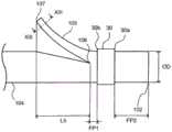
如图7所示,优选生物体内留置管1在比近位翼105的基部106靠近位侧的位置和比远位翼108的基部109靠远位侧的位置的至少任一个位置具有大径部111,上述大径部111的最大外径大于同远位翼108的自由端110对应的筒状部件104的位置P1或者远位侧第2支承体20的近位端20a、与同近位翼105的自由端107对应的筒状部件104的位置P2或者第1区域50的远位端50b之间的筒状部件104的平均外径。同远位翼108的自由端110对应的筒状部件104的位置P1是指在使远位翼108沿着筒状部件104而远位翼108为关闭的状态时远位翼108的自由端110与筒状部件104接触的位置。同近位翼105的自由端107对应的筒状部件104的位置P2是指在使近位翼105沿着筒状部件104而近位翼105为关闭的状态时近位翼105的自由端107与筒状部件104接触的位置。能够在比近位翼105的基部106靠近位侧的位置具有大径部111,从而能够提高近位翼105的强度,防止近位翼105的断裂。同样,通过在比远位翼108的基部109靠远位侧的位置具有大径部111,从而能够提高远位翼108的强度。As shown in FIG. 7 , the
对于在比近位翼105的基部106靠近位侧的位置形成大径部111而言,例如将构成近位翼105的翼构件叠合在筒状部件104的径向外侧地配置并在筒状部件104的外表面接合翼构件即可。由于在翼构件与筒状部件104相互接合的部分处外径变大,所以在生物体内留置管1的比近位翼105的基部106靠近位侧的位置形成有大径部111。并且,通过这样制造生物体内留置管1,从而在近位翼105的基部106附近没有形成孔,进而能够防止癌细胞等病变部经由孔侵入生物体内留置管1的内腔。For forming the large-
对于在比远位翼108的基部109靠远位侧的位置形成大径部111而言,与在比近位翼105的基部106靠近位侧的位置形成大径部111的方法同样,可举出:将构成远位翼108的翼构件叠合在筒状部件104的径向地配置,并在筒状部件104的外表面接合翼构件的方法等。通过这样形成远位翼108,从而在翼构件与筒状部件104相互接合的部分处外径变大,因此在生物体内留置管1的比远位翼108的基部109靠远位侧的位置形成有大径部111。For forming the large-
(10)具有小径部的结构(10) Structure with small diameter portion
优选小径部在从翼的基部至关闭状态的翼的自由端之间设置。优选小径部的轴向的长度小于从翼的基部至关闭状态的翼的自由端为止的长度。如图8所示,优选筒状部件104具有小径部114,上述小径部114的最小外径小于同远位翼108的自由端110对应的筒状部件104的位置P1或者远位侧第2支承体20的近位端20a、与同近位翼105的自由端107对应的筒状部件104的位置P2或者第1区域50的远位端50b之间的筒状部件104的平均外径,在近位翼105的基部106与比近位翼105为关闭状态的近位翼105的自由端107靠近位侧的位置之间、和远位翼108的基部109与比远位翼108为关闭状态的远位翼108的自由端110靠远位侧的位置之间的至少任一个设置有小径部114。在这种情况下,如图9所示,优选或者近位翼105为关闭状态的近位翼105的自由端107处于比小径部114的远位端116靠远位侧的位置,或者远位翼108为关闭状态的远位翼108的自由端110处于比小径部114的近位端115靠近位侧的位置,或者至少处于任一个。翼的关闭状态是指使翼沿着筒状部件104而翼关闭的状态。此外,也可以是,小径部114通过具有后述的孔,从而小径部114的最小外径小于同远位翼108的自由端110对应的筒状部件104的位置P1或者远位侧第2支承体20的近位端20a、与同近位翼105的自由端107对应的筒状部件104的位置P2或者第1区域50的远位端50b之间的筒状部件104的平均外径。另外,也可以是,对小径部114而言,通过不具有孔而同远位翼108的自由端110对应的筒状部件104的位置P1或者远位侧第2支承体20的近位端20a、与同近位翼105的自由端107对应的筒状部件104的位置P2或者第1区域50的远位端50b之间的筒状部件104的外径整体变小,从而小径部114的最小外径比筒状部件104的平均外径小。Preferably, the small diameter portion is provided from the base of the wing to the free end of the wing in the closed state. The axial length of the small diameter portion is preferably smaller than the length from the base portion of the blade to the free end of the blade in the closed state. As shown in FIG. 8 , the
通过在近位翼105的基部106与比近位翼105为关闭状态的近位翼105的自由端107靠近位侧的位置之间设置有小径部114,从而能够使当近位翼105为关闭状态时筒状部件104和近位翼105重叠的位置的筒状部件104的外径变小。通过在远位翼108的基部109与比远位翼108为关闭状态的远位翼108的自由端110靠远位侧的位置之间设置有小径部114,从而能够使在关闭了远位翼108的状态时筒状部件104与远位翼108重叠的位置的筒状部件104的外径变小。此外,通过使筒状部件104与翼重叠的位置的筒状部件104的外径变小,从而当使生物体内留置管1通过内窥镜的管路等时,管路的内壁与生物体内留置管1难以干扰,从而在管路的通过变顺畅。By providing the
对于在近位翼105的基部106与比近位翼105为关闭状态的近位翼105的自由端107靠近位侧的位置之间、或者在远位翼108的基部109与比远位翼108为关闭状态的远位翼108的自由端110靠远位侧的位置之间形成小径部114而言,例如可举出:削掉筒状部件104的近位端部而在筒状部件104形成开口部,并在该开口部配置构成翼的翼构件的方法;由构成翼的含有翼筒型部件、在比含有翼筒型构件靠远位侧的位置配置的远位侧筒型部件、在含有翼筒型部件和远位侧筒型部件的内腔配置的内腔筒型部件这3种部件构成筒状部件104的近位端部,并将远位侧筒型部件的近位端配置于比含有翼筒型部件的翼的基部靠远位侧或者靠近位侧的位置的方法等。通过这样制造生物体内留置管1,从而在生物体内留置管1的比翼的基部靠远位侧或靠近位侧的位置形成有小径部114,能够使在翼为沿着筒状部件104关闭的状态时筒状部件104与翼重叠的位置的外径变小。For between the base 106 of the
如图10以及图11所示,以往的生物体内留置管201在筒状部件204形成切口而形成近位翼205。因此,在使近位翼205沿着筒状部件204而近位翼205关闭的状态下,近位翼205的自由端207位于比小径部214的远位端216靠近位侧的位置。针对远位翼208也同样在筒状部件204形成切口而形成远位翼208。因此,在使远位翼208沿着筒状部件204而远位翼208关闭的状态下,远位翼208的自由端210位于比小径部214的近位端215靠远位侧的位置。As shown in FIGS. 10 and 11 , in the conventional
如图8以及图9所示,对于本发明的生物体内留置管1而言,当在近位翼105的基部106与比近位翼105为关闭状态的近位翼105的自由端107靠近位侧的位置之间设置有小径部114的情况下,在近位翼105关闭的状态下,近位翼105的自由端107位于比小径部114的远位端116靠远位侧的位置。另外,优选小径部114的轴向的长度比近位翼105的轴向的长度短。As shown in FIGS. 8 and 9 , for the
当在远位翼108的基部109与比远位翼108为关闭状态的远位翼108的自由端110靠远位侧的位置之间设置有小径部114的情况下,在远位翼108关闭的状态下,远位翼108的自由端110位于比小径部114的近位端115靠近位侧的位置。另外,优选小径部114的轴向的长度比远位翼108的轴向的长度短。When the
优选针对小径部114的位置,在翼的基部与翼为关闭状态的翼的自由端的位置之间设置有小径部114。也可以是,小径部偏向翼的基部侧或者自由端侧而设置。特别优选设置于翼的基部侧。As for the position of the small-
也可以是,筒状部件104在小径部114中具有孔。也可以是,孔是供筒状部件104的内腔与筒状部件104的外部连通的贯通孔。另外,也可以是,孔为筒状部件104上的凹陷,且不供筒状部件104的内腔与筒状部件104的外部连通。The
与孔的深度方向垂直的面的孔的截面积未特别限定,但优选比筒状部件104的内腔的最大截面积小。若孔的大小成为这样,则即便在癌细胞等病变部与孔接触的情况下,病变部也难以从孔向生物体内留置管1的内腔侵入。The cross-sectional area of the hole in the plane perpendicular to the depth direction of the hole is not particularly limited, but is preferably smaller than the maximum cross-sectional area of the lumen of the
孔的形状未特别限定,例如可举出圆形、椭圆形、矩形、多边形等。另外,筒状部件104的轴向上的孔的长度也可以遍及小径部114的全域,也可以比从小径部114的远位端116至近位端115为止的长度短。The shape of the hole is not particularly limited, and examples thereof include a circle, an ellipse, a rectangle, and a polygon. The length of the hole in the axial direction of the
孔的位置也可以从翼的基部遍及翼的关闭状态的自由端的位置,也可以更小。优选与筒状部件104的轴向正交的方向的孔的长度比与近位翼105的轴向正交的方向的长度短。通过使孔的形状成为这样,从而能够降低癌细胞等病变部经由孔向生物体内留置管1的内腔侵入的可能性。The location of the holes can also be from the base of the wing throughout the location of the free end of the wing in the closed state, or it can be smaller. Preferably, the length of the hole in the direction orthogonal to the axial direction of the
设置有支承体的生物体内留置管1的制造方法的例子如以下所示。在为本制造方法的情况下,筒状部件104成为包括内管和外管的多层构造,并在筒状部件104的层间配置有支承体。根据本制造方法,能够在所希望的位置配置翼或者支承体。An example of the manufacturing method of the
首先,使支承体覆盖于内管。支承体可以为环状的形状,可以为板状,也可以为C字状。在支承体为环状的情况下,使支承体穿过内管,在内管上配置支承体。另外,在支承体为板状的情况下,使支承体以沿着内管的外周的形状变圆并固定端部,从而在内管上配置支承体。也可以是,在使环状、C字状的支承体覆盖了内管后,使支承体缩径并以内管状安装。板状、C字状的支承体的端部的固定能够使用熔融、粘结等任意的方法。First, the inner tube is covered with a support body. The support body may have an annular shape, a plate shape, or a C-shape. When the support body is annular, the support body is passed through the inner tube, and the support body is arranged on the inner tube. Moreover, when a support body is a plate shape, a support body is arrange|positioned on an inner tube by rounding a support body in the shape along the outer periphery of an inner tube, and fixing an end part. After covering the inner tube with an annular and C-shaped support body, the diameter of the support body may be reduced and the inner tube may be attached. An arbitrary method such as melting and bonding can be used for fixing the ends of the plate-shaped and C-shaped support bodies.
接下来,使外管覆盖于内管的支承体上的至少一部分。外管为至少覆盖支承体的长度即可,也可以为与内管相同的长度、或比内管长。内管与外管的材料也可以相同,也可以不同。优选内管和外管的材料选择在固定内管和外管的工序中容易固定的材料。外管的内径为了能够将内管配置于其内腔而优选为比内管的外径大。由此,使外管覆盖于内管的作业变容易。筒状部件104也可以在支承体的上侧或者下侧为多层。通过控制各层的厚度、材质,能够控制生物体内留置管1的尺寸、硬度。Next, at least a part of the support body of the inner tube is covered with the outer tube. The outer tube may have a length covering at least the support body, and may be the same length as the inner tube or longer than the inner tube. The materials of the inner tube and the outer tube may be the same or different. The material of the inner tube and the outer tube is preferably selected from a material that can be easily fixed in the process of fixing the inner tube and the outer tube. The inner diameter of the outer tube is preferably larger than the outer diameter of the inner tube so that the inner tube can be arranged in the lumen. Thereby, the work of covering the inner tube with the outer tube is facilitated. The
使重叠的内管和外管固定。在内管、外管为热塑性的材料的情况下,在内管以及外管上覆盖热收缩管,进行加热并通过热熔融来固定内管和外管。也能够在内管与外管之间注入粘结剂来固定。Secure the overlapping inner and outer tubes. When the inner tube and the outer tube are made of thermoplastic materials, the inner tube and the outer tube are covered with a heat-shrinkable tube, heated, and the inner tube and the outer tube are fixed by heat fusion. It is also possible to inject adhesive between the inner tube and the outer tube for fixing.
使用切断单元在由固定好的内管和外管构成的筒状部件104的规定位置形成切口,从而形成翼部。优选切断单元是能够将筒状部件104较薄地切片的刃具。翼部的形成例如能够通过利用刀等刃具来切削筒状部件104而进行,通过利用剪刀等在筒状部件104形成切口等而进行。翼部的位置能够根据与支承体之间的关系而形成于筒状部件104的规定位置。The wing portion is formed by forming a cutout at a predetermined position of the
以上的制造方法在远位侧支承体中、在近位侧支承体中均能够应用。在制造将支承体设置于比翼的基部与筒状部件104的端部之间的中点靠基部侧的位置的生物体内留置管1的情况下,通过使内管的壁厚大于外管的壁厚,使翼的厚度比外管更厚,能够提高翼的耐撕裂性,从而提高翼的强度。The above manufacturing method can be applied to both the distal side support and the proximal side support. When manufacturing the
如以上那样,本发明的生物体内留置管的特征在于,包括:筒状部件,其具有近位侧和远位侧;近位翼,其在筒状部件的近位侧具有近位侧的基部和远位侧的自由端;以及远位翼,其在筒状部件的远位侧具有远位侧的基部和近位侧的自由端,筒状部件具有远位侧第1支承体和近位侧第1支承体的至少任一个,上述远位侧第1支承体被设置在筒状部件的径向外侧且比远位翼的基部与自由端之间的中点靠远位侧的位置,上述近位侧第1支承体被设置在筒状部件的径向外侧且比近位翼的基部与自由端之间的中点靠近位侧的位置。通过成为这样的结构,能够维持生物体内留置管本身的柔软性,并且提高远位翼与近位翼的至少任一个的强度。As described above, the indwelling tube of the present invention is characterized by comprising: a tubular member having a proximal side and a distal side; and a proximal wing having a proximal-side base on the proximal side of the tubular member and a free end on the distal side; and a distal wing having a base on the distal side and a free end on the proximal side on the distal side of the tubular member, the tubular member having a first support body on the distal side and a proximal side at least one of the side first supports, the distal side first supports are provided on the radially outer side of the cylindrical member and at a position on the distal side from the midpoint between the base and the free end of the distal wing, The said proximal side 1st support body is provided in the radial direction outer side of a cylindrical member, and the position closer to the proximal side than the midpoint between the base part and the free end of the proximal wing. With such a configuration, the flexibility of the indwelling tube itself can be maintained, and the strength of at least one of the distal wing and the proximal wing can be improved.
本申请基于2017年6月13日申请的日本专利申请第2017-115570号并主张其优先权的利益。2017年6月13日申请的日本专利申请第2017-115570号的说明书的所有内容为了参考而引用于本申请。This application is based on Japanese Patent Application No. 2017-115570 filed on June 13, 2017 and claims the benefit of priority. All the content of the specification of Japanese Patent Application No. 2017-115570 for which it applied on June 13, 2017 is used in this application for reference.
实施例Example
以下,列举实施例来对本发明更具体地进行说明,但本发明当然未受到下述实施例限制,能够在适合于前述、后述的主旨的范围内适当地施加变更而实施是不言而喻的,这些变更均包含于本发明的技术范围。Hereinafter, the present invention will be described in more detail by way of examples, but it goes without saying that the present invention is not limited by the following examples, and can be implemented with appropriate modifications within the scope suitable for the gist of the foregoing and later described. Therefore, these changes are included in the technical scope of the present invention.
生物体内留置管的具体的制造方法的一个例子如以下那样。将高硬度聚氨酯(产品名:Carbothane PC3572D(路博润公司制))、低硬度聚氨酯(产品名:Carbothane PC3555D(路博润公司制))和硫酸钡以30:40:30的重量比率混匀,通过挤压成型制成筒状部件的内管(外径:内径=2.30mm:1.90mm)。An example of a specific manufacturing method of an indwelling tube in vivo is as follows. High-hardness polyurethane (product name: Carbothane PC3572D (manufactured by Lubrizol Corporation)), low-hardness polyurethane (product name: Carbothane PC3555D (manufactured by Lubrizol Corporation)) and barium sulfate were mixed at a weight ratio of 30:40:30 , the inner tube of the cylindrical member is formed by extrusion molding (outer diameter: inner diameter = 2.30 mm: 1.90 mm).
接着,在内管内插入芯材,将作为支承体的Pt/Ir制标记环(外径:内径=2.40mm:2.35mm)覆盖于内管,使用Blockwise公司制的嵌环装置(Model SGL-Standard Force)对Pt/Ir制标记环的外周施加压力,在内管外表面上安装Pt/Ir制标记环。Next, a core material was inserted into the inner tube, a marker ring made of Pt/Ir (outer diameter: inner diameter = 2.40 mm: 2.35 mm) as a support was covered on the inner tube, and a ring device (Model SGL-Standard) manufactured by Blockwise was used. Force) applied pressure to the outer periphery of the Pt/Ir marker ring, and attached the Pt/Ir marker ring on the outer surface of the inner tube.
将由与内管相同的材料制成的筒状部件的外管(外径:内径=2.65mm:2.45mm)覆盖在作为支承体的Pt/Ir制标记环和内管上。The outer tube (outer diameter: inner diameter = 2.65 mm: 2.45 mm) of the cylindrical member made of the same material as the inner tube was covered on the Pt/Ir marker ring and the inner tube as a support.
在外管上覆盖热收缩管,以215℃加热70秒,对内管和外管进行热熔融。取下热收缩管以及芯材,使用剃刀在由热熔融后的内管和外管构成的筒状部件的规定位置形成切口,从而制成翼。The outer tube was covered with a heat-shrinkable tube and heated at 215° C. for 70 seconds to thermally fuse the inner tube and the outer tube. The heat-shrinkable tube and the core material were removed, and a razor was used to form an incision at a predetermined position of the tubular member composed of the heat-melted inner tube and outer tube, thereby forming a wing.
通过上述制造方法,制成实施例的生物体内留置管。作为比较例,通过除去设置支承体的工序的工序,制成没有支承体的生物体内留置管。实施例以及比较例的生物体内留置管为相同的尺寸、材质,如图12以及图13所示,翼的长度L5为8mm,翼的厚度T5为0.5mm,生物体内留置管的外径OD为2.5mm。仅在实施例中,在从近位翼105的基部106向生物体内留置管的近位侧1.5mm(FP1)、从生物体内留置管的近位端102向近位翼105侧4mm(FP2)的位置,设置管长轴方向的长度为1.5mm的近位侧第1支承体30亦即Pt/Ir制标记环。By the above-mentioned manufacturing method, the indwelling tube of the Example was manufactured. As a comparative example, an indwelling tube without a support was produced by removing the step of providing the support. The indwelling tubes of the examples and comparative examples have the same size and material. As shown in FIGS. 12 and 13 , the length L5 of the wings is 8 mm, the thickness T5 of the wings is 0.5 mm, and the outer diameter OD of the indwelling tubes in the living body is 2.5mm. Only in the example, from the
对实施例与比较例的生物体内留置管的翼部的拉伸强度进行测定,对拉伸强度的测定值进行比较。使用图14对拉伸强度的测定方法进行说明。试验方法如以下那样。The tensile strengths of the wings of the indwelling tubes in vivo in the Examples and Comparative Examples were measured, and the measured values of the tensile strengths were compared. The method of measuring the tensile strength will be described with reference to FIG. 14 . The test method is as follows.
<拉伸强度测定方法><Measuring method of tensile strength>
1.将测定样本301(本发明品和比较品)在37℃的水中浸渍2小时。1. The measurement sample 301 (the present invention product and the comparative product) was immersed in water at 37° C. for 2 hours.
2.如图14所示,在拉伸试验机的上侧卡盘311配置测定样本301的翼部302,在拉伸试验机的下侧卡盘312配置测定样本301的端部303。在拉伸试验机(TOYOSEIKI制STROGRAPHE II-L05)的卡盘部的周围,配置填充了37℃的水的水槽320。拉伸试验机的上侧卡盘311与下侧卡盘312之间的距离亦即卡盘间距离D1为25mm。2. As shown in FIG. 14 , the wings 302 of the measurement sample 301 are arranged on the upper chuck 311 of the tensile testing machine, and the end 303 of the measurement sample 301 is arranged on the lower chuck 312 of the tensile testing machine. A water tank 320 filled with water at 37° C. was arranged around the chuck portion of a tensile tester (STROGRAPHE II-L05 manufactured by TOYOSEIKI). The distance between the upper chuck 311 and the lower chuck 312 of the tensile testing machine, that is, the inter-chuck distance D1 was 25 mm.
3.使上侧卡盘311以500mm/min的速度向上方移动,将直至测定样本301被破坏为止的最大载荷作为测定值。3. The upper chuck 311 was moved upward at a speed of 500 mm/min, and the maximum load until the measurement sample 301 was broken was taken as a measurement value.
拉伸试验的评价结果如图15所示。实施例的测定样本301破坏时的最大载荷为7.42N,比较例的测定样本301为6.56N。由此,能够确认将支承体304设置于比翼的基部与筒状部件的端部之间的中点靠基部侧的位置的生物体内留置管的翼的拉伸强度提高。The evaluation results of the tensile test are shown in FIG. 15 . The maximum load when the measurement sample 301 of the example was broken was 7.42N, and the measurement sample 301 of the comparative example was 6.56N. Thereby, it can be confirmed that the tensile strength of the wings of the indwelling tube in vivo in which the support body 304 is provided at a position closer to the base than the midpoint between the base of the wing and the end of the cylindrical member is improved.
附图标记说明Description of reference numerals
1...生物体内留置管;2...输送系统;3...内导管;4...外导管;5...缝合线;6...插入辅助管;10...远位侧第1支承体;10a...远位侧第1支承体的近位端;10b...远位侧第1支承体的远位端;20...远位侧第2支承体;20a...远位侧第2支承体的近位端;20b...远位侧第2支承体的远位端;30...近位侧第1支承体;30a...近位侧第1支承体的近位端;30b...近位侧第1支承体的远位端;40...近位侧第2支承体;40a...近位侧第2支承体的近位端;40b...近位侧第2支承体的远位端;50...第1区域;50a...第1区域的近位端;50b...第1区域的远位端;60...第2区域;102...生物体内留置管的近位端;103...生物体内留置管的远位端;104...筒状部件;105...近位翼;106...近位翼的基部;107...近位翼的自由端;108...远位翼;109...远位翼的基部;110...远位翼的自由端;111...大径部;112...大径部的近位端;113...大径部的远位端;114...小径部;115...小径部的近位端;116...小径部的远位端;201...以往的生物体内留置管;202...以往的生物体内留置管的近位端;203...以往的生物体内留置管的远位端;204...以往的筒状部件;205...以往的近位翼;206...以往的近位翼的基部;207...以往的近位翼的自由端;208...以往的远位翼;209...以往的远位翼的基部;210...以往的远位翼的自由端;214...以往的小径部;215...以往的小径部的近位端;216...以往的小径部的远位端;301...测定样本;302...翼部;303...测定样本的端部;304...支承体;311...拉伸试验机的上侧卡盘;312...拉伸试验机的下侧卡盘;320...水槽;P1...同远位翼的自由端对应的筒状部件的位置;P2...同近位翼的自由端对应的筒状部件的位置;P3...远位翼的基部与自由端之间的中点;P4...近位翼的基部与自由端之间的中点;P5...远位翼的基部与筒状部件的远位端之间的中点;P6...近位翼的基部与筒状部件的近位端之间的中点;P7...远位侧第1支承体的近位端与远位侧第2支承体的远位端之间的中点;P8...近位侧第1支承体的远位端与近位侧第2支承体的近位端之间的中点;P9...筒状部件的中点;D1...拉伸试验机的卡盘间距离;L5...翼的长度;T5...翼的厚度;OD...生物体内留置管的外径;FP1...从近位翼的基部向生物体内留置管的近位侧的距离;FP2...从生物体内留置管的近位端向近位翼侧的距离。1...Indwelling tube in vivo; 2...Delivery system; 3...Inner catheter; 4...Outer catheter; 5...Suture; 6...Insert auxiliary tube; 10...Distal 1st support body on the side; 10a...the proximal end of the first support body on the distal side; 10b...the distal end of the first support body on the distal side; 20...the second support body on the distal side ; 20a...proximal end of the second support on the distal side; 20b...the distal end of the second support on the distal side; 30...the first support on the proximal side; 30a...proximal The proximal end of the first support body on the proximal side; 30b...the distal end of the first support body on the proximal side; 40...the second support body on the proximal side; 40a...the second support body on the proximal side 40b...the distal end of the second support body on the proximal side; 50...the first area; 50a...the proximal end of the first area; 60...second region; 102...proximal end of indwelling tube in vivo; 103...distal end of indwelling tube in vivo; 104...cylindrical member; 105...proximal 106...base of proximal wing; 107...free end of proximal wing; 108...distal wing; 109...base of distal wing; 110...distal wing 111...large diameter portion; 112...proximal end of large diameter portion; 113...distal end of large diameter portion; 114...small diameter portion; 115...proximal end of small diameter portion 116...Distal end of small diameter portion; 201...Conventional indwelling tube; 202...Proximal end of conventional indwelling tube; 203...Conventional indwelling tube 204...the former tubular member; 205...the former proximal wing; 206...the base of the former proximal wing; 207...the free end of the former proximal wing; 208... Conventional distal wing; 209... Conventional distal wing base; 210... Conventional distal wing free end; 214... Conventional small diameter portion; 215... Conventional Proximal end of small diameter portion; 216...Distal end of conventional small diameter portion; 301...measurement sample; 302...wing portion; 303...end of measurement sample; 304...support body ;311...The upper chuck of the tensile testing machine; 312...The lower chuck of the tensile testing machine; 320...Water tank; P1...The cylindrical shape corresponding to the free end of the distal wing Position of the part; P2...Position of the tubular part corresponding to the free end of the proximal wing; P3...The midpoint between the base and the free end of the distal wing; P4...The base of the proximal wing and the free end; P5...the midpoint between the base of the distal wing and the distal end of the cylindrical member; P6...the between the base of the proximal wing and the proximal end of the cylindrical member P7...the midpoint between the proximal end of the first support on the distal side and the distal end of the second support on the distal side; P8...the first support on the proximal side The midpoint between the distal end and the proximal end of the second support on the proximal side; P9...the midpoint of the cylindrical member; D1...the distance between the chucks of the tensile testing machine; L5.. .Length of the wing; T5...thickness of the wing; OD...outer diameter of the indwelling tube in the organism; FP1...distance from the base of the proximal wing to the proximal side of the indwelling tube in the organism; FP2.. . Distance from the proximal end of the indwelling tube to the proximal flank of the indwelling tube.
Claims (13)
Applications Claiming Priority (3)
| Application Number | Priority Date | Filing Date | Title |
|---|---|---|---|
| JP2017115570 | 2017-06-13 | ||
| JP2017-115570 | 2017-06-13 | ||
| PCT/JP2018/021864WO2018230435A1 (en) | 2017-06-13 | 2018-06-07 | Indwelling tube in living body |
Publications (2)
| Publication Number | Publication Date |
|---|---|
| CN110769786Atrue CN110769786A (en) | 2020-02-07 |
| CN110769786B CN110769786B (en) | 2022-12-09 |
Family
ID=64659060
Family Applications (1)
| Application Number | Title | Priority Date | Filing Date |
|---|---|---|---|
| CN201880038699.7AActiveCN110769786B (en) | 2017-06-13 | 2018-06-07 | indwelling tube |
Country Status (4)
| Country | Link |
|---|---|
| US (1) | US11344401B2 (en) |
| JP (1) | JP7469880B2 (en) |
| CN (1) | CN110769786B (en) |
| WO (1) | WO2018230435A1 (en) |
Cited By (1)
| Publication number | Priority date | Publication date | Assignee | Title |
|---|---|---|---|---|
| WO2024098453A1 (en)* | 2022-11-12 | 2024-05-16 | 中国科学院深圳先进技术研究院 | Jugular vein indwelling tube |
Families Citing this family (5)
| Publication number | Priority date | Publication date | Assignee | Title |
|---|---|---|---|---|
| JP7439619B2 (en)* | 2020-03-31 | 2024-02-28 | 日本ゼオン株式会社 | Stent for luminal interorgan bypass |
| USD959650S1 (en)* | 2020-03-31 | 2022-08-02 | Naslund Medical AB | Injection instrument |
| JP7651582B2 (en)* | 2020-08-28 | 2025-03-26 | 株式会社カネカ | Tube Stent |
| JP2022055095A (en)* | 2020-09-28 | 2022-04-07 | Umidas株式会社 | Stent and stent delivery system |
| JP7738898B2 (en)* | 2022-02-21 | 2025-09-16 | シルックス株式会社 | Tube Stent Delivery System |
Citations (20)
| Publication number | Priority date | Publication date | Assignee | Title |
|---|---|---|---|---|
| JPH01152636U (en)* | 1988-04-11 | 1989-10-20 | ||
| JP2001224554A (en)* | 2000-02-15 | 2001-08-21 | Asahi Optical Co Ltd | Drainage tube for endoscope |
| US6395021B1 (en)* | 1997-02-26 | 2002-05-28 | Applied Medical Resources Corporation | Ureteral stent system apparatus and method |
| AU2005209274A1 (en)* | 2004-01-27 | 2005-08-11 | Cook Medical Technologies Llc | Anchoring barb for attachment to a medical prosthesis |
| WO2005115275A1 (en)* | 2004-05-20 | 2005-12-08 | Cook Incorporated | Endoluminal device with extracellular matrix material and methods |
| US20060124134A1 (en)* | 2004-12-15 | 2006-06-15 | Wood Scott D | Tracheostomy system |
| EP1704835A2 (en)* | 1996-12-10 | 2006-09-27 | Purdue Research Foundation | Stent with reduced thrombogenicity |
| CN101001658A (en)* | 2004-08-10 | 2007-07-18 | 株式会社钟化 | Catheter tube for medical treatment and method of manufacturing the same |
| JP2008067994A (en)* | 2006-09-15 | 2008-03-27 | Kaneka Corp | Medical device for body cavity insertion |
| US20090112236A1 (en)* | 2007-10-29 | 2009-04-30 | Tyco Healthcare Group Lp | Filament-Reinforced Composite Fiber |
| CN201399154Y (en)* | 2009-04-17 | 2010-02-10 | 廉克国 | Drainage tube |
| CN102098987A (en)* | 2008-09-29 | 2011-06-15 | 泰尔茂株式会社 | Stent for placement in living body, and stent delivery system |
| WO2011118081A1 (en)* | 2010-03-26 | 2011-09-29 | オリンパスメディカルシステムズ株式会社 | Medical stent |
| WO2012068175A2 (en)* | 2010-11-16 | 2012-05-24 | Trivascular, Inc. | Advanced endovascular graft and delivery system |
| CN102958472A (en)* | 2010-10-29 | 2013-03-06 | 奥林巴斯医疗株式会社 | Medical stent |
| EP2759266A2 (en)* | 2013-01-25 | 2014-07-30 | Covidien LP | Hydrogel filled barbed suture |
| WO2015005036A1 (en)* | 2013-07-11 | 2015-01-15 | オリンパスメディカルシステムズ株式会社 | Stent |
| JP2015036043A (en)* | 2013-08-12 | 2015-02-23 | シルックス株式会社 | Tube stent delivery device |
| WO2015060424A1 (en)* | 2013-10-25 | 2015-04-30 | オリンパスメディカルシステムズ株式会社 | Medical stent |
| WO2015133333A1 (en)* | 2014-03-03 | 2015-09-11 | 国立大学法人香川大学 | Biliary drainage tube |
Family Cites Families (15)
| Publication number | Priority date | Publication date | Assignee | Title |
|---|---|---|---|---|
| JPS6272375A (en)* | 1985-09-26 | 1987-04-02 | オリンパス光学工業株式会社 | Stay tube |
| JP3619527B2 (en) | 1991-10-16 | 2005-02-09 | オリンパス株式会社 | In-vivo indwelling tube |
| US5282860A (en) | 1991-10-16 | 1994-02-01 | Olympus Optical Co., Ltd. | Stent tube for medical use |
| JPH0956809A (en) | 1995-08-24 | 1997-03-04 | Olympus Optical Co Ltd | Drainage tube |
| JP4901087B2 (en) | 2004-09-24 | 2012-03-21 | オリンパス株式会社 | Stent introduction member, stent delivery catheter, and endoscope treatment system |
| US20080051911A1 (en)* | 2006-08-23 | 2008-02-28 | Wilson-Cook Medical Inc. | Stent with antimicrobial drainage lumen surface |
| US8221505B2 (en)* | 2007-02-22 | 2012-07-17 | Cook Medical Technologies Llc | Prosthesis having a sleeve valve |
| US20110087252A1 (en)* | 2009-10-08 | 2011-04-14 | Wilson-Cook Medical Inc. | Biliary decompression and anastomosis stent |
| US8979824B2 (en)* | 2010-06-21 | 2015-03-17 | Boston Scientific Scimed, Inc. | Stent delivery system having retention structure |
| US10849771B2 (en)* | 2011-06-27 | 2020-12-01 | Boston Scientific Scimed, Inc. | Stent delivery systems and methods for making and using stent delivery systems |
| WO2014014748A1 (en)* | 2012-07-20 | 2014-01-23 | Cook Medical Technologies Llc | Anti -migration biliary stent |
| WO2014136334A1 (en)* | 2013-03-07 | 2014-09-12 | オリンパスメディカルシステムズ株式会社 | Medical stent |
| JP6308343B2 (en)* | 2013-03-29 | 2018-04-11 | 日本ゼオン株式会社 | Catheter manufacturing method |
| WO2018230434A1 (en)* | 2017-06-13 | 2018-12-20 | 株式会社カネカ | In vivo indwelling tube and method for producing same |
| WO2020105170A1 (en)* | 2018-11-22 | 2020-05-28 | オリンパス株式会社 | Medical stent and stent delivery device |
- 2018
- 2018-06-07WOPCT/JP2018/021864patent/WO2018230435A1/ennot_activeCeased
- 2018-06-07USUS16/616,303patent/US11344401B2/enactiveActive
- 2018-06-07JPJP2019525365Apatent/JP7469880B2/enactiveActive
- 2018-06-07CNCN201880038699.7Apatent/CN110769786B/enactiveActive
Patent Citations (22)
| Publication number | Priority date | Publication date | Assignee | Title |
|---|---|---|---|---|
| JPH01152636U (en)* | 1988-04-11 | 1989-10-20 | ||
| EP1704835A2 (en)* | 1996-12-10 | 2006-09-27 | Purdue Research Foundation | Stent with reduced thrombogenicity |
| US6395021B1 (en)* | 1997-02-26 | 2002-05-28 | Applied Medical Resources Corporation | Ureteral stent system apparatus and method |
| JP2001224554A (en)* | 2000-02-15 | 2001-08-21 | Asahi Optical Co Ltd | Drainage tube for endoscope |
| US20100016953A1 (en)* | 2004-01-27 | 2010-01-21 | Med Institute, Inc. | Anchoring Barb for Attachment to a Medical Prosthesis |
| AU2005209274A1 (en)* | 2004-01-27 | 2005-08-11 | Cook Medical Technologies Llc | Anchoring barb for attachment to a medical prosthesis |
| WO2005115275A1 (en)* | 2004-05-20 | 2005-12-08 | Cook Incorporated | Endoluminal device with extracellular matrix material and methods |
| CN101001658A (en)* | 2004-08-10 | 2007-07-18 | 株式会社钟化 | Catheter tube for medical treatment and method of manufacturing the same |
| US20060124134A1 (en)* | 2004-12-15 | 2006-06-15 | Wood Scott D | Tracheostomy system |
| JP2008067994A (en)* | 2006-09-15 | 2008-03-27 | Kaneka Corp | Medical device for body cavity insertion |
| US20090112236A1 (en)* | 2007-10-29 | 2009-04-30 | Tyco Healthcare Group Lp | Filament-Reinforced Composite Fiber |
| CN102098987A (en)* | 2008-09-29 | 2011-06-15 | 泰尔茂株式会社 | Stent for placement in living body, and stent delivery system |
| CN201399154Y (en)* | 2009-04-17 | 2010-02-10 | 廉克国 | Drainage tube |
| WO2011118081A1 (en)* | 2010-03-26 | 2011-09-29 | オリンパスメディカルシステムズ株式会社 | Medical stent |
| CN102958472A (en)* | 2010-10-29 | 2013-03-06 | 奥林巴斯医疗株式会社 | Medical stent |
| WO2012068175A2 (en)* | 2010-11-16 | 2012-05-24 | Trivascular, Inc. | Advanced endovascular graft and delivery system |
| EP2759266A2 (en)* | 2013-01-25 | 2014-07-30 | Covidien LP | Hydrogel filled barbed suture |
| WO2015005036A1 (en)* | 2013-07-11 | 2015-01-15 | オリンパスメディカルシステムズ株式会社 | Stent |
| JP2015036043A (en)* | 2013-08-12 | 2015-02-23 | シルックス株式会社 | Tube stent delivery device |
| WO2015060424A1 (en)* | 2013-10-25 | 2015-04-30 | オリンパスメディカルシステムズ株式会社 | Medical stent |
| WO2015133333A1 (en)* | 2014-03-03 | 2015-09-11 | 国立大学法人香川大学 | Biliary drainage tube |
| JPWO2015133333A1 (en)* | 2014-03-03 | 2017-04-06 | 国立大学法人 香川大学 | Biliary drainage tube |
Non-Patent Citations (1)
| Title |
|---|
| 吴思宇等: "多孔双相磷酸钙骨组织工程生物支架的制备及性能研究", 《人工晶体学报》* |
Cited By (1)
| Publication number | Priority date | Publication date | Assignee | Title |
|---|---|---|---|---|
| WO2024098453A1 (en)* | 2022-11-12 | 2024-05-16 | 中国科学院深圳先进技术研究院 | Jugular vein indwelling tube |
Also Published As
| Publication number | Publication date |
|---|---|
| JP7469880B2 (en) | 2024-04-17 |
| JPWO2018230435A1 (en) | 2020-04-09 |
| CN110769786B (en) | 2022-12-09 |
| US20210161640A1 (en) | 2021-06-03 |
| WO2018230435A1 (en) | 2018-12-20 |
| US11344401B2 (en) | 2022-05-31 |
Similar Documents
| Publication | Publication Date | Title |
|---|---|---|
| CN110769786B (en) | indwelling tube | |
| EP2452719B1 (en) | Introducer assembly and dilator tip therefor | |
| US10123788B2 (en) | Deployment catheter | |
| US8795576B2 (en) | Radiopaque cannula marker | |
| ES2924862T3 (en) | Removable endoluminal devices and related systems and methods | |
| US20110208284A1 (en) | Protective sleeve for a medical device, system comprising a protective sleeve and a medical device, and a method for the production thereof | |
| WO2012158152A1 (en) | Deployment catheter | |
| EP3395378B1 (en) | Stent delivery system | |
| US11534531B2 (en) | Catheter | |
| JP7410990B2 (en) | In-vivo indwelling tube | |
| JP5960910B2 (en) | In-vivo indwelling delivery system | |
| EP3603722B1 (en) | Balloon catheter and method for manufacturing medical elongated body | |
| JP6499588B2 (en) | Lacrimal tube | |
| JP7216578B2 (en) | stent delivery system | |
| US20230097865A1 (en) | Balloon catheter |
Legal Events
| Date | Code | Title | Description |
|---|---|---|---|
| PB01 | Publication | ||
| PB01 | Publication | ||
| SE01 | Entry into force of request for substantive examination | ||
| SE01 | Entry into force of request for substantive examination | ||
| GR01 | Patent grant | ||
| GR01 | Patent grant |