CN110769765A - Fixture handling device - Google Patents
Fixture handling deviceDownload PDFInfo
- Publication number
- CN110769765A CN110769765ACN201880039719.2ACN201880039719ACN110769765ACN 110769765 ACN110769765 ACN 110769765ACN 201880039719 ACN201880039719 ACN 201880039719ACN 110769765 ACN110769765 ACN 110769765A
- Authority
- CN
- China
- Prior art keywords
- end side
- distal end
- moves
- clip
- proximal end
- Prior art date
- Legal status (The legal status is an assumption and is not a legal conclusion. Google has not performed a legal analysis and makes no representation as to the accuracy of the status listed.)
- Granted
Links
Images


Classifications
- A—HUMAN NECESSITIES
- A61—MEDICAL OR VETERINARY SCIENCE; HYGIENE
- A61B—DIAGNOSIS; SURGERY; IDENTIFICATION
- A61B17/00—Surgical instruments, devices or methods
- A61B17/12—Surgical instruments, devices or methods for ligaturing or otherwise compressing tubular parts of the body, e.g. blood vessels or umbilical cord
- A61B17/128—Surgical instruments, devices or methods for ligaturing or otherwise compressing tubular parts of the body, e.g. blood vessels or umbilical cord for applying or removing clamps or clips
- A61B17/1285—Surgical instruments, devices or methods for ligaturing or otherwise compressing tubular parts of the body, e.g. blood vessels or umbilical cord for applying or removing clamps or clips for minimally invasive surgery
- A—HUMAN NECESSITIES
- A61—MEDICAL OR VETERINARY SCIENCE; HYGIENE
- A61B—DIAGNOSIS; SURGERY; IDENTIFICATION
- A61B17/00—Surgical instruments, devices or methods
- A61B17/12—Surgical instruments, devices or methods for ligaturing or otherwise compressing tubular parts of the body, e.g. blood vessels or umbilical cord
- A61B17/122—Clamps or clips, e.g. for the umbilical cord
- A—HUMAN NECESSITIES
- A61—MEDICAL OR VETERINARY SCIENCE; HYGIENE
- A61B—DIAGNOSIS; SURGERY; IDENTIFICATION
- A61B17/00—Surgical instruments, devices or methods
- A61B17/08—Wound clamps or clips, i.e. not or only partly penetrating the tissue ; Devices for bringing together the edges of a wound
- A61B17/083—Clips, e.g. resilient
- A—HUMAN NECESSITIES
- A61—MEDICAL OR VETERINARY SCIENCE; HYGIENE
- A61B—DIAGNOSIS; SURGERY; IDENTIFICATION
- A61B17/00—Surgical instruments, devices or methods
- A61B17/10—Surgical instruments, devices or methods for applying or removing wound clamps, e.g. containing only one clamp or staple; Wound clamp magazines
- A—HUMAN NECESSITIES
- A61—MEDICAL OR VETERINARY SCIENCE; HYGIENE
- A61B—DIAGNOSIS; SURGERY; IDENTIFICATION
- A61B17/00—Surgical instruments, devices or methods
- A61B17/12—Surgical instruments, devices or methods for ligaturing or otherwise compressing tubular parts of the body, e.g. blood vessels or umbilical cord
- A61B17/122—Clamps or clips, e.g. for the umbilical cord
- A61B17/1227—Spring clips
- A—HUMAN NECESSITIES
- A61—MEDICAL OR VETERINARY SCIENCE; HYGIENE
- A61B—DIAGNOSIS; SURGERY; IDENTIFICATION
- A61B17/00—Surgical instruments, devices or methods
- A61B17/12—Surgical instruments, devices or methods for ligaturing or otherwise compressing tubular parts of the body, e.g. blood vessels or umbilical cord
- A61B17/128—Surgical instruments, devices or methods for ligaturing or otherwise compressing tubular parts of the body, e.g. blood vessels or umbilical cord for applying or removing clamps or clips
- A—HUMAN NECESSITIES
- A61—MEDICAL OR VETERINARY SCIENCE; HYGIENE
- A61B—DIAGNOSIS; SURGERY; IDENTIFICATION
- A61B17/00—Surgical instruments, devices or methods
- A61B17/12—Surgical instruments, devices or methods for ligaturing or otherwise compressing tubular parts of the body, e.g. blood vessels or umbilical cord
- A61B2017/12004—Surgical instruments, devices or methods for ligaturing or otherwise compressing tubular parts of the body, e.g. blood vessels or umbilical cord for haemostasis, for prevention of bleeding
Landscapes
- Health & Medical Sciences (AREA)
- Life Sciences & Earth Sciences (AREA)
- Surgery (AREA)
- Molecular Biology (AREA)
- General Health & Medical Sciences (AREA)
- Veterinary Medicine (AREA)
- Engineering & Computer Science (AREA)
- Biomedical Technology (AREA)
- Heart & Thoracic Surgery (AREA)
- Medical Informatics (AREA)
- Public Health (AREA)
- Animal Behavior & Ethology (AREA)
- Nuclear Medicine, Radiotherapy & Molecular Imaging (AREA)
- Reproductive Health (AREA)
- Vascular Medicine (AREA)
- Surgical Instruments (AREA)
- Physics & Mathematics (AREA)
- Biophysics (AREA)
- Optics & Photonics (AREA)
- Pathology (AREA)
- Radiology & Medical Imaging (AREA)
Abstract
Translated fromChineseDescription
Translated fromChinese技术领域technical field
本发明涉及一种用于活体内的伤口的梗阻及止血等的内窥镜用的夹具处置器具。The present invention relates to a clip treatment tool for an endoscope, which is used for occlusion and hemostasis of a wound in a living body.
背景技术Background technique
内窥镜用的夹具处置器具通过使夹具臂部从插入到活体内的内窥镜顶端突出,用夹具臂部的顶端部对伤口及出血部位等处置部进行结扎,来进行伤口的梗阻及止血等。A clip treatment tool for endoscopes is used to block wounds and stop bleeding by protruding clip arms from the distal end of an endoscope inserted into a living body, and ligating treatment parts such as wounds and bleeding sites with the tip of the clip arms. Wait.
作为这种夹具处置器具,能够自由地开闭夹具臂部的夹具处置器具是公知的(参照专利文献1至5)。通过利用这些公知技术,例如,因为能够在患者的体腔内自由地开闭夹具臂部而重新抓住处置部,所以能够在处置部的正确位置上适用夹具而进行止血等处置。As such a clip treatment tool, a clip treatment tool capable of freely opening and closing a clip arm is known (refer to Patent Documents 1 to 5). By utilizing these known techniques, for example, the clip arm can be freely opened and closed in the patient's body cavity and the treatment part can be grasped again, so that the clip can be applied to the correct position of the treatment part to perform treatment such as hemostasis.
以往技术文献Previous technical literature
专利文献Patent Literature
专利文献1:日本专利第5750619号公报Patent Document 1: Japanese Patent No. 5750619
专利文献2:日本专利第4921173号公报Patent Document 2: Japanese Patent No. 4921173
专利文献3:美国专利第9339270号说明书Patent Document 3: Specification of US Patent No. 9339270
专利文献4:美国专利申请公开第2016/0367258号说明书Patent Document 4: Specification of US Patent Application Publication No. 2016/0367258
专利文献5:日本特开2008-289524号公报Patent Document 5: Japanese Patent Laid-Open No. 2008-289524
发明内容SUMMARY OF THE INVENTION
发明要解决的技术课题The technical problem to be solved by the invention
但是,一旦通过夹具对处置部进行结扎,夹具就留置在患者的体腔内。因此,具有如下问题,即,即使在由于操作失误等而通过夹具的结扎位置与要结扎的位置偏离而夹具被留置的情况下,以及在十分达到止血等的夹具的目的之后所留置的夹具变为不需要的情况等下,夹具也留在活体内,必须要等待患者的活体组织变化而夹具自然脱落,就是说,不能以任意的时机拆卸夹具。However, once the treatment portion is ligated with the clip, the clip remains in the patient's body cavity. Therefore, there is a problem that even when the ligation position of the jig is deviated from the position to be ligated and the jig is indwelled due to an operation error or the like, the indwelling jig changes after the purpose of the jig for hemostasis or the like is sufficiently achieved. In the case where it is not necessary, the clip remains in the living body, and it is necessary to wait for the patient's living tissue to change and the clip naturally falls off, that is, the clip cannot be removed at any timing.
本发明的目的在于提供一种夹具处置器具,通过该夹具处置器具,一旦适用夹具之后,就能够确实地保持其状态,并且能够以任意的时机拆卸留置在活体内的夹具。An object of the present invention is to provide a clip treatment tool by which a clip indwelled in a living body can be removed at an arbitrary timing while maintaining its state with certainty after applying the clip.
用于解决技术课题的手段Means for solving technical problems
为了达到上述目的,本发明提供一种夹具处置器具,包括:In order to achieve the above object, the present invention provides a fixture disposal tool, comprising:
夹具主体,包括互相对置且开闭的两个臂部及将两个臂部的基端部连接的翻折部;The main body of the clamp includes two arms that are opposed to each other and open and close, and a folded portion that connects the base ends of the two arms;
紧固环,安装在夹具主体的两个臂部,并且起随着夹具主体从顶端侧向基端侧移动而闭合两个臂部的作用;a tightening ring mounted on the two arm portions of the clamp main body and functioning to close the two arm portions as the clamp main body moves from the top end side to the base end side;
筒状压管,包括至少一个形成在外侧面且在轴方向上延伸的开口部,在顶端部以可拆装的方式安装有紧固环,并且随着夹具主体从顶端侧向基端侧移动,而在其内部容纳夹具主体;以及A cylindrical press tube includes at least one opening formed on an outer side surface and extending in the axial direction, a fastening ring is detachably attached to a top end portion, and the clamp body moves from the top end side to the base end side, and accommodates the clamp body inside it; and
连结部件,包括以可拆装的方式将翻折部连接的顶端部及将操作线的顶端部固定的基端部,并且将夹具主体和操作线连结,The connecting member includes a distal end portion that detachably connects the folded portion and a base end portion that fixes the distal end portion of the operation wire, and connects the clamp main body and the operation wire,
其中,连结部件容纳在压管内部。Among them, the connecting member is accommodated inside the pressure tube.
这里,优选的是,连结部件包括从开口部露出至少一部分的露出部,该露出部随着连结部件从基端侧向顶端侧移动,而在开口部内沿着轴方向从基端侧向顶端侧移动,并且随着连结部件从顶端侧向基端侧移动,而在开口部内沿着轴方向从顶端侧向基端侧移动。Here, it is preferable that the connection member includes an exposed portion that exposes at least a part of the opening portion, and the exposed portion moves from the base end side to the distal end side in the axial direction in the opening portion as the connection member moves from the base end side to the distal end side. As the connection member moves from the distal end side to the proximal end side, it moves from the distal end side to the proximal end side along the axial direction in the opening portion.
此外,优选的是,开口部从顶端侧依序包括第一开口区域、第二开口区域以及第三开口区域,Further, preferably, the opening portion includes a first opening region, a second opening region, and a third opening region in this order from the tip side,
随着露出部在第一开口区域内从基端侧向顶端侧移动而两个臂部打开,并且随着露出部在第一开口区域内从顶端侧向基端侧移动而两个臂部闭合。The two arm portions are opened as the exposed portion moves from the base end side to the distal end side in the first opening area, and both arm portions are closed as the exposed portion moves from the distal end side to the base end side in the first opening area .
此外,优选的是,随着露出部在第一开口区域内从顶端侧向基端侧移动而两个臂部通过紧固环的顶端侧端部向互相接近的方向压紧而弹性变形,两个臂部从打开状态逐渐闭合而成为闭合状态,并且随着露出部在第一开口区域内从基端侧向顶端侧移动而两个臂部由于弹性力从闭合状态逐渐打开而成为打开状态。In addition, it is preferable that as the exposed portion moves from the distal end side to the proximal end side in the first opening region, the two arm portions are elastically deformed by being pressed toward each other by the distal end side end portions of the fastening ring, and the two arm portions are elastically deformed. Each arm portion is gradually closed from the open state to be in the closed state, and the two arm portions are gradually opened from the closed state by elastic force as the exposed portion moves from the proximal end side to the distal end side in the first opening region to be in the open state.
此外,优选的是,在露出部移动至第一开口区域和第二开口区域的边界时,紧固环和两个臂部卡止,两个臂部成为闭合状态,夹具主体在两个臂部处于闭合状态时锁定在紧固环。In addition, it is preferable that when the exposed portion moves to the boundary between the first opening area and the second opening area, the fastening ring and the two arm portions are locked, the two arm portions are in a closed state, and the clamp body is in the two arm portions. Locks in the retaining ring when closed.
此外,优选的是,连结部件包括夹持部,该夹持部包括第一夹持部件及第二夹持部件,该第一夹持部件在第一夹持部件的顶端侧的与第二夹持部件对置的内侧面上包括卡止部,In addition, it is preferable that the connecting member includes a gripping portion including a first gripping member and a second gripping member, and the first gripping member is connected to the second gripping member on the distal end side of the first gripping member. The opposite inner surface of the holding member includes a locking portion,
通过第一夹持部件及第二夹持部件夹持翻折部,并且翻折部和卡止部卡止,从而连结部件和夹具主体卡止,The folded portion is clamped by the first clamping member and the second clamping member, and the folded portion and the locking portion are locked, so that the connecting member and the clamp main body are locked,
在夹具主体锁定在紧固环的状态下,随着露出部在第二开口区域内从顶端侧向基端侧移动,而卡止部越过翻折部的基端侧端部来从顶端侧向基端侧移动,第一夹持部件的顶端部从开口部向压管外侧移动,露出部从第二开口区域向第三开口区域内移动,卡止部超过翻折部的基端侧端部,翻折部和卡止部的卡止被解除,从而夹具主体和连结部件分离。In the state where the clip body is locked to the fastening ring, as the exposed portion moves from the distal end side to the proximal end side in the second opening region, the locking portion goes over the proximal end side end portion of the folded portion and moves from the distal end side to the distal end side. The proximal end side moves, the distal end portion of the first clamping member moves from the opening portion to the outside of the pressure tube, the exposed portion moves from the second opening region to the third opening region, and the locking portion exceeds the proximal end side end portion of the folded portion , the locking of the folded portion and the locking portion is released, and the clip body and the connecting member are separated.
此外,优选的是,在夹具主体和连结部件分离的状态下,随着操作线从基端侧向顶端侧移动,而连结部件从基端侧向顶端侧移动,夹具主体的基端部由连结部件向顶端侧挤出,从而锁定有夹具主体的紧固环和压管分离。In addition, it is preferable that in a state where the clip main body and the connecting member are separated, the connecting member moves from the proximal end side to the distal end side as the operation wire moves from the proximal end side to the distal end side, and the proximal end portion of the clip main body is connected by The part is extruded toward the tip side, and the clamping ring to which the jig main body is locked is separated from the pressure tube.
此外,优选的是,两个臂部分别在宽度方向的两端部包括延伸方向的长度长于紧固环的轴方向的大小的凹部,In addition, it is preferable that the two arm portions each include a recessed portion whose length in the extending direction is longer than the size in the axial direction of the fastening ring at both end portions in the width direction,
在夹具主体从顶端侧向基端侧移动而凹部的基端侧的端部移动至超过紧固环的基端侧端部的位置时,两个臂部由于弹性力向互相离开的方向移动,紧固环卡止在凹部,夹具主体锁定在紧固环,When the clip body moves from the distal end side to the proximal end side and the proximal end side end of the concave portion moves to a position beyond the proximal end side end of the fastening ring, the two arm portions move in a direction away from each other due to the elastic force. The tightening ring is locked in the concave part, and the clamp body is locked on the tightening ring,
在紧固环和压管分离的状态下,紧固环从两个臂部所对置的方向的外周面的两侧被挤破,凹部的基端侧端部移动至与紧固环的内周面抵接的位置,从而夹具主体和紧固环的锁定被解除,In the state where the fastening ring and the pressure tube are separated, the fastening ring is crushed from both sides of the outer peripheral surface in the direction in which the two arm portions face each other, and the proximal end side end of the recess moves to the inner side of the fastening ring. At the position where the peripheral surfaces come into contact, the locking of the clamp body and the tightening ring is released,
在夹具主体和紧固环的锁定被解除的状态下,随着紧固环相对于夹具主体从顶端侧向基端侧移动,而两个臂部从闭合状态打开而成为打开状态。In a state where the lock of the clip body and the fastening ring is released, as the fastening ring moves from the distal end side to the proximal end side with respect to the clip body, the two arm portions are opened from the closed state and become the open state.
此外,优选的是,两个臂部分别在宽度方向的两端部包括延伸方向的长度长于紧固环的轴方向的大小的凹部,In addition, it is preferable that the two arm portions each include a recessed portion whose length in the extending direction is longer than the size in the axial direction of the fastening ring at both end portions in the width direction,
在夹具主体从顶端侧向基端侧移动而凹部的基端侧端部移动至超过紧固环的基端侧端部的位置时,两个臂部由于弹性力向互相离开的方向移动,紧固环卡止在凹部,夹具主体锁定在紧固环,When the clip body moves from the distal end side to the proximal end side and the proximal end side end of the recessed portion moves to a position beyond the proximal end side end of the fastening ring, the two arms move in a direction away from each other due to the elastic force, and the tightening The retaining ring is locked in the concave part, and the clamp body is locked in the fastening ring,
在紧固环和压管分离的状态下,两个臂部从所对置的方向的外侧面两侧被压紧,凹部的基端侧端部移动至与紧固环的内周面抵接的位置,从而夹具主体和紧固环的锁定被解除,In a state in which the fastening ring and the pressing tube are separated, the two arm portions are pressed from both sides of the outer surface in the opposing direction, and the proximal end side end of the recessed portion moves to abut against the inner peripheral surface of the fastening ring position, so that the locking of the clamp body and the fastening ring is released,
在夹具主体和紧固环的锁定被解除的状态下,随着夹具主体相对于紧固环从基端侧向顶端侧移动,而两个臂部从闭合状态打开而成为打开状态。In a state in which the lock of the clip body and the tightening ring is released, as the clip body moves from the proximal end side to the distal end side with respect to the tightening ring, the two arm portions are opened from the closed state and become the open state.
发明效果Invention effect
在本发明中,在直到通过由夹具主体和紧固环构成的夹具单元对处置部进行结扎为止的期间,能够使用两个臂部重新抓住处置部,并且在通过夹具单元对处置部进行结扎之后,夹具主体和紧固环锁定,因此能够确实地保持通过夹具单元对处置部进行结扎的状态。此外,在夹具单元留置在处置部之后,能够以任意的时机解除夹具主体和紧同环的锁定而从处置部拆卸夹具单元。In the present invention, until the treatment portion is ligated by the clamp unit composed of the clamp main body and the fastening ring, the treatment portion can be re-gripped using the two arm portions, and the treatment portion can be ligated by the clamp unit After that, since the clip body and the fastening ring are locked, the state in which the treatment portion is ligated by the clip unit can be surely maintained. In addition, after the clip unit is indwelled in the treatment section, the lock of the clip body and the close ring can be released at an arbitrary timing, and the clip unit can be detached from the treatment section.
附图说明Description of drawings
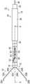
图1A是表示夹具主体的两个臂部处于打开状态的本发明的夹具处置器具的外观的一实施方式的部分侧视图。1A is a partial side view showing an embodiment of the appearance of the clip treatment tool of the present invention in which both arms of the clip main body are in an open state.
图1B是沿着图1A的A-A点划线的剖视图。FIG. 1B is a cross-sectional view taken along the dashed line A-A in FIG. 1A .
图2A是表示从其他方向观看图1A所示的夹具处置器具时的外观的一实施方式的部分侧视图。2A is a partial side view showing an embodiment of the appearance of the clip treatment tool shown in FIG. 1A when viewed from another direction.
图2B是沿着图2A的B-B点划线的剖视图。FIG. 2B is a cross-sectional view taken along the dot-dash line B-B of FIG. 2A .
图3是表示夹具主体的外观的一实施方式的立体图。FIG. 3 is a perspective view showing an embodiment of the appearance of the jig main body.
图4是表示图1A的压管的开口部的外观的放大图。FIG. 4 is an enlarged view showing the appearance of the opening of the pressure tube of FIG. 1A .
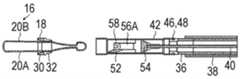
图5A是表示夹具主体锁定在紧固环上的状态的本发明的夹具处置器具的外观的一实施方式的部分侧视图。5A is a partial side view showing one embodiment of the appearance of the clip treatment tool of the present invention in a state where the clip body is locked to the fastening ring.
图5B是沿着图5A的A-A点划线的剖视图。FIG. 5B is a cross-sectional view taken along the dashed line A-A in FIG. 5A .
图6A是表示从其他方向观看图5A所示的夹具处置器具时的外观的一实施方式的部分侧视图。6A is a partial side view showing an embodiment of the appearance of the clip treatment tool shown in FIG. 5A when viewed from another direction.
图6B是沿着图6A的B-B点划线的剖视图。FIG. 6B is a cross-sectional view taken along the dashed line B-B in FIG. 6A .
图7A是表示从夹具主体分离连结部件的状态的本发明的夹具处置器具的外观的一实施方式的部分侧视图。7A is a partial side view showing an embodiment of the appearance of the clip treatment tool of the present invention in a state in which the connecting member is separated from the clip main body.
图7B是沿着图7A的A-A点划线的剖视图。FIG. 7B is a cross-sectional view taken along the dashed line A-A in FIG. 7A .
图8A是表示从其他方向观看图7A所示的夹具处置器具时的外观的一实施方式的部分侧视图。8A is a partial side view showing an embodiment of the appearance of the clip treatment tool shown in FIG. 7A when viewed from another direction.
图8B是沿着图8A的B-B点划线的剖视图。FIG. 8B is a cross-sectional view taken along the dashed line B-B in FIG. 8A .
图9A是表示夹具单元和压管分离的状态的本发明的夹具处置器具的外观的一实施方式的部分侧视图。9A is a partial side view showing an embodiment of the appearance of the clip treatment tool of the present invention in a state in which the clip unit and the pressure tube are separated.
图9B是沿着图9A的A-A点划线的剖视图。FIG. 9B is a cross-sectional view taken along the dashed line A-A in FIG. 9A .
图10A是表示从其他方向观看图9A所示的夹具处置器具时的外观的一实施方式的部分侧视图。10A is a partial side view showing an embodiment of the appearance of the clip treatment tool shown in FIG. 9A when viewed from another direction.
图10B是沿着图10A的B-B点划线的剖视图。FIG. 10B is a cross-sectional view taken along the dashed line B-B of FIG. 10A .
图11是沿着图7B的C-C点划线的剖视图。FIG. 11 is a cross-sectional view taken along the chain line C-C in FIG. 7B .
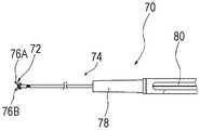
图12是表示扣锁钳的顶端部分的结构的一实施方式的侧视图。12 is a side view showing an embodiment of the structure of the distal end portion of the locking forceps.
图13是表示从图11所示的夹具主体锁定在紧固环的状态解除夹具主体和紧固环的锁定的状态的第一实施方式的剖视图。13 is a cross-sectional view of the first embodiment showing a state in which the clamp body and the clamp ring are released from the state in which the clamp body shown in FIG. 11 is locked to the clamp ring.
图14是表示圈套器部件的顶端部分的结构的一实施方式的侧视图。14 is a side view showing an embodiment of the configuration of the distal end portion of the snare member.
图15是表示从图11所示的夹具主体锁定在紧固环的状态解除夹具主体和紧固环的锁定的状态的第二实施方式的剖视图。15 is a cross-sectional view of the second embodiment showing a state in which the clamp body and the clamp ring are released from the state in which the clamp body shown in FIG. 11 is locked to the clamp ring.
具体实施方式Detailed ways
下面,根据附图所示的优选的实施方式而对本发明的夹具处置器具进行详细的说明。Hereinafter, the clip treatment tool of the present invention will be described in detail based on preferred embodiments shown in the accompanying drawings.
图1A是表示夹具主体的两个臂部处于打开状态的本发明的夹具处置器具的外观的一实施方式的部分侧视图,图1B是沿着图1A的A-A点划线的剖视图。图2A是表示从其他方向观看图1A所示的夹具处置器具时的外观的一实施方式的部分侧视图,图2B是沿着图2A的B-B点划线的剖视图。1A is a partial side view showing an embodiment of the appearance of the clip treatment tool of the present invention in which both arms of the clip main body are opened, and FIG. 1B is a cross-sectional view taken along the dot-dash line A-A in FIG. 1A . 2A is a partial side view showing an embodiment of the appearance of the clip treatment tool shown in FIG. 1A when viewed from another direction, and FIG. 2B is a cross-sectional view taken along the dashed line B-B in FIG. 2A .
在本实施方式中,将第一方向设为夹具主体的两个臂部对置的方向(垂直于图1B的纸面的方向),将第二方向设为与第一方向及压管的轴方向的双方正交的方向(垂直于图1A的纸面的方向)。此外,在夹具处置器具中,将处置部一侧设为顶端侧,将操作者一侧设为基端侧。In the present embodiment, the first direction is the direction in which the two arms of the clamp main body face each other (the direction perpendicular to the paper surface of FIG. 1B ), and the second direction is the first direction and the axis of the pressing tube Both directions are orthogonal to each other (the direction perpendicular to the paper surface of FIG. 1A ). In addition, in the clip treatment tool, the treatment portion side is referred to as the distal end side, and the operator side is referred to as the proximal end side.
另外,在所有的附图中,为了容易理解,本实施方式中的各构成要素的厚度及长度等尺寸根据需要而适当地从实际尺寸变更。In addition, in all the drawings, in order to facilitate understanding, dimensions such as thickness and length of each component in the present embodiment are appropriately changed from actual dimensions as necessary.
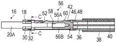
图1A、图1B、图2A及图2B所示的夹具处置器具10包括夹具单元12、处置器具主体14。夹具处置器具10由操作者的操作例如从设置在内窥镜的操作部的处置器具插入口插入,从插入到患者的体腔内的内窥镜的插入部的顶端面所设置的处置器具导出口突出来通过夹具单元12对处置部进行结扎。The
夹具单元12包括夹具主体16和紧固环18。The
图3是表示夹具主体的外观的一实施方式的立体图。FIG. 3 is a perspective view showing an embodiment of the appearance of the jig main body.
如图3所示,夹具主体16包括互相对置且开闭的两个臂部及翻折部22,该两个臂部由第一臂部20A及第二臂部20B构成,该翻折部22用于将两个臂部2 0A、20B的基端部连接。As shown in FIG. 3 , the jig
两个臂部20A及臂部20B和翻折部22分别以在第一臂部20A和翻折部22 之间及第二臀部20B和翻折部22之间弯曲的方式一体形成。此外,从第二方向观看翻折部22时的形状是大致C字形状。两个臂部20A及20B互相对置,并且延伸为在外力不被施加的状态下,随着从基端侧朝向顶端侧而互相离开。The two
第一臂部20A从基端侧依序包括第一凸部24A、第一凹部26A以及第一爪部 28A。The
第一凸部24A形成在第一臂部20A的基端部和第一凹部26A之间。第一凸部24A包括倾斜部和平坦部,该倾斜部形成为在第一臂部20A的宽度方向(第二方向)的两端部随着从基端侧朝向顶端侧而宽度方向的大小(尺寸)变大,该平坦部设置在倾斜部的顶端侧且宽度方向的大小为一定。The first
第一凹部26A形成在第一凸部24A和第一爪部28A之间。第一凹部26A形成为在第一臂部20A的宽度方向的两端部宽度方向的大小小于第一凸部24A的平坦部及第一爪部28A的宽度方向的大小。此外,第一凹部26A形成为第一臂部 20A的延伸方向的长度稍微长于紧固环18的轴方向的大小。The first
第一爪部28A形成在第一臂部20A的顶端部。第一爪部28A通过向第二臂部20B的方向以一定角度弯折第一臂部20A的顶端部而形成。The
第二臂部20B的结构与第一臂部20A同样,即包括第二凸部24B、第二凹部 26B以及第二爪部28B,该第二凸部24B、第二凹部26B以及第二爪部28B分别形成在对应于第一臂部20A的第一凸部24A、第一凹部26A以及第一爪部28A的位置上。The structure of the
第一凸部24A及第二凸部24B是将紧固环18引导至第一凹部26A及第二凹部26B的部分。第一凹部26A及第二凹部26B是与紧固环18嵌合的部分。第一爪部28A及第二爪部28B是夹着处置部而进行结扎的部分。The first
接着,如图1B及图2B所示,紧固环18包括紧固环主体30、用来将紧固环 18安装在压管42的安装部32。紧固环主体30及安装部32形成为一体。Next, as shown in FIGS. 1B and 2B , the tightening
紧固环主体30是在紧固环18安装在压管42时从压管42的顶端部向顶端侧突出的部分。紧固环主体30的外径形成为与压管42的顶端部的外径大致相同。此外,紧固环主体30的顶端部的内周面沿着全周形成有倾斜部,该倾斜部形成为随着从顶端侧朝向基端侧而内径逐渐变小。The fastening ring
安装部32设置为从紧固环主体30的基端部延伸至基端侧,并是从压管42 的顶端部向内部插入的部分。安装部32的外径形成为稍微小于压管42的顶端部的内径。The
如图13及图2B所示,紧固环18在夹具主体16锁定在紧固环18之前的状态下,就是说,在两个臂部20A、20B处于打开状态的情况下,安装在夹具主体1 6的两个臂部20A、20B上。更详细而言,紧固环18安装在比第一臂部20A的第一凸部24A及第二臂部20B的第二凸部24B的基端部靠近基端侧。As shown in FIGS. 13 and 2B , the
紧固环18起如下作用,即,随着夹具主体16相对于紧固环18从基端侧向顶端侧移动而打开两个臂部20A、20B,并且随着夹具主体16相对于紧固环18 从顶端侧向基端侧移动而闭合两个臂部20A、20B。The tightening
构成夹具单元12的夹具主体16及紧固环18例如由不锈钢、钛、钴铬合金等材料形成。因此,即使在将夹具单元12留置在患者的体腔内之后,该患者也能够就诊MRI(磁共振成像)。The clamp
接着,处置器具主体14具备插入部34和未图示的操作部。Next, the treatment tool
插入部34具备线圈护套36、管护套38、操作线40、压管42以及连结部件4 4。The
线圈护套36及管护套38是具有挠性的管,例如,由PTFE(聚四氟乙烯)等的氟树脂、或HDPE(高密度聚乙烯)等的树脂材料形成。线圈护套36插通在管护套 38内部。如图1B及图2B所示,在线圈护套36的顶端部的外周面上沿着全周形成有凹部46。The
接着,操作线40例如由金属制的单线或捻线形成。操作线40以可沿着线圈护套36的轴方向移动的方式插通在线圈护套36内部。Next, the
操作线40通过操作者操作夹具处置器具10的操作部,在线圈护套36内向顶端侧或基端侧移动。就是说,能够将操作线40从基端侧向顶端侧挤出,或者将操作线40从顶端侧向基端侧拉动。The
接着,压管42是筒状,例如由不锈钢、钛、钴铬合金等材料形成。Next, the
压管42的基端部及顶端部的内径及外径形成为大于轴方向中央部的内径及外径。如图1B及图2B所示,在压管42的基端侧的内周面上沿着全周形成有与线圈护套36的凹部46相对应的凸部48。此外,压管42的基端部的内径形成为稍微大于线圈护套36的顶端部的外径。压管42的基端部压入在线圈护套36 的顶端部,压管42的凸部48和线圈护套36的凹部46嵌合,从而压管42的基端部安装在线圈护套36的顶端部。此外,在压管42的顶端部上,紧固环18的安装部32从压管42的顶端部插入到内部,从而以可拆装的方式安装有紧固环18。The inner diameter and outer diameter of the base end portion and the distal end portion of the
压管42起随着夹具主体16相对于压管42从顶端侧向基端侧移动而将夹具主体16容纳在其内部的作用。The
图4是表示图1A的压管的开口部的外观的放大图。FIG. 4 is an enlarged view showing the appearance of the opening of the pressure tube of FIG. 1A .
如图4所示,压管42的外侧面形成有向其轴方向延伸的至少一个开口部50。开口部50在压管42的轴方向中央部上从基端侧向顶端侧以直线状延伸。开口部50从顶端侧依序包括第一开口区域50A、第二开口区域50B以及第三开口区域50C。As shown in FIG. 4 , at least one
第一开口区域50A包括开口部50的延伸方向的中央部及比中央部靠近顶端侧的开口区域。第一开口区域50A中央部的宽度方向上的大小形成为大于比中央部靠近顶端侧的宽度方向上的大小。The
第二开口区域50B是形成在第一开口区域50A的基端侧,就是说,形成在第一开口区域50A和第三开口区域之间的开口区域。第三开口区域50C是形成在比第二开口区域50B靠近基端侧的开口区域。第二开口区域50B及第三开口区域50C的宽度方向上的大小形成为与比第一开口区域50A的中央部靠近顶端侧的宽度方向上的大小大致相同。The
此外,如图4所示,压管42的外侧面在轴方向的中央部形成有开口部52,该开口部52从第一开口区域的顶端部进一步朝向顶端侧以与轴方向有一定角度的方式倾斜并延伸。In addition, as shown in FIG. 4 , an
接着,如图1B所示,连结部件44包括连结部件主体54和夹持部56,例如,由具有活体适合性的各种树脂形成。连结部件44容纳在压管42内部。在连结部件主体54的基端部,即连结部件44的基端部上固定有操作线40的顶端部。Next, as shown in FIG. 1B , the connecting
夹持部56是作为将夹具主体16的翻折部22以可拆装的方式连接的顶端部的部分,设置在连结部件主体54的顶端侧,并且连结部件主体54和夹持部56 形成为一体。夹持部56包括第一夹持部件56A及第二夹持部件56B,第一夹持部件56A及第二夹持部件56B以互相对置的方式从连结部件主体54的顶端部向顶端侧并联延伸。此外,第一夹持部件56A和第二夹持部件56B以在第二方向上隔着一定间隔的方式配置。第一夹持部件56A和第二夹持部件56B的间隔形成为与夹具主体16的翻折部22的宽度方向上的大小相同或稍微长。The clamping
此外,第一夹持部件56A的延伸方向的长度形成为稍微短于压管42的开口部50中央部的轴方向上的长度。第一夹持部件56A的宽度方向(第一方向)的大小形成为稍微小于压管42的开口部50中央部(第一开口区域50A)的宽度方向 (第一方向)上的大小。此外,第一夹持部件56A的外侧面朝向压管42的开口部5 0的方向。Further, the length in the extending direction of the first holding
如图1B及图2B所示,第一夹持部件56A在与顶端侧的第二夹持部件56B 对置的内侧面上包括对夹具主体16的翻折部22进行卡止的卡止部58。卡止部 58从第一夹持部件56A向第二夹持部件56B的方向突出,并且包括倾斜部及平坦部,该倾斜部形成为第二方向上的高度随着从基端侧朝向顶端侧而变高,该平坦部设置在倾斜部的顶端侧且高度一定。从第二方向观看卡止部58时的形状与从第二方向观看夹具主体16的翻折部22时的形状同样,即是大致C字形状,并且其外径形成为稍微小于从第二方向观看翻折部22时由翻折部22形成的空间的形状的内径。As shown in FIGS. 1B and 2B , the first gripping
通过第一夹持部件56A及第二夹持部件56B从第二方向的两侧夹持夹具主体16的翻折部22,并且从第一夹持部件56A向第二夹持部件56B的方向突出的卡止部58插入在从第二方向观看翻折部22时由翻折部22形成的空间中,翻折部22和卡止部58互相卡止,连结部件44和夹具主体16以可拆装的方式互相卡止。The folded
如上所述,连结部件44的顶端部与翻折部22以可拆装的方式卡止,连结部件44的基端部固定有操作线40的顶端部,从而通过连结部件44而连结夹具主体16和操作线40。As described above, the distal end portion of the connecting
连结部件44随着操作线40从基端侧向顶端侧移动而在压管42内从基端侧向顶端侧移动,并且随着操作线40从顶端侧向基端侧移动而在压管42内从顶端侧向基端侧移动。The connecting
此外,连结部件44在第一夹持部件56A和连结部件主体54之间的外侧面上包括从压管42的开口部50露出其至少一部分的露出部60。连结部件44的露出部60的宽度方向(第一方向)的大小形成为稍微小于比压管42的开口部50 的中央部靠近顶端侧(第一开口区域)、第二开口区域50B、第三开口区域50C及开口部52的宽度方向上的大小。Further, the connecting
在将连结部件44从压管42的顶端部插入在内部的情况下,压管42的外侧面的开口部52成为将连结部件44插入在压管42内时的引导槽。露出部60沿着开口部52的延伸方向从顶端侧向基端侧移动,引导至第一开口区域50A的顶端部。When the connecting
本实施方式的露出部60是针形状的突起,并且在连结部件44在压管42内向轴方向往复移动时在压管42的开口部50(第一开口区域50A、第二开口区域5 0B及第三开口区域50C)内同样地往复移动。就是说,露出部60随着连结部件44 从基端侧向顶端侧移动而在压管42的开口部50内沿着压管42的轴方向从基端侧向顶端侧移动,并且随着连结部件44从顶端侧向基端侧移动而在压管42 的开口部50内沿着压管42的轴方向从顶端侧向基端侧移动。露出部60也可以被称为在连结部件44往复移动时防止连结部件44的旋转等的引导部件,并且比开口部50的第一开口区域50A中央部靠近顶端侧的开口区域、第二开口区域 50B及第三开口区域50C成为其引导槽。The exposed
接着,处置器具主体14的操作部包括未图示的操作部主体及滑动件等。Next, the operation part of the treatment tool
操作部主体的顶端部安装在线圈护套36的基端部。The distal end portion of the operating portion main body is attached to the proximal end portion of the
滑动件是使操作线40相对于线圈护套36向顶端侧或基端侧移动的部分,以可相对于操作部主体向顶端侧或基端侧滑动的方式设置,并且滑动件的顶端部固定有操作线40的基端部。The slider is a portion that moves the
通过操作者操作夹具处置器具10的操作部,滑动件相对于操作部主体从顶端侧向基端侧移动,使得操作线40从顶端侧向基端侧移动,并且滑动件相对于操作部主体从基端侧向顶端侧移动,使得操作线40从基端侧向顶端侧移动。When the operator operates the operation portion of the
下面,对夹具处置器具10的动作进行说明。Next, the operation of the
首先,说明通过夹具单元12对处置部进行结扎的情况的动作。在以下说明中,以未图示的内窥镜的插入部已插入在患者的体腔内为前提。First, the operation when the treatment portion is ligated by the
首先,通过由操作者的操作,从未图示的内窥镜的处置器具插入口插入夹具处置器具10的插入部34,使夹具处置器具10的插入部34的顶端部,更正确地说,使夹具单元12的顶端部从内窥镜的处置器具导出口突出。First, the
接着,通过操作者操作夹具处置器具10的操作部,操作线40从基端侧向顶端侧移动。Next, when the operator operates the operation portion of the
随着操作线40从基端侧向顶端侧移动,而连结部件44及夹具主体16从基端侧向顶端侧移动,如图1A、图1B、图2A及图2B所示,夹具主体16的两个臂部 20A、20B成为打开状态。As the
接着,通过由操作者的操作,夹具处置器具10的插入部34从基端侧向顶端侧移动,打开状态的两个臂部20A、20B的顶端部压接在处置部。Next, the
接着,在打开状态的两个臂部20A、20B的顶端部压接在处置部的状态下,通过操作者操作夹具处置器具10的操作部,操作线40从顶端侧向基端侧移动。Next, when the operator operates the operation part of the
随着操作线40从顶端侧向基端侧移动,而连结部件44从顶端侧向基端侧移动,连结部件44的露出部60沿着压管42的开口部50从顶端侧向基端侧移动。此外,随着连结部件44从顶端侧向基端侧移动,而夹具主体16从顶端侧向基端侧移动,两个臂部20A、20B通过紧固环18的顶端侧端部向互相接近的方向被压紧而弹性变形,从而两个臂部20A、20B从打开状态逐渐闭合。As the
在夹具主体16锁定在紧固环18之前的状态下,能够随着连结部件44从基端侧向顶端侧移动,就是说,随着露出部60在压管42的第一开口区域50A内从基端侧向顶端侧移动而两个臂部20A、20B打开,并且随着连结部件44从顶端侧向基端侧移动,就是说,随着露出部60在压管42的第一开口区域50A内从顶端侧向基端侧移动而两个臂部20A、20B闭合。In a state before the
随着连结部件44从顶端侧向基端侧移动,就是说,随着露出部60在压管42 的第一开口区域50A内从顶端侧向基端侧移动,而夹具主体16从顶端侧向基端侧移动,两个臂部20A、20B通过紧固环18的顶端侧端部向互相接近的方向被压紧而弹性变形,两个臂部20A、20B从打开状态(完全打开状态)逐渐闭合而最终成为闭合状态(完全闭合状态)。As the connecting
另一方面,随着连结部件44从基端侧向顶端侧移动,就是说,随着露出部60 在第一开口区域50A内从基端侧向顶端侧移动,而夹具主体16从基端侧向顶端侧移动,并且两个臂部20A、20B由于弹性力而从闭合状态逐渐打开而最终成为打开状态。On the other hand, as the connecting
在夹具主体16向顶端侧或基端侧移动的情况下,两个臂部20A、20B的宽度方向的两端部和紧固环主体30的顶端部的内周面点接触,两个臂部20A、20B沿着紧固环主体30的顶端部的内周面而滑动。When the clip
两个臂部20A、20B的第一凸部24A及第二凸部24B的倾斜部及紧固环主体 30的顶端部的内周面的倾斜部在两个臂部20A、20B沿着紧固环主体30的顶端部的内周面而滑动的情况下,起如下作用,即,减轻两个臂部20A、20B和紧固环主体30之间的摩擦阻力,且使夹具主体16相对于紧固环18容易向顶端侧或基端侧移动。The inclined portions of the first
如上所述,在夹具主体16锁定在紧固环18之前的状态下,能够开闭两个臂部20A、20B来通过两个臂部20A、20B的第一爪部28A及第二爪部28B重新抓住处置部,因此能够正确地抓住目标的处置部。As described above, in the state before the
接着,在通过两个臂部20A、20B的第一爪部28A及第二爪部28B抓住处置部的状态下,操作线40从顶端侧向基端侧进一步移动。Next, the
随之,连结部件44及夹具主体16从顶端侧向基端侧进一步移动,如图5A、图5B、图6A及图6B所示,在露出部60移动至第一开口区域50A和第二开口区域50B的边界时,紧固环18和两个臂部20A、20B卡止,两个臂部20A、20B成为闭合状态。Following this, the connecting
更详细而言,连结部件44及夹具主体16从顶端侧向基端侧进一步移动,两个臂部20A、20B的凹部,就是说,第一凹部26A及第二凹部26B的基端侧的端部移动至超过紧固环18的基端侧端部的位置时,如图11所示,两个臂部20A、20B 由于弹性力而向互相离开的方向(第一方向)移动,如图5B所示,紧固环18嵌合在两个臂部20A、20B的凹部26A、26B而卡止,从而两个臂部20A、20B成为闭合状态。More specifically, when the connecting
由此,如图5A、图5B、图6A及图6B所示,夹具主体16以两个臂部20A、20B 闭合的状态锁定在紧固环18,通过两个臂部20A、20B的第一爪部28A及第二爪部28B对处置部进行结扎。As a result, as shown in FIGS. 5A , 5B, 6A and 6B, the
接着,在夹具主体16锁定在紧固环18的状态下,就是说,在通过两个臂部2 0A、20B的第一爪部28A及第二爪部28B对处置部进行结扎的状态下,操作线40 从顶端侧向基端侧进一步移动。Next, in a state in which the
随之,连结部件44及夹具主体16从顶端侧向基端侧进一步移动,连结部件 44的露出部60在第二开口区域50B内从顶端侧向基端侧移动。Accordingly, the connecting
随着露出部60在第二开口区域50B内从顶端侧向基端侧移动,而连结部件 44的卡止部58的倾斜部越过夹具主体16的翻折部22的基端侧端部,从顶端侧向基端侧移动,第一夹持部件56A的顶端部从压管42的开口部50中央部(第一开口区域)向压管42外侧移动。就是说,第一夹持部件56A的顶端部从开口部 50的中央部向压管42外侧被挤出。As the exposed
露出部60在第二开口区域50B内移动时由作为引导槽的第二开口区域50B 限制旋转,因此连结部件44的旋转被限制。由此,以第一夹持部件56A的位置和压管42的开口部50的位置一致的方式进行定位,第一夹持部件56A的顶端部能够从压管42的开口部50的中央部(第一开口区域)向压管42外侧移动。When the exposed
连结部件44及夹具主体16从顶端侧向基端侧进一步移动,如图7A、图7B、图8A及图8B所示,露出部60从第二开口区域50B向第三开口区域50C内移动,卡止部58超过翻折部22的基端侧的端部,翻折部22和卡止部58的卡止被解除,夹具主体16和连结部件44分离。The connecting
在翻折部22和卡止部58卡止的状态下,连结部件44从顶端侧向基端侧移动的情况下,卡止部58的倾斜部的倾斜面与翻折部22的基端部的第一夹持部件56A侧端部线接触,卡止部58的倾斜部沿着翻折部22的基端部的第一夹持部件56A侧端部而滑动。When the connecting
卡止部58的倾斜部在卡止部58沿着翻折部22的基端部的第一夹持部件5 6A侧端部而滑动的情况下,起如下作用,即,减轻卡止部58的倾斜部和翻折部 22之间的摩擦阻力,且使卡止部58相对于翻折部22容易从顶端侧向基端侧移动。The inclined portion of the locking
接着,在夹具主体16和连结部件44分离的状态下,操作线40从基端侧向顶端侧移动。Next, in a state in which the
随着操作线40从基端侧向顶端侧移动,而连结部件44从基端侧向顶端侧移动,连结部件44的顶端部与夹具主体16的翻折部22的基端部抵接。随着连结部件44从基端侧向顶端侧进一步移动,而通过连结部件44向顶端侧挤出夹具主体16的基端部,如图9A、图9B、图10A及图10B所示,锁定有夹具主体16 的紧固环18和压管42分离。由此,在处置部通过夹具单元12结扎的状态下,夹具单元12留置在处置部。As the
然后,通过由操作者的操作,在夹具处置器具10的插入部34插入在内窥镜内部的状态下,从患者的体腔内拉拔而取出内窥镜的插入部。另外,在对多个处置部进行结扎的情况下,反复进行上述动作。Then, the
接着,对从处置部拆卸夹具单元12时的动作进行说明。Next, the operation when the
首先,对使用扣锁钳等扣锁部件拆卸夹具单元12时的动作进行说明。First, the operation when the
图12是表示扣锁钳的顶端部分的结构的一实施方式的侧视图。图12所示的扣锁钳70具备扣锁部72、插入部74、未图示的操作部。扣锁部72安装在插入部74的顶端部,操作部安装在插入部74的基端部。12 is a side view showing an embodiment of the structure of the distal end portion of the locking forceps. The locking
扣锁部72包括一对爪部件76A、76B。爪部件76A、76B通过操作者操作操作部而开闭。爪部件76A、76B从基端侧向顶端侧延伸,在其扣锁面处于闭合状态的情况下,互相对置地配置。The
插入部74具备护套78和操作线80。The
操作线80以可进退的方式插通在护套78内。扣锁部72安装在护套78的顶端部,扣锁部72的爪部件76A、76B的基端部固定有操作线80的顶端部。The
在通过操作者操作操作部,操作线80从顶端侧向基端侧移动时,一对爪部件76A、76B成为闭合状态(扣锁状态)。另一方面,在操作线80从基端侧向顶端侧移动时,一对爪部件76A、76B成为打开状态(非扣锁状态)。When the operation part is operated by the operator to move the
在拆卸夹具单元12的情况下,首先,通过由操作者的操作,从未图示的内窥镜的处置器具插入口插入扣锁钳70的插入部74,扣锁钳70的插入部74的顶端部,更正确而言,扣锁钳70的顶端部的扣锁部72从内窥镜的处置器具导出口突出。When the
接着,在紧固环18和压管42分离的状态下,就是说,在夹具单元12对处置部进行结扎而留置的状态下,通过操作者操作扣锁钳70的操作部,扣锁钳70的扣锁部72的爪部件76A、76B成为打开状态。接着,打开状态的扣锁部72的爪部件76A、76B逐渐闭合,紧固环18通过扣锁部的爪部件76A、76B从两个臂部20A、 20B所对置的方向(第一方向)的外周面两侧抓住而压紧,从第一方向的外周面两侧挤破。Next, in a state in which the
紧固环18从第一方向的外周面两侧挤破,通过紧固环18的内周面而两个臂部20A、20B互相接近,如图13的夹具单元12的剖视图所示,两个臂部20A、20 B的凹部,就是说,第一凹部26A及第二凹部26B的基端侧端部移动至与紧固环 18的内周面抵接的位置,夹具主体16和紧固环18的锁定被解除。The
接着,在夹具主体16和紧固环18的锁定被解除的状态下,紧同环18相对于夹具主体16从顶端侧向基端侧移动。例如,在通过扣锁钳70的扣锁部72的爪部件76A、76B而夹持紧固环18的状态下,随着通过操作者的操作来扣锁钳70 从顶端侧向基端侧移动,而紧固环18相对于夹具主体16从顶端侧向基端侧移动。Next, in a state in which the lock of the
随着紧固环18相对于夹具主体16从顶端侧向基端侧移动,而两个臂部20A 、20B由于弹性力而从闭合状态逐渐打开而最终成为打开状态。由此,夹具单元1 2从处置部拆卸。As the
然后,通过由操作者的操作,在扣锁钳70的插入部74插入在内窥镜内部的状态下,从患者的体腔内拉拔而取出内窥镜的插入部。例如,在通过扣锁钳70的扣锁部72的爪部件76A、76B夹持紧固环18的状态下,从患者的体腔内拉拔内窥镜的插入部,从处置部拆卸的夹具单元12也同时取出到患者的体腔外。另外,在从处置部拆卸多个夹具单元12的情况下,反复进行所述动作。Then, the
接着,对使用圈套器部件拆卸夹具单元12时的动作进行说明。Next, the operation when the
图14是表示圈套器部件的顶端部分的结构的一实施方式的侧视图。图14 所示的圈套器部件82具备套圈部84、插入部86以及未图示的操作部。套圈部8 4安装在后述的插通在插入部86内部的操作线90的顶端部,操作部安装在插入部86的基端部。14 is a side view showing an embodiment of the configuration of the distal end portion of the snare member. The
套圈部84通过弯折线而形成。线的弯折部朝向顶端侧。套圈部84通过操作者操作操作部,而其套圈直径缩放。The
插入部86具备护套88和操作线90。The
操作线90以可进退的方式插通在护套内。套圈部84安装在护套88的顶端部,并且套圈部84的线两端部固定在操作线90的顶端部。The
当通过操作者操作操作部而操作线90从顶端侧向基端侧移动时,套圈部84 容纳在护套88内而套圈部84的套圈直径缩小。另一方面,当操作线90从基端侧向顶端侧移动时,套圈部84从护套88的顶端部突出而套圈部84的套圈直径放大。When the
在拆卸夹具单元12的情况下,首先,通过由操作者的操作,从未图示的内窥镜的处置器具插入口插入圈套器部件82的插入部86,圈套器部件82的插入部 86的顶端部,更正确而言,圈套器部件82的顶端部的套圈部84从内窥镜的处置器具导出口突出。When the
接着,在紧固环18和压管42分离的状态下,就是说,在夹具单元12对处置部进行结扎而留置的状态下,通过操作者操作圈套器部件82的操作部而放大圈套器部件82的套圈部84的套圈直径。接着,套圈部84的所放大的套圈直径逐渐缩小,两个臂部20A、20B由套圈部84夹紧,从两个臂部20A、20B对置的方向 (第一方向)的外侧面两侧压紧,向互相接近的方向移动。Next, in a state in which the
两个臂部20A、20B被夹紧而从第一方向的外侧面两侧压紧,两个臂部20A、2 0B互相接近,如图15的夹具单元12的剖视图所示,两个臂部20A、20B的凹部,就是说,第一凹部26A及第二凹部26B的基端侧的端部移动至与紧固环18的内周面抵接的位置,从而夹具主体16和紧固环18的锁定被解除。The two
接着,在夹具主体16和紧固环18的锁定被解除的状态下,夹具主体16相对于紧固环18从基端侧向顶端侧移动。例如,在通过圈套器部件82的套圈部84 而两个臂部20A、20B夹紧的状态下,随着通过操作者的操作而圈套器部件82从基端侧向顶端侧移动,而夹具主体16相对于紧固环18从基端侧向顶端侧移动。Next, in a state in which the lock between the
随着夹具主体16相对于紧固环18从基端侧向顶端侧移动,而两个臂部20A、 20B由于弹性力而从闭合状态逐渐打开而最终成为打开状态。由此,夹具单元12 从处置部拆卸。As the
然后,通过由操作者的操作而在圈套器部件82的插入部86插入到内窥镜内部的状态下,从患者的体腔内拉拔而取出内窥镜的插入部。例如,在通过圈套器部件82的套圈部84而两个臂部20A、20B夹紧的状态下,从患者的体腔内拉拔内窥镜的插入部,从处置部拆卸的夹具单元12也同时取出到患者的体腔外。另外,在从处置部拆卸多个夹具单元12的情况下,反复进行所述动作。Then, the
在夹具处置器具10中,在直到通过夹具单元12对处置部进行结扎为止的期间,能够通过两个臂部20A、20B重新抓住处置部,并且在通过夹具单元12对处置部进行结扎之后,夹具主体16和紧固环18锁定,因此能够确实地保持通过夹具单元12对处置部进行结扎的状态。此外,在夹具单元12留置在处置部之后,能够以任意的时机解除夹具主体16和紧固环18的锁定而从处置部拆卸夹具单元12。In the
另外,从第二方向观看夹具主体16的翻折部22及连结部件44的卡止部58 时的形状不限定于大致C字形状,只要能够将翻折部22和卡止部58卡止,就对其形状没有特别限定。In addition, the shape of the folded
将夹具主体16和紧固环18卡止的方法不限定于两个臂部20A、20B的第一凹部26A及第二凹部26B和紧固环18的嵌合,只要能够将两者卡止,就对其卡止方法没有特别限定。The method of locking the
就压管42的开口部50而言,只要连结部件44的露出部60的至少一部分露出,而且第一夹持部件56A的顶端侧能够从开口部50向压管42外侧移动,就对其形状及大小等没有特别限定。The shape of the opening
将夹具主体16和连结部件44卡止的构件不限定于卡止部58,只要能够将两者卡止,就对其卡止构件没有特别限定。The member for locking the
虽然只在连结部件44的第一夹持部件56A的顶端侧设置有卡止部58,但是也可以在第二夹持部件56B的顶端侧设置卡止部。在此情况下,以第二夹持部件 56B的顶端侧能够向压管42外侧挤出的方式,还在压管42的外侧面上与第二夹持部件56B的外侧面对置的位置上设置包括与开口部50的中央部同样的开口区域的开口部。Although the locking
连结部件44的露出部60只要从压管42的开口部50露出其至少一部分,就对其形状及大小等没有特别限定。The exposed
以上,对本发明进行详细的说明,本发明不限定于上述实施方式,在不脱离本发明主旨的范围内能够进行各种改进及变更是显而易见的。As mentioned above, although this invention was demonstrated in detail, this invention is not limited to the said embodiment, It is clear that a various improvement and change can be added in the range which does not deviate from the summary of this invention.
符号说明Symbol Description
10 夹具处置器具10 Fixture handling equipment
12 夹具单元12 Fixture unit
14 处置器具主体14 Disposal of the main body of the appliance
16 夹具主体16 Fixture body
18 紧固环18 Fastening ring
20A 第一臂部20A first arm
20B 第二臂部20B Second arm
22 翻折部22 Folding part
24A 第一凸部24A First convex part
26A 第一凹部26A First recess
28A 第一爪部28A first claw
24B 第二凸部24B Second convex part
26B 第二凹部26B Second recess
28B 第二爪部28B Second claw
30 紧固环主体30 Fastening ring body
32 安装部32 Installation part
34、74、86 插入部34, 74, 86 Insert
36 线圈护套36 Coil jacket
38 管护套38 Tube Sheath
40、80、90 操作线40, 80, 90 operating lines
42 压管42 pressure tube
44 连结部件44 Connecting parts
46 凹部46 Recess
48 凸部48 Convex
50、52 开口部50, 52 Opening
50A 第一开口区域50A first open area
50B 第二开口区域50B Second open area
50C 第三开口区域50C third opening area
54 连结部件主体54 Connection part main body
56 夹持部56 Clamping part
56A 第一夹持部件56A First clamping part
56B 第二夹持部件56B Second clamping part
58 卡止部58 Locking part
60 露出部60 exposed
70 扣锁钳70 Snap Lock Pliers
72 扣锁部72 Buckle
76A、76B 爪部件76A, 76B Claw parts
78、88 护套78, 88 Sheath
82 圈套器部件82 Snare Parts
84 套圈部84 Ferrule Department
Claims (9)
Applications Claiming Priority (3)
| Application Number | Priority Date | Filing Date | Title |
|---|---|---|---|
| JP2017-121591 | 2017-06-21 | ||
| JP2017121591 | 2017-06-21 | ||
| PCT/JP2018/015206WO2018235404A1 (en) | 2017-06-21 | 2018-04-11 | Clip treatment tool |
Publications (2)
| Publication Number | Publication Date |
|---|---|
| CN110769765Atrue CN110769765A (en) | 2020-02-07 |
| CN110769765B CN110769765B (en) | 2022-12-30 |
Family
ID=64735606
Family Applications (1)
| Application Number | Title | Priority Date | Filing Date |
|---|---|---|---|
| CN201880039719.2AActiveCN110769765B (en) | 2017-06-21 | 2018-04-11 | Clamp treatment tool |
Country Status (5)
| Country | Link |
|---|---|
| US (1) | US11013517B2 (en) |
| EP (1) | EP3643253B1 (en) |
| JP (1) | JP6858258B2 (en) |
| CN (1) | CN110769765B (en) |
| WO (1) | WO2018235404A1 (en) |
Cited By (1)
| Publication number | Priority date | Publication date | Assignee | Title |
|---|---|---|---|---|
| CN114886497A (en)* | 2021-01-26 | 2022-08-12 | 奥林巴斯医疗株式会社 | Treatment device for endoscope |
Families Citing this family (4)
| Publication number | Priority date | Publication date | Assignee | Title |
|---|---|---|---|---|
| WO2020141345A1 (en)* | 2019-01-03 | 2020-07-09 | Olympus Corporation | A clipping device for large defects, perforations and fistulas |
| CN111481287B (en)* | 2020-04-03 | 2021-03-23 | 桐庐洲济医疗器械有限公司 | Adjustable electrocoagulator |
| WO2021210364A1 (en)* | 2020-04-17 | 2021-10-21 | 国立大学法人愛媛大学 | Clip removal device |
| CN116710000A (en)* | 2021-01-13 | 2023-09-05 | 杭州安杰思医学科技股份有限公司 | Clip device, clip instrument and clip unlocking method |
Citations (7)
| Publication number | Priority date | Publication date | Assignee | Title |
|---|---|---|---|---|
| US5766189A (en)* | 1996-02-29 | 1998-06-16 | Olympus Optical Co., Ltd. | Clip device |
| EP1604614A1 (en)* | 2003-03-17 | 2005-12-14 | Sumitomo Bakelite Co., Ltd. | Clip and clipping instrument for biological tissues |
| CN101756741A (en)* | 2008-08-29 | 2010-06-30 | Tyco医疗健康集团 | Endoscopic surgical clip applier |
| CN102076271A (en)* | 2008-05-05 | 2011-05-25 | 尼蒂外科设备有限公司 | Endoscopic compression clip and system and method for use thereof |
| CN102988095A (en)* | 2011-09-15 | 2013-03-27 | 富士胶片株式会社 | Clip unit, ligation device using the same, and method for fabricating the clip unit |
| US20140171973A1 (en)* | 2011-11-11 | 2014-06-19 | Jian Zhu | Living tissue ligation device |
| US20160100841A1 (en)* | 2014-10-09 | 2016-04-14 | Cardiomedical Gmbh | Surgical instrument |
Family Cites Families (9)
| Publication number | Priority date | Publication date | Assignee | Title |
|---|---|---|---|---|
| JPS4921173B1 (en) | 1970-01-29 | 1974-05-30 | ||
| FR2381594A1 (en) | 1977-02-24 | 1978-09-22 | Centre Techn Ind Mecanique | ELECTROCHEMICAL MACHINING PROCESS OF POLYPHASIC ALLOYS |
| DE4319829C1 (en)* | 1993-06-16 | 1994-08-25 | Lerch Karl Dieter | Set for treating vascular deformities |
| EP1670365B1 (en) | 2003-09-30 | 2018-12-05 | Boston Scientific Scimed, Inc. | Apparatus for deployment of a hemostatic clip |
| JP4910879B2 (en)* | 2007-05-22 | 2012-04-04 | 住友ベークライト株式会社 | Medical clip device, its elastic clip unit and flexible tube unit |
| JP5045485B2 (en)* | 2008-02-18 | 2012-10-10 | 日本ゼオン株式会社 | Endoscope clip attachment |
| BR112013008763B1 (en) | 2010-10-11 | 2021-02-17 | Cook Medical Technologies LLC. | medical device for engaging a tissue |
| JP5750619B2 (en) | 2013-05-07 | 2015-07-22 | オリンパス株式会社 | Clip unit |
| CN103989500B (en) | 2014-05-23 | 2015-11-18 | 南京微创医学科技有限公司 | A kind of hemostatic clamp |
- 2018
- 2018-04-11CNCN201880039719.2Apatent/CN110769765B/enactiveActive
- 2018-04-11JPJP2019525142Apatent/JP6858258B2/enactiveActive
- 2018-04-11EPEP18820282.4Apatent/EP3643253B1/enactiveActive
- 2018-04-11WOPCT/JP2018/015206patent/WO2018235404A1/ennot_activeCeased
- 2019
- 2019-12-16USUS16/714,800patent/US11013517B2/enactiveActive
Patent Citations (7)
| Publication number | Priority date | Publication date | Assignee | Title |
|---|---|---|---|---|
| US5766189A (en)* | 1996-02-29 | 1998-06-16 | Olympus Optical Co., Ltd. | Clip device |
| EP1604614A1 (en)* | 2003-03-17 | 2005-12-14 | Sumitomo Bakelite Co., Ltd. | Clip and clipping instrument for biological tissues |
| CN102076271A (en)* | 2008-05-05 | 2011-05-25 | 尼蒂外科设备有限公司 | Endoscopic compression clip and system and method for use thereof |
| CN101756741A (en)* | 2008-08-29 | 2010-06-30 | Tyco医疗健康集团 | Endoscopic surgical clip applier |
| CN102988095A (en)* | 2011-09-15 | 2013-03-27 | 富士胶片株式会社 | Clip unit, ligation device using the same, and method for fabricating the clip unit |
| US20140171973A1 (en)* | 2011-11-11 | 2014-06-19 | Jian Zhu | Living tissue ligation device |
| US20160100841A1 (en)* | 2014-10-09 | 2016-04-14 | Cardiomedical Gmbh | Surgical instrument |
Cited By (1)
| Publication number | Priority date | Publication date | Assignee | Title |
|---|---|---|---|---|
| CN114886497A (en)* | 2021-01-26 | 2022-08-12 | 奥林巴斯医疗株式会社 | Treatment device for endoscope |
Also Published As
| Publication number | Publication date |
|---|---|
| EP3643253A4 (en) | 2020-05-27 |
| WO2018235404A1 (en) | 2018-12-27 |
| EP3643253A1 (en) | 2020-04-29 |
| EP3643253B1 (en) | 2024-12-11 |
| JP6858258B2 (en) | 2021-04-14 |
| US11013517B2 (en) | 2021-05-25 |
| US20200113568A1 (en) | 2020-04-16 |
| CN110769765B (en) | 2022-12-30 |
| JPWO2018235404A1 (en) | 2020-03-26 |
Similar Documents
| Publication | Publication Date | Title |
|---|---|---|
| JP6815506B2 (en) | Clip treatment tool | |
| CN110769765B (en) | Clamp treatment tool | |
| CN110461254B (en) | Clamp treatment tool | |
| US12357318B2 (en) | Clip unit, medical instrument, and attaching method of medical instrument | |
| CN110769764B (en) | Clamp treatment tool | |
| CN107072671B (en) | Treatment tool for endoscope | |
| CN107371362B (en) | clip device | |
| CN112969418B (en) | Clamp unit and endoscope clamp | |
| CN113164176A (en) | Medical device | |
| CN113194850B (en) | Ligation device and engagement method | |
| CN114727748A (en) | Clip applier | |
| JP7303217B2 (en) | Ligating device and applicator | |
| US20210290244A1 (en) | Cartridge, clip system, and method of mounting clip | |
| CN113164174B (en) | Feeder, medical device, and method of operating medical device | |
| CN217066505U (en) | Medical device |
Legal Events
| Date | Code | Title | Description |
|---|---|---|---|
| PB01 | Publication | ||
| PB01 | Publication | ||
| SE01 | Entry into force of request for substantive examination | ||
| SE01 | Entry into force of request for substantive examination | ||
| GR01 | Patent grant | ||
| GR01 | Patent grant |