CN110763859A - A constant flow pump for flow injection analyzer - Google Patents
A constant flow pump for flow injection analyzerDownload PDFInfo
- Publication number
- CN110763859A CN110763859ACN201910876402.0ACN201910876402ACN110763859ACN 110763859 ACN110763859 ACN 110763859ACN 201910876402 ACN201910876402 ACN 201910876402ACN 110763859 ACN110763859 ACN 110763859A
- Authority
- CN
- China
- Prior art keywords
- tube
- piston ball
- piston
- positioning
- ring
- Prior art date
- Legal status (The legal status is an assumption and is not a legal conclusion. Google has not performed a legal analysis and makes no representation as to the accuracy of the status listed.)
- Granted
Links
- 238000004401flow injection analysisMethods0.000titleclaimsabstractdescription14
- 239000007788liquidSubstances0.000claimsabstractdescription68
- 238000001802infusionMethods0.000claimsabstractdescription53
- 230000005540biological transmissionEffects0.000claimsabstractdescription27
- 238000007789sealingMethods0.000claimsdescription10
- 238000003825pressingMethods0.000claimsdescription6
- 230000002572peristaltic effectEffects0.000abstractdescription6
- 238000009434installationMethods0.000description13
- 230000000694effectsEffects0.000description7
- 238000000034methodMethods0.000description5
- 238000004458analytical methodMethods0.000description4
- 230000009286beneficial effectEffects0.000description3
- 239000000243solutionSubstances0.000description3
- 238000006243chemical reactionMethods0.000description2
- 230000007423decreaseEffects0.000description2
- XLYOFNOQVPJJNP-UHFFFAOYSA-NwaterSubstancesOXLYOFNOQVPJJNP-UHFFFAOYSA-N0.000description2
- 230000002159abnormal effectEffects0.000description1
- 239000003153chemical reaction reagentSubstances0.000description1
- 230000007547defectEffects0.000description1
- 238000001514detection methodMethods0.000description1
- 238000010586diagramMethods0.000description1
- 238000012986modificationMethods0.000description1
- 230000004048modificationEffects0.000description1
- 238000005096rolling processMethods0.000description1
Images

Classifications
- G—PHYSICS
- G01—MEASURING; TESTING
- G01N—INVESTIGATING OR ANALYSING MATERIALS BY DETERMINING THEIR CHEMICAL OR PHYSICAL PROPERTIES
- G01N35/00—Automatic analysis not limited to methods or materials provided for in any single one of groups G01N1/00 - G01N33/00; Handling materials therefor
- G01N35/08—Automatic analysis not limited to methods or materials provided for in any single one of groups G01N1/00 - G01N33/00; Handling materials therefor using a stream of discrete samples flowing along a tube system, e.g. flow injection analysis
- G01N35/085—Flow Injection Analysis
- F—MECHANICAL ENGINEERING; LIGHTING; HEATING; WEAPONS; BLASTING
- F04—POSITIVE - DISPLACEMENT MACHINES FOR LIQUIDS; PUMPS FOR LIQUIDS OR ELASTIC FLUIDS
- F04B—POSITIVE-DISPLACEMENT MACHINES FOR LIQUIDS; PUMPS
- F04B43/00—Machines, pumps, or pumping installations having flexible working members
- F04B43/12—Machines, pumps, or pumping installations having flexible working members having peristaltic action
- F—MECHANICAL ENGINEERING; LIGHTING; HEATING; WEAPONS; BLASTING
- F04—POSITIVE - DISPLACEMENT MACHINES FOR LIQUIDS; PUMPS FOR LIQUIDS OR ELASTIC FLUIDS
- F04B—POSITIVE-DISPLACEMENT MACHINES FOR LIQUIDS; PUMPS
- F04B53/00—Component parts, details or accessories not provided for in, or of interest apart from, groups F04B1/00 - F04B23/00 or F04B39/00 - F04B47/00
- F04B53/14—Pistons, piston-rods or piston-rod connections
- G—PHYSICS
- G01—MEASURING; TESTING
- G01N—INVESTIGATING OR ANALYSING MATERIALS BY DETERMINING THEIR CHEMICAL OR PHYSICAL PROPERTIES
- G01N21/00—Investigating or analysing materials by the use of optical means, i.e. using sub-millimetre waves, infrared, visible or ultraviolet light
- G01N21/01—Arrangements or apparatus for facilitating the optical investigation
- G—PHYSICS
- G01—MEASURING; TESTING
- G01N—INVESTIGATING OR ANALYSING MATERIALS BY DETERMINING THEIR CHEMICAL OR PHYSICAL PROPERTIES
- G01N21/00—Investigating or analysing materials by the use of optical means, i.e. using sub-millimetre waves, infrared, visible or ultraviolet light
- G01N21/75—Systems in which material is subjected to a chemical reaction, the progress or the result of the reaction being investigated
- G01N21/77—Systems in which material is subjected to a chemical reaction, the progress or the result of the reaction being investigated by observing the effect on a chemical indicator
- G01N21/78—Systems in which material is subjected to a chemical reaction, the progress or the result of the reaction being investigated by observing the effect on a chemical indicator producing a change of colour
- G—PHYSICS
- G01—MEASURING; TESTING
- G01N—INVESTIGATING OR ANALYSING MATERIALS BY DETERMINING THEIR CHEMICAL OR PHYSICAL PROPERTIES
- G01N35/00—Automatic analysis not limited to methods or materials provided for in any single one of groups G01N1/00 - G01N33/00; Handling materials therefor
- G01N35/10—Devices for transferring samples or any liquids to, in, or from, the analysis apparatus, e.g. suction devices, injection devices
- G—PHYSICS
- G01—MEASURING; TESTING
- G01N—INVESTIGATING OR ANALYSING MATERIALS BY DETERMINING THEIR CHEMICAL OR PHYSICAL PROPERTIES
- G01N21/00—Investigating or analysing materials by the use of optical means, i.e. using sub-millimetre waves, infrared, visible or ultraviolet light
- G01N21/01—Arrangements or apparatus for facilitating the optical investigation
- G01N2021/0106—General arrangement of respective parts
- G01N2021/0112—Apparatus in one mechanical, optical or electronic block
- G—PHYSICS
- G01—MEASURING; TESTING
- G01N—INVESTIGATING OR ANALYSING MATERIALS BY DETERMINING THEIR CHEMICAL OR PHYSICAL PROPERTIES
- G01N21/00—Investigating or analysing materials by the use of optical means, i.e. using sub-millimetre waves, infrared, visible or ultraviolet light
- G01N21/01—Arrangements or apparatus for facilitating the optical investigation
- G01N2021/0193—Arrangements or apparatus for facilitating the optical investigation the sample being taken from a stream or flow to the measurement cell
Landscapes
- Physics & Mathematics (AREA)
- Engineering & Computer Science (AREA)
- Chemical & Material Sciences (AREA)
- Life Sciences & Earth Sciences (AREA)
- Health & Medical Sciences (AREA)
- Analytical Chemistry (AREA)
- Biochemistry (AREA)
- General Health & Medical Sciences (AREA)
- General Physics & Mathematics (AREA)
- Immunology (AREA)
- Pathology (AREA)
- General Engineering & Computer Science (AREA)
- Mechanical Engineering (AREA)
- Chemical Kinetics & Catalysis (AREA)
- Plasma & Fusion (AREA)
- Infusion, Injection, And Reservoir Apparatuses (AREA)
Abstract
Translated fromChinese
Description
Translated fromChinese技术领域technical field
本发明涉及一种流动注射分析仪,更具体地说,它涉及一种流动注射分析仪用恒流泵。The present invention relates to a flow injection analyzer, more particularly, to a constant flow pump for the flow injection analyzer.
背景技术Background technique
流动注射分析仪是按照连续流动的方法,通过蠕动泵压缩不同管径的泵管,将反应试剂和待测样品按比例注入一个密闭、连续的流动载流中,在化学反应单元中发生显色反应,在检测器中测得其信号值,按照标准曲线法测定待测样品的浓度。目前流动注射分析仪广泛的应用于水质的分析,特别是大批量水样的分析。泵管作为流动注射分析仪的重要组成部分,在分析中起到至关重要的作用,一旦泵管出现问题将,分析将不能正常进行,检测数据异常。蠕动泵工作时,通过滚轮滚压软管实现液体的输送,滚轮和软管之间需要不断地摩擦,软管会发生变形,对软管的损伤较大,容易使软管破损,导致漏液现象。The flow injection analyzer uses a peristaltic pump to compress pump tubes of different diameters according to the method of continuous flow, and inject the reaction reagent and the sample to be tested into a closed and continuous flow carrier in proportion, and color development occurs in the chemical reaction unit. The signal value is measured in the detector, and the concentration of the sample to be tested is determined according to the standard curve method. At present, flow injection analyzers are widely used in the analysis of water quality, especially the analysis of large quantities of water samples. As an important part of the flow injection analyzer, the pump tube plays a vital role in the analysis. Once there is a problem with the pump tube, the analysis will not be carried out normally, and the detection data will be abnormal. When the peristaltic pump is working, the liquid is transported by rolling the hose by the roller. The roller and the hose need to be rubbed constantly, the hose will be deformed, the damage to the hose will be great, and the hose will be easily damaged, resulting in liquid leakage. Phenomenon.
发明内容SUMMARY OF THE INVENTION
本发明克服了流动注射分析仪用蠕动泵的泵管容易损伤导致漏液现象的不足,提供了一种流动注射分析仪用恒流泵,它的泵管不易损伤,避免了漏液现象,而且使用寿命长,输液效果好。The invention overcomes the defect that the pump tube of the peristaltic pump for flow injection analyzer is easily damaged and causes liquid leakage, and provides a constant flow pump for flow injection analyzer, the pump tube of which is not easy to be damaged, and the liquid leakage phenomenon is avoided. Long service life and good infusion effect.
为了解决上述技术问题,本发明采用以下技术方案:一种流动注射分析仪用恒流泵,包括储液箱、输液直管、驱动转轴、传动拉索、两导轮,输液直管安装在储液箱内靠近底部位置,输液直管两端开口,传动拉索包括拉绳、若干活塞球,活塞球上设有拉绳通孔,拉绳贯穿拉绳通孔将活塞球串联在一起,传动拉索首尾相接,传动拉索贯穿输液直管且绕过两导轮后缠绕在驱动转轴上,驱动转轴安装在两导轮之间靠上位置,驱动转轴传动连接驱动电机,活塞球与输液直管相适配,驱动转轴转动带动活塞球在输液直管内向前移动,输液直管上设有出液口,出液口上连接出液管,出液管延伸到储液箱外部,输液直管内壁上出液口前侧安装可变形的定位凸圈,活塞球内安装若干推动塞,推动塞端部延伸出活塞球前侧表面且可抵接到定位凸圈上,推动塞和活塞球之间连接回位弹簧,推动塞上设有驱动齿条,活塞球内安装传动齿轮和推动齿条,传动齿轮啮合传动在驱动齿条和推动齿条之间,推动齿条通过联动弹簧连接夹块,夹块夹紧在拉绳上,夹块朝向拉绳的表面上设有若干夹针头;活塞球后侧表面上设有定位凹槽,夹块上设有楔块,楔块上设有倾斜设置的推动面,定位凹槽底面安装若干和楔块一一对应设置的压杆,压杆前端设有倾斜设置的驱动面,驱动面贴合在推动面上,压杆后端向后延伸出定位凹槽底面,压杆和活塞球之间连接复位弹簧。In order to solve the above-mentioned technical problems, the present invention adopts the following technical solutions: a constant flow pump for a flow injection analyzer, comprising a liquid storage tank, an infusion straight pipe, a driving shaft, a transmission cable, and two guide wheels, and the infusion straight pipe is installed in the storage tank. The inside of the liquid tank is close to the bottom, and the two ends of the infusion straight pipe are open. The transmission cable includes a cable and a plurality of piston balls. The cables are connected end to end, the transmission cables run through the infusion straight pipe and bypass the two guide wheels and then wrap around the drive shaft. The drive shaft is installed at the upper position between the two guide wheels. The drive shaft is connected to the drive motor, the piston ball and the infusion. The straight tube is adapted to match, and the rotation of the driving shaft drives the piston ball to move forward in the straight infusion tube. The straight infusion tube is provided with a liquid outlet, and the liquid outlet is connected with a liquid outlet pipe. A deformable positioning convex ring is installed on the front side of the liquid outlet on the inner wall of the pipe, and a number of push plugs are installed in the piston ball. A return spring is connected between them, a drive rack is arranged on the push plug, a drive gear and a push rack are installed in the piston ball, and the drive gear meshes and drives between the drive rack and the push rack, and the push rack connects the clip through the linkage spring. The clamping block is clamped on the pulling rope, and the surface of the clamping block facing the pulling rope is provided with a number of clamping needle heads; the rear surface of the piston ball is provided with a positioning groove, the clamping block is provided with a wedge block, and the wedge block is provided with The obliquely arranged pushing surface, the bottom surface of the positioning groove is installed with several pressing rods corresponding to the wedge blocks, the front end of the pressing rod is provided with an inclined driving surface, the driving surface is attached to the pushing surface, and the rear end of the pressing rod extends backward Out of the bottom surface of the positioning groove, a return spring is connected between the pressure rod and the piston ball.
工作时,驱动转轴转动带动活塞球在输液直管内向前移动,置于储液箱内的活塞球不断进入输液直管中,活塞球进入输液直管向前移动过程中,输液直管开口位置形成负压将储液箱内的载流液吸入输液直管中,载流液随活塞球一起在输液直管内移动。活塞球到达定位凸圈位置后,向外伸出的推动塞抵接到定位凸圈上,推动塞向内移动,从而通过驱动齿条带动传动齿轮转动,传动齿轮带动推动齿条向远离拉绳方向移动,从而使夹块与拉绳分离,此时拉绳与拉绳通孔之间摩擦力小,随着驱动转轴的继续转动,拉绳继续向前移动,而定位凸圈位置的活塞球保持不动,拉绳在该活塞球内的拉绳通孔内移动,将后方的活塞球继续向前拉动,而出液口靠近定位凸圈后侧,定位凸圈位置的活塞球与其后的一活塞球的间距逐渐减小,载流液被从出液口压出,当后一活塞球的表面贴合到前面活塞球的定位凹槽时,压杆被向前推动,压杆上的驱动面推动楔块上的推动面向靠近拉绳方向移动,从而使夹块夹紧拉绳,拉绳向前移动过程中,随着拉力的不断增大,将贴合在定位凸圈上的活塞球拉离该位置,在回位弹簧作用下,推动塞向外伸出,通过驱动齿条、传动齿轮带动推动齿条向靠近拉绳方向移动,从而使夹块夹紧拉绳,活塞球又随拉绳一起移动。此时后一活塞球又抵接到定位凸圈上,重复上述过程,使载流液源源不断地从出液口排出。相邻两活塞球之间残留的载流液回流到储液箱中。夹针头夹持在拉绳上,对拉绳的夹持更加紧固可靠。这种泵工作时达到了蠕动泵的效果,但是泵管不会受到挤压变形,不易损伤,避免了损伤漏液现象,使用寿命长,输液效果好。When working, the driving shaft rotates to drive the piston ball to move forward in the infusion straight pipe, the piston ball placed in the liquid storage tank continuously enters the infusion straight pipe, and the piston ball enters the infusion straight pipe and moves forward, the opening position of the infusion straight pipe is The negative pressure is formed to suck the carrier liquid in the liquid storage tank into the straight infusion pipe, and the carrier liquid moves with the piston ball in the straight infusion pipe. After the piston ball reaches the position of the positioning convex ring, the push plug that protrudes outward abuts on the positioning convex ring, and pushes the plug to move inward, thereby driving the transmission gear to rotate through the driving rack, and the transmission gear drives the pushing rack to move away from the pull rope. moving in the direction, so that the clamping block and the rope are separated. At this time, the friction between the rope and the through hole of the rope is small. As the driving shaft continues to rotate, the rope continues to move forward, and the piston ball at the position of the convex ring is positioned. Keep still, the pull rope moves in the through hole of the pull rope in the piston ball, and the rear piston ball continues to be pulled forward, and the liquid outlet is close to the rear side of the positioning convex ring. The spacing of a piston ball gradually decreases, and the carrier liquid is pressed out from the liquid outlet. When the surface of the latter piston ball is fitted to the positioning groove of the front piston ball, the pressure rod is pushed forward, and the pressure rod on the pressure rod is pushed forward. The driving surface pushes the pushing surface on the wedge block to move towards the direction of the pull rope, so that the clamp block clamps the pull rope. During the forward movement of the pull rope, with the continuous increase of the pulling force, the piston that fits on the positioning convex ring will be moved. The ball is pulled away from this position, and under the action of the return spring, the plug is pushed out, and the drive rack and the transmission gear drive the push rack to move towards the direction of the pull rope, so that the clamp block clamps the pull rope, and the piston ball is again Move with the drawstring. At this time, the next piston ball abuts on the positioning convex ring again, and the above process is repeated, so that the carrier liquid is continuously discharged from the liquid outlet. The residual carrier liquid between two adjacent piston balls is returned to the liquid storage tank. The clamping needle is clamped on the pull rope, and the clamping of the pull rope is more firm and reliable. The pump achieves the effect of a peristaltic pump when working, but the pump tube will not be squeezed and deformed, is not easily damaged, avoids damage and leakage, has a long service life, and has a good infusion effect.
作为优选,输液直管包括前段管、后段管,定位凸圈置于前段管和后段管的连接位置,前段管外壁上与后段管连接位置设有外环缺,后段管内壁上与前段管连接位置设有内环缺,前段管外环缺位置与后段管内环缺位置套装连接在一起,后段管内内环缺位置紧固安装定位环,定位环前端外壁上设有后定位环槽,前段管外环缺后端外壁上设有前定位环槽,定位凸圈前后两端均设有连接环,两连接环分别紧密连接在前定位环槽和后定位环槽内。Preferably, the infusion straight tube includes a front section tube and a rear section tube, the positioning convex ring is placed at the connection position of the front section tube and the rear section tube, the outer wall of the front section tube is connected with the rear section tube. There is an inner ring missing at the connection position with the front pipe, the outer ring missing position of the front pipe is sleeved and connected with the inner ring missing position of the rear pipe, and the positioning ring is fastened at the missing position of the inner ring of the rear pipe. Positioning ring groove, front positioning ring groove is provided on the outer wall of the rear end of the front tube outer ring, and connecting rings are provided at the front and rear ends of the positioning convex ring, and the two connecting rings are respectively tightly connected in the front positioning ring groove and the rear positioning ring groove.
由前段管和后段管连接在一起构成输液直管,便于定位凸圈的安装布置,定位凸圈安装平稳可靠,密封性好,使定位凸圈既有一定的抗变形能力,又能变形供活塞球通过。The infusion straight pipe is formed by connecting the front section tube and the rear section tube together, which is convenient for the installation and arrangement of the positioning convex ring. The piston ball passes.
作为优选,定位凸圈外壁上设有避让环槽。避让环槽的设置给定位凸圈的变形提供了空间,有利于活塞球通过定位凸圈。Preferably, an escape ring groove is provided on the outer wall of the positioning convex ring. The arrangement of the avoidance ring groove provides space for the deformation of the positioning convex ring, which is beneficial for the piston ball to pass through the positioning convex ring.
作为优选,定位凸圈内壁包括球环段和倾斜段,球环段与活塞球适配。球环段便于将推动塞向内推动,而且与活塞球密封效果好。倾斜段有利于提高定位凸圈的结构强度。Preferably, the inner wall of the positioning convex ring includes a spherical ring segment and an inclined segment, and the spherical ring segment is adapted to the piston ball. The ball ring segment is convenient to push the push plug inward and has a good sealing effect with the piston ball. The inclined section is beneficial to improve the structural strength of the positioning convex ring.
作为优选,活塞球内设有安装腔,推动齿条、传动齿轮、夹块、推动塞均置于安装腔内,活塞球表面上紧固连接用于封闭安装腔的封闭块。安装腔的设置便于活塞球内各个部件的安装布置。Preferably, an installation cavity is provided in the piston ball, and the push rack, transmission gear, clamping block and push plug are all placed in the installation cavity, and a sealing block for closing the installation cavity is fastened on the surface of the piston ball. The arrangement of the installation cavity facilitates the installation and arrangement of various components in the piston ball.
作为优选,输液直管一端为进液口,活塞球从进液口进入输液直管中,进液口呈喇叭口状结构。喇叭口状的进液口一方面对活塞球起到了导向的作用,便于活塞球进入输液直管,另一方面便于载流液进入输液直管中。Preferably, one end of the straight infusion pipe is a liquid inlet, the piston ball enters the straight infusion pipe from the liquid inlet, and the liquid inlet has a bell mouth structure. On the one hand, the bell mouth-shaped liquid inlet plays a guiding role for the piston ball, which is convenient for the piston ball to enter the straight infusion pipe, and on the other hand, it is convenient for the carrier liquid to enter the straight infusion pipe.
作为优选,拉绳通孔内靠近两端位置均安装有密封圈。密封圈增加了拉绳与拉绳通孔之间的密封性能。Preferably, sealing rings are installed in the through hole of the pulling rope near both ends. The sealing ring increases the sealing performance between the drawstring and the drawstring through hole.
与现有技术相比,本发明的有益效果是:流动注射分析仪用恒流泵的泵管不易损伤,避免了漏液现象,而且使用寿命长,输液效果好。Compared with the prior art, the present invention has the beneficial effects that the pump tube of the constant-flow pump for the flow injection analyzer is not easily damaged, the phenomenon of liquid leakage is avoided, the service life is long, and the infusion effect is good.
附图说明Description of drawings
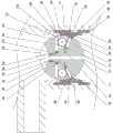
图1是本发明的一种结构示意图;Fig. 1 is a kind of structural representation of the present invention;
图2是本发明的局部放大示意图;Fig. 2 is the partial enlarged schematic diagram of the present invention;
图中:1、储液箱,2、输液直管,3、驱动转轴,4、拉绳,5、活塞球,6、拉绳通孔,7、密封圈,8、进液口,9、出液口,10、定位凸圈,11、球环段,12、倾斜段,13、推动塞,14、安装孔,15、限位塞,16、推动头,17、弹簧安装槽,18、抵接面,19、回位弹簧,20、驱动齿条,21、传动齿轮,22、推动齿条,23、联动弹簧,24、夹块,25、定位凹槽,26、楔块,27、推动面,28、压杆,29、驱动面,30、复位弹簧,31、安装腔,32、封闭块,33、前段管,34、后段管,35、外环缺,36、内环缺,37、定位环,38、后定位环槽,39、前定位环槽,40、连接环,41、导向面,42、避让环槽,43、导轮,44、出液管,45、夹针头。In the picture: 1. Liquid storage tank, 2. Infusion straight pipe, 3. Driving shaft, 4. Pull rope, 5. Piston ball, 6. Through hole for pull rope, 7. Sealing ring, 8. Liquid inlet, 9. Liquid outlet, 10, Positioning convex ring, 11, Ball ring section, 12, Inclined section, 13, Push plug, 14, Mounting hole, 15, Limit plug, 16, Push head, 17, Spring mounting groove, 18, Abutting surface, 19, Return spring, 20, Driving rack, 21, Transmission gear, 22, Pushing rack, 23, Linkage spring, 24, Clamping block, 25, Positioning groove, 26, Wedge block, 27, Pushing surface, 28, pressure rod, 29, driving surface, 30, return spring, 31, installation cavity, 32, closing block, 33, front tube, 34, rear tube, 35, missing outer ring, 36, missing inner ring , 37, positioning ring, 38, rear positioning ring groove, 39, front positioning ring groove, 40, connecting ring, 41, guide surface, 42, avoidance ring groove, 43, guide wheel, 44, liquid outlet pipe, 45, clamp Needle.
具体实施方式Detailed ways
下面通过具体实施例,并结合附图,对本发明的技术方案作进一步的具体描述:Below by specific embodiment, and in conjunction with accompanying drawing, the technical scheme of the present invention is further described in detail:
实施例:一种流动注射分析仪用恒流泵(参见附图1、附图2),包括储液箱1、输液直管2、驱动转轴3、传动拉索、两导轮43,输液直管安装在储液箱内靠近底部位置,输液直管两端开口。驱动转轴和导轮均安装在储液箱内且均置于输液直管上方。传动拉索包括拉绳4、若干活塞球5,活塞球上设有拉绳通孔6,拉绳贯穿拉绳通孔将活塞球串联在一起,拉绳通孔内靠近两端位置均安装有密封圈7。传动拉索首尾相接,传动拉索贯穿输液直管且绕过两导轮后缠绕在驱动转轴上,驱动转轴安装在两导轮之间靠上位置,驱动转轴传动连接驱动电机,活塞球与输液直管相适配,驱动转轴转动带动活塞球在输液直管内向前移动。输液直管一端为进液口8,活塞球从进液口进入输液直管中,进液口呈喇叭口状结构。Example: A constant flow pump for a flow injection analyzer (see Figure 1 and Figure 2 ), comprising a liquid storage tank 1, a straight infusion tube 2, a drive shaft 3, a transmission cable, and two guide wheels 43, the infusion straight The tube is installed in the liquid storage tank near the bottom, and both ends of the straight infusion tube are open. Both the drive shaft and the guide wheel are installed in the liquid storage tank and placed above the infusion straight pipe. The transmission cable includes a cable 4 and a plurality of
输液直管上设有出液口9,出液口上连接出液管44,出液管延伸到储液箱外部。输液直管内壁上出液口前侧安装可变形的定位凸圈10,定位凸圈内壁包括球环段11和倾斜段12,球环段与活塞球适配。活塞球内安装若干推动塞13,推动塞均布设置, 推动塞端部延伸出活塞球前侧表面且可抵接到定位凸圈上,活塞球上和推动塞对应位置设有安装孔14,安装孔开口位置紧固连接限位塞15,推动塞一端设有推动头16,另一端设有弹簧安装槽17,推动头端部设有倾斜设置的抵接面18,推动头贯穿限位塞,推动头端部到活塞球中心的距离小于活塞球的半径。The liquid infusion straight pipe is provided with a liquid outlet 9, and the liquid outlet is connected with a liquid outlet pipe 44, and the liquid outlet pipe extends to the outside of the liquid storage tank. A deformable positioning
推动塞和活塞球之间连接回位弹簧19,回位弹簧安装在弹簧安装槽内,推动塞上设有驱动齿条20,活塞球内安装传动齿轮21和推动齿条22,传动齿轮啮合传动在驱动齿条和推动齿条之间,推动齿条通过联动弹簧23连接夹块24,夹块夹紧在拉绳上,夹块朝向拉绳的表面上设有若干夹针头45。夹块与拉绳夹紧的表面呈内凹弧形结构。A
活塞球后侧表面上设有定位凹槽25,定位凹槽呈球冠状结构。夹块上设有楔块26,楔块上设有倾斜设置的推动面27,定位凹槽底面安装若干和楔块一一对应设置的压杆28,压杆前端设有倾斜设置的驱动面29,驱动面贴合在推动面上,压杆后端向后延伸出定位凹槽底面,压杆和活塞球之间连接复位弹簧30。压杆向后移动可将夹块向拉绳方向推动。活塞球内设有安装腔31,推动齿条、传动齿轮、夹块、推动塞均置于安装腔内,活塞球表面上紧固连接用于封闭安装腔的封闭块32。The rear surface of the piston ball is provided with a
输液直管包括前段管33、后段管34,定位凸圈置于前段管和后段管的连接位置,前段管外壁上与后段管连接位置设有外环缺35,后段管内壁上与前段管连接位置设有内环缺36,前段管外环缺位置与后段管内环缺位置套装连接在一起,后段管内内环缺位置紧固安装定位环37,定位环前端外壁上设有后定位环槽38,前段管外环缺后端外壁上设有前定位环槽39,定位凸圈前后两端均设有连接环40,两连接环分别紧密连接在前定位环槽和后定位环槽内。前侧连接环的前端外壁上以及后侧连接环的后端外壁上均设有倾斜设置的导向面41。定位凸圈外壁上设有避让环槽42。The infusion straight pipe includes a front-section pipe 33 and a rear-section pipe 34. The positioning convex ring is placed at the connection position of the front-section pipe and the rear-section pipe. The outer wall of the front-section pipe is connected with the rear-section pipe. There is an inner ring missing 36 at the connection position with the front pipe, the outer ring missing position of the front pipe is sleeved and connected with the inner ring missing position of the rear pipe, the
工作时,驱动转轴转动带动活塞球在输液直管内向前移动,置于储液箱内的活塞球不断进入输液直管中,活塞球进入输液直管向前移动过程中,输液直管开口位置形成负压将储液箱内的载流液吸入输液直管中,载流液随活塞球一起在输液直管内移动。活塞球到达定位凸圈位置后,向外伸出的推动塞抵接到定位凸圈上,推动塞向内移动,从而通过驱动齿条带动传动齿轮转动,传动齿轮带动推动齿条向远离拉绳方向移动,从而使夹块与拉绳分离,此时拉绳与拉绳通孔之间摩擦力小,随着驱动转轴的继续转动,拉绳继续向前移动,而定位凸圈位置的活塞球保持不动,拉绳在该活塞球内的拉绳通孔内移动,将后方的活塞球继续向前拉动,而出液口靠近定位凸圈后侧,定位凸圈位置的活塞球与其后的一活塞球的间距逐渐减小,载流液被从出液口压出,当后一活塞球的表面贴合到前面活塞球的定位凹槽时,压杆被向前推动,压杆上的驱动面推动楔块上的推动面向靠近拉绳方向移动,从而使夹块夹紧拉绳,拉绳向前移动过程中,随着拉力的不断增大,将贴合在定位凸圈上的活塞球拉离该位置,在回位弹簧作用下,推动塞向外伸出,通过驱动齿条、传动齿轮带动推动齿条向靠近拉绳方向移动,从而使夹块夹紧拉绳,活塞球又随拉绳一起移动。此时后一活塞球又抵接到定位凸圈上,重复上述过程,使载流液源源不断地从出液口排出。相邻两活塞球之间残留的载流液回流到储液箱中。夹针头夹持在拉绳上,对拉绳的夹持更加紧固可靠。这种泵工作时达到了蠕动泵的效果,但是泵管不会受到挤压变形,不易损伤,避免了损伤漏液现象,使用寿命长,输液效果好。When working, the driving shaft rotates to drive the piston ball to move forward in the infusion straight pipe, the piston ball placed in the liquid storage tank continuously enters the infusion straight pipe, and the piston ball enters the infusion straight pipe and moves forward, the opening position of the infusion straight pipe is The negative pressure is formed to suck the carrier liquid in the liquid storage tank into the straight infusion pipe, and the carrier liquid moves with the piston ball in the straight infusion pipe. After the piston ball reaches the position of the positioning convex ring, the push plug that protrudes outward abuts on the positioning convex ring, and pushes the plug to move inward, thereby driving the transmission gear to rotate through the driving rack, and the transmission gear drives the pushing rack to move away from the pull rope. moving in the direction, so that the clamping block and the rope are separated. At this time, the friction between the rope and the through hole of the rope is small. As the driving shaft continues to rotate, the rope continues to move forward, and the piston ball at the position of the convex ring is positioned. Keep still, the pull rope moves in the through hole of the pull rope in the piston ball, and the rear piston ball continues to be pulled forward, and the liquid outlet is close to the rear side of the positioning convex ring. The spacing of a piston ball gradually decreases, and the carrier liquid is pressed out from the liquid outlet. When the surface of the latter piston ball is fitted to the positioning groove of the front piston ball, the pressure rod is pushed forward, and the pressure rod on the pressure rod is pushed forward. The driving surface pushes the pushing surface on the wedge block to move towards the direction of the pull rope, so that the clamp block clamps the pull rope. During the forward movement of the pull rope, with the continuous increase of the pulling force, the piston that fits on the positioning convex ring will be moved. The ball is pulled away from this position, and under the action of the return spring, the push plug extends outward, and the drive rack and transmission gear drive the push rack to move toward the direction of the pull rope, so that the clamp block clamps the pull rope, and the piston ball moves again. Move with the drawstring. At this time, the next piston ball abuts on the positioning convex ring again, and the above process is repeated, so that the carrier liquid is continuously discharged from the liquid outlet. The residual carrier liquid between two adjacent piston balls is returned to the liquid storage tank. The clamping needle is clamped on the pull rope, and the clamping of the pull rope is more firm and reliable. The pump achieves the effect of a peristaltic pump when working, but the pump tube will not be squeezed and deformed, is not easily damaged, avoids damage and leakage, has a long service life, and has a good infusion effect.
以上所述的实施例只是本发明较佳的方案,并非对本发明作任何形式上的限制,在不超出权利要求所记载的技术方案的前提下还有其它的变体及改型。The above-mentioned embodiments are only preferred solutions of the present invention, and do not limit the present invention in any form. There are other variations and modifications under the premise of not exceeding the technical solutions recorded in the claims.
Claims (7)
Priority Applications (1)
| Application Number | Priority Date | Filing Date | Title |
|---|---|---|---|
| CN201910876402.0ACN110763859B (en) | 2019-09-17 | 2019-09-17 | Constant flow pump for flow injection analyzer |
Applications Claiming Priority (1)
| Application Number | Priority Date | Filing Date | Title |
|---|---|---|---|
| CN201910876402.0ACN110763859B (en) | 2019-09-17 | 2019-09-17 | Constant flow pump for flow injection analyzer |
Publications (2)
| Publication Number | Publication Date |
|---|---|
| CN110763859Atrue CN110763859A (en) | 2020-02-07 |
| CN110763859B CN110763859B (en) | 2022-10-21 |
Family
ID=69329927
Family Applications (1)
| Application Number | Title | Priority Date | Filing Date |
|---|---|---|---|
| CN201910876402.0AActiveCN110763859B (en) | 2019-09-17 | 2019-09-17 | Constant flow pump for flow injection analyzer |
Country Status (1)
| Country | Link |
|---|---|
| CN (1) | CN110763859B (en) |
Cited By (1)
| Publication number | Priority date | Publication date | Assignee | Title |
|---|---|---|---|---|
| CN113266548A (en)* | 2021-07-19 | 2021-08-17 | 山东高原油气装备有限公司 | Hydraulic bidirectional slurry pump for preventing blockage in oil exploitation |
Citations (8)
| Publication number | Priority date | Publication date | Assignee | Title |
|---|---|---|---|---|
| US20060058740A1 (en)* | 2000-05-11 | 2006-03-16 | David Cise | Apparatus and method for preventing free flow in an infusion line |
| CN101074924A (en)* | 2007-05-16 | 2007-11-21 | 洪陵成 | Method for fastly analyzing chemical oxygen demand by high-pressure flowing injection |
| CN203249914U (en)* | 2013-06-04 | 2013-10-23 | 杭州浩通仪器仪表有限公司 | Injection pump for water quality mercury online analyzer |
| CN107725343A (en)* | 2017-11-09 | 2018-02-23 | 四川君汇科技有限公司 | Combined peristaltic pump and combined positioning and mounting method |
| CN108730165A (en)* | 2018-06-26 | 2018-11-02 | 杭州摩汀科技有限公司 | A kind of multi-channel peristaltic pump and its control method |
| CN208831210U (en)* | 2018-09-15 | 2019-05-07 | 北京宝德仪器有限公司 | Peristaltic pump |
| CN109798240A (en)* | 2019-03-15 | 2019-05-24 | 重庆金山医疗器械有限公司 | A kind of Wriggling Pump Head |
| CN209173118U (en)* | 2018-11-15 | 2019-07-30 | 珠海市海杰科技有限公司 | A kind of continuous and quantitative formula automated injection device |
- 2019
- 2019-09-17CNCN201910876402.0Apatent/CN110763859B/enactiveActive
Patent Citations (8)
| Publication number | Priority date | Publication date | Assignee | Title |
|---|---|---|---|---|
| US20060058740A1 (en)* | 2000-05-11 | 2006-03-16 | David Cise | Apparatus and method for preventing free flow in an infusion line |
| CN101074924A (en)* | 2007-05-16 | 2007-11-21 | 洪陵成 | Method for fastly analyzing chemical oxygen demand by high-pressure flowing injection |
| CN203249914U (en)* | 2013-06-04 | 2013-10-23 | 杭州浩通仪器仪表有限公司 | Injection pump for water quality mercury online analyzer |
| CN107725343A (en)* | 2017-11-09 | 2018-02-23 | 四川君汇科技有限公司 | Combined peristaltic pump and combined positioning and mounting method |
| CN108730165A (en)* | 2018-06-26 | 2018-11-02 | 杭州摩汀科技有限公司 | A kind of multi-channel peristaltic pump and its control method |
| CN208831210U (en)* | 2018-09-15 | 2019-05-07 | 北京宝德仪器有限公司 | Peristaltic pump |
| CN209173118U (en)* | 2018-11-15 | 2019-07-30 | 珠海市海杰科技有限公司 | A kind of continuous and quantitative formula automated injection device |
| CN109798240A (en)* | 2019-03-15 | 2019-05-24 | 重庆金山医疗器械有限公司 | A kind of Wriggling Pump Head |
Cited By (2)
| Publication number | Priority date | Publication date | Assignee | Title |
|---|---|---|---|---|
| CN113266548A (en)* | 2021-07-19 | 2021-08-17 | 山东高原油气装备有限公司 | Hydraulic bidirectional slurry pump for preventing blockage in oil exploitation |
| CN113266548B (en)* | 2021-07-19 | 2021-10-08 | 山东高原油气装备有限公司 | Hydraulic bidirectional slurry pump for preventing blockage in oil exploitation |
Also Published As
| Publication number | Publication date |
|---|---|
| CN110763859B (en) | 2022-10-21 |
Similar Documents
| Publication | Publication Date | Title |
|---|---|---|
| CN110763859B (en) | Constant flow pump for flow injection analyzer | |
| CN105651461B (en) | The sealed valve-testing machine of formula is stretched in one kind | |
| CN114673863A (en) | Robot and detection method for phased array non-destructive testing inside pipeline | |
| CN115014660A (en) | A detection device for oil and gas pipeline inner wall based on large-capacity optical fiber transmission | |
| CN110780084B (en) | A pump structure for flow injection analyzer | |
| CN114776937B (en) | Phased array detection robot and detection method for interior of pipeline | |
| CN216559591U (en) | Be used for fire hose valve detection device | |
| CN111578155A (en) | A noise-based gas leak detection device | |
| CN115096518A (en) | Copper pipe welding position leakproofness check out test set | |
| CN209539342U (en) | Coiled tubing pump light cable device | |
| CN116660190A (en) | Device and method for measuring and controlling ozone in ambient air | |
| CN219200994U (en) | External sampler of pipeline | |
| CN218326707U (en) | Quick connecting device with automatic leak hunting function | |
| CN218381412U (en) | Nitrogen cylinder release curve detects frock | |
| CN118191522A (en) | GIS equipment ultrasonic wave partial discharge detection device | |
| CN115541800B (en) | Ion chromatograph and inhibitor thereof | |
| CN114858971B (en) | A device for detecting hydrogen sulfide content inside a biogas tank | |
| CN110987096A (en) | Device for detecting water quantity of pipeline by utilizing water quantity to drive air pressure change | |
| CN216955045U (en) | Boiler pressure pipeline detection device | |
| CN115524178A (en) | Continuous sampling device of oil smoke | |
| CN105666100B (en) | One kind envelope pressure test machine | |
| CN112444607B (en) | Intelligent water conservancy deep water quality real-time monitoring device and monitoring method thereof | |
| JPH09145687A (en) | Pipe insertion ultrasonic flaw inspection apparatus | |
| CN211401796U (en) | Automatic quantitative sampling device for petroleum oil drums | |
| CN216768633U (en) | Compressing sealed brass connecting pipe fitting |
Legal Events
| Date | Code | Title | Description |
|---|---|---|---|
| PB01 | Publication | ||
| PB01 | Publication | ||
| SE01 | Entry into force of request for substantive examination | ||
| SE01 | Entry into force of request for substantive examination | ||
| GR01 | Patent grant | ||
| GR01 | Patent grant |