CN110763322A - Combined type calibrating device of electronic hanging scale - Google Patents
Combined type calibrating device of electronic hanging scaleDownload PDFInfo
- Publication number
- CN110763322A CN110763322ACN201910994366.8ACN201910994366ACN110763322ACN 110763322 ACN110763322 ACN 110763322ACN 201910994366 ACN201910994366 ACN 201910994366ACN 110763322 ACN110763322 ACN 110763322A
- Authority
- CN
- China
- Prior art keywords
- weight
- plate
- fixedly connected
- screw rod
- electronic crane
- Prior art date
- Legal status (The legal status is an assumption and is not a legal conclusion. Google has not performed a legal analysis and makes no representation as to the accuracy of the status listed.)
- Granted
Links
- 230000007246mechanismEffects0.000claimsabstractdescription92
- 238000012795verificationMethods0.000claimsabstractdescription66
- 238000012360testing methodMethods0.000claimsabstractdescription63
- 238000011068loading methodMethods0.000claimsabstractdescription42
- 230000003068static effectEffects0.000claimsdescription2
- 239000000758substrateSubstances0.000claimsdescription2
- 238000009434installationMethods0.000abstractdescription8
- 238000007689inspectionMethods0.000abstractdescription2
- 239000003638chemical reducing agentSubstances0.000description7
- 230000008878couplingEffects0.000description6
- 238000010168coupling processMethods0.000description6
- 238000005859coupling reactionMethods0.000description6
- 230000008859changeEffects0.000description5
- 238000010586diagramMethods0.000description5
- 238000000034methodMethods0.000description5
- 238000006073displacement reactionMethods0.000description4
- 230000009471actionEffects0.000description3
- 238000005303weighingMethods0.000description3
- 230000000903blocking effectEffects0.000description2
- 238000006243chemical reactionMethods0.000description2
- 230000008569processEffects0.000description2
- 238000013461designMethods0.000description1
- 238000011161developmentMethods0.000description1
- 230000009977dual effectEffects0.000description1
- 230000005484gravityEffects0.000description1
- 238000011900installation processMethods0.000description1
- 238000005259measurementMethods0.000description1
- 238000005272metallurgyMethods0.000description1
- 238000012986modificationMethods0.000description1
- 230000004048modificationEffects0.000description1
- 238000003908quality control methodMethods0.000description1
- 230000009467reductionEffects0.000description1
Images


Classifications
- G—PHYSICS
- G01—MEASURING; TESTING
- G01G—WEIGHING
- G01G23/00—Auxiliary devices for weighing apparatus
- G01G23/01—Testing or calibrating of weighing apparatus
Landscapes
- Physics & Mathematics (AREA)
- General Physics & Mathematics (AREA)
- Testing Of Devices, Machine Parts, Or Other Structures Thereof (AREA)
- Testing Of Individual Semiconductor Devices (AREA)
Abstract
Translated fromChinese
Description
Translated fromChinese技术领域technical field
本发明涉及计量器具检定技术领域,具体地涉及一种电子吊秤的组合式检定装置。The invention relates to the technical field of measuring instrument verification, in particular to a combined verification device of an electronic hanging scale.
背景技术Background technique
电子吊秤是一种对被称物品处于悬吊状态下,进行在线称重的计量器具。目前全国有大量的电子吊秤广泛应用于交通、航空、能源、冶金等各行业称重,随着工业的发展,电子吊秤的量程正在不断扩大,电子吊秤的准确与否关系到贸易公平、安全防护及产品质量控制。为保证其计量性能的准确度,需要对其进行定期的检定或校准,因此检定装置和检定方法对电子吊秤准确性的判定具有至关重要的作用。Electronic hanging scale is a measuring instrument for online weighing of the item being weighed in a suspended state. At present, a large number of electronic crane scales are widely used in transportation, aviation, energy, metallurgy and other industries for weighing. With the development of the industry, the range of electronic crane scales is constantly expanding. The accuracy of electronic crane scales is related to trade fairness. , safety protection and product quality control. In order to ensure the accuracy of its measurement performance, it needs to be regularly verified or calibrated. Therefore, the verification device and verification method play a vital role in determining the accuracy of the electronic crane scale.
根据资料查询,目前电子吊秤的检定或校准是依据国家计量检定规程JJG 539-2016进行,主要有以下两种形式:According to the data query, the current verification or calibration of electronic crane scales is carried out in accordance with the national metrological verification regulations JJG 539-2016, mainly in the following two forms:
一是在吊秤使用现场,采用标准砝码进行现场检定。采用该方法可满足量小程的检定(如500kg、1t),但对于大量程电子吊秤,如30/50/80/100吨,则根本无法满足检定。主要存在以下问题:1、检定时,标准砝码无足够的空间进行悬挂;2、检定现场的吊装装置的承载能力有限;3、检定现场的安全性差,工作效率低;4、砝码运输量大、成本高;5、无法实现电子吊秤的全量程、全性能检定。One is to use standard weights for on-site verification at the site where the crane scale is used. This method can meet the verification of small range (such as 500kg, 1t), but for large-scale electronic crane scales, such as 30/50/80/100 tons, it cannot meet the verification at all. The main problems are as follows: 1. During the verification, the standard weights do not have enough space to hang; 2. The carrying capacity of the hoisting device at the verification site is limited; 3. The safety of the verification site is poor and the work efficiency is low; 4. The weight transportation volume Large, high cost; 5. It is impossible to realize the full range and full performance verification of the electronic crane scale.
二是采用力标准装置进行检定。采用现有的叠加式或静重式力标准装置进行检定,存在以下问题:1、大量程的电子吊秤安装困难、安全性差。根据调查资料显示,目前厂家生产的大量程的吊秤体积大,自重大,个别厂家生产的100吨称量的电子吊秤其重量约为1吨。因此检定人员很难通过人工或机械的方式将吊秤送至指定位置,安装时存在安全隐患;2、不论是叠加式还是静重式力标准装置在检定大量程电子吊秤时存在试验空间不足,无法满足大量程电子吊秤试验空间的要求;3、采用叠加式标准机检定时无法按规程进行检定,根据JJG 539-2016《数字指示秤》检定电子吊秤要求,因其力值控制范围有限,现有叠加式力标准机无法实现电子吊秤最小称量为10e、20e(e为检定分度值)的检定要求。4、采用静重式力标准机检定,存在检定效率低,无法满足其量程下限、鉴别阈的检定要求,同时静重式力标准机造价高,尤其是量程大,其成本尤其高。The second is to use the force standard device for verification. Using the existing superposition or dead weight force standard device for verification, there are the following problems: 1. The large-scale electronic crane scale is difficult to install and has poor safety. According to the survey data, the large-scale crane scales currently produced by manufacturers are large and self-heavy, and the 100-ton electronic crane scales produced by individual manufacturers weigh about 1 ton. Therefore, it is difficult for the verification personnel to send the crane scale to the designated position manually or mechanically, and there are potential safety hazards during installation; 2. Whether it is a superimposed or dead-weight force standard device, there is insufficient test space when verifying a large-scale electronic crane scale. , can not meet the requirements of the test space of the large-scale electronic crane scale; 3. When the superimposed standard machine is used for verification, the verification cannot be carried out according to the regulations. According to the requirements of JJG 539-2016 "Digital Indicating Scale", the electronic crane scale is verified because of its force value control range. Limited, the existing superimposed force standard machine cannot meet the verification requirements of the electronic crane scale with a minimum weighing of 10e and 20e (e is the verification graduation value). 4. The dead-gravity force standard machine is used for verification, which has low verification efficiency and cannot meet the verification requirements of the lower limit of its range and the identification threshold. At the same time, the dead-gravity force standard machine is expensive, especially with a large range, and its cost is particularly high.
发明内容SUMMARY OF THE INVENTION
本发明要解决的技术问题,在于提供一种电子吊秤的组合式检定装置,通过结合叠加式力标准装置原理及其静重式力标准原理的优势,设计具有叠加结构和静重砝码加载机构的组合式标准装置,实现电子吊秤按规程进行全量程全性能的检定。The technical problem to be solved by the present invention is to provide a combined verification device of an electronic crane scale. By combining the advantages of the principle of the superimposed force standard device and the principle of the dead weight force standard, the design has a superimposed structure and dead weight loading. The combined standard device of the mechanism realizes the full-scale and full-performance verification of the electronic crane scale according to the regulations.
本发明是这样实现的:一种电子吊秤的组合式检定装置,包括机架、移动横梁、叠加机构、电子吊秤自动装卸机构与静重砝码机构,所述机架具有顶部连接板、中间支撑板与底板,所述移动横梁上下滑动连接于所述机架,且位于所述顶部连接板与所述中间支撑板之间;The invention is realized as follows: a combined verification device of an electronic crane scale includes a frame, a moving beam, a stacking mechanism, an automatic loading and unloading mechanism of the electronic crane scale and a dead weight mechanism, and the frame has a top connecting plate, a middle support plate and a bottom plate, the moving beam is slidably connected to the frame up and down, and is located between the top connecting plate and the middle support plate;
所述叠加机构包括测试压板、压头、标准传感器、油缸和叠加拉杆,所述油缸的缸体与所述移动横梁固定连接,所述油缸的活塞上固设有基板,所述基板位于所述移动横梁的上方,所述基板上固设有所述标准传感器,所述压头与所述测试压板固定连接,所述压头抵住所述标准传感器,所述叠加拉杆穿过所述油缸以及所述基板的中心孔且滑动连接,所述叠加拉杆的一端与所述测试压板固定连接;The superposition mechanism includes a test pressure plate, an indenter, a standard sensor, an oil cylinder and a superimposed pull rod. The cylinder body of the oil cylinder is fixedly connected with the moving beam, and a base plate is fixed on the piston of the oil cylinder, and the base plate is located in the Above the moving beam, the standard sensor is fixed on the base plate, the indenter is fixedly connected to the test pressure plate, the indenter is pressed against the standard sensor, and the superimposed pull rod passes through the oil cylinder and the test platen. The center hole of the base plate is slidably connected, and one end of the superimposed pull rod is fixedly connected to the test pressure plate;
所述电子吊秤自动装卸机构包括上拉头、转接头、移动座与悬臂支架,所述悬臂支架与所述移动横梁固定连接,所述移动座与所述悬臂支架滑动连接,所述移动座位于所述移动横梁的下方,所述转接头具有凸部,所述转接头与所述移动座上下滑动连接,所述凸部能卡住所述移动座,所述转接头还与所述上拉头固定连接,所述转接头开设有型槽,所述叠加拉杆的另一端与所述型槽配合连接;The automatic loading and unloading mechanism of the electronic crane scale includes an upper slider, an adapter, a movable seat and a cantilever bracket, the cantilever bracket is fixedly connected with the movable beam, the movable seat is slidably connected with the cantilever bracket, and the movable seat Located below the moving beam, the adapter has a convex part, the adapter is connected with the moving seat up and down slidingly, the convex part can clamp the moving seat, and the adapter is also connected with the upper part. The pull head is fixedly connected, the adapter is provided with a profile groove, and the other end of the superimposed pull rod is matched and connected with the profile groove;
所述静重砝码机构包括下拉头、球头拉杆、球头座、砝码连接件与砝码组件,所述下拉头位于所述中间支撑板的上方,所述中间支撑板固设有所述球头座,所述球头拉杆穿过所述球头座且滑动连接,所述球头拉杆的一端与所述下拉头固定连接,所述球头拉杆的另一端与所述砝码连接件的一端固定连接,所述砝码连接件的另一端与所述砝码组件拆装式连接。The static weight mechanism includes a pull-down head, a ball-head pull rod, a ball-head seat, a weight connector and a weight assembly, the pull-down head is located above the middle support plate, and the middle support plate is fixed with a The ball head seat, the ball head pull rod passes through the ball head seat and is slidably connected, one end of the ball head pull rod is fixedly connected with the pull-down head, and the other end of the ball head pull rod is connected with the weight One end of the piece is fixedly connected, and the other end of the weight connecting piece is detachably connected with the weight assembly.
进一步地,还包括横梁驱动机构,所述横梁驱动机构包括第一丝杆与第一伺服电机,所述第一丝杆的顶端与所述顶部连接板转动连接,所述第一丝杆的底端与所述中间支撑板转动连接,所述第一丝杆还与所述移动横梁螺纹连接,所述第一伺服电机的机身与所述顶部连接板固定连接,所述第一伺服电机的输出轴与所述第一丝杆的顶端传动连接。Further, it also includes a beam drive mechanism, the beam drive mechanism includes a first screw rod and a first servo motor, the top of the first screw rod is rotatably connected to the top connecting plate, and the bottom of the first screw rod is rotatably connected. The end is rotatably connected with the middle support plate, the first screw rod is also threadedly connected with the moving beam, the body of the first servo motor is fixedly connected with the top connecting plate, the first servo motor The output shaft is in driving connection with the top end of the first screw rod.
进一步地,所述横梁驱动机构还包括导向柱,所述导向柱固设于所述顶部连接板与所述中间支撑板之间,所述移动横梁与所述导向柱滑动连接。Further, the beam driving mechanism further includes a guide column, the guide column is fixed between the top connecting plate and the middle support plate, and the moving beam is slidably connected to the guide column.
进一步地,所述叠加机构还包括均力板,所述标准传感器有复数个且沿着所述基板的圆周方向固定设置,所述压头与所述标准传感器的数量对应,每个所述压头都与所述均力板固定连接。Further, the stacking mechanism further includes a force equalization plate, the standard sensors are plural and are fixedly arranged along the circumferential direction of the substrate, the indenters correspond to the number of the standard sensors, and each of the indenters corresponds to the number of the standard sensors. The heads are all fixedly connected with the force equalizing plate.
进一步地,所述电子吊秤自动装卸机构还包括第二丝杆、第二伺服电机与轴承座,所述轴承座有两个且分别固设于所述悬臂支架的两端,所述第二丝杆的两端分别于所述轴承座转动连接,所述第二丝杆穿过所述移动座且螺纹连接,所述第二伺服电机的机身与其中一个轴承座固定连接,所述第二伺服电机的输出轴与所述第二丝杆传动连接。Further, the automatic loading and unloading mechanism of the electronic crane scale also includes a second screw rod, a second servo motor and a bearing seat, and the bearing seat has two and is respectively fixed on both ends of the cantilever bracket, the second Two ends of the screw rod are respectively connected in rotation with the bearing seat, the second screw rod passes through the moving seat and is threadedly connected, the body of the second servo motor is fixedly connected with one of the bearing seats, and the first screw rod is connected to one of the bearing seats. The output shafts of the two servo motors are connected to the second screw rod in a driving manner.
进一步地,所述电子吊秤自动装卸机构还包括第一直线导轨与第二直线滑块,所述第一直线导轨与所述悬臂支架固定连接,所述第一直线滑块与所述移动座固定连接,所述第一直线滑块与所述第一直线导轨滑动连接。Further, the automatic loading and unloading mechanism of the electronic crane scale further comprises a first linear guide rail and a second linear sliding block, the first linear guide rail is fixedly connected with the cantilever bracket, and the first linear sliding block is connected with the The moving base is fixedly connected, and the first linear slider is slidably connected to the first linear guide rail.
进一步地,还包括砝码升降驱动机构,所述砝码升降驱动机构包括砝码升降板、第三丝杆与第三伺服电机,所述第三丝杆的顶端与所述中间支撑板转动连接,所述第三丝杆的底端与所述底板转动连接,所述第三丝杆还与所述砝码升降板螺纹连接,所述第三伺服电机的机身与所述底板固定连接,所述第三伺服电机的输出轴与所述第三丝杆的底端传动连接;Further, it also includes a weight lifting and lowering driving mechanism, the weight lifting driving mechanism includes a weight lifting plate, a third screw rod and a third servo motor, and the top end of the third screw rod is rotatably connected to the intermediate support plate , the bottom end of the third screw rod is rotatably connected with the bottom plate, the third screw rod is also threadedly connected with the weight lifting plate, and the body of the third servo motor is fixedly connected with the bottom plate, The output shaft of the third servo motor is in driving connection with the bottom end of the third screw rod;
所述砝码组件包括砝码连接座、砝码连接套、砝码连接轴、开设有内孔的砝码体,所述砝码体有复数个,处于顶部的砝码体与砝码连接座固定连接,所述砝码连接座卡接于所述砝码连接件的下端,在上下相邻两个砝码体之间设置有所述砝码连接轴与砝码连接套,所述砝码连接轴的上端嵌入所述上方的砝码体的内孔内,所述砝码连接轴的下端与所述砝码连接套通过螺纹固定连接,所述砝码连接套还与下方的所述砝码体的内孔固定连接,处于底部的砝码体放置于所述砝码升降板的上表面。The weight assembly includes a weight connection seat, a weight connection sleeve, a weight connection shaft, and a weight body with an inner hole. There are plural weight bodies, and the weight body at the top and the weight connection seat Fixed connection, the weight connection seat is clamped to the lower end of the weight connection piece, the weight connection shaft and the weight connection sleeve are arranged between the upper and lower adjacent weight bodies, and the weight The upper end of the connecting shaft is embedded in the inner hole of the upper weight body, the lower end of the weight connecting shaft and the weight connecting sleeve are fixedly connected by threads, and the weight connecting sleeve is also connected with the lower weight. The inner hole of the weight body is fixedly connected, and the weight body at the bottom is placed on the upper surface of the weight lifting plate.
进一步地,还包括砝码输送机构,所述砝码输送机构包括砝码移动板、第二直线导轨、第二直线滑块与导轨支撑柱,所述第二直线导轨固定连接于所述砝码升降板的上表面,所述第二直线导轨还与所述导轨支撑柱固定连接,所述第二直线滑块固定连接于所述砝码移动板的下表面,所述第二直线滑块滑动连接于所述第二直线导轨,处于底部的砝码体放置于所述砝码移动板的上表面。Further, it also includes a weight conveying mechanism, the weight conveying mechanism includes a weight moving plate, a second linear guide rail, a second linear sliding block and a guide rail support column, and the second linear guide rail is fixedly connected to the weight The upper surface of the lifting plate, the second linear guide rail is also fixedly connected to the guide rail support column, the second linear slider is fixedly connected to the lower surface of the weight moving plate, and the second linear slider slides Connected to the second linear guide rail, the weight body at the bottom is placed on the upper surface of the weight moving plate.
进一步地,所述砝码输送机构还包括砝码定位座,所述砝码定位座的底端固定连接于所述砝码移动板,所述砝码定位座的顶端能插入所述处于底部的砝码体的内孔。Further, the weight conveying mechanism further includes a weight positioning seat, the bottom end of the weight positioning seat is fixedly connected to the weight moving plate, and the top end of the weight positioning seat can be inserted into the bottom of the weight positioning seat. The inner hole of the weight body.
进一步地,还包括鉴别阈测试机构,所述鉴别阈测试机构包括导向架、第四丝杆、测试移动梁与力传感器,所述导向架固定连接于所述中间支撑板的下表面,所述测试移动梁上下滑动连接于所述导向架,所述第四丝杆的两端与所述导向架转动连接,所述第四丝杆还与所述测试移动梁螺纹连接,所述力传感器与所述测试移动梁固定连接,所述砝码连接件穿过所述力传感器且滑动连接,所述砝码连接件具有挡环,所述挡环位于所述力传感器的下方。Further, it also includes an identification threshold testing mechanism, the identification threshold testing mechanism includes a guide frame, a fourth screw rod, a test moving beam and a force sensor, the guide frame is fixedly connected to the lower surface of the intermediate support plate, and the The test moving beam is slidably connected to the guide frame up and down, two ends of the fourth screw rod are rotatably connected to the guide frame, the fourth screw rod is also threadedly connected to the test moving beam, and the force sensor is connected to the guide frame. The test moving beam is fixedly connected, the weight connecting piece passes through the force sensor and is slidably connected, and the weight connecting piece has a blocking ring, and the blocking ring is located below the force sensor.
本发明具有如下优点:1、研制的电子吊秤的组合式检定装置,能够实现电子吊秤真正意义上按规程JJG 539-2016《数字指示秤》进行全量程全性能的检定,解决了现有砝码检定大量程电子吊秤检不了、检不准的重大难题,检定装置智能化程度高、效率高、安全性强;The invention has the following advantages: 1. The developed combined verification device of the electronic crane scale can realize the full-scale and full-performance verification of the electronic crane scale in a true sense according to the regulation JJG 539-2016 "Digital Indicating Scale", which solves the problem of existing The major problem of undetectable and inaccurate inspection of large-scale electronic crane scales in weight verification is that the verification device has a high degree of intelligence, high efficiency and strong safety;
2、本装置结合了叠加结构和静重结构的双重优势,即叠加结构具有加载速度快、稳定性好、量程上限高、成本造价低的优势,而静重结构准确度高、力值加卸载稳定、可解决电子吊秤量程下限检不了的难题。2. This device combines the dual advantages of superimposed structure and deadweight structure, that is, the superimposed structure has the advantages of fast loading speed, good stability, high range upper limit, and low cost, while the deadweight structure has high accuracy and can be loaded and unloaded by force. It is stable and can solve the problem that the lower limit of the electronic crane scale cannot be detected.
3、装置设有吊秤自动装卸机构,可解决吊秤安装时人工安装的安全性差、工作强度大等问题,实现全自动安装、自动定位;3. The device is equipped with a crane scale automatic loading and unloading mechanism, which can solve the problems of poor safety and high work intensity of manual installation during crane scale installation, and realize automatic installation and automatic positioning;
4、装置设有鉴别阈测试机构,可以满足鉴别阈测试的要求,解决人工添加小砝码时工作量大、误差率高的问题。4. The device is equipped with an identification threshold testing mechanism, which can meet the requirements of the identification threshold test and solve the problems of large workload and high error rate when adding small weights manually.
附图说明Description of drawings
下面参照附图结合实施例对本发明作进一步的说明。The present invention will be further described below with reference to the accompanying drawings and embodiments.
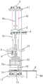
图1为本发明的电子吊秤的组合式检定装置的结构示意立体图。FIG. 1 is a schematic perspective view of the structure of the combined verification device of the electronic crane scale of the present invention.
图2为本发明的电子吊秤的组合式检定装置的结构示意平面图。FIG. 2 is a schematic plan view of the structure of the combined verification device of the electronic crane scale of the present invention.
图3为图2中A的局部放大示意图。FIG. 3 is a partial enlarged schematic diagram of A in FIG. 2 .
图4为本发明中移动横梁、叠加机构以及电子吊秤自动装卸机构的位置关系示意立体图。4 is a schematic perspective view of the positional relationship of the moving beam, the stacking mechanism and the automatic loading and unloading mechanism of the electronic crane scale in the present invention.
图5为本发明中叠加拉杆、移动座以及转接头的装配示意图。FIG. 5 is a schematic view of the assembly of the superimposed pull rod, the movable seat and the adapter in the present invention.
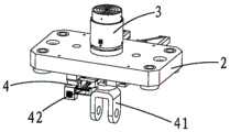
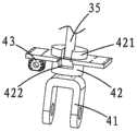
图6为本发明中电子吊秤自动装卸机构的结构示意主视图。6 is a schematic front view of the structure of the automatic loading and unloading mechanism of the electronic crane scale in the present invention.
图6a为图6的右视图。FIG. 6a is a right side view of FIG. 6 .
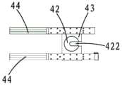
图6b为图6的俯视图。FIG. 6b is a top view of FIG. 6 .
图7为本发明中移动横梁、叠加机构以及电子吊秤自动装卸机构的装配示意平面图。7 is a schematic plan view of the assembly of the moving beam, the stacking mechanism and the automatic loading and unloading mechanism of the electronic crane scale in the present invention.
图7a为图7的B-B向剖视示意图。FIG. 7a is a schematic cross-sectional view taken along the line B-B of FIG. 7 .
图8为本发明中油缸、标准传感器、压头以及均力板的装配示意图。FIG. 8 is a schematic diagram of the assembly of the oil cylinder, the standard sensor, the pressure head and the force equalizing plate in the present invention.
图9为本发明中砝码组件的加载状态示意图。FIG. 9 is a schematic diagram of the loading state of the weight assembly in the present invention.
图9a为图9的C-C向剖视示意图。FIG. 9a is a schematic cross-sectional view taken along the line C-C of FIG. 9 .
图10为本发明中砝码组件的卸载状态示意图。FIG. 10 is a schematic diagram of the unloading state of the weight assembly in the present invention.
图10a为图10的D-D向剖视示意图。FIG. 10a is a schematic cross-sectional view taken along the line D-D of FIG. 10 .
图11为本发明中下拉头、球头拉杆、中间支撑板以及砝码连接件的装配示意图。FIG. 11 is a schematic diagram of the assembly of the pull-down head, the ball-head pull rod, the middle support plate and the weight connecting piece in the present invention.
图12为本发明中砝码输送机构的结构示意立体图。12 is a schematic perspective view of the structure of the weight conveying mechanism in the present invention.
图13为本发明中砝码输送机构的结构示意平面图。13 is a schematic plan view of the structure of the weight conveying mechanism in the present invention.
图中标记:机架1,顶部连接板11,中间支撑板12,底板13,上立柱14,下立柱15,移动横梁2,叠加机构3,测试压板31,压头32,标准传感器33,油缸34,活塞341,叠加拉杆35,基板36,均力板37,电子吊秤自动装卸机构4,上拉头41,转接头42,凸部421,型槽422,移动座43,悬臂支架44,第二丝杆45,第二伺服电机46,轴承座47,第一直线导轨48,第二直线滑块49,静重砝码机构5,下拉头51,球头拉杆52,球头座53,砝码连接件54,挡环541,砝码组件55,砝码连接座551,砝码连接套552,砝码连接轴553,砝码体554,内孔5541,横梁驱动机构6,第一丝杆61,第一伺服电机62,梅花联轴器63,换向器64,减速器65,导向柱66,砝码升降驱动机构7,砝码升降板71,第三丝杆72,第三伺服电机73,砝码输送机构8,砝码移动板81,把手811,第二直线导轨82,第二直线滑块83,导轨支撑住84,砝码定位座85,鉴别阈测试机构9,导向架91,导杆911,第四丝杆92,测试移动梁93,力传感器94。Labels in the figure: frame 1, top connecting plate 11, middle support plate 12, bottom plate 13, upper column 14, lower column 15, moving beam 2, stacking mechanism 3, test pressure plate 31, indenter 32, standard sensor 33, oil cylinder 34, piston 341, superimposed pull rod 35, base plate 36, equalizing plate 37, automatic loading and unloading mechanism of electronic crane scale 4, upper slider 41, adapter 42, convex part 421, groove 422, movable seat 43, cantilever bracket 44, The second screw rod 45, the second servo motor 46, the bearing seat 47, the first linear guide rail 48, the second linear slider 49, the dead weight mechanism 5, the pull-down head 51, the ball head tie rod 52, the ball head seat 53 , weight connecting piece 54, retaining ring 541, weight assembly 55, weight connecting seat 551, weight connecting sleeve 552, weight connecting shaft 553, weight body 554, inner hole 5541, beam drive mechanism 6, first The screw 61, the first servo motor 62, the plum coupling 63, the commutator 64, the reducer 65, the guide column 66, the weight lifting drive mechanism 7, the weight lifting plate 71, the third screw 72, the third Servo motor 73, weight conveying mechanism 8, weight moving plate 81, handle 811, second linear guide 82, second linear slider 83, guide rail support 84, weight positioning seat 85, discrimination threshold testing mechanism 9, guide Rack 91 , guide rod 911 , fourth screw rod 92 , test moving beam 93 , force sensor 94 .
具体实施方式Detailed ways
参阅图1至图13,本发明的电子吊秤的组合式检定装置的优选实施例;包括机架1、移动横梁2、叠加机构3、电子吊秤自动装卸机构4与静重砝码机构5,还包括横梁驱动机构6、砝码升降驱动机构7、砝码输送机构8与鉴别阈测试机构9;所述机架1具有顶部连接板11、中间支撑板12与底板13,所述移动横梁2上下滑动连接于所述机架1,且位于所述顶部连接板11与所述中间支撑板12之间;机架1还具有复数个上立柱14与下立柱15,上立柱14的两端分别与顶部连接板11以及中间支撑板12通过螺母锁紧连接,下立柱15的两端分别与中间支撑板12以及底板13通过螺母锁紧固定连接。1 to 13, the preferred embodiment of the combined verification device of the electronic crane scale of the present invention includes a
所述横梁驱动机构6包括第一丝杆61与第一伺服电机62,所述第一丝杆61的顶端与所述顶部连接板11转动连接,所述第一丝杆61的底端与所述中间支撑板12转动连接,第一丝杆61的两端与设置的轴承配合进行转动;所述第一丝杆61还与所述移动横梁2螺纹连接,从而当第一丝杆61正转或反转时,移动横梁2就能上下移动;所述第一伺服电机62的机身与所述顶部连接板11固定连接,所述第一伺服电机62的输出轴与所述第一丝杆61的顶端传动连接。更具体地横梁驱动机构6还包括梅花联轴器63、换向器64与减速器65,第一伺服电机62的输出轴通过梅花联轴器63与换向器64连接,换向器64根据第一伺服电机62的转向分别转换成输出所需要的转动方向,从而带动与换向器64相连接的减速器65,减速器65通过一定的减速比,将第一伺服电机62的转速转化为所需要的特定的转速,从而驱动与之相连的第一丝杆61,进而使丝杆进行转动。所述横梁驱动机构6还包括导向柱66,所述导向柱66固设于所述顶部连接板11与所述中间支撑板12之间,所述移动横梁2与所述导向柱66滑动连接。导向柱66使移动横梁2上下滑动稳定。导向柱66与第一丝杆61的位置请再参阅图1与图2。The
请再参阅图4、图5、图7至图8,所述叠加机构3包括测试压板31、压头32、标准传感器33、油缸34和叠加拉杆35,所述油缸34的缸体与所述移动横梁2固定连接,所述油缸34的活塞341上固设有基板36,所述基板36位于所述移动横梁2的上方,所述基板36上固设有所述标准传感器33,所述压头32与所述测试压板31固定连接,所述压头32抵住所述标准传感器33,所述叠加拉杆35穿过所述油缸34以及所述基板36的中心孔且滑动连接,所述叠加拉杆35的一端与所述测试压板31固定连接;叠加机构3用于在电子吊秤检定时提供叠加力源的装置。在检定工作时,油缸34的活塞341向上移动,从而带动基板36上的标准传感器33、压头32以及测试压板31向上移动,此时标准传感器33对压头32施加向上作用力,压头32与标准传感器33通过中心孔定位设置,叠加拉杆35的另一端向上拉动转接头42,与转接头42连接的上拉头41安装有电子吊秤,标准传感器33上就能检测到油缸34施加的作用力数值,而电子吊秤上同样显示有作用力数值,通过比对这两个作用力数值对该电子吊秤进行检定。Please refer to FIGS. 4 , 5 , 7 to 8 again, the
所述叠加机构3还包括均力板37,所述标准传感器33有复数个且沿着所述基板36的圆周方向固定设置,所述压头32与所述标准传感器33的数量对应,每个所述压头32都与所述均力板37固定连接。这样就油缸34施加的作用力更均匀地传递给各个压头32以及测试压板31,结合各个标准传感器33的测量到的作用力数值,更精准地对电子吊秤进行检定。The stacking
请再参阅图6至图7a,所述电子吊秤自动装卸机构4包括上拉头41、转接头42、移动座43与悬臂支架44,还包括第二丝杆45、第二伺服电机46与轴承座47以及第一直线导轨48与第一直线滑块49;所述悬臂支架44与所述移动横梁2固定连接,所述第一直线导轨48与所述悬臂支架44固定连接,所述第一直线滑块49与所述移动座43固定连接,所述第一直线滑块49与所述第一直线导轨48滑动连接;所述移动座43位于所述移动横梁2的下方,所述转接头42具有凸部421,所述转接头42与所述移动座43上下滑动连接,所述凸部421能卡住所述移动座43,所述转接头42还与所述上拉头41固定连接,所述转接头42开设有型槽422,所述叠加拉杆35的另一端与所述型槽422配合连接;具体地型槽422为倒“T”型槽422,叠加拉杆35的另一端卡入该倒“T”型槽422内,当叠加拉杆35向上移动时能提起转接头42,从而对与转接头42连接的上拉头41安装的电子吊秤施加向上的作用力;当叠加拉杆35不工作时,转接头42的凸部421卡住移动座43,避免转接头42脱离移动座43。所述轴承座47有两个且分别固设于所述悬臂支架44的两端,所述第二丝杆45的两端分别于所述轴承座47转动连接,所述第二丝杆45穿过所述移动座43且螺纹连接,所述第二伺服电机46的机身与其中一个轴承座47固定连接,所述第二伺服电机46的输出轴与所述第二丝杆45传动连接。第二伺服电机46使第二丝杆45正转或反转,从而使移动座43前后移动;在需要更换检定的电子吊秤时,移动座43在第二伺服电机46的驱动下向外移动,转接头42的倒“T”型槽422与叠加拉杆35的另一端脱离,在移动座43向外移动至指定位置时,工作人员就更换位于上拉头41的电子吊秤,电子吊秤的上端与上拉头41通过插销固定。Please refer to FIG. 6 to FIG. 7a again, the electronic crane scale automatic loading and
电子吊秤自动装卸机构4的设置是用于安装和拆卸被检的电子吊秤;当需要进行安装电子吊秤时,第一伺服驱动第一丝杆61转动,带动移动横梁2向下运动到所需要的位置,第二伺服电机46驱动第二丝杆45转动,第二丝杆45通过滚珠丝杆螺母配合带动移动座43及第一直线滑块49在第一直线导轨48上向外移动,转接头42和上拉头41一起随着移动座43向外移动,当移动到电子吊秤的吊钩所能扣上的位置停止。当电子吊秤的上钩部分与上拉头41通过插销固定后,移动横梁2往上运动,运动至电子吊秤的下钩部分可以与下拉头51进行配合时,停止移动横梁2的运动;同时第二伺服电机46将驱动第二丝杆45,带动移动座43和上拉头41及上拉头41的电子吊秤往机架1中心移动,在机架1的中心位置设有定位装置,当移动座43移动到定位装置时,停止运动,此时上拉头41处于机架1的中心位置。此时再微调节移动横梁2的上下运动,让电子吊秤的下钩部分与下拉头51完全配合接触上,插上插销,此时即完成电子吊秤的安装。电子吊秤检定完成后,需要将电子吊秤从机架1上卸除下来,其操作方案与装载时相反即可。The setting of the electronic crane scale automatic loading and
请再参阅图9至图11,所述静重砝码机构5包括下拉头51、球头拉杆52、球头座53、砝码连接件54与砝码组件55,所述下拉头51位于所述中间支撑板12的上方,所述中间支撑板12固设有所述球头座53,所述球头拉杆52穿过所述球头座53且滑动连接,所述球头拉杆52的一端与所述下拉头51固定连接,所述球头拉杆52的另一端与所述砝码连接件54的一端固定连接,所述砝码连接件54的另一端与所述砝码组件55拆装式连接。在进行检定工作时,往砝码连接件54的另一端添加所需的砝码,砝码连接件54就有所添加的向下作用力,从而球头拉杆52以及下拉头51就有该向下作用力,下拉头51安装有电子吊秤,电子吊秤显示有作用力数值,工作人员通过计算所添加的砝码标识的重量进行比对,这样就对电子吊秤进行静重式检定。Please refer to FIG. 9 to FIG. 11 again, the
所述砝码升降驱动机构7包括砝码升降板71、第三丝杆72与第三伺服电机73,所述第三丝杆72的顶端与所述中间支撑板12转动连接,所述第三丝杆72的底端与所述底板13转动连接,所述第三丝杆72还与所述砝码升降板71螺纹连接,当第三丝杆72进行正转或反转时,砝码升降板71就进行升降移动;所述第三伺服电机73的机身与所述底板13固定连接,所述第三伺服电机73的输出轴与所述第三丝杆72的底端传动连接;参考上述段落内容,第三伺服电机73与第三丝杆72之间同样设置有梅花联轴器、换向器与减速器。The weight lifting and lowering
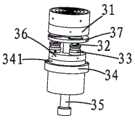
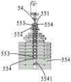
再参阅图9至图10a,所述砝码组件55包括砝码连接座551、砝码连接套552、砝码连接轴553、开设有内孔5541的砝码体554,所述砝码体554有复数个,处于顶部的砝码体554与砝码连接座551固定连接,所述砝码连接座551卡接于所述砝码连接件54的下端,在上下相邻两个砝码体554之间设置有所述砝码连接轴553与砝码连接套552,所述砝码连接轴553的上端嵌入所述上方的砝码的内孔5541内,所述砝码连接轴553的下端与所述砝码连接套552通过螺纹固定连接,所述砝码连接套552还与下方的所述砝码的内孔5541固定连接;处于底部的砝码体554放置于所述砝码移动板81的上表面,砝码移动板81放置于砝码升降板71上。根据实际情况,砝码体554有多种的重量规格,每种的重量规格的砝码体554有若干个。9 to 10a, the
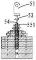
砝码与砝码之间的连接是采用逐级套接的方式进行。砝码组件55装配具体如下,砝码连接套552通过若干个螺栓固定安装在最底端的第n个砝码体554的内孔5541上,而后放上第n-1个砝码体554,将砝码连接轴553穿过第n-1个砝码体的内孔5541与砝码连接套552采用螺纹连接方式配合安装,装好后,安装第n-1个砝码体554上的砝码连接套552,以此类推,自下而上的对砝码体554进行安装,直至安装好顶端的第1个砝码体554,最后将砝码连接座551和砝码连接件54进行安装。当加载的时候,如图所示,砝码升降机构驱动砝码升降板71向下运动,砝码升降板71带动砝码整体向下运动,运动直至砝码连接件54与砝码连接座551接触上,此时砝码连接件54将砝码连接座551及其第1块砝码体554一起拉起,即实现第1块砝码体554的加载,当需要进行第2块砝码体554的加载时,继续给砝码升降驱动机构7发送指令,使得砝码升降驱动机构7继续驱动砝码升降板71向下运动,直至第2块砝码体554连接的砝码连接轴553的上端与砝码体554的内孔5541接触上,即实现第2块砝码的加载,以此类推,直至把所有砝码体554加载上。当卸载时,砝码升降驱动机构7驱动砝码升降板71向上运动,直至底端第n个砝码体554的上表面与第n-1个砝码体554的下表面贴合,此时砝码连接轴553的上端与第n-1个砝码体554脱离,即实现第n个砝码体554的卸载,以次类推砝码升降板71继续向上运动,直至顶端第1个砝码体554的砝码连接座551脱离接触砝码连接件54的下端,即完成所有砝码的卸载。The connection between the weights is carried out in a step-by-step manner. The assembly of the
请再参阅图12至图13,所述砝码输送机构8包括砝码移动板81、第二直线导轨82、第二直线滑块83与导轨支撑柱,所述第二直线导轨82固定连接于所述砝码升降板71的上表面,所述第二直线导轨82还与所述导轨支撑柱固定连接,所述第二直线滑块83固定连接于所述砝码移动板81的下表面,所述第二直线滑块83滑动连接于所述第二直线导轨82,处于底部的砝码体554放置于所述砝码移动板81的上表面。在需要移出砝码组件55时,拆除砝码连接座551与顶部砝码体554的连接,将砝码升降板71向下移动至原位,然后砝码移动板81由砝码升降板71位置移动至导轨支撑柱位置。其中砝码移动板81上固设有把手811,便于工作人员对砝码移动板81进行移动。所述砝码输送机构8还包括砝码定位座85,所述砝码定位座85的底端固定连接于所述砝码移动板81,所述砝码定位座85的顶端能插入所述处于底部的砝码体554的内孔5541;砝码定位座85呈锥形。Please refer to FIG. 12 to FIG. 13 again, the
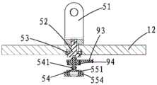
请再参阅图3与图11,所述鉴别阈测试机构9包括导向架91、第四丝杆92、测试移动梁93与力传感器94,所述导向架91固定连接于所述中间支撑板12的下表面,所述测试移动梁93上下滑动连接于所述导向架91,其中导向架91具有导杆911,测试移动梁93与导杆911滑动连接;所述第四丝杆92的两端与所述导向架91转动连接,所述第四丝杆92还与所述测试移动梁93螺纹连接,当第四丝杆92进行正转或反转时,测试移动梁93就能上下移动;所述力传感器94与所述测试移动梁93固定连接,所述砝码连接件54穿过所述力传感器94且滑动连接,所述砝码连接件54具有挡环541,所述挡环541位于所述力传感器94的下方。力传感器94可采用小量程,满足鉴别阈明细表中的加载要求。进行电子吊秤鉴别阈测试时,测试移动梁93向下移动,从而力传感器94对挡环541产生向下的作用力,力传感器94显示该作用力的数值,该向下的作用力施加在砝码连接件54,进而施加在球头拉杆52、下拉头51以及电子吊秤。根据实际需要,通过调节测试移动梁93的移动量,从而控制对砝码连接件54施加的作用力大小,力传感器94显示施加的作用力数值变化,同时工作人员观察电子吊秤的显示数值是否有变化及变化量。Please refer to FIG. 3 and FIG. 11 again, the identification
鉴别阈测试机构9的作用是对电子吊秤检定时进行的鉴别阈测试时所需的加载结构。根据国家计量检定规程JJG 539-2016《数字指示秤》的要求,电子吊秤进行检定时,需对其鉴别阈进行测试,测试过程按照如下方式进行:“在处于平衡状态的秤上,轻缓地放上或取下一个等于实际分度值1.4倍(1.4e)的附加载荷,此时秤的示值应发生明显地改变。”根据规程要求,目前检定电子吊秤鉴别阈主要采用手工加载的方式进行,通常是每0.1e进行加载,即根据不同分度值准备不同重量的小砝码。如下表1所示,不同规格的电子吊秤,对应的分度值是不一样的,需要准备大量的不同规格的小砝码,需要加载时,手动的一块一块(0.1e)的对电子吊秤加载,直至加完1.4e的小砝码。这种加载方式,自动化程度低,工作量大,效率低,人工加载还容易导致误差率高。因此本发明设置的鉴别阈测试机构9,可实现鉴别阈测试的自动加卸载,准确度高,自动化水平高。The function of the identification
加载时:当电子吊秤加载处于平衡状态(即砝码处于加载状态)时,第四伺服电机驱动第四丝杆92转动,使测试移动梁93沿着导杆911向下运动,当测试移动梁93上的力传感器94与砝码连接件54的挡环541接触后产生力值,根据作用力与反作用力原理,此时就对砝码连接件54施加载荷,即对电子吊秤施加载荷,此时通过控制系统控制第四伺服电机的转动量,对力传感器94缓慢的施加0.1e的载荷增加量,直至完成1.4e的加载,此时观察电子吊秤的示值是否有明显的发生改变,即完成鉴别阈的测试。When loading: when the electronic crane scale is loaded in a balanced state (that is, the weight is in a loaded state), the fourth servo motor drives the
表1、鉴别阈加载明细表Table 1. Discriminant Threshold Loading List
本发明的电子吊秤的组合式检定装置具体实现方案:以本发明的量程为50t组合式检定装置检定一台30吨的电子吊秤为例,检定装置含5000kg砝码,砝码从上而下依次是:10kg,10kg,20kg,10kg,50kg,100kg,200kg,100kg,500kg,500kg,500kg,500kg,500kg,1000kg,1000kg,总共砝码为5000kg,因此该电子吊秤在200-5000kg的小量程范围采用砝码进行检定,在(5000-30000)kg的大量程范围采用叠加结构进行检定,电子吊秤的分度值e为10kg,检定点为20e,500e,50%max,2000e,max,即检定点为200kg,5000kg,15000kg,20000kg,30000kg。The specific implementation scheme of the combined verification device of the electronic crane scale of the present invention: taking the combined verification device of the present invention with a range of 50t to verify a 30t electronic crane scale as an example, the verification device contains a 5000kg weight, and the weight is from the top The following order is: 10kg, 10kg, 20kg, 10kg, 50kg, 100kg, 200kg, 100kg, 500kg, 500kg, 500kg, 500kg, 500kg, 1000kg, 1000kg, the total weight is 5000kg, so the electronic crane scale is in the range of 200-5000kg The small scale range is verified by weights, and the large scale range of (5000-30000) kg is verified by a superimposed structure. max, that is, the verification points are 200kg, 5000kg, 15000kg, 20000kg, 30000kg.
当电子吊秤需要检定时,把电子吊秤放置在中间支撑板12上,电子吊秤自动装卸机构4通过第二伺服电机46的驱动,将上拉头41沿着第一直线导轨48移出到指定位置,横梁驱动机构6驱动移动横梁2向下运动,直至上拉头41达到电子吊秤的上吊钩位置,此时将电子吊秤的上吊钩放置在上拉头41内部,并插上插销;然后通过第二伺服电机46的驱动将上拉头41送入至与叠加拉杆35可配合的地方,进而叠加拉杆35的另一端进入转接头42的倒“T”型槽422内。到达指定位置后移动横梁2上升,直至电子吊秤的下拉钩可与本发明的下拉头51进行连接,此时往下拉头51插入插销,即完成电子吊秤的安装。需要对电子吊秤进行拆卸时,与安装过程的操作过程相反即可。完成电子吊秤的安装后,开始进行检定。When the electronic crane scale needs to be checked, the electronic crane scale is placed on the
检定时,5000kg以内量程采用砝码加载。第一伺服电机62通过联轴器63、换向器64以及减速器65同步驱动四根第一丝杆61,第一丝杆61带动移动横梁2向上移动,直到被测的电子吊秤产生示值,安装于中间连接板上的位移传感器开始输出位移信号,当位移信号达到目标值时,此时吊挂部分与电子吊秤的下拉钩结合,与第一级砝码分离,移动横梁2停止,完成由吊挂部分重力作用下的下拉头51和砝码连接件54的载荷,此时将电子吊秤进行清零操作。During verification, the range within 5000kg is loaded with weights. The
接着,砝码升降驱动机构7开始工作,第三伺服电机73通过联轴器、转向器以及减速器同步驱动四根第三丝杆72旋转,带动砝码升降板71向下移动,以砝码升降板71的位移信号进行伺服闭环控制系统,在目标砝码未加载时以位移信号控制砝码升降板71移动,直至第6块砝码(100kg)加载到位,即完成第一个检定点200kg加载,此时读取电子吊秤的示值,即为第一检定点的示值。第二检定点5000kg,第三伺服电机73继续控制砝码升降板71向下移动,直至完成所有砝码的加载,即位移传感器信息达到目标设定值,此时砝码与砝码移动板81脱离,完成5000kg砝码的加载,读取电子吊秤的示值。Then, the weight lifting and lowering
完成砝码加载后,大量程检定采用叠加结构进行。因油缸34、标准传感器33安装于移动横梁2上,通过叠加拉杆35与上拉头41组成的反力结构可以使标准传感器33的压向力转换成拉向力。叠加系统工作时,伺服液压动力系统控制加载油缸34,通过上拉头41与叠加拉杆35之间的作用力对标准传感器33、被测电子吊秤同时加载,将标准传感器33的力值作为参考力标准,形成闭环控制系统,被测电子吊秤通过上拉头41与标准传感器33组串联,受力大小相等。当标准传感器33达到目标设定值,即完成该检定点的加载。After completing the loading of the weights, the large-scale verification is carried out in a superimposed structure. Because the
鉴别阈测试分别在20e,50%max,max进行,即200kg,15000kg,30000kg。以加载20e为例,当砝码完成加载20e(200kg)后,启动鉴别阈测试系统,鉴别阈测试机构9中的第四伺服电机驱动第四丝杆92,带动测试移动梁93和力传感器94向下移动,直至力传感器94与砝码连接件54的挡环541接触,从而产生示值,通过力传感器94和第四伺服电机形成闭环控制系统,缓慢的加载0.1e(1kg)力值,直至力传感器94完成1.4e(14kg)的力值,此时观察电子吊秤的示值是否发生明显的变化,并记录变化结果,完成测试后,第四伺服电机驱动测试移动梁93向上移动,将测试移动梁93和力传感器94脱离砝码连接件54,至此完成鉴别阈测试。The discrimination threshold test was performed at 20e, 50% max, max, ie 200kg, 15000kg, 30000kg, respectively. Taking the loading 20e as an example, when the weight is finished loading 20e (200kg), the identification threshold test system is activated, and the fourth servo motor in the identification
虽然以上描述了本发明的具体实施方式,但是熟悉本技术领域的技术人员应当理解,我们所描述的具体的实施例只是说明性的,而不是用于对本发明的范围的限定,熟悉本领域的技术人员在依照本发明的精神所作的等效的修饰以及变化,都应当涵盖在本发明的权利要求所保护的范围内。Although the specific embodiments of the present invention have been described above, those skilled in the art should understand that the specific embodiments we describe are only illustrative, rather than used to limit the scope of the present invention. Equivalent modifications and changes made by a skilled person in accordance with the spirit of the present invention should be included within the scope of protection of the claims of the present invention.
Claims (10)
Translated fromChinesePriority Applications (1)
| Application Number | Priority Date | Filing Date | Title |
|---|---|---|---|
| CN201910994366.8ACN110763322B (en) | 2019-10-18 | 2019-10-18 | A combined calibration device for electronic crane scales |
Applications Claiming Priority (1)
| Application Number | Priority Date | Filing Date | Title |
|---|---|---|---|
| CN201910994366.8ACN110763322B (en) | 2019-10-18 | 2019-10-18 | A combined calibration device for electronic crane scales |
Publications (2)
| Publication Number | Publication Date |
|---|---|
| CN110763322Atrue CN110763322A (en) | 2020-02-07 |
| CN110763322B CN110763322B (en) | 2025-01-10 |
Family
ID=69332670
Family Applications (1)
| Application Number | Title | Priority Date | Filing Date |
|---|---|---|---|
| CN201910994366.8AActiveCN110763322B (en) | 2019-10-18 | 2019-10-18 | A combined calibration device for electronic crane scales |
Country Status (1)
| Country | Link |
|---|---|
| CN (1) | CN110763322B (en) |
Cited By (7)
| Publication number | Priority date | Publication date | Assignee | Title |
|---|---|---|---|---|
| CN111707346A (en)* | 2020-04-20 | 2020-09-25 | 湖北省计量测试技术研究院 | Pull head moving component and hook scale verification device |
| CN111829641A (en)* | 2020-08-13 | 2020-10-27 | 南通市计量检定测试所(江苏省南通质量技术监督眼镜产品质量检验站、江苏省南通质量技术监督金银珠宝饰品产品质量检验站、江苏省大容量南通计量站、南通市大流量计量中心) | Electronic platform scale calibrating device and calibrating method |
| CN112504424A (en)* | 2020-12-16 | 2021-03-16 | 上海市计量测试技术研究院 | Automatic calibrating installation of electronic scale |
| CN112924086A (en)* | 2021-01-22 | 2021-06-08 | 上海工业自动化仪表研究院有限公司 | Centering installation structure and centering installation method of detected pull type sensor |
| CN113188643A (en)* | 2021-04-26 | 2021-07-30 | 陕西省计量科学研究院 | Calibrating device of large-scale electronic hanging scale |
| CN113916182A (en)* | 2021-09-29 | 2022-01-11 | 苏州威达智电子科技有限公司 | Touch pad test equipment |
| CN114441027A (en)* | 2022-01-25 | 2022-05-06 | 济宁市计量测试所 | Measuring instrument testing system and testing method |
Citations (4)
| Publication number | Priority date | Publication date | Assignee | Title |
|---|---|---|---|---|
| JP2001153749A (en)* | 1999-11-30 | 2001-06-08 | Shimadzu Corp | Load cell inspection device |
| CN2784894Y (en)* | 2005-03-03 | 2006-05-31 | 邓足斌 | Rigid superposing type force standard machine |
| CN106679786A (en)* | 2016-12-22 | 2017-05-17 | 湖北省计量测试技术研究院 | Verification device of static weight and superposition composite hook scale |
| CN210981500U (en)* | 2019-10-18 | 2020-07-10 | 福建省计量科学研究院(福建省眼镜质量检验站) | Combined type calibrating device of electronic hanging scale |
- 2019
- 2019-10-18CNCN201910994366.8Apatent/CN110763322B/enactiveActive
Patent Citations (4)
| Publication number | Priority date | Publication date | Assignee | Title |
|---|---|---|---|---|
| JP2001153749A (en)* | 1999-11-30 | 2001-06-08 | Shimadzu Corp | Load cell inspection device |
| CN2784894Y (en)* | 2005-03-03 | 2006-05-31 | 邓足斌 | Rigid superposing type force standard machine |
| CN106679786A (en)* | 2016-12-22 | 2017-05-17 | 湖北省计量测试技术研究院 | Verification device of static weight and superposition composite hook scale |
| CN210981500U (en)* | 2019-10-18 | 2020-07-10 | 福建省计量科学研究院(福建省眼镜质量检验站) | Combined type calibrating device of electronic hanging scale |
Cited By (12)
| Publication number | Priority date | Publication date | Assignee | Title |
|---|---|---|---|---|
| CN111707346A (en)* | 2020-04-20 | 2020-09-25 | 湖北省计量测试技术研究院 | Pull head moving component and hook scale verification device |
| CN111707346B (en)* | 2020-04-20 | 2025-04-11 | 湖北省计量测试技术研究院 | Pull head moving assembly and hook scale calibration device |
| CN111829641A (en)* | 2020-08-13 | 2020-10-27 | 南通市计量检定测试所(江苏省南通质量技术监督眼镜产品质量检验站、江苏省南通质量技术监督金银珠宝饰品产品质量检验站、江苏省大容量南通计量站、南通市大流量计量中心) | Electronic platform scale calibrating device and calibrating method |
| CN112504424A (en)* | 2020-12-16 | 2021-03-16 | 上海市计量测试技术研究院 | Automatic calibrating installation of electronic scale |
| CN112924086A (en)* | 2021-01-22 | 2021-06-08 | 上海工业自动化仪表研究院有限公司 | Centering installation structure and centering installation method of detected pull type sensor |
| CN112924086B (en)* | 2021-01-22 | 2024-02-06 | 上海工业自动化仪表研究院有限公司 | Centering installation structure and centering installation method of detected pull type sensor |
| CN113188643A (en)* | 2021-04-26 | 2021-07-30 | 陕西省计量科学研究院 | Calibrating device of large-scale electronic hanging scale |
| CN113188643B (en)* | 2021-04-26 | 2022-10-18 | 陕西省计量科学研究院 | Calibrating device of large-scale electronic hanging scale |
| CN113916182A (en)* | 2021-09-29 | 2022-01-11 | 苏州威达智电子科技有限公司 | Touch pad test equipment |
| CN113916182B (en)* | 2021-09-29 | 2022-05-17 | 苏州威达智电子科技有限公司 | Touch pad test equipment |
| CN114441027A (en)* | 2022-01-25 | 2022-05-06 | 济宁市计量测试所 | Measuring instrument testing system and testing method |
| CN114441027B (en)* | 2022-01-25 | 2023-11-03 | 济宁市计量测试所 | Measuring instrument testing system and measuring instrument testing method |
Also Published As
| Publication number | Publication date |
|---|---|
| CN110763322B (en) | 2025-01-10 |
Similar Documents
| Publication | Publication Date | Title |
|---|---|---|
| CN110763322A (en) | Combined type calibrating device of electronic hanging scale | |
| CN110763321A (en) | Combined type verification method for electronic hanging scale | |
| US9366610B2 (en) | Portable digital display hardness tester | |
| CN100549649C (en) | A kind of scaling method that is used for six-dimension force sensor calibration device | |
| CN101226095A (en) | Six-dimension force sensor calibration device | |
| CN103616128A (en) | Six-dimension force sensor calibration device and loading unit thereof | |
| CN204359623U (en) | A kind of friction wear testing machine | |
| CN105092399A (en) | Combined hardness measuring instrument | |
| CN108871765A (en) | One kind being used for planetary roller screw pair positioning accuracy and measurement of friction torque device | |
| CN103926039B (en) | A kind of can the electromechanical power source apparatus of biaxial loadings | |
| CN210981500U (en) | Combined type calibrating device of electronic hanging scale | |
| CN102788545B (en) | Adjusting method of synchronizer ring gear depth measuring device | |
| CN104897401B (en) | Bearing static properties experimental rig | |
| CN203849120U (en) | Combined hardness measurement instrument | |
| CN110617756B (en) | Contact type valve plate flatness detection device and method | |
| CN113188643B (en) | Calibrating device of large-scale electronic hanging scale | |
| CN216050256U (en) | Hopper scale stacking-free calibration device in form of upper dynamometer | |
| CN111307447A (en) | Bending rigidity testing system for parallel shaft output speed reducer | |
| CN110146305A (en) | A kind of mobile tyre load deflection detection device | |
| CN102589783B (en) | Universal testing system for intelligent airplane loading mechanism | |
| CN202661035U (en) | Valve body diameter measuring device | |
| CN220018421U (en) | Non-polished surface rapid measuring angle device | |
| CN204165697U (en) | For the tested sensor loader mechanism of superposing type force measuring machine | |
| CN110567625A (en) | A parking wedge maximum static friction measuring device and its measuring method | |
| CN202166472U (en) | Automatic calibration device for hopper scale |
Legal Events
| Date | Code | Title | Description |
|---|---|---|---|
| PB01 | Publication | ||
| PB01 | Publication | ||
| SE01 | Entry into force of request for substantive examination | ||
| SE01 | Entry into force of request for substantive examination | ||
| GR01 | Patent grant | ||
| GR01 | Patent grant |