CN110757454A - Path planning method and device for co-rotating dual robots - Google Patents
Path planning method and device for co-rotating dual robotsDownload PDFInfo
- Publication number
- CN110757454A CN110757454ACN201910967429.0ACN201910967429ACN110757454ACN 110757454 ACN110757454 ACN 110757454ACN 201910967429 ACN201910967429 ACN 201910967429ACN 110757454 ACN110757454 ACN 110757454A
- Authority
- CN
- China
- Prior art keywords
- path
- coordinate
- control point
- rotation
- robot
- Prior art date
- Legal status (The legal status is an assumption and is not a legal conclusion. Google has not performed a legal analysis and makes no representation as to the accuracy of the status listed.)
- Granted
Links
Images


Classifications
- B—PERFORMING OPERATIONS; TRANSPORTING
- B25—HAND TOOLS; PORTABLE POWER-DRIVEN TOOLS; MANIPULATORS
- B25J—MANIPULATORS; CHAMBERS PROVIDED WITH MANIPULATION DEVICES
- B25J9/00—Programme-controlled manipulators
- B25J9/16—Programme controls
- B25J9/1656—Programme controls characterised by programming, planning systems for manipulators
- B25J9/1664—Programme controls characterised by programming, planning systems for manipulators characterised by motion, path, trajectory planning
- B—PERFORMING OPERATIONS; TRANSPORTING
- B25—HAND TOOLS; PORTABLE POWER-DRIVEN TOOLS; MANIPULATORS
- B25J—MANIPULATORS; CHAMBERS PROVIDED WITH MANIPULATION DEVICES
- B25J9/00—Programme-controlled manipulators
- B25J9/16—Programme controls
- B25J9/1679—Programme controls characterised by the tasks executed
- B25J9/1682—Dual arm manipulator; Coordination of several manipulators
- Y—GENERAL TAGGING OF NEW TECHNOLOGICAL DEVELOPMENTS; GENERAL TAGGING OF CROSS-SECTIONAL TECHNOLOGIES SPANNING OVER SEVERAL SECTIONS OF THE IPC; TECHNICAL SUBJECTS COVERED BY FORMER USPC CROSS-REFERENCE ART COLLECTIONS [XRACs] AND DIGESTS
- Y02—TECHNOLOGIES OR APPLICATIONS FOR MITIGATION OR ADAPTATION AGAINST CLIMATE CHANGE
- Y02P—CLIMATE CHANGE MITIGATION TECHNOLOGIES IN THE PRODUCTION OR PROCESSING OF GOODS
- Y02P90/00—Enabling technologies with a potential contribution to greenhouse gas [GHG] emissions mitigation
- Y02P90/02—Total factory control, e.g. smart factories, flexible manufacturing systems [FMS] or integrated manufacturing systems [IMS]
Landscapes
- Engineering & Computer Science (AREA)
- Robotics (AREA)
- Mechanical Engineering (AREA)
- Manipulator (AREA)
- Numerical Control (AREA)
Abstract
Translated fromChineseDescription
Translated fromChinese技术领域technical field
本发明涉及多机器人协同的路径规划技术领域,尤其是涉及一种双机器人协同旋转的路径规划方法和装置。The invention relates to the technical field of multi-robot coordinated path planning, in particular to a path planning method and device for coordinated rotation of two robots.
背景技术Background technique
多机器人系统是机器人学研究的一个重要方向,相比单机器人系统能实现更复杂工况且鲁棒性更强。双机器人协同作业是多机器人系统的一个重要分支,作为双机器人协同的重要运动工况,双机器人绕中心点协同旋转可实现工件在空间中的灵巧多姿态变换,满足各种复杂作业需求。如钢板弧形弯折加工,空间三维复杂焊缝的焊接加工等。Multi-robot systems are an important direction of robotics research, which can achieve more complex working conditions and are more robust than single-robot systems. Dual-robot cooperative operation is an important branch of multi-robot system. As an important motion condition of dual-robot cooperation, the coordinated rotation of dual-robots around the center point can realize the flexible and multi-pose transformation of the workpiece in space, and meet the needs of various complex operations. Such as arc bending of steel plates, welding of three-dimensional complex welds in space, etc.
串联机器人路径规划包含大量机器人末端执行器的姿态变换,机器人姿态描述有四元数,旋转矩阵和欧拉角三种,使用四元数表示旋转可灵活匹配标定坐标系内的任意旋转轴和旋转角度,有效避免万向节锁问题。旋转矩阵与四元数之间存在简洁的等效变换关系,在插补计算中广泛应用。The path planning of the serial robot includes a large number of attitude transformations of the robot end effector. The robot attitude is described in three types: quaternion, rotation matrix and Euler angle. Using quaternion to represent rotation can flexibly match any rotation axis and rotation in the calibration coordinate system. Angle, effectively avoid the problem of gimbal lock. There is a concise equivalent transformation relationship between rotation matrix and quaternion, which is widely used in interpolation calculation.
发明内容SUMMARY OF THE INVENTION
有鉴于此,有必要针对上述的问题,提供一种无差别适用的双机器人协同旋转的路径规划方法和装置,能够在双机器人协同作业的实际工况下,精确控制双机器人末端执行器相对于路径圆弧中心点执行协调旋转工况,且具有普遍适用性。In view of this, it is necessary to provide a path planning method and device for indiscriminately applicable dual-robot cooperative rotation, which can accurately control the relative position of the dual-robot end effector relative to the actual working condition of the dual-robot cooperative operation. The center point of the arc of the path executes the coordinated rotation condition and is universally applicable.
一种双机器人协同旋转的路径规划方法,应用于一双机器人协同系统,所述系统包括二机器人,所述二机器人均包含用以共同夹持待加工工件的末端执行器,所述方法用于对所述机器人末端第六轴进行空间中多角度绕中心点协同旋转运动的路径规划,所述方法包括:A path planning method for coordinated rotation of two robots, which is applied to a two-robot collaborative system, the system includes two robots, and the two robots each include an end effector for jointly clamping a workpiece to be processed, and the method is used for The sixth axis of the robot end performs path planning of multi-angle coordinated rotational movement around the center point in space, and the method includes:
在单个机器人独立建模的基础上,建立机器人平台的相互位置关系,构造具有相对坐标变换的运动学系统;On the basis of the independent modeling of a single robot, the mutual positional relationship of the robot platform is established, and a kinematics system with relative coordinate transformation is constructed;
依据机器人平台布置策略,设置世界坐标系,标定两机器人的基坐标系与末端坐标系;According to the robot platform layout strategy, set the world coordinate system, and calibrate the base coordinate system and end coordinate system of the two robots;
以两机器人各基坐标系为中心坐标,依据标准D-H参数为基本运动学参数,求取机器人末端坐标的齐次变换矩阵基本形式;Taking each base coordinate system of the two robots as the center coordinates, and according to the standard D-H parameters as the basic kinematic parameters, the basic form of the homogeneous transformation matrix of the coordinates of the robot end is obtained;
在所述机器人系统协同旋转工况上建立路径圆弧模型,设对称中心坐标系为路径基作为原点;A path circular arc model is established on the cooperative rotation condition of the robot system, and the symmetric center coordinate system is set as the path base as the origin;
依据已知路径偏转角和路径圆弧半径,计算路径初始控制点的齐次变换矩阵;Calculate the homogeneous transformation matrix of the initial control point of the path according to the known path deflection angle and path arc radius;
在所述路径初始控制点的齐次变换矩阵中,提取三维旋转矩阵进行基于四元数的坐标旋转插补;In the homogeneous transformation matrix of the initial control point of the path, extracting a three-dimensional rotation matrix to perform quaternion-based coordinate rotation interpolation;
在所述路径初始控制点的齐次变换矩阵中,提取初始坐标向量进行基于空间几何的控制点坐标向量插补;In the homogeneous transformation matrix of the initial control point of the path, extracting the initial coordinate vector to perform spatial geometry-based control point coordinate vector interpolation;
基于逆动力学的齐次变换矩阵转换,获取最终控制点的关节控制角度。Based on the homogeneous transformation matrix transformation of inverse dynamics, the joint control angle of the final control point is obtained.
进一步地,在三位旋转坐标的插补过程中考虑圆弧轴向偏移量的影响,依据圆弧轴向偏移量的限制求解控制点的最大间隔角度值。Further, the influence of the arc axial offset is considered in the interpolation process of the three-dimensional rotation coordinates, and the maximum interval angle value of the control points is obtained according to the limit of the arc axial offset.
进一步地,由初始控制点的齐次变换矩阵提取三维旋转矩阵


(1)将T3转化为四元数形式的Q0=q0+q1i+q2j+q3k,其中i、j、k为虚数单位,q0、q1、q2、q3是具体变量值,设置控制点的四元数表达式为Qi=[wi,(xi,yi,zi)]T,wi是实部变量值,xi,yi,zi是虚部变量值,依据Qi=Q′*Q0*Q′-1及四元数乘法的计算公式,代入控制点的最大圆弧最大角度,得到各旋转后控制点的四元数,转化为任意控制点处的旋转矩阵;(1) Convert T3 to Q0 =q0 +q1 i+q2 j+q3 k in quaternion form, where i, j, and k are imaginary units, q0 , q1 , q2 , q3 is the specific variable value, the quaternion expression for setting the control point is Qi =[wi ,(xi ,yi ,zi )]T , wi is the real variable value, xi ,yi , zi is the value of the imaginary part variable, according to the calculation formula of Qi=Q′*Q0 *Q′-1 and quaternion multiplication, substitute the maximum arc angle of the control point to obtain the quaternion of each rotated control point number, converted into a rotation matrix at any control point;
(2)控制点相对坐标系P的坐标偏移量同样可由各坐标轴方向上的偏移向量px,py,pz表示,将控制点的坐标向量表示为
进一步地,初始控制齐次变换矩阵的求解方法为:旋转路径相对xpzp平面偏转角度为α,路径圆弧半径为r,路径起始点坐标P0先由yp顺时针旋转90°,然后相对z轴顺时针旋转(α+90°),再沿z轴轴向平移-r m,(0≤m<360);P0相对P点坐标系的齐次变换矩阵矩阵表示为:

进一步地,圆弧控制点的最大角度值满足:


进一步地,初始控制点Q0的四元数表示一般形式为:Further, the general form of the quaternion representation of the initial control point Q0 is:

四元数绕轴旋转角度为n,旋转轴的相关四元数表示为:

四元数Qi=[wi,(xi,yi,zi)]T姿态旋转的一般形式表示为:The quaternion Qi =[wi ,(xi ,yi ,zi )] The general form ofT attitude rotation is expressed as:
四元数转换为旋转矩阵的公式为:The formula for converting a quaternion to a rotation matrix is:

进一步地,控制点相对点P坐标系坐标向量的各元素满足关系:
进一步地,两机器人控制点关于机器人基座标的齐次变换矩阵表示为:Further, the homogeneous transformation matrix of the two robot control points about the robot base is expressed as:

L为两机器人x轴方向相距,b为y轴方向相距,h1为左侧机器人的底座高度为,h2为右侧机器人的底座高度。L is the distance between the two robots in the x-axis direction, b is the distance in the y- axis direction,h1 is the height of the base of the left robot, and h2 is the base height of the right robot.
一种双机器人协同旋转的路径规划装置,包括机器人坐标标定模块、控制点插补模块以及逆动力学求解模块;A path planning device for cooperative rotation of two robots, comprising a robot coordinate calibration module, a control point interpolation module and an inverse dynamics solution module;
所述机器人坐标标定模块,用于标定单位机器人的基坐标与末端轴坐标属性,并在机器人协同系统中建立相对坐标关系;The robot coordinate calibration module is used to calibrate the base coordinate and end axis coordinate attributes of the unit robot, and establish a relative coordinate relationship in the robot collaborative system;
所述控制点插补模块,用于依据机器人末端齐次变换矩阵,针对路径圆弧的插补需求,执行对二机器人的圆弧路径插补;The control point interpolation module is used to perform circular path interpolation for the two robots according to the homogeneous transformation matrix at the end of the robot and according to the interpolation requirements of the path circular arc;
逆动力学求解模块,用于合并各控制点的齐次变换矩阵,求解对应六轴的关节角度变化量。The inverse dynamics solution module is used to combine the homogeneous transformation matrices of each control point to solve the joint angle change corresponding to the six axes.
进一步地,所述控制点插补模块包括初始控制点单元、坐标旋转插补单元以及坐标向量位置插补单元;Further, the control point interpolation module includes an initial control point unit, a coordinate rotation interpolation unit and a coordinate vector position interpolation unit;
所述初始控制点单元包括路径圆弧建模模块和初始控制点坐标系的齐次变换矩阵矩阵求解模块,用于对路径圆弧进行建模并求解初始控制点的齐次变换矩阵;The initial control point unit includes a path circular arc modeling module and a homogeneous transformation matrix matrix solving module of the initial control point coordinate system, which is used for modeling the path circular arc and solving the homogeneous transformation matrix of the initial control point;
所述坐标旋转插补求单元包括圆弧轴向偏差求解模块、旋转矩阵绕轴旋转的四元数插补模块,用于计算满足圆弧轴向偏差要求的最大控制点间隔角,并据此求解控制点的坐标旋转矩阵;The coordinate rotation interpolation calculation unit includes a circular arc axial deviation solving module and a quaternion interpolation module in which the rotation matrix rotates around the axis, and is used to calculate the maximum control point interval angle that meets the circular arc axial deviation requirements, and accordingly Solve the coordinate rotation matrix of the control point;
所述坐标向量位置插补单元包括控制点各轴向偏移量求解模块、控制点位置插补模块,用于计算控制点相对旋转中心的轴向偏移量并生成控制点的位置向量。The coordinate vector position interpolation unit includes a control point offset solution module and a control point position interpolation module, which are used to calculate the axial offset of the control point relative to the rotation center and generate a position vector of the control point.
本发明的双机器人协同旋转的路径规划方法和装置,有基于四元数与旋转矩阵的路径圆弧插补方法及其装置,该路径规划方法能计算出路径圆弧轨迹的插补控制点,插补路径平滑,符合关节角限制,圆度误差低。可实现双机器人协调搬运工件在空间中的多角度对中心旋转,具有普遍适用性。The path planning method and device for coordinated rotation of dual robots of the present invention include a path circular interpolation method and device based on quaternion and rotation matrix, the path planning method can calculate the interpolation control point of the path circular arc trajectory, The interpolation path is smooth, complies with the joint angle limit, and the roundness error is low. It can realize the multi-angle center rotation of the two robots in the space to coordinate the handling of the workpiece, and has universal applicability.
附图说明Description of drawings
为了更清楚地说明本发明实施例中的技术方案,下面将对实施例描述中所需要使用的附图作简单地介绍,显而易见地,下面描述中的附图仅仅是本发明的一些实施例,对于本领域普通技术人员来讲,在不付出创造性劳动的前提下,还可以根据这些附图获得其他的附图。In order to illustrate the technical solutions in the embodiments of the present invention more clearly, the following briefly introduces the accompanying drawings used in the description of the embodiments. Obviously, the accompanying drawings in the following description are only some embodiments of the present invention. For those of ordinary skill in the art, other drawings can also be obtained from these drawings without creative effort.
图1是本发明的双机器人系统的平台示意图;Fig. 1 is the platform schematic diagram of the double robot system of the present invention;
图2是本发明的双机器人协同平台的简化结构示意图;Fig. 2 is the simplified structure schematic diagram of the dual-robot collaborative platform of the present invention;
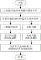
图3是本发明的路径圆弧插补流程图;Fig. 3 is the path circular arc interpolation flow chart of the present invention;
图4是本发明的路径圆弧轴向偏移量图;Fig. 4 is a path arc axial offset diagram of the present invention;
图5是本发明的路径圆弧插补的控制点示意图。FIG. 5 is a schematic diagram of the control points of the path circular interpolation of the present invention.
具体实施方式Detailed ways
为使本发明的上述目的、特征和优点能够更加明显易懂,下面将结合附图和具体的实施例对本发明的技术方案进行详细说明。需要指出的是,所描述的实施例仅仅是本发明一部分实施例,而不是全部的实施例,基于本发明中的实施例,本领域普通技术人员在没有做出创造性劳动前提下所获得的所有其他实施例,都属于本发明保护的范围。In order to make the above objects, features and advantages of the present invention more clearly understood, the technical solutions of the present invention will be described in detail below with reference to the accompanying drawings and specific embodiments. It should be pointed out that the described embodiments are only a part of the embodiments of the present invention, rather than all the embodiments. Based on the embodiments of the present invention, those of ordinary skill in the art can obtain all the Other embodiments fall within the protection scope of the present invention.
本发明提供了一种双机器人协同旋转的路径规划方法,应用于一双机器人协同系统,该系统包括二机器人,二机器人均包含用以共同夹持代加工工件的末端执行器,所述方法用于对机器人末端六轴进行圆弧运动的控制点坐标插补,以实现双机器人协调夹持工件在空间中的多角度对中心旋转。具体的,本发明提供的方法包括:The invention provides a path planning method for coordinated rotation of two robots, which is applied to a two-robot collaborative system. The system includes two robots, and the two robots each include an end effector used to jointly clamp a workpiece for processing. The method is used for The coordinate interpolation of the control point of the circular arc motion is carried out on the six axes of the robot end, so as to realize the multi-angle centering rotation of the workpiece in the space of the double robot coordinated clamping. Specifically, the method provided by the present invention includes:
二机器人相对世界坐标z轴对立放置,依据夹持工件的尺寸设定路径圆弧半径,设置路径偏转角,执行协同旋转工况。The two robots are placed opposite to the z-axis of the world coordinate. According to the size of the workpiece to be clamped, the radius of the path arc is set, the deflection angle of the path is set, and the cooperative rotation condition is executed.
依据机器人平台布置的相对关系及机器人标准D-H参数,获取二机器人末端基坐标的齐次变换矩阵。According to the relative relationship of the robot platform layout and the standard D-H parameters of the robot, the homogeneous transformation matrix of the base coordinates of the end of the two robots is obtained.
分别对二机器人进行坐标旋转插补和基于空间几何的控制点坐标向量插补,生成控制点关于机器人基坐标的齐次变换矩阵。Coordinate rotation interpolation and spatial geometry-based control point coordinate vector interpolation are performed on the two robots respectively, and the homogeneous transformation matrix of the control points with respect to the robot base coordinates is generated.
依据逆动力学,求解控制点齐次变换矩阵对应的关节坐标角度变量。According to the inverse dynamics, the joint coordinate angle variables corresponding to the control point homogeneous transformation matrix are solved.
具体的,在本方法中,将末端基坐标齐次变换矩阵拆分为三维旋转坐标与位置向量两部分。对三维旋转坐标采用基于四元数的旋转插补,对位置向量采用基于空间几何的坐标插补,并整合为控制点关于对应机器人基坐标的齐次变换矩阵。对齐次变换矩阵进行逆动力学求解,输出机器人在控制点处的各轴关节角度值。Specifically, in this method, the end base coordinate homogeneous transformation matrix is split into two parts, the three-dimensional rotation coordinate and the position vector. The quaternion-based rotation interpolation is used for the three-dimensional rotation coordinates, and the spatial geometry-based coordinate interpolation is used for the position vector, which is integrated into the homogeneous transformation matrix of the control points about the corresponding robot base coordinates. Perform inverse kinematics solution on the sub-transformation matrix, and output the joint angle value of each axis of the robot at the control point.
更进一步的,在三位旋转坐标的插补过程中考虑圆弧轴向偏移量的影响,依据圆弧轴向偏移量的限制求解控制点的最大间隔角度值。Furthermore, the influence of the arc axial offset is considered in the interpolation process of the three-dimensional rotation coordinates, and the maximum interval angle value of the control points is obtained according to the limit of the arc axial offset.
参见图1至图5,是本发明的方法应用的一个优选实施例。Referring to Figures 1 to 5, it is a preferred embodiment of the method application of the present invention.
图1为本发明的协同系统平台示意图,主从机器人(图中示意为主机器人1和从机器人2)分别为负载20kg与5kg的工业机器人。两机器人在空间上参照世界坐标系z轴对立布置,机器人末端装载末端执行器(本实施例中具体为气动吸盘),同时夹持工件执行工况。FIG. 1 is a schematic diagram of the collaborative system platform of the present invention. The master and slave robots (the master robot 1 and the slave robot 2 are shown in the figure) are industrial robots with loads of 20kg and 5kg, respectively. The two robots are arranged oppositely in space with reference to the z-axis of the world coordinate system, and the end of the robot is loaded with an end effector (specifically, a pneumatic suction cup in this embodiment), and simultaneously clamps the workpiece to perform the working condition.
图2示出了双机器人协同平台的简化结构示意图。平面简化结构主要描述双机器人在世界坐标系中的相对位置关系及D-H参数属性。存在x轴间距l与y轴间距b。机器人1底座高度为h1,机器人2底座高度为h2;左右两侧机器人的关节连杆长度分别为ai和a’i,偏移量分别为di和d’i。Figure 2 shows a simplified schematic diagram of the dual-robot collaborative platform. The plane simplified structure mainly describes the relative position relationship and DH parameter attributes of the dual robots in the world coordinate system. There is an x-axis distance l and a y-axis distance b. The height of the base of robot 1 is h1 , and the height of the base of robot 2 is h2 ; the lengths of the joint links of the left and right robots are ai and a'i , and the offsets are di and d'i , respectively.
图3示出了本发明的路径圆弧插补流程图,由既定路径偏转角与工件尺寸决定的路径圆弧半径,计算初始控制点的齐次变换矩阵。Fig. 3 shows the flow chart of the path arc interpolation of the present invention, the homogeneous transformation matrix of the initial control point is calculated from the path arc radius determined by the predetermined path deflection angle and the workpiece size.
图4为路径圆弧的最大轴向偏移量示意图。当采用movej直线运动指令进行圆弧路径规划时,存在路径圆弧轴向偏差。实验平台末端采用柔性弹性气爪,弹性极限为0.01m。路径圆弧的最大轴向偏移量设置为0.005m。控制点等分路径圆弧,最大轴向偏移量产生在两个相邻控制点的中心线上。Figure 4 is a schematic diagram of the maximum axial offset of the path arc. When the movej linear motion command is used to plan the arc path, there is an axial deviation of the path arc. The end of the experimental platform adopts a flexible elastic air gripper with an elastic limit of 0.01m. The maximum axial offset of the path arc is set to 0.005m. The control point bisects the path arc, and the maximum axial offset is generated on the centerline of two adjacent control points.
图5为路径圆弧插补的控制点示意图。由初始控制点的齐次变换矩阵提取三维旋转矩阵

(1)将T3转化为四元数形式的Q0=q0+q1i+q2j+q3k,其中i、j、k为虚数单位,q0、q1、q2、q3是具体变量值,设置控制点的四元数表达式为Qi=[wi,(xi,yi,zi)]T,wi是实部变量值,xi,yi,zi是虚部变量值,依据Qi=Q′*Q0*Q′-1及四元数乘法的计算公式,代入控制点的最大圆弧最大角度,得到各旋转后控制点的四元数,转化为任意控制点处的旋转矩阵。(1) Convert T3 to Q0 =q0 +q1 i+q2 j+q3 k in quaternion form, where i, j, and k are imaginary units, q0 , q1 , q2 , q3 is the specific variable value, the quaternion expression for setting the control point is Qi =[wi ,(xi ,yi ,zi )]T , wi is the real variable value, xi ,yi , zi is the value of the imaginary part variable, according to the calculation formula of Qi=Q′*Q0 *Q′-1 and quaternion multiplication, substitute the maximum arc angle of the control point to obtain the quaternion of each rotated control point number, converted to a rotation matrix at any control point.
(2)控制点相对坐标系P的坐标偏移量同样可由各坐标轴方向上的偏移向量px,py,pz表示,将控制点的坐标向量表示为
优选的,初始控制齐次变换矩阵的求解方法为:旋转路径相对xpzp平面偏转角度为α,路径圆弧半径为r,路径起始点坐标P0先由yp顺时针旋转90°,然后相对z轴顺时针旋转(α+90°),再沿z轴轴向平移-r m,(0≤m<360)。P0相对P点坐标系的齐次变换矩阵矩阵表示为:
优选的,圆弧控制点的最大角度值满足:


优选的,初始控制点Q0的四元数表示一般形式为:Preferably, the general form of the quaternion representation of the initial control point Q0 is:

优选的,四元数绕轴旋转角度为n,旋转轴的相关四元数表示为:Preferably, the rotation angle of the quaternion around the axis is n, and the relevant quaternion of the rotation axis is expressed as:
优选的,四元数Qi=[wi,(xi,yi,zi)]T姿态旋转的一般形式表示为:Preferably, the quaternion Qi =[wi ,(xi ,yi ,zi )] The general form ofT attitude rotation is expressed as:

四元数转换为旋转矩阵的公式为:The formula for converting a quaternion to a rotation matrix is:

优选的,控制点相对点P坐标系坐标向量的各元素满足关系:
优选的,两机器人控制点关于机器人基座标的齐次变换矩阵可表示为:Preferably, the homogeneous transformation matrix of the two robot control points with respect to the robot base can be expressed as:

L为两机器人x轴方向相距,b为y轴方向相距,h1为左侧机器人的底座高度为,h2为右侧机器人的底座高度。L is the distance between the two robots in the x-axis direction, b is the distance in the y- axis direction,h1 is the height of the base of the left robot, and h2 is the base height of the right robot.
本发明相应提供了一种双机器人协同旋转的路径规划装置,包括机器人坐标标定模块、控制点插补模块以及逆动力学求解模块;The invention correspondingly provides a path planning device for coordinated rotation of two robots, including a robot coordinate calibration module, a control point interpolation module and an inverse dynamics solution module;
所述机器人坐标标定模块,用于标定单位机器人的基坐标与末端轴坐标属性,并在机器人协同系统中建立相对坐标关系;The robot coordinate calibration module is used to calibrate the base coordinate and end axis coordinate attributes of the unit robot, and establish a relative coordinate relationship in the robot collaborative system;
控制点插补模块,用于依据机器人末端齐次变换矩阵,针对路径圆弧的插补需求,执行对二机器人的圆弧路径插补;The control point interpolation module is used to execute the circular path interpolation of the two robots according to the homogeneous transformation matrix of the robot end and according to the interpolation requirements of the path circular arc;
所述控制点插补模块,包括初始控制点单元、坐标旋转插补单元、坐标向量位置插补单元。The control point interpolation module includes an initial control point unit, a coordinate rotation interpolation unit, and a coordinate vector position interpolation unit.
所述初始控制点求解器包括路径圆弧建模模块和初始控制点坐标系的齐次变换矩阵矩阵求解模块。用于对路径圆弧进行建模并求解初始控制点的齐次变换矩阵。The initial control point solver includes a path arc modeling module and a homogeneous transformation matrix matrix solving module for the initial control point coordinate system. Homogeneous transformation matrix used to model path arcs and solve for initial control points.
所述坐标旋转插补求单元包括圆弧轴向偏差求解模块、旋转矩阵绕轴旋转的四元数插补模块。用于计算满足圆弧轴向偏差要求的最大控制点间隔角,并据此求解控制点的坐标旋转矩阵。The coordinate rotation interpolation calculation unit includes a circular arc axial deviation calculation module and a quaternion interpolation module for rotating the rotation matrix around the axis. It is used to calculate the maximum control point interval angle that meets the requirements of the arc axial deviation, and solve the coordinate rotation matrix of the control points accordingly.
所述坐标向量位置插补单元包括,控制点各轴向偏移量求解模块,控制点位置插补模块。用于计算控制点相对旋转中心的轴向偏移量并生成控制点的位置向量。The coordinate vector position interpolation unit includes a control point offset solution module for each axial direction, and a control point position interpolation module. Used to calculate the axial offset of the control point from the center of rotation and generate the position vector of the control point.
逆动力学求解模块,用于合并各控制点的齐次变换矩阵,求解对应六轴的关节角度变化量。The inverse dynamics solution module is used to combine the homogeneous transformation matrices of each control point to solve the joint angle change corresponding to the six axes.
本发明的双机器人协同旋转的路径规划方法和装置,有无差别适用于多种机器人的四元数与旋转矩阵的路径圆弧插补方法,该方法可计算出路径圆弧轨迹的插补控制点,插补路径较平滑,符合关节角限制,圆度误差低。实现了双机器人协同搬运工件在空间中多角度对中心旋转,具有普遍适用性。The path planning method and device for coordinated rotation of two robots of the present invention are applicable to the path circular interpolation method of the quaternion and rotation matrix of various robots, and the method can calculate the interpolation control of the path circular arc trajectory. point, the interpolation path is relatively smooth, conforms to the joint angle limit, and the roundness error is low. It realizes the multi-angle rotation of the center in the space for the two robots to carry the workpiece cooperatively, and has universal applicability.
以上所述实施例仅表达了本发明的几种实施方式,其描述较为具体和详细,但并不能因此而理解为对本发明专利范围的限制。应当指出的是,对于本领域的普通技术人员来说,在不脱离本发明构思的前提下,还可以做出若干变形和改进,这些都属于本发明的保护范围。因此,本发明专利的保护范围应以所附权利要求为准。The above-mentioned embodiments only represent several embodiments of the present invention, and the descriptions thereof are specific and detailed, but should not be construed as a limitation on the scope of the patent of the present invention. It should be pointed out that for those skilled in the art, without departing from the concept of the present invention, several modifications and improvements can be made, which all belong to the protection scope of the present invention. Therefore, the protection scope of the patent of the present invention should be subject to the appended claims.
Claims (10)


Priority Applications (1)
| Application Number | Priority Date | Filing Date | Title |
|---|---|---|---|
| CN201910967429.0ACN110757454B (en) | 2019-10-12 | 2019-10-12 | Path planning method and device for cooperative rotation of double robots |
Applications Claiming Priority (1)
| Application Number | Priority Date | Filing Date | Title |
|---|---|---|---|
| CN201910967429.0ACN110757454B (en) | 2019-10-12 | 2019-10-12 | Path planning method and device for cooperative rotation of double robots |
Publications (2)
| Publication Number | Publication Date |
|---|---|
| CN110757454Atrue CN110757454A (en) | 2020-02-07 |
| CN110757454B CN110757454B (en) | 2022-08-16 |
Family
ID=69331650
Family Applications (1)
| Application Number | Title | Priority Date | Filing Date |
|---|---|---|---|
| CN201910967429.0AExpired - Fee RelatedCN110757454B (en) | 2019-10-12 | 2019-10-12 | Path planning method and device for cooperative rotation of double robots |
Country Status (1)
| Country | Link |
|---|---|
| CN (1) | CN110757454B (en) |
Cited By (17)
| Publication number | Priority date | Publication date | Assignee | Title |
|---|---|---|---|---|
| CN111844045A (en)* | 2020-08-03 | 2020-10-30 | 许昌学院 | A dual-machine collaborative heavy-duty palletizing robot |
| CN112496582A (en)* | 2020-11-23 | 2021-03-16 | 博迈科海洋工程股份有限公司 | Ocean engineering complex node multi-robot welding cooperative control method |
| CN113524183A (en)* | 2021-07-14 | 2021-10-22 | 广东智源机器人科技有限公司 | Relative position obtaining method, robot arm control method, and robot arm system |
| CN113733038A (en)* | 2021-11-02 | 2021-12-03 | 季华科技有限公司 | Robot cooperative action control method, device, system and storage medium |
| CN114115113A (en)* | 2021-10-15 | 2022-03-01 | 上海发那科机器人有限公司 | Intelligent pipe bending track generation method based on double-robot pipe bending system |
| CN114193450A (en)* | 2021-12-10 | 2022-03-18 | 南京我乐家居智能制造有限公司 | Double-station robot feeding operation precision intelligent analysis and regulation method based on artificial intelligence |
| WO2022068926A1 (en)* | 2020-09-30 | 2022-04-07 | 杭州海康机器人技术有限公司 | Method and apparatus for realizing simultaneous movement of multiple robots, and storage medium |
| CN114310877A (en)* | 2021-03-09 | 2022-04-12 | 香港科能有限公司 | Robot Collaborative System and Its Application and Machining Accuracy Evaluation Method |
| CN114454155A (en)* | 2020-11-10 | 2022-05-10 | 广东博智林机器人有限公司 | Robot control method, robot control device, computer equipment, medium and robot |
| WO2022241806A1 (en)* | 2021-05-19 | 2022-11-24 | 广州先进技术研究所 | Dual-robot force/position multielement data driving method based on reinforcement learning |
| CN115890653A (en)* | 2022-09-28 | 2023-04-04 | 华中科技大学 | Cooperative control method, device and readable medium of dual-arm robot based on multi-channel |
| CN117340881A (en)* | 2023-10-24 | 2024-01-05 | 南京南自信息技术有限公司 | Real-time planning method for tail end track of mechanical arm |
| CN117381771A (en)* | 2023-09-22 | 2024-01-12 | 东华大学 | A trajectory calculation method and system based on dual-robot collaborative weaving |
| CN117428791A (en)* | 2023-12-21 | 2024-01-23 | 江西求是高等研究院 | Inverse kinematics solving method and system for shoulder four-axis rehabilitation robot |
| CN117601137A (en)* | 2024-01-24 | 2024-02-27 | 海克斯康软件技术(青岛)有限公司 | Multi-robot joint control method |
| CN118664599A (en)* | 2024-07-19 | 2024-09-20 | 成都飞机工业(集团)有限责任公司 | Automatic planning method, device, equipment and medium for rotation angle of tool in robot hole making |
| CN119048588A (en)* | 2024-10-29 | 2024-11-29 | 杭州芯控智能科技有限公司 | Robot public reachable pose solving method, system and readable storage medium |
Citations (10)
| Publication number | Priority date | Publication date | Assignee | Title |
|---|---|---|---|---|
| US20100331855A1 (en)* | 2005-05-16 | 2010-12-30 | Intuitive Surgical, Inc. | Efficient Vision and Kinematic Data Fusion For Robotic Surgical Instruments and Other Applications |
| CN103568012A (en)* | 2013-10-24 | 2014-02-12 | 安徽埃夫特智能装备有限公司 | Method for planning biplanar swing arc track of arc welding robot |
| CN103901898A (en)* | 2014-03-28 | 2014-07-02 | 哈尔滨工程大学 | Inverse-kinematics universal solving method of robot with multi-degree of freedom |
| CN105773620A (en)* | 2016-04-26 | 2016-07-20 | 南京工程学院 | Track planning and control method of free curve of industrial robot based on double quaternions |
| US20160221189A1 (en)* | 2013-08-27 | 2016-08-04 | Cognibotics Ab | Method and system for determination of at least one property of a manipulator |
| CN106671079A (en)* | 2015-11-06 | 2017-05-17 | 中国科学院沈阳计算技术研究所有限公司 | Motion control method for welding robot in coordination with positioner |
| CN106826829A (en)* | 2017-02-22 | 2017-06-13 | 武汉工程大学 | A kind of industrial robot fairing trace generator method of Controllable Error |
| CN106926241A (en)* | 2017-03-20 | 2017-07-07 | 深圳市智能机器人研究院 | A kind of the tow-armed robot assembly method and system of view-based access control model guiding |
| CN107253191A (en)* | 2017-05-22 | 2017-10-17 | 广州中国科学院先进技术研究所 | A kind of double mechanical arms system and its control method for coordinating |
| US20190358817A1 (en)* | 2016-11-10 | 2019-11-28 | Cognibotics Ab | System and method for instructing a robot |
- 2019
- 2019-10-12CNCN201910967429.0Apatent/CN110757454B/ennot_activeExpired - Fee Related
Patent Citations (10)
| Publication number | Priority date | Publication date | Assignee | Title |
|---|---|---|---|---|
| US20100331855A1 (en)* | 2005-05-16 | 2010-12-30 | Intuitive Surgical, Inc. | Efficient Vision and Kinematic Data Fusion For Robotic Surgical Instruments and Other Applications |
| US20160221189A1 (en)* | 2013-08-27 | 2016-08-04 | Cognibotics Ab | Method and system for determination of at least one property of a manipulator |
| CN103568012A (en)* | 2013-10-24 | 2014-02-12 | 安徽埃夫特智能装备有限公司 | Method for planning biplanar swing arc track of arc welding robot |
| CN103901898A (en)* | 2014-03-28 | 2014-07-02 | 哈尔滨工程大学 | Inverse-kinematics universal solving method of robot with multi-degree of freedom |
| CN106671079A (en)* | 2015-11-06 | 2017-05-17 | 中国科学院沈阳计算技术研究所有限公司 | Motion control method for welding robot in coordination with positioner |
| CN105773620A (en)* | 2016-04-26 | 2016-07-20 | 南京工程学院 | Track planning and control method of free curve of industrial robot based on double quaternions |
| US20190358817A1 (en)* | 2016-11-10 | 2019-11-28 | Cognibotics Ab | System and method for instructing a robot |
| CN106826829A (en)* | 2017-02-22 | 2017-06-13 | 武汉工程大学 | A kind of industrial robot fairing trace generator method of Controllable Error |
| CN106926241A (en)* | 2017-03-20 | 2017-07-07 | 深圳市智能机器人研究院 | A kind of the tow-armed robot assembly method and system of view-based access control model guiding |
| CN107253191A (en)* | 2017-05-22 | 2017-10-17 | 广州中国科学院先进技术研究所 | A kind of double mechanical arms system and its control method for coordinating |
Non-Patent Citations (3)
| Title |
|---|
| MIN-XIU KONG: "Application of orientation interpolation of robot using unit quaternion", 《APPLICATION OF ORIENTATION INTERPOLATION OF ROBOT USING UNIT QUATERNION》* |
| 任秉银: "机械手空间圆弧位姿轨迹规划算法的实现", 《机械手空间圆弧位姿轨迹规划算法的实现》* |
| 包翔宇: "双机器人协同旋转过程中的四元数插补路径规划", 《双机器人协同旋转过程中的四元数插补路径规划》* |
Cited By (25)
| Publication number | Priority date | Publication date | Assignee | Title |
|---|---|---|---|---|
| CN111844045A (en)* | 2020-08-03 | 2020-10-30 | 许昌学院 | A dual-machine collaborative heavy-duty palletizing robot |
| CN111844045B (en)* | 2020-08-03 | 2023-01-24 | 许昌学院 | Double-machine collaborative heavy-load palletizing robot |
| WO2022068926A1 (en)* | 2020-09-30 | 2022-04-07 | 杭州海康机器人技术有限公司 | Method and apparatus for realizing simultaneous movement of multiple robots, and storage medium |
| CN114454155A (en)* | 2020-11-10 | 2022-05-10 | 广东博智林机器人有限公司 | Robot control method, robot control device, computer equipment, medium and robot |
| CN112496582A (en)* | 2020-11-23 | 2021-03-16 | 博迈科海洋工程股份有限公司 | Ocean engineering complex node multi-robot welding cooperative control method |
| CN114310877A (en)* | 2021-03-09 | 2022-04-12 | 香港科能有限公司 | Robot Collaborative System and Its Application and Machining Accuracy Evaluation Method |
| CN114310877B (en)* | 2021-03-09 | 2024-05-07 | 香港科能有限公司 | Robot cooperative system and application and machining precision evaluation method thereof |
| WO2022241806A1 (en)* | 2021-05-19 | 2022-11-24 | 广州先进技术研究所 | Dual-robot force/position multielement data driving method based on reinforcement learning |
| CN113524183A (en)* | 2021-07-14 | 2021-10-22 | 广东智源机器人科技有限公司 | Relative position obtaining method, robot arm control method, and robot arm system |
| CN114115113A (en)* | 2021-10-15 | 2022-03-01 | 上海发那科机器人有限公司 | Intelligent pipe bending track generation method based on double-robot pipe bending system |
| CN114115113B (en)* | 2021-10-15 | 2023-11-21 | 上海发那科机器人有限公司 | Intelligent pipe bending track generation method based on double-robot pipe bending system |
| CN113733038A (en)* | 2021-11-02 | 2021-12-03 | 季华科技有限公司 | Robot cooperative action control method, device, system and storage medium |
| CN114193450A (en)* | 2021-12-10 | 2022-03-18 | 南京我乐家居智能制造有限公司 | Double-station robot feeding operation precision intelligent analysis and regulation method based on artificial intelligence |
| CN114193450B (en)* | 2021-12-10 | 2022-12-30 | 南京我乐家居智能制造有限公司 | Double-station robot feeding operation precision intelligent analysis and regulation method based on artificial intelligence |
| CN115890653A (en)* | 2022-09-28 | 2023-04-04 | 华中科技大学 | Cooperative control method, device and readable medium of dual-arm robot based on multi-channel |
| CN117381771A (en)* | 2023-09-22 | 2024-01-12 | 东华大学 | A trajectory calculation method and system based on dual-robot collaborative weaving |
| CN117340881A (en)* | 2023-10-24 | 2024-01-05 | 南京南自信息技术有限公司 | Real-time planning method for tail end track of mechanical arm |
| CN117428791A (en)* | 2023-12-21 | 2024-01-23 | 江西求是高等研究院 | Inverse kinematics solving method and system for shoulder four-axis rehabilitation robot |
| CN117428791B (en)* | 2023-12-21 | 2024-03-01 | 江西求是高等研究院 | Inverse kinematics solving method and system for shoulder four-axis rehabilitation robot |
| CN117601137A (en)* | 2024-01-24 | 2024-02-27 | 海克斯康软件技术(青岛)有限公司 | Multi-robot joint control method |
| CN117601137B (en)* | 2024-01-24 | 2024-03-29 | 海克斯康软件技术(青岛)有限公司 | Multi-robot joint control method |
| CN118664599A (en)* | 2024-07-19 | 2024-09-20 | 成都飞机工业(集团)有限责任公司 | Automatic planning method, device, equipment and medium for rotation angle of tool in robot hole making |
| CN118664599B (en)* | 2024-07-19 | 2025-08-12 | 成都飞机工业(集团)有限责任公司 | Automatic planning method, device, equipment and medium for rotation angle of tool in robot hole making |
| CN119048588A (en)* | 2024-10-29 | 2024-11-29 | 杭州芯控智能科技有限公司 | Robot public reachable pose solving method, system and readable storage medium |
| CN119048588B (en)* | 2024-10-29 | 2025-01-07 | 杭州芯控智能科技有限公司 | Robot public reachable pose solving method, system and readable storage medium |
Also Published As
| Publication number | Publication date |
|---|---|
| CN110757454B (en) | 2022-08-16 |
Similar Documents
| Publication | Publication Date | Title |
|---|---|---|
| CN110757454B (en) | Path planning method and device for cooperative rotation of double robots | |
| CN109895101B (en) | A method for obtaining unique numerical solution of inverse kinematics of articulated manipulator | |
| CN109159151B (en) | Mechanical arm space trajectory tracking dynamic compensation method and system | |
| CN107589934B (en) | Solving method for inverse kinematics analytic solution of joint type mechanical arm | |
| CN108818535B (en) | Robot 3D vision hand-eye calibration method | |
| Sun et al. | Analytical inverse kinematic solution using the DH method for a 6-DOF robot | |
| CN107116542B (en) | A control method and system for a six-joint industrial robot passing a posture singularity | |
| CN112123341B (en) | Robot double arm coordinated motion control method, device and electronic device | |
| CN105014677A (en) | Visual mechanical arm control device and method based on Camshift visual tracking and D-H modeling algorithms | |
| CN110712203A (en) | 7-degree-of-freedom mechanical arm inverse kinematics solving algorithm | |
| CN110722562B (en) | Space Jacobian matrix construction method for machine ginseng number identification | |
| CN110962127B (en) | Auxiliary calibration device for tail end pose of mechanical arm and calibration method thereof | |
| CN105643619B (en) | A kind of industrial robot instrument posture control method of use framework description | |
| CN108481324B (en) | Inverse solution engineering of eight-axis multifunctional mechanical arm and collision detection algorithm thereof | |
| CN107253191B (en) | Double-mechanical-arm system and coordination control method thereof | |
| CN105522577A (en) | Method and device used for planning Descartes trajectory of five-axis bending robot | |
| Long et al. | Robotic arm simulation by using matlab and robotics toolbox for industry application | |
| CN107727026A (en) | Calibration method of workpiece coordinate system for cooperative work of duplex robot | |
| CN107791248A (en) | Control method based on the six degree of freedom serial manipulator for being unsatisfactory for pipper criterions | |
| CN111791234A (en) | Anti-collision control algorithm for working positions of multiple robots in narrow space | |
| WO2016008215A1 (en) | 5-axis and 6-axis mixing control method for industrial robot and system thereof | |
| Yahui et al. | Kinematic cooperation analysis and trajectory teaching in multiple robots system for welding | |
| Bian et al. | Kinematic analysis and simulation of 6-DOF industrial robot capable of picking up die-casting products | |
| CN114932545A (en) | Industrial robot inverse solution method based on geometric method | |
| WO2024254962A1 (en) | Mechanical arm control zero point calibration method and related apparatus |
Legal Events
| Date | Code | Title | Description |
|---|---|---|---|
| PB01 | Publication | ||
| PB01 | Publication | ||
| SE01 | Entry into force of request for substantive examination | ||
| SE01 | Entry into force of request for substantive examination | ||
| GR01 | Patent grant | ||
| GR01 | Patent grant | ||
| CF01 | Termination of patent right due to non-payment of annual fee | Granted publication date:20220816 |