CN110753874A - Augmented reality system - Google Patents
Augmented reality systemDownload PDFInfo
- Publication number
- CN110753874A CN110753874ACN201880037553.0ACN201880037553ACN110753874ACN 110753874 ACN110753874 ACN 110753874ACN 201880037553 ACN201880037553 ACN 201880037553ACN 110753874 ACN110753874 ACN 110753874A
- Authority
- CN
- China
- Prior art keywords
- augmented reality
- reality system
- user
- slats
- suppression layer
- Prior art date
- Legal status (The legal status is an assumption and is not a legal conclusion. Google has not performed a legal analysis and makes no representation as to the accuracy of the status listed.)
- Granted
Links
Images


Classifications
- G—PHYSICS
- G02—OPTICS
- G02B—OPTICAL ELEMENTS, SYSTEMS OR APPARATUS
- G02B27/00—Optical systems or apparatus not provided for by any of the groups G02B1/00 - G02B26/00, G02B30/00
- G02B27/01—Head-up displays
- G02B27/017—Head mounted
- G02B27/0172—Head mounted characterised by optical features
- G—PHYSICS
- G02—OPTICS
- G02B—OPTICAL ELEMENTS, SYSTEMS OR APPARATUS
- G02B27/00—Optical systems or apparatus not provided for by any of the groups G02B1/00 - G02B26/00, G02B30/00
- G02B27/0018—Optical systems or apparatus not provided for by any of the groups G02B1/00 - G02B26/00, G02B30/00 with means for preventing ghost images
- G—PHYSICS
- G02—OPTICS
- G02B—OPTICAL ELEMENTS, SYSTEMS OR APPARATUS
- G02B27/00—Optical systems or apparatus not provided for by any of the groups G02B1/00 - G02B26/00, G02B30/00
- G02B27/01—Head-up displays
- G02B27/0101—Head-up displays characterised by optical features
- G—PHYSICS
- G02—OPTICS
- G02B—OPTICAL ELEMENTS, SYSTEMS OR APPARATUS
- G02B27/00—Optical systems or apparatus not provided for by any of the groups G02B1/00 - G02B26/00, G02B30/00
- G02B27/01—Head-up displays
- G02B27/0101—Head-up displays characterised by optical features
- G02B2027/0118—Head-up displays characterised by optical features comprising devices for improving the contrast of the display / brillance control visibility
- G02B2027/012—Head-up displays characterised by optical features comprising devices for improving the contrast of the display / brillance control visibility comprising devices for attenuating parasitic image effects
- G—PHYSICS
- G02—OPTICS
- G02B—OPTICAL ELEMENTS, SYSTEMS OR APPARATUS
- G02B27/00—Optical systems or apparatus not provided for by any of the groups G02B1/00 - G02B26/00, G02B30/00
- G02B27/01—Head-up displays
- G02B27/0101—Head-up displays characterised by optical features
- G02B2027/013—Head-up displays characterised by optical features comprising a combiner of particular shape, e.g. curvature
- G—PHYSICS
- G02—OPTICS
- G02B—OPTICAL ELEMENTS, SYSTEMS OR APPARATUS
- G02B27/00—Optical systems or apparatus not provided for by any of the groups G02B1/00 - G02B26/00, G02B30/00
- G02B27/01—Head-up displays
- G02B27/017—Head mounted
- G02B2027/0178—Eyeglass type
- G—PHYSICS
- G02—OPTICS
- G02B—OPTICAL ELEMENTS, SYSTEMS OR APPARATUS
- G02B2207/00—Coding scheme for general features or characteristics of optical elements and systems of subclass G02B, but not including elements and systems which would be classified in G02B6/00 and subgroups
- G02B2207/123—Optical louvre elements, e.g. for directional light blocking
- G—PHYSICS
- G02—OPTICS
- G02B—OPTICAL ELEMENTS, SYSTEMS OR APPARATUS
- G02B6/00—Light guides; Structural details of arrangements comprising light guides and other optical elements, e.g. couplings
- G02B6/24—Coupling light guides
- G02B6/26—Optical coupling means
- G02B6/34—Optical coupling means utilising prism or grating
Landscapes
- Physics & Mathematics (AREA)
- General Physics & Mathematics (AREA)
- Optics & Photonics (AREA)
Abstract
Translated fromChinese
Description
Translated fromChinese技术领域technical field
本发明涉及一种增强现实系统以及一种用于改善在诸如日光的强光条件下的使用的技术。The present invention relates to an augmented reality system and a technique for improving use in bright light conditions such as sunlight.
背景技术Background technique
头戴式增强现实系统可以戴在用户的头上以通过供应额外光来增强用户对真实世界的感知。已知头戴式系统包含眼镜及头盔结构。增强现实系统也包含可以在交通工具中、诸如在汽车、卡车中或也在飞机驾驶舱中实施的抬头显示器。Head-mounted augmented reality systems can be worn on the user's head to enhance the user's perception of the real world by supplying additional light. Known head-mounted systems include eyeglasses and helmet structures. Augmented reality systems also include head-up displays that can be implemented in vehicles, such as in cars, trucks, or also in aircraft cockpits.
增强现实光可以使用波导结构提供至用户。衍射光栅定位于波导上或波导中以将来自投影机的光耦合至波导中。接着,可以使用另外的衍射光栅结构将光自波导且朝向用户耦出。可以采用其他增强现实技术来产生类似结果。例如,棱镜投影机或基于棱镜的设计的增强现实系统可以使用多个透镜或棱镜来控制光自显示部件至用户的光学路径。Augmented reality light can be provided to the user using a waveguide structure. Diffraction gratings are positioned on or in the waveguide to couple light from the projector into the waveguide. Then, additional diffraction grating structures can be used to couple light out of the waveguide and towards the user. Other augmented reality techniques can be employed to produce similar results. For example, a prism projector or an augmented reality system based on a prism-based design may use multiple lenses or prisms to control the optical path of light from the display component to the user.
在这些应用中,光学部件、诸如波导或棱镜通常为透明的,使得用户可以观看来自投影机的光以及来自他们的外部环境的光。In these applications, optical components, such as waveguides or prisms, are often transparent so that users can view light from the projector as well as light from their external environment.
然而,许多增强现实系统在它们在包含日光的强光条件下使用时存在困难。这些困难可以是由于意在用于控制来自投影机的光的光学部件也可以与来自外部世界的光相互作用而产生。However, many augmented reality systems have difficulties when they are used in bright light conditions including sunlight. These difficulties can arise from the fact that optical components intended to control light from the projector can also interact with light from the outside world.
具体地,已发现,当来自外部源的入射光线遇到光学部件时,一些光线可以朝向用户的眼睛衍射或折射。如果光源足够明亮,则这些杂散光线可以在用户的视野内产生不受欢迎的彩虹效应。该彩虹效可以减损用户对外部环境的视觉或降低增强计算机产生的信息的可见度。当外部环境中存在的强光相对于用户的视线成高角度时,彩虹效应尤为严重;成问题光源的示例包含成高仰角的聚光灯、内部环境中的吸顶灯、或太阳在高空中且用户的视线在水平面上时的太阳。In particular, it has been found that when incident light rays from external sources encounter optical components, some of the light rays can be diffracted or refracted towards the user's eye. If the light source is bright enough, these stray lights can create an undesired rainbow effect in the user's field of view. This rainbow effect can detract from the user's vision of the external environment or reduce the visibility of enhanced computer-generated information. The rainbow effect is especially severe when strong light is present in the external environment at a high angle relative to the user's line of sight; examples of problematic light sources include spotlights at high elevation angles, ceiling lights in an internal environment, or the sun high in the sky and the user's The sun when the line of sight is on a horizontal plane.
类似地,特定增强现实技术不可或缺的反射或折射结构也可能遭受类似不想要的射线偏转的影响。Similarly, reflective or refractive structures that are integral to certain augmented reality technologies may suffer from similar unwanted ray deflections.
发明内容SUMMARY OF THE INVENTION
本发明的目的是改善在不同照明条件下使用增强现实系统的能力,并且减少用户所经历的不期望的光学效应。It is an object of the present invention to improve the ability to use augmented reality systems in different lighting conditions and to reduce unwanted optical effects experienced by users.
根据本发明的一方面,提供一种增强现实系统,其包括:投影机;大致透明的光学部件,其布置成接收来自该投影机的光并且将增强现实光提供至用户的假想眼睛位置;及杂散光抑制层,其用于该大致透明的光学部件,其中,该杂散光抑制层包括多个板条,其中,该多个板条各自包括轴线,并且其中,该多个板条的轴以多个各自角度布置,其中,该多个板条的轴各自被引导朝向用户的假想眼睛位置。According to an aspect of the present invention, there is provided an augmented reality system comprising: a projector; substantially transparent optical components arranged to receive light from the projector and provide augmented reality light to an imaginary eye location of a user; and a stray light suppression layer for the substantially transparent optical component, wherein the stray light suppression layer includes a plurality of slats, wherein each of the plurality of slats includes an axis, and wherein the axes of the plurality of slats are A plurality of respective angular arrangements, wherein the axes of the plurality of slats are each directed towards the user's imaginary eye position.
以这种方式,用户可以在具有减少的杂散光问题的情况下在明亮外部条件下、例如,在具有极少云量的晴天户外环境中观看经投影增强现实影像。杂散光抑制层可以有利地减少外部光的高角度入射射线到达大致透明的光学部件。这种对杂散光的抑制又可以减少可以由大致透明的光学部件朝向用户的眼睛衍射或折射的入射光量。有利地,这减少诸如彩虹的不期望的光学效应。类似地,其他增强现实技术可以同样受益。In this manner, a user can view projected augmented reality imagery in bright external conditions, eg, in a sunny outdoor environment with little cloud cover, with reduced stray light problems. Stray light suppression layers can advantageously reduce high angle incident rays of external light from reaching substantially transparent optical components. This suppression of stray light, in turn, can reduce the amount of incident light that can be diffracted or refracted by the substantially transparent optical components toward the user's eye. Advantageously, this reduces undesired optical effects such as rainbows. Similarly, other augmented reality technologies could benefit as well.
增强现实系统可以为头戴式增强现实系统,其中,该增强现实系统还包括头部支架,该头部支架构造成将大致透明的光学部件间隔在相对于用户的假想眼睛位置的位置处。The augmented reality system may be a head-mounted augmented reality system, wherein the augmented reality system further includes a head support configured to space the substantially transparent optical components at positions relative to the user's imaginary eye positions.
头部支架可以帮助定位大致透明的光学部件,使得板条定向成使得它们的轴被引导朝向用户的假想眼睛位置。用户的假想眼睛位置可以表示共同焦点,由此可以判定多个各自角度。在使用中,由于不同头部形状,相同头部支架可以针对不同用户的眼睛将大致透明的光学部件间隔在不同位置处。优选地,轴定向成朝向假想眼睛位置,该位置可以判定为用户眼睛的平均预期位置。The head support can help position the generally transparent optics so that the slats are oriented such that their axes are directed towards the user's imaginary eye position. The user's imaginary eye position may represent a common focus, whereby a plurality of respective angles may be determined. In use, the same head support may space the substantially transparent optics at different locations for different users' eyes due to different head shapes. Preferably, the axis is oriented towards an imaginary eye position, which can be determined as the average expected position of the user's eyes.
优选地,从用户的假想眼睛位置判定与假想前视方向的多个角度。以这种方式,可以通过假想前视方向与其中用户的假想眼睛位置充当共同焦点的轴之间的角度判定板条的轴线。各角度可以为用于判定线性板条的轴的平面角度。或者,各角度可以为用于判定具有弯曲部分的板条的立体角度。在另一示例中,一些角度可以为相对于用户的假想眼睛位置水平安置的线性板条的平面角度,并且其他角度可以为相对于用户的假想眼睛位置竖直安置的线性板条的平面角度。Preferably, multiple angles to the imaginary forward looking direction are determined from the user's imaginary eye position. In this way, the axis of the slats can be determined by the angle between the imaginary forward looking direction and the axis in which the user's imaginary eye position acts as a common focus. Each angle may be a plane angle used to determine the axis of the linear slat. Alternatively, each angle may be a solid angle for determining a slat having a curved portion. In another example, some angles may be the plane angles of the linear slats positioned horizontally relative to the user's imaginary eye position, and other angles may be the plane angles of the linear slats positioned vertically relative to the user's imaginary eye position.
各板条的至少一部分可以为弯曲的。以这种方式,多个板条可以阻挡来自水平方向及竖直方向两者的高角度入射光。各板条可以具有带有弯曲端部的笔直水平部段,其中,端部朝向大致透明的光学部件的水平中心线(与用户的假想眼睛位置或视线的中心线一致)弯曲。At least a portion of each slat may be curved. In this way, the plurality of slats can block high angle incident light from both horizontal and vertical directions. Each slat may have a straight horizontal section with curved ends, wherein the ends are curved towards the horizontal centerline of the substantially transparent optic (coinciding with the user's imaginary eye position or centerline of line of sight).
各板条可以为围绕假想前视方向的平截头体,使得多个板条形成一组嵌套平截头体。多个板条中的各平截头体可以为截头圆锥体。多个圆形板条将看似沿假想前视位置至用户的一组同心圆。或者,各板条可以为丸状,其中,板条具有在各端部上具有半平截头体的两个平面部段。在另一示例中,各平截头体可以为截头棱锥体。Each slat may be a frustum about an imaginary forward-looking direction, such that a plurality of slats form a set of nested frustums. Each frustum in the plurality of slats may be frustoconical. The multiple circular slats will appear to be a set of concentric circles along an imaginary forward looking position to the user. Alternatively, each slat may be pellet-shaped, wherein the slat has two planar sections with semi-frustums on each end. In another example, each frustum may be a truncated pyramid.
优选地,各板条的轮廓尺寸和杂散抑制层与用户的假想眼睛位置之间的距离选择成使得多个板条对于用户基本上不可见。以这种方式,在用户沿多个板条的轴观看时,该用户可能不会明显注意到增强现实系统中的板条。有利地,用户可以观看板条的最薄可能轮廓或最小横截面。因此,多个板条可以最小程度地妨碍用户观看杂散光抑制层以外的自然世界。通常,人眼能够看见大约50微米的粒度。例如,各板条可以小于50微米厚。另外,多个板条可以被间隔在远离用户的假想眼睛位置的距离处,使得用户无法聚焦于多个板条上。Preferably, the outline dimensions of each slat and the distance between the stray suppression layer and the user's imaginary eye position are selected such that the plurality of slats are substantially invisible to the user. In this manner, the user may not notice the slats in the augmented reality system appreciably when the user is viewing along the axis of the plurality of slats. Advantageously, the user can view the thinnest possible profile or the smallest cross-section of the slats. Thus, the plurality of slats can minimize the obstruction of the user's view of the natural world beyond the stray light suppression layer. Typically, the human eye can see particle sizes of about 50 microns. For example, each slat can be less than 50 microns thick. Additionally, the plurality of slats may be spaced at a distance away from the user's imaginary eye position so that the user cannot focus on the plurality of slats.
优选地,多个板条还布置成使得各板条之间存在具有至少预定距离的间隙。以这种方式,用户可能不会明显注意到布置于增强现实系统中的多个板条。例如,如果多个板条中的每个板条之间的预定尺寸过小,则可能存在集体视觉减损。Preferably, the plurality of slats are also arranged such that there is a gap of at least a predetermined distance between the slats. In this way, the user may not notice the plurality of slats arranged in the augmented reality system. For example, if the predetermined dimension between each of the plurality of slats is too small, there may be a collective visual impairment.
优选地,头部支架从用户的视角限定竖直方向,并且多个板条优选地布置成抑制竖直方向上的杂散光。以这种方式,在用户的视线于水平面上时,多个板条可以减少相对于头部支架从上行或下行方向入射的高角度杂散光。Preferably, the head support defines a vertical direction from the user's perspective, and the plurality of slats are preferably arranged to suppress stray light in the vertical direction. In this manner, the plurality of slats can reduce high angle stray light incident from an upward or downward direction relative to the headrest when the user's line of sight is on a horizontal plane.
各板条可以为线性的,并且多个板条可以相对于用户的假想眼睛位置水平安置。在大多数情形中,用户的视线在水平面上,并且期望减少来自从该水平面竖直位移的光源的不期望的光学效应。例如,在直立位置中的用户可能经历从头顶的太阳传输或来自从用户视线下方的反射的高角度杂散光。或者,一些板条可以相对于用户的假想眼睛位置水平安置,并且其他角度可以相对于用户的假想眼睛位置竖直安置。Each slat can be linear, and multiple slats can be positioned horizontally relative to the user's imaginary eye position. In most cases, the user's line of sight is on a horizontal plane, and it is desirable to reduce undesired optical effects from light sources displaced vertically from the horizontal plane. For example, a user in an upright position may experience transmission from the sun overhead or high angle stray light from reflections from below the user's line of sight. Alternatively, some slats may be positioned horizontally relative to the user's imaginary eye position, and other angles may be positioned vertically relative to the user's imaginary eye position.
杂散光抑制层可以为粘合膜。以这种方式,杂散光抑制层可以是可以固定至大致透明的光学部件的表面上的与波导分离的部件。The stray light suppression layer may be an adhesive film. In this manner, the stray light suppression layer can be a separate component from the waveguide that can be affixed to the surface of the substantially transparent optical component.
优选地,增强现实系统的大致透明的光学部件包括定位成面向用户的内表面和定位成面向外部环境的外表面,并且其中,杂散光抑制层粘合至外表面上。以这种方式,杂散光抑制层可以粘合至大致透明的光学部件的外表面上并且减少外部入射射线到达大致透明的光学部件。Preferably, the substantially transparent optical component of the augmented reality system includes an inner surface positioned to face the user and an outer surface positioned to face the external environment, and wherein the stray light suppression layer is bonded to the outer surface. In this manner, the stray light suppression layer can adhere to the outer surface of the substantially transparent optic and reduce external incident radiation from reaching the substantially transparent optic.
头部支架可包括:框架,其中,大致透明的光学部件及投影机安装于该框架上;以及透明基板,其中,杂散光抑制层粘合至该透明基板上。以这种方式,可以具有与大致透明的光学部件完全分离的杂散光抑制层。这可以容许头戴式增强现实系统内的更多设计构型或定向,其中,投影机可以将光传输至大致透明的光学部件中。例如,安装在框架上的投影机可以将光从外表面投影至大致透明的光学部件中,但将必须以投影射线不会被杂散光抑制层不利地减少的角度定位或定向。The head support may include: a frame on which the substantially transparent optical components and projector are mounted; and a transparent substrate to which the stray light suppression layer is bonded. In this way, it is possible to have the stray light suppression layer completely separate from the substantially transparent optical components. This may allow for more design configurations or orientations within head-mounted augmented reality systems, where the projector may transmit light into substantially transparent optics. For example, a frame mounted projector can project light from the outer surface into a substantially transparent optical component, but will have to be positioned or directed at an angle where the projected rays are not detrimentally reduced by the stray light suppression layer.
优选地,多个板条是不透明的。以这种方式,多个板条可以阻挡来自外部环境的入射光。在另一示例中,来自外部环境的高角度入射光可以因多个板条将光反射远离大致透明的光学部件而减少。Preferably, the plurality of slats are opaque. In this way, the plurality of slats can block incoming light from the outside environment. In another example, high angle incident light from the external environment may be reduced by the plurality of slats reflecting light away from the substantially transparent optical components.
优选地,大致透明的光学部件是波导。Preferably, the substantially transparent optical component is a waveguide.
优选地,增强现实系统还包括:输入衍射光学元件,其构造成接收来自投影机的光且将其耦合至波导中;及输出衍射光学元件,其构造成将光自波导朝向用户耦出。Preferably, the augmented reality system further comprises: an input diffractive optical element configured to receive light from the projector and couple it into the waveguide; and an output diffractive optical element configured to couple light out of the waveguide towards the user.
增强现实系统可以为抬头显示增强现实系统。例如,增强现实系统可以并入至交通工具仪表板中。或者,增强现实系统可以为可以定位于仪表板上或在驾驶舱中的独立装置。在另一示例中,增强现实系统可以并入至挡风玻璃中。用户可以使用交通工具中的座位调整来匹配或紧密匹配用户的实际眼睛位置与增强现实系统中的用户的假想眼睛位置。The augmented reality system may be a heads-up display augmented reality system. For example, augmented reality systems can be incorporated into vehicle dashboards. Alternatively, the augmented reality system can be a stand-alone device that can be positioned on the dashboard or in the cockpit. In another example, the augmented reality system may be incorporated into the windshield. The user may use seat adjustments in the vehicle to match or closely match the user's actual eye position to the user's imaginary eye position in the augmented reality system.
附图说明Description of drawings
现在参照附图以示例方式描述本发明的实施方式,在附图中:Embodiments of the present invention will now be described by way of example with reference to the accompanying drawings, in which:
图1a是用户的头上的头戴式增强现实系统的侧视图;Figure 1a is a side view of a head-mounted augmented reality system on a user's head;
图1b是图1a中示出的增强现实系统的详细侧视图;Figure 1b is a detailed side view of the augmented reality system shown in Figure 1a;
图2是本发明的另一实施方式中的另一增强现实系统的详细侧视图;Figure 2 is a detailed side view of another augmented reality system in another embodiment of the present invention;
图3是本发明的另一实施方式中的另一增强现实系统的侧视图;3 is a side view of another augmented reality system in another embodiment of the present invention;
图4是作为抬头显示系统的增强现实系统的侧视图;以及4 is a side view of an augmented reality system as a heads-up display system; and
图5是本发明的另一实施方式中的多个板条的前视图。Figure 5 is a front view of a plurality of slats in another embodiment of the present invention.
具体实施方式Detailed ways
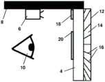
如图1a及图1b中所示,头戴式增强现实系统2具有波导4及投影机6,其中,投影机6布置成将光提供至波导4。头戴式增强现实系统2具有头部支架8,波导4和投影机6固定于头部支架8上。头部支架8还构造成将波导4间隔在相对于用户的假想眼睛位置10的位置处。在一个布置中,头部支架8是类似于一副眼镜的框架的框架。在另一布置中,头部支架8是头盔。本领域技术人员将容易想到除了波导外的替代光学部件,例如在头戴式增强现实系统中使用的棱镜(参见图3)。As shown in FIGS. 1 a and 1 b , the head-mounted augmented reality system 2 has a
杂散光抑制层12定位于波导4的外表面上。杂散光抑制层12包括透明基底材料14及多个板条16。多个板条16或遮光体以多个角度布置于杂散光抑制层12中。在一个布置中,多个板条16由不透明遮光材料制成。另外,多个板条16可以将光反射远离波导4。在图1中描绘的实施方式中,仅存在少量板条16,但在其他实施方式中,可以提供较大量板条16。The stray
输入衍射光学元件18定位在波导4上,以接收来自投影机6的光并且将光耦合至波导4中。输出衍射光学元件20定位在波导4上,以将波导4内的光自波导4朝向用户耦出。以这种方式,来自投影机6的光可以增强用户对外部世界的视野,他们也可以通过透明波导4感知外部世界。An input diffractive
头部支架8构造成将波导4及杂散抑制层12定位在距用户的假想眼睛位置10的期望距离处,使得用户无法聚焦于多个板条16上。用户的假想眼睛位置10是一般用户的眼睛可能定位的空间位置。已预期用户将具有不同形状的头部,并且在任何个别情况中,用户的眼睛的实际位置可能稍微不同于用户的假想眼睛位置10。人眼无法容易聚焦于小于6.5cm远的物体。因此,头戴式增强现实系统可以将杂散抑制层12定位在距用户的假想眼睛位置10小于6.5cm远的距离处。例如,头部支架8构造成将杂散光抑制层12间隔在远离用户的假想眼睛位置102cm至3cm的笔直水平距离处。因此,波导4及杂散光抑制层12意在用于“近眼”应用。The
头部支架8构造成在配戴于用户的头上时从用户的视角限定竖直方向。当用户的视线在水平面上时,多个板条16布置成抑制竖直方向上的杂散光。例如,各板条可以相对于竖直方向水平定位,使得可以阻挡来自头顶或用户的视线下方的杂散光。The
杂散光抑制层12定位于波导4的外表面上以防止来自外部环境的不期望的高角度杂散光到达波导4。在一个示例中,杂散光抑制层12是可以粘贴至波导4的外表面上的粘合膜。或者,杂散光抑制层12和波导4可以作为单个部件存在,其中,多个板条16布置成朝向该单个部件的外表面。Stray
多个板条16中的每个板条具有轴线,并且轴以多个角度布置。板条16布置成使得轴中的每个轴被引导朝向用户的假想眼睛位置10。以这种方式,在轮廓上向用户的假想眼睛位置呈现板条的薄边缘。板条16的布置意味着用户几乎察觉不到这些边缘。例如,板条可以具有薄立方体形状,其中,较大矩形截面阻挡杂散光并且佩戴该系统的用户仅可以看见立方体板条的边缘或较小矩形截面。本领域技术人员将容易想到板条的替代形状。Each of the plurality of
各板条的尺寸也可以选择成最小化对用户的可见度。例如,各板条可以为10微米厚且200微米长。另外,多个板条16布置在波导4内使得各板条之间存在具有最小尺寸的间隙,以容许来自外部环境的期望的光穿过杂散光抑制层12而至波导4中。例如,各板条之间的最小间隙距离可以为115微米,以确保足够的外部光通过杂散光抑制层12。The size of each slat can also be selected to minimize visibility to the user. For example, each slat can be 10 microns thick and 200 microns long. Additionally, the plurality of
在使用中,用户将使用头部支架8来将头戴式增强现实系统2定位于他们的头上。用户的眼睛将定位成靠近头部支架所限定的用户的假想眼睛位置10。板条16将定向成使轴大致朝向用户的眼睛位置定向。板条16定向成且定位成使得它们可以抑制高仰角的光但可以继续容许用户正常观看。板条16的布置有利地减少诸如彩虹的不期望的光学效应。In use, the user will use the
图2是头戴式增强现实系统102的实施方式,其中,头部支架108包括框架,波导104、投影机106和透明基板122安装在该框架上。头部支架108构造成将波导104间隔在相对于用户的假想眼睛位置110的位置处。透明基板122是与波导104分离的部件。杂散光抑制层112粘合至透明基板122的表面上。杂散光抑制层112包括透明基底材料114及多个板条116。多个板条116以多个角度布置在杂散光抑制层112中。FIG. 2 is an embodiment of a head mounted
输入衍射光学元件118定位于波导104上以接收来自投影机106的光并且将光耦合至波导104中。输出衍射光学元件120定位于波导104上以将波导104内的光自波导104朝向用户耦出。Input diffractive
透明基板122可以用作屏障以保护波导104使其免受物理损坏,并且/或用作杂散光抑制层112可以粘合于其上的表面。在一个布置中,头部支架108是具有作为透明基板122的遮阳板结构的头盔。The
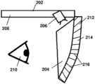
图3是头戴式增强现实系统202的另一实施方式,其中,头部支架208包括框架,棱镜204及投影机206安装在该框架上。头部支架208构造成将棱镜204间隔在相对于用户的假想眼睛位置210的位置处。杂散光抑制层212定位于棱镜204的外表面上以防止来自外部环境的不期望的高角度杂散光到达棱镜204。杂散光抑制层212包括透明基底材料214和多个板条216。多个板条216以多个角度布置于杂散光抑制层212中。FIG. 3 is another embodiment of a head-mounted
在一个示例中,杂散光抑制层212是可以粘贴至棱镜204的外表面上的粘合膜。或者,杂散光抑制层212和棱镜204可以作为单个部件存在,其中,多个板条216布置成朝向该单个部件的外表面。In one example, stray
如图4中展示,抬头显示增强现实系统302具有波导304及投影机306,其中,投影机306布置成将光提供至波导304。波导304构造成限定用户的假想眼睛位置308。As shown in FIG. 4 , the heads-up display augmented
杂散光抑制层310定位于波导304的外表面上。杂散光抑制层310包括透明基底材料312和多个板条314。多个板条314或遮光体以多个角度布置于杂散光抑制层310中。在一个布置中,多个板条314由不透明遮光材料制成。另外,多个板条314可以将光反射远离波导304。Stray
在图4中描绘的实施方式中,仅存在少量板条314,但在其他实施方式中,可以提供较大量板条314。各板条的薄边缘的尺寸(在轮廓上向用户的假想眼睛位置呈现)及板条的数量选择成使得用户几乎察觉不到该多个板条314。In the embodiment depicted in Figure 4, only a small number of
输入衍射光学元件316定位于波导304上以接收来自投影机306的光并且将光耦合至波导304中。输出衍射光学元件318定位于波导304上以将波导304内的光自波导304朝向用户耦出。以这种方式,来自投影机306的光可以增强用户对外部世界的视野,他们也可以通过透明波导304感知外部世界。Input diffractive
图5是在从用户的假想眼睛位置在假想前视方向上的杂散光抑制层412的另一实施方式。杂散光抑制层412包括透明基底材料414和多个板条416。多个板条416或遮光体以多个角度布置于杂散光抑制层412中。FIG. 5 is another embodiment of a stray light suppression layer 412 in an imaginary forward looking direction from the user's imaginary eye position. Stray light suppression layer 412 includes transparent base material 414 and a plurality of slats 416 . A plurality of slats 416 or light shields are arranged in the stray light suppression layer 412 at various angles.
多个板条416中的每个板条具有轴线,并且轴以多个角度布置。多个角度是从用户的假想眼睛位置判定的多个立体角度,使得板条416布置成使得轴中的每个轴被引导朝向用户的假想眼睛位置。以这种方式,在轮廓上向用户的假想眼睛位置呈现板条的薄边缘。板条416的布置意味着用户几乎察觉不到这些边缘。Each of the plurality of slats 416 has an axis, and the axis is arranged at various angles. The angles are solid angles determined from the user's imaginary eye position, such that the slats 416 are arranged such that each of the axes is directed toward the user's imaginary eye position. In this way, the thin edges of the slats are presented in profile to the user's imaginary eye position. The arrangement of the slats 416 means that these edges are barely noticeable to the user.
各板条具有平截头体或圆锥体的部段的形状,使得板条在二维或正面视图中呈现圆形。多个板条416是透明基底材料414中的一组嵌套圆锥体,并且在面向用户的视线时看似一组同心圆。本领域技术人员将容易想到板条的替代形状,诸如丸状、棱锥体或椭圆形板条。Each slat has the shape of a segment of a frustum or cone, so that the slats appear circular in two-dimensional or frontal view. The plurality of slats 416 are a set of nested cones in the transparent base material 414 and appear to be a set of concentric circles when facing the user's line of sight. Alternative shapes for the slats will readily occur to those skilled in the art, such as pellets, pyramids or oval slats.
本领域技术人员将容易想到在增强现实系统中使用的杂散光抑制层的替代构型。Alternative configurations of stray light suppression layers for use in augmented reality systems will readily occur to those skilled in the art.
Claims (17)
Applications Claiming Priority (3)
| Application Number | Priority Date | Filing Date | Title |
|---|---|---|---|
| GB1708963.2 | 2017-06-06 | ||
| GBGB1708963.2AGB201708963D0 (en) | 2017-06-06 | 2017-06-06 | Head-mounted augmented reality system |
| PCT/GB2018/051406WO2018224802A1 (en) | 2017-06-06 | 2018-05-23 | Augmented reality system |
Publications (2)
| Publication Number | Publication Date |
|---|---|
| CN110753874Atrue CN110753874A (en) | 2020-02-04 |
| CN110753874B CN110753874B (en) | 2022-03-08 |
Family
ID=59349965
Family Applications (1)
| Application Number | Title | Priority Date | Filing Date |
|---|---|---|---|
| CN201880037553.0AActiveCN110753874B (en) | 2017-06-06 | 2018-05-23 | Augmented reality system |
Country Status (6)
| Country | Link |
|---|---|
| US (1) | US11513351B2 (en) |
| EP (1) | EP3635471B1 (en) |
| CN (1) | CN110753874B (en) |
| GB (1) | GB201708963D0 (en) |
| TW (1) | TWI750380B (en) |
| WO (1) | WO2018224802A1 (en) |
Cited By (1)
| Publication number | Priority date | Publication date | Assignee | Title |
|---|---|---|---|---|
| EP4127815A4 (en)* | 2020-03-23 | 2023-09-20 | Lumus Ltd. | Optical devices for mitigating ghost images |
Families Citing this family (22)
| Publication number | Priority date | Publication date | Assignee | Title |
|---|---|---|---|---|
| GB201708963D0 (en) | 2017-06-06 | 2017-07-19 | Wave Optics Ltd | Head-mounted augmented reality system |
| CN112601993A (en) | 2018-08-26 | 2021-04-02 | 鲁姆斯有限公司 | Reflection suppression in near-eye displays |
| US11067811B2 (en) | 2019-01-11 | 2021-07-20 | Facebook Technologies, Llc | Volume bragg gratings for near-eye waveguide display |
| IL264551B2 (en)* | 2019-01-29 | 2024-09-01 | Oorym Optics Ltd | Highly efficient compact head-mounted display system having small input aperture |
| GB201903037D0 (en) | 2019-03-07 | 2019-04-24 | Wave Optics Ltd | Display for augmented realityor virtual reality |
| TWI845670B (en) | 2019-05-06 | 2024-06-21 | 以色列商魯姆斯有限公司 | Transparent lightguide for viewing a scene and a near-eye display |
| US10884241B2 (en)* | 2019-06-07 | 2021-01-05 | Facebook Technologies, Llc | Optical element for reducing stray infrared light |
| US20210055551A1 (en)* | 2019-08-23 | 2021-02-25 | Facebook Technologies, Llc | Dispersion compensation in volume bragg grating-based waveguide display |
| JP7660113B2 (en) | 2019-10-17 | 2025-04-10 | マジック リープ, インコーポレイテッド | Attenuation of Light Transmittance Artifacts in Wearable Displays |
| KR20210064684A (en) | 2019-11-26 | 2021-06-03 | 삼성전자주식회사 | Light shielding film for hud and hud system for vehicle |
| US11662586B2 (en) | 2020-03-06 | 2023-05-30 | Magic Leap, Inc. | Angularly selective attenuation of light transmission artifacts in wearable displays |
| TWI718054B (en) | 2020-04-23 | 2021-02-01 | 宏碁股份有限公司 | Optical device combining spectacle function with augmented reality function and augmented reality device |
| KR20230024409A (en) | 2020-06-25 | 2023-02-20 | 매직 립, 인코포레이티드 | Tunable Attenuation of Light Transmission Artifacts in Wearable Displays |
| JP7665364B2 (en)* | 2020-09-10 | 2025-04-21 | キヤノン株式会社 | Angle-selective transmission element and display device |
| WO2022054447A1 (en)* | 2020-09-10 | 2022-03-17 | キヤノン株式会社 | Angle selection type transmission element and display device |
| WO2022105969A1 (en)* | 2020-11-17 | 2022-05-27 | Continental Automotive Gmbh | Apparatus for generating a virtual image, comprising an adjustment mechanism for antireflective lamellae |
| CN113009697A (en)* | 2021-03-17 | 2021-06-22 | Oppo广东移动通信有限公司 | Near-to-eye display optical system and near-to-eye display device |
| JP7625456B2 (en)* | 2021-03-19 | 2025-02-03 | キヤノン株式会社 | Optical and display devices |
| CN115145028A (en)* | 2021-03-31 | 2022-10-04 | 华为技术有限公司 | Augmented reality device and display method thereof |
| GB2617643B (en)* | 2022-08-31 | 2024-10-23 | Envisics Ltd | Display system and light control element therefor |
| WO2025079280A1 (en)* | 2023-10-11 | 2025-04-17 | アルディーテック株式会社 | Pan-focus glasses, xr glasses, and contact lenses with collimating function |
| JP7549932B1 (en) | 2024-01-11 | 2024-09-12 | アルディーテック株式会社 | Pan focus glasses and XR glasses |
Citations (6)
| Publication number | Priority date | Publication date | Assignee | Title |
|---|---|---|---|---|
| US4711512A (en)* | 1985-07-12 | 1987-12-08 | Environmental Research Institute Of Michigan | Compact head-up display |
| WO2013128615A1 (en)* | 2012-03-01 | 2013-09-06 | パイオニア株式会社 | Head-up display |
| CN103429143A (en)* | 2011-03-18 | 2013-12-04 | Smi创新传感技术有限公司 | Optical measuring device and system |
| CN103823304A (en)* | 2013-12-31 | 2014-05-28 | 苏州卫生职业技术学院 | Low-eyesight glasses |
| US20140168260A1 (en)* | 2012-12-13 | 2014-06-19 | Paul M. O'Brien | Waveguide spacers within an ned device |
| US9644816B1 (en)* | 2015-01-12 | 2017-05-09 | Rockwell Collins, Inc. | Tailored stray light control for display applications |
Family Cites Families (20)
| Publication number | Priority date | Publication date | Assignee | Title |
|---|---|---|---|---|
| US1089539A (en)* | 1913-11-07 | 1914-03-10 | Theodore P Driver | Light-shield. |
| US1683505A (en)* | 1927-03-05 | 1928-09-04 | Golfada Company | Golf blinder |
| US2232455A (en)* | 1936-10-20 | 1941-02-18 | Hebrard Leon | Spectacles or goggles |
| US2114658A (en)* | 1937-06-03 | 1938-04-19 | Henry L Noffsinger | Sun goggles |
| US2824308A (en)* | 1954-04-29 | 1958-02-25 | Borg Warner | Louvered screen eyeglass |
| US3756703A (en)* | 1971-12-29 | 1973-09-04 | R Nelson | Sunglasses containing embedded louver means |
| US5016950A (en)* | 1988-07-05 | 1991-05-21 | Hughes Aircraft Company | Full-color zero-order suppressed diffraction optics diffusing screen/louver filter laminate |
| US4869584A (en)* | 1988-10-11 | 1989-09-26 | Dion Peter R | Louvered sunglasses |
| US4953231A (en)* | 1989-07-19 | 1990-09-04 | Burnett David W | Shade attachment for eyeglasses |
| JP6244888B2 (en) | 2013-09-03 | 2017-12-13 | セイコーエプソン株式会社 | Virtual image display device |
| US9733475B1 (en)* | 2014-09-08 | 2017-08-15 | Rockwell Collins, Inc. | Curved waveguide combiner for head-mounted and helmet-mounted displays (HMDS), a collimated virtual window, or a head up display (HUD) |
| US10088683B2 (en) | 2014-10-24 | 2018-10-02 | Tapuyihai (Shanghai) Intelligent Technology Co., Ltd. | Head worn displaying device employing mobile phone |
| JP6535456B2 (en) | 2014-11-10 | 2019-06-26 | 株式会社日立エルジーデータストレージ | Image projection apparatus and head mounted display |
| US10234686B2 (en)* | 2015-11-16 | 2019-03-19 | Microsoft Technology Licensing, Llc | Rainbow removal in near-eye display using polarization-sensitive grating |
| US20170315356A1 (en)* | 2016-04-28 | 2017-11-02 | Jani Kari Tapio Tervo | Waveguides of near-eye display devices for suppressing ghost images |
| WO2018081305A1 (en)* | 2016-10-26 | 2018-05-03 | Magic Leap, Inc. | Outcoupling grating for augmented reality system |
| US11163099B2 (en)* | 2016-11-22 | 2021-11-02 | 3M Innovative Properties Company | Spectrally selective light control film |
| GB201708963D0 (en) | 2017-06-06 | 2017-07-19 | Wave Optics Ltd | Head-mounted augmented reality system |
| US10390001B2 (en)* | 2017-06-27 | 2019-08-20 | He Li ZHOU | Rear view vision system for a vehicle |
| US10859834B2 (en)* | 2017-07-03 | 2020-12-08 | Holovisions | Space-efficient optical structures for wide field-of-view augmented reality (AR) eyewear |
- 2017
- 2017-06-06GBGBGB1708963.2Apatent/GB201708963D0/ennot_activeCeased
- 2018
- 2018-05-23EPEP18728711.5Apatent/EP3635471B1/enactiveActive
- 2018-05-23CNCN201880037553.0Apatent/CN110753874B/enactiveActive
- 2018-05-23WOPCT/GB2018/051406patent/WO2018224802A1/ennot_activeCeased
- 2018-05-23USUS16/619,888patent/US11513351B2/enactiveActive
- 2018-06-05TWTW107119245Apatent/TWI750380B/enactive
Patent Citations (6)
| Publication number | Priority date | Publication date | Assignee | Title |
|---|---|---|---|---|
| US4711512A (en)* | 1985-07-12 | 1987-12-08 | Environmental Research Institute Of Michigan | Compact head-up display |
| CN103429143A (en)* | 2011-03-18 | 2013-12-04 | Smi创新传感技术有限公司 | Optical measuring device and system |
| WO2013128615A1 (en)* | 2012-03-01 | 2013-09-06 | パイオニア株式会社 | Head-up display |
| US20140168260A1 (en)* | 2012-12-13 | 2014-06-19 | Paul M. O'Brien | Waveguide spacers within an ned device |
| CN103823304A (en)* | 2013-12-31 | 2014-05-28 | 苏州卫生职业技术学院 | Low-eyesight glasses |
| US9644816B1 (en)* | 2015-01-12 | 2017-05-09 | Rockwell Collins, Inc. | Tailored stray light control for display applications |
Cited By (1)
| Publication number | Priority date | Publication date | Assignee | Title |
|---|---|---|---|---|
| EP4127815A4 (en)* | 2020-03-23 | 2023-09-20 | Lumus Ltd. | Optical devices for mitigating ghost images |
Also Published As
| Publication number | Publication date |
|---|---|
| EP3635471B1 (en) | 2021-08-25 |
| WO2018224802A1 (en) | 2018-12-13 |
| US11513351B2 (en) | 2022-11-29 |
| US20200103650A1 (en) | 2020-04-02 |
| TWI750380B (en) | 2021-12-21 |
| TW201903473A (en) | 2019-01-16 |
| CN110753874B (en) | 2022-03-08 |
| EP3635471A1 (en) | 2020-04-15 |
| GB201708963D0 (en) | 2017-07-19 |
Similar Documents
| Publication | Publication Date | Title |
|---|---|---|
| TWI750380B (en) | Augmented reality system | |
| US8743464B1 (en) | Waveguide with embedded mirrors | |
| US10061126B2 (en) | Optical device | |
| CN102667912B (en) | Head-mounted display device | |
| US7158095B2 (en) | Visual display system for displaying virtual images onto a field of vision | |
| US9551872B1 (en) | Spatially multiplexed lens for head mounted display | |
| ES2386724T3 (en) | High head display | |
| CN103718083B (en) | Head-mounted display and eyepiece for head-mounted display | |
| US9442291B1 (en) | Segmented diffractive optical elements for a head wearable display | |
| JP6697455B2 (en) | Head-mounted viewing system including crossed optics | |
| WO2009066408A4 (en) | Display device, display method and head-up display | |
| US20020186179A1 (en) | Optical display device | |
| CN106662745A (en) | Compact architecture for near-to-eye display system | |
| JP7025439B2 (en) | Split exit pupil head-up display system and method | |
| CN104956253A (en) | See-through near-to-eye display with eye prescription | |
| EP2246728A1 (en) | Head mounted display | |
| KR102780284B1 (en) | Display device | |
| CN107843985A (en) | Augmented reality HUD system and method | |
| JP2022554052A (en) | Head-up display without ghost images | |
| US10409077B2 (en) | Distributed aperture head up display (HUD) | |
| US12072535B2 (en) | Display device | |
| CN209281075U (en) | Augmented reality device | |
| WO2021197060A1 (en) | Head-mounted display device | |
| HK40027066A (en) | Augmented reality system | |
| HK40027066B (en) | Augmented reality system |
Legal Events
| Date | Code | Title | Description |
|---|---|---|---|
| PB01 | Publication | ||
| PB01 | Publication | ||
| SE01 | Entry into force of request for substantive examination | ||
| SE01 | Entry into force of request for substantive examination | ||
| GR01 | Patent grant | ||
| GR01 | Patent grant | ||
| TR01 | Transfer of patent right | ||
| TR01 | Transfer of patent right | Effective date of registration:20231128 Address after:California, USA Patentee after:SNAP Inc. Address before:Abbington, Oxfordshire, UK Patentee before:WAVE OPTICS LTD. |