CN110753645A - Cleaning device for cleaning a transparent element of an optical or optoelectronic device - Google Patents
Cleaning device for cleaning a transparent element of an optical or optoelectronic deviceDownload PDFInfo
- Publication number
- CN110753645A CN110753645ACN201880038681.7ACN201880038681ACN110753645ACN 110753645 ACN110753645 ACN 110753645ACN 201880038681 ACN201880038681 ACN 201880038681ACN 110753645 ACN110753645 ACN 110753645A
- Authority
- CN
- China
- Prior art keywords
- cleaning
- annular channel
- housing
- optical
- cleaning agent
- Prior art date
- Legal status (The legal status is an assumption and is not a legal conclusion. Google has not performed a legal analysis and makes no representation as to the accuracy of the status listed.)
- Pending
Links
- 238000004140cleaningMethods0.000titleclaimsabstractdescription43
- 230000003287optical effectEffects0.000titleclaimsabstractdescription38
- 230000005693optoelectronicsEffects0.000titleclaimsabstractdescription22
- 238000010438heat treatmentMethods0.000claimsabstractdescription44
- 239000012459cleaning agentSubstances0.000claimsabstractdescription31
- 239000007921spraySubstances0.000claimsabstractdescription4
- 239000012530fluidSubstances0.000claimsabstractdescription3
- 238000007689inspectionMethods0.000claimsdescription6
- 238000001514detection methodMethods0.000claimsdescription4
- 239000000463materialSubstances0.000claimsdescription4
- 239000007769metal materialSubstances0.000claimsdescription4
- 238000005266castingMethods0.000description4
- 239000003599detergentSubstances0.000description3
- 239000007788liquidSubstances0.000description3
- 230000000694effectsEffects0.000description2
- 230000008014freezingEffects0.000description2
- 238000007710freezingMethods0.000description2
- 238000009434installationMethods0.000description2
- 230000006978adaptationEffects0.000description1
- 230000002411adverseEffects0.000description1
- 230000005494condensationEffects0.000description1
- 238000009833condensationMethods0.000description1
- 238000011109contaminationMethods0.000description1
- 238000005260corrosionMethods0.000description1
- 230000007797corrosionEffects0.000description1
- 230000001419dependent effectEffects0.000description1
- 230000007613environmental effectEffects0.000description1
- 239000007789gasSubstances0.000description1
- 230000017525heat dissipationEffects0.000description1
- 238000001746injection mouldingMethods0.000description1
- 238000000034methodMethods0.000description1
- 239000000203mixtureSubstances0.000description1
- 238000007789sealingMethods0.000description1
- XLYOFNOQVPJJNP-UHFFFAOYSA-NwaterSubstancesOXLYOFNOQVPJJNP-UHFFFAOYSA-N0.000description1
Images


Classifications
- B—PERFORMING OPERATIONS; TRANSPORTING
- B60—VEHICLES IN GENERAL
- B60S—SERVICING, CLEANING, REPAIRING, SUPPORTING, LIFTING, OR MANOEUVRING OF VEHICLES, NOT OTHERWISE PROVIDED FOR
- B60S1/00—Cleaning of vehicles
- B60S1/02—Cleaning windscreens, windows or optical devices
- B60S1/56—Cleaning windscreens, windows or optical devices specially adapted for cleaning other parts or devices than front windows or windscreens
- G—PHYSICS
- G02—OPTICS
- G02B—OPTICAL ELEMENTS, SYSTEMS OR APPARATUS
- G02B27/00—Optical systems or apparatus not provided for by any of the groups G02B1/00 - G02B26/00, G02B30/00
- G02B27/0006—Optical systems or apparatus not provided for by any of the groups G02B1/00 - G02B26/00, G02B30/00 with means to keep optical surfaces clean, e.g. by preventing or removing dirt, stains, contamination, condensation
- G—PHYSICS
- G02—OPTICS
- G02B—OPTICAL ELEMENTS, SYSTEMS OR APPARATUS
- G02B7/00—Mountings, adjusting means, or light-tight connections, for optical elements
- G02B7/18—Mountings, adjusting means, or light-tight connections, for optical elements for prisms; for mirrors
- G02B7/181—Mountings, adjusting means, or light-tight connections, for optical elements for prisms; for mirrors with means for compensating for changes in temperature or for controlling the temperature; thermal stabilisation
- G02B7/1815—Mountings, adjusting means, or light-tight connections, for optical elements for prisms; for mirrors with means for compensating for changes in temperature or for controlling the temperature; thermal stabilisation with cooling or heating systems
- B—PERFORMING OPERATIONS; TRANSPORTING
- B60—VEHICLES IN GENERAL
- B60R—VEHICLES, VEHICLE FITTINGS, OR VEHICLE PARTS, NOT OTHERWISE PROVIDED FOR
- B60R11/00—Arrangements for holding or mounting articles, not otherwise provided for
- B60R11/04—Mounting of cameras operative during drive; Arrangement of controls thereof relative to the vehicle
- B—PERFORMING OPERATIONS; TRANSPORTING
- B60—VEHICLES IN GENERAL
- B60R—VEHICLES, VEHICLE FITTINGS, OR VEHICLE PARTS, NOT OTHERWISE PROVIDED FOR
- B60R11/00—Arrangements for holding or mounting articles, not otherwise provided for
- B60R2011/0001—Arrangements for holding or mounting articles, not otherwise provided for characterised by position
- B60R2011/004—Arrangements for holding or mounting articles, not otherwise provided for characterised by position outside the vehicle
- B—PERFORMING OPERATIONS; TRANSPORTING
- B60—VEHICLES IN GENERAL
- B60R—VEHICLES, VEHICLE FITTINGS, OR VEHICLE PARTS, NOT OTHERWISE PROVIDED FOR
- B60R2300/00—Details of viewing arrangements using cameras and displays, specially adapted for use in a vehicle
- B60R2300/10—Details of viewing arrangements using cameras and displays, specially adapted for use in a vehicle characterised by the type of camera system used
- B—PERFORMING OPERATIONS; TRANSPORTING
- B60—VEHICLES IN GENERAL
- B60S—SERVICING, CLEANING, REPAIRING, SUPPORTING, LIFTING, OR MANOEUVRING OF VEHICLES, NOT OTHERWISE PROVIDED FOR
- B60S1/00—Cleaning of vehicles
- B60S1/02—Cleaning windscreens, windows or optical devices
- B60S1/04—Wipers or the like, e.g. scrapers
- B60S1/06—Wipers or the like, e.g. scrapers characterised by the drive
- B60S1/08—Wipers or the like, e.g. scrapers characterised by the drive electrically driven
- B60S1/0818—Wipers or the like, e.g. scrapers characterised by the drive electrically driven including control systems responsive to external conditions, e.g. by detection of moisture, dirt or the like
- B60S1/0822—Wipers or the like, e.g. scrapers characterised by the drive electrically driven including control systems responsive to external conditions, e.g. by detection of moisture, dirt or the like characterized by the arrangement or type of detection means
- B60S1/0833—Optical rain sensor
- B60S1/0844—Optical rain sensor including a camera
- B60S1/0848—Cleaning devices for cameras on vehicle
- B—PERFORMING OPERATIONS; TRANSPORTING
- B60—VEHICLES IN GENERAL
- B60S—SERVICING, CLEANING, REPAIRING, SUPPORTING, LIFTING, OR MANOEUVRING OF VEHICLES, NOT OTHERWISE PROVIDED FOR
- B60S1/00—Cleaning of vehicles
- B60S1/02—Cleaning windscreens, windows or optical devices
- B60S1/46—Cleaning windscreens, windows or optical devices using liquid; Windscreen washers
- B60S1/48—Liquid supply therefor
- B60S1/487—Liquid supply therefor the liquid being heated
- B60S1/488—Liquid supply therefor the liquid being heated electrically
- B—PERFORMING OPERATIONS; TRANSPORTING
- B60—VEHICLES IN GENERAL
- B60S—SERVICING, CLEANING, REPAIRING, SUPPORTING, LIFTING, OR MANOEUVRING OF VEHICLES, NOT OTHERWISE PROVIDED FOR
- B60S1/00—Cleaning of vehicles
- B60S1/02—Cleaning windscreens, windows or optical devices
- B60S1/46—Cleaning windscreens, windows or optical devices using liquid; Windscreen washers
- B60S1/48—Liquid supply therefor
- B60S1/52—Arrangement of nozzles; Liquid spreading means
- H—ELECTRICITY
- H04—ELECTRIC COMMUNICATION TECHNIQUE
- H04N—PICTORIAL COMMUNICATION, e.g. TELEVISION
- H04N23/00—Cameras or camera modules comprising electronic image sensors; Control thereof
- H04N23/50—Constructional details
- H04N23/51—Housings
Landscapes
- Physics & Mathematics (AREA)
- Engineering & Computer Science (AREA)
- General Physics & Mathematics (AREA)
- Optics & Photonics (AREA)
- Mechanical Engineering (AREA)
- Water Supply & Treatment (AREA)
- Cleaning By Liquid Or Steam (AREA)
- Studio Devices (AREA)
- Cleaning In General (AREA)
Abstract
Translated fromChinese
Description
Translated fromChinese技术领域technical field
本发明涉及一种用于清洁光学或光电设备、特别是摄像机的透明元件的清洁设备,以及一种用于布置在车辆中的光学检测设备,该光学检测设备包括具有清洁设备的上述光学或光电设备,本发明还涉及一种安装有上述清洁设备或光学检测设备的车辆。The invention relates to a cleaning device for cleaning optical or optoelectronic devices, in particular transparent elements of cameras, and to an optical inspection device for arrangement in a vehicle, which optical inspection device comprises the above-mentioned optical or optoelectronic device with a cleaning device device, the present invention also relates to a vehicle equipped with the above cleaning device or optical detection device.
背景技术Background technique
在机动车辆中,如今越来越多地安装具有传感器的辅助系统,其在驾驶车辆时为车辆用户提供辅助,同时在任何时候可靠地检测和监控车辆的周围环境。为此,这种辅助系统包括光学或光电设备,例如摄像机、基于激光或红外的传感器。这种设备具有透明元件,例如镜头或盖,该设备根据应用情况允许光无限制地透射或在限制的特定波长范围内透射。这种透明元件通常向外凸出或拱曲地形成,以允许例如为诸如所谓的“鱼眼”摄像机镜头之类的摄像机实现特别宽的检测范围。此外,这种透明元件由于功能决定而被布置在车辆的外部区域中,并且因此全年暴露于各种气候条件下的污染和外部天气影响,并且必要时必须被清洁并保持无冰,以保证其功能。在此,喷嘴在车辆中的安装位置中的空间位置也起着重要的作用,因为一方面必须注意光学或光电设备的视野尽可能不受限制,另一方面在驾驶操作中必须考虑特定条件,例如靠近表面的气流会显著影响清洁剂的喷射和流动方向。In motor vehicles, assistance systems with sensors are increasingly being installed today, which assist the vehicle user when driving the vehicle and at the same time reliably detect and monitor the vehicle's surroundings at all times. To this end, such auxiliary systems include optical or optoelectronic devices, such as cameras, laser- or infrared-based sensors. This device has a transparent element, such as a lens or a cover, which, depending on the application, allows light to be transmitted unrestrictedly or within a restricted specific wavelength range. Such transparent elements are usually formed to be convex or curved outwards to allow, for example, a particularly wide detection range for cameras such as so-called "fisheye" camera lenses. Furthermore, such transparent elements are arranged in the outer area of the vehicle due to functional decisions and are therefore exposed to pollution and external weather influences in various climatic conditions throughout the year and must be cleaned and kept ice-free if necessary in order to guarantee its function. The spatial position of the nozzle in the installation position in the vehicle also plays an important role here, since on the one hand it must be ensured that the field of view of the optical or optoelectronic device is as unrestricted as possible, and on the other hand specific conditions must be taken into account during driving maneuvers, For example, airflow close to the surface can significantly affect the spray and flow direction of the cleaning agent.
从文献DE 10 2015 217 546 B3中已知一种用于摄像机的此类清洁设备,其中,从公共的、沿周向环绕摄像机镜头的环形通道供给出口或喷嘴。由此,喷嘴仅需很少的结构成本就可以相对于摄像机的光轴以任意角度定位,因此可以有效地适应不同的应用,并且清洁设备可以在相对较低的压力下运行。A cleaning device of this type for cameras is known from
在使用光学和光电设备时,对提高效率、减少对车辆外观的不利影响以及总体技术进步的持续需求导致光学和光电设备的小型化、功耗降低并提高了效率。由此,使光学或光电设备更容易受到污染和环境的影响,因此在极端情况下用已知的清洁系统进行可靠的清洁,尤其是在低于冰点和降雪的低温下对光学或光电设备除冰会增加耗时、清洁剂消耗和运行压力。When using optical and optoelectronic devices, the continued need to improve efficiency, reduce adverse effects on vehicle appearance, and general technological advancements has resulted in miniaturization, reduced power consumption, and increased efficiency of optical and optoelectronic devices. As a result, optical or optoelectronic devices are made more susceptible to contamination and environmental influences, so that reliable cleaning is carried out in extreme cases with known cleaning systems, especially at low temperatures below freezing and snowfall. Ice increases time, detergent consumption and operating pressure.
发明内容SUMMARY OF THE INVENTION
在这种背景下,本发明的目的是提供一种改进的清洁设备,该清洁设备使得可以在所有天气条件和运行状态下增加所使用的光学或光电设备的可用性和功能保证,或者在任何时间都保持在高水平。Against this background, the object of the present invention is to provide an improved cleaning device which makes it possible to increase the availability and functional assurance of the optical or optoelectronic devices used in all weather conditions and operating states, or at any time remain at a high level.
该目的通过独立权利要求的特征实现。根据从属权利要求以及以下描述和附图得到本发明的进一步改进方案和各种实施例。This object is achieved by the features of the independent claims. Further refinements and various embodiments of the invention result from the dependent claims as well as from the following description and drawings.
本发明提出,提供至少一个用于加热环形通道和/或用于加热壳体的或清洁剂入口的紧邻环形通道的至少一个区域的导电加热元件。The present invention proposes to provide at least one electrically conductive heating element for heating the annular channel and/or for heating at least one region of the housing or of the cleaning agent inlet which adjoins the annular channel.
在此,根据优选改进方案,环形通道由壳体中的凹部形成,该凹部沿周向环绕设备的光轴并且由盖元件封闭。在此,至少一个喷嘴布置在盖元件上,在盖元件与壳体之间的接口形成为液压密封的,优选地形成为材料锁合的、特别是焊接连接的。Here, according to a preferred development, the annular channel is formed by a recess in the housing which surrounds the optical axis of the device in the circumferential direction and is closed by a cover element. Here, at least one nozzle is arranged on a cover element, the interface between the cover element and the housing being formed as a hydraulic seal, preferably as a material-bonded, in particular welded connection.
因此提供一种具有广泛适配可能性的紧凑有效的清洁设备,该清洁设备可在所有天气条件下都可靠地工作。可以特别有效地防止结冰,并且显著减少了在清洁剂内的在低温下提高了整体系统安全性的液体除冰组分的消耗。在此,清洁效果通过多个影响因素的系统确定。该系统由喷嘴数量、清洁剂的压力和量、喷射持续时间和重复次数组成。利用本发明,该系统的各个参数可以特殊地优化调节到符合相应的要求。A compact and efficient cleaning device with a wide range of adaptation possibilities is thus provided, which can work reliably in all weather conditions. Freezing can be prevented particularly effectively, and the consumption of liquid deicing components within the cleaning agent that increases overall system safety at low temperatures is significantly reduced. Here, the cleaning effect is determined by a system of several influencing factors. The system consists of the number of nozzles, the pressure and volume of the cleaning agent, the duration of the spray and the number of repetitions. With the present invention, each parameter of the system can be specially adjusted optimally to meet the corresponding requirements.
另外,所使用的光学或光电设备被间接加热,从而保持在最佳的工作温度范围内。此外,可靠地防止了露水,从而提高了光学质量。In addition, the optical or optoelectronic devices used are heated indirectly and thus remain within the optimum operating temperature range. In addition, dew is reliably prevented, thereby improving optical quality.
根据本发明的一个优选实施方式,喷嘴与盖元件一体地形成。喷嘴可以有利地在其构造、数量和位置方面几乎不受限制地可变地布置和组合。因此,可以仅通过提供可成本有利地制造的盖元件的各种变型,就可以使清洁设备经济地适配于各种应用场合和安装位置,而无需改变其它构件和部件。According to a preferred embodiment of the invention, the nozzle is formed integrally with the cover element. The nozzles can advantageously be variably arranged and combined in an almost unlimited manner with regard to their configuration, number and position. Thus, simply by providing various variants of the cover element which can be manufactured cost-effectively, the cleaning device can be economically adapted to various applications and installation positions without having to change other components and parts.
根据本发明的第一实施方式,加热元件在壳体中布置在环形通道内部,特别优选地还附加地布置在清洁剂入口中。由此,加热元件可以特别成本有利地设计成加热丝,其可以直接加热清洁剂,以及通过从环形通道向壳体中的以及向嵌入壳体中的光学或光电设备上的热传递而间接地对环境和光学或光电设备加热。同样,也可以对整个供应管线进行加热。According to a first embodiment of the invention, the heating element is arranged in the housing inside the annular channel, particularly preferably additionally in the cleaning agent inlet. As a result, the heating element can be designed particularly cost-effectively as a heating wire, which can heat the cleaning agent directly and indirectly by heat transfer from the annular channel to the housing and to the optical or optoelectronic device embedded in the housing Heating the environment and optical or optoelectronic devices. Likewise, the entire supply line can also be heated.
根据另一根据本发明的实施方式,加热元件可以由扁平的金属材料制成,特别是制成为冲弯件,并根据一个优选改进方案在壳体中直接布置在环形通道的外部,特别是被注入或以浇注材料浇注。由此可以在结构方面实现特别有效的散热,该散热另外通过较大的表面而提高。另外,还可以将壳体干燥地加热并预热,以便在不消耗清洁剂的情况下避免例如透明元件的结冰或结露。此外,有效地保护了加热元件使其免于与清洁剂直接接触,由此降低了腐蚀和短路的风险。同样,由此可以有利地根据需要将电加热元件连接部——例如插头——独立于输水管并且在壳体上的任何位置处都无需单独密封的情况下引出。According to another embodiment according to the invention, the heating element can be produced from a flat metallic material, in particular as a punched part, and according to a preferred development be arranged in the housing directly outside the annular channel, in particular by Injected or poured with casting material. As a result, a particularly effective heat dissipation can be achieved in terms of structure, which is further increased by the larger surface area. In addition, the housing can also be dry heated and preheated in order to avoid, for example, icing or condensation of transparent elements without consuming the cleaning agent. Furthermore, the heating element is effectively protected from direct contact with cleaning agents, thereby reducing the risk of corrosion and short circuits. Likewise, the electrical heating element connection, eg a plug, can advantageously be led out independently of the water supply line and without the need for a separate seal at any point on the housing, as required.
本发明还涉及一种用于布置在车辆中的光学检测设备,该光学检测设备包括摄像机,该摄像机被设计为具有根据上述实施方式之一所述的清洁设备,本发明还涉及一种车辆,在该车辆中布置有相应的光学检测设备或根据本发明的清洁设备。The invention also relates to an optical inspection device for arrangement in a vehicle, the optical inspection device comprising a camera designed with a cleaning device according to one of the above-mentioned embodiments, a vehicle, A corresponding optical detection device or a cleaning device according to the invention is arranged in the vehicle.
附图说明Description of drawings
下面根据在附图中简化示出的实施例详述本发明。在此:The invention is explained in greater detail below on the basis of an exemplary embodiment which is shown in simplified form in the drawing. here:
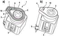
图1示出根据本发明的清洁设备的第一实施方式,该清洁设备具有以横剖面(视图a)示出的布置在其中的光学或光电设备和对应的加热元件(视图b)。Figure 1 shows a first embodiment of a cleaning device according to the invention with an optical or optoelectronic device and a corresponding heating element (view b) arranged therein, shown in cross section (view a).
图2示出根据本发明的清洁设备的第二实施方式,该清洁设备具有以横剖面(视图a)示出的布置在其中的光学或光电设备和对应的加热元件(视图b)。Figure 2 shows a second embodiment of a cleaning device according to the invention with an optical or optoelectronic device and a corresponding heating element (view b) arranged therein, shown in cross section (view a).
图3示出根据本发明的清洁设备的第三实施方式,该清洁设备具有以横剖面(视图a)示出的布置在其中的光学或光电设备和对应的加热元件(视图b)。Figure 3 shows a third embodiment of a cleaning device according to the invention with an optical or optoelectronic device and a corresponding heating element (view b) arranged therein shown in cross section (view a).
图4分别以立体图示出根据图1的、具有透明的盖元件(视图a)以及不透明的盖元件(视图b)的实施方式。FIG. 4 shows an embodiment according to FIG. 1 with a transparent cover element (view a) and an opaque cover element (view b), respectively, in a perspective view.
图5示出根据本发明的清洁设备的另一实施方式的立体图,该清洁设备具有布置在其中的光学或光电设备和仅设置在清洁剂入口中的加热元件,在此为了更好的清晰性未示出清洁剂入口的盖。5 shows a perspective view of a further embodiment of a cleaning device according to the invention with an optical or optoelectronic device arranged therein and a heating element arranged only in the cleaning agent inlet, here for better clarity The cover for the detergent inlet is not shown.
具体实施方式Detailed ways
在所有附图中,除非另有说明,否则相同或等同的元件和设备具有相同的附图标记。Throughout the drawings, the same or equivalent elements and devices have the same reference numerals unless otherwise indicated.
图1figure 1
图1示出根据本发明的清洁设备1的第一实施方式。光学或光电设备3优选可拆卸地并特别是卡锁地布置在壳体4中。Figure 1 shows a first embodiment of a cleaning device 1 according to the invention. The optical or
电接口11用于将设备3连接到此处未示出的一个或多个电源装置和电子控制单元。The
流体的、优选液体的清洁剂被未示出的输送装置——例如泵——通过管状清洁剂入口5输送到形成在壳体4中的环形通道6中。The fluid, preferably liquid, cleaning agent is conveyed through a tubular cleaning agent inlet 5 into an annular channel 6 formed in the
环形通道6主要由壳体4中的凹部形成,该凹部沿周向围绕设备3的光轴(9)。凹部由盖元件10封闭,该盖元件与壳体4密封地且抗压地/耐压地连接,在本实施例中被焊接。The annular channel 6 is mainly formed by a recess in the
喷嘴7布置在盖元件10上并且通过孔14与环形通道6液压连接。在未示出的输送装置运行时,来自环形通道6的清洁剂通过孔14被输送到喷嘴7中并且进而在那里被输送到透明元件2的表面上。The
在所示的实施例中,喷嘴7是导流板,由此喷嘴可以设计得特别扁平,以减少对设备3的光学损伤。然而,在本发明中,喷嘴也可以形成为缺口、球形插入物或集成的通道或孔。In the embodiment shown, the
在本发明中也允许液体和气体、例如压缩空气的混合物作为清洁剂。Mixtures of liquids and gases, such as compressed air, are also permissible as cleaning agents in the present invention.
在环形通道6中以及在清洁剂入口5内,布置有加热元件8。在所示的实施方式中,加热元件8被丝状地设计成环状设置的加热丝或加热电阻,该加热丝或加热电阻通过施加供给电压而变热并在此直接地加热清洁剂,以及间接地加热壳体4的相邻区域和布置在壳体中的设备3。In the annular channel 6 and in the
清洁剂入口5可以例如连接在具有位于内部的加热丝的软管上、或者连接在电动液压的连接件上,由此可以同时供给清洁剂和电能。The cleaning
图2figure 2
在图2中示出根据本发明的清洁设备1的第二实施方式。与根据图1的实施方式不同的是,加热元件8在此基本上是环形的,具有由扁平金属材料冲压制成的突出的加热元件连接部12。将加热元件插入与上述实施方式相比更深地形成的环形通道6中,并用浇注材料13进行浇注,从而与环形通道6的液体润湿部分隔离。在此,电加热元件连接部12可以在任何合适的位置处被从壳体4中引出。A second embodiment of the cleaning device 1 according to the invention is shown in FIG. 2 . In contrast to the embodiment according to FIG. 1 , the
图3
根据本发明的清洁设备1的第三实施方式具有两个喷嘴7、7',该喷嘴由环形通道6供给。原则上,在本发明中也可以使用三个或更多个喷嘴。The third embodiment of the cleaning device 1 according to the invention has two
加热元件8形成为由扁平金属材料制成的冲弯件,并且具有单独的加热元件连接部12,但是与根据图2的实施例不同的是,加热元件被直接嵌入、例如通过铸造/注塑而形成在壳体4中。为了改善从加热元件8到环形通道6的内部空间、以及壳体4的相邻区域和布置在壳体中的设备3的热传递,在该示例中加热元件8的横截面设计成L形。The
图4Figure 4
图4示出根据图1的实施方式的立体图。在此,在视图a)中盖元件被显示为透明的,以便说明环形通道6的内部结构和加热元件8的布置方式。视图b)示出处于可安装状态的清洁设备1。FIG. 4 shows a perspective view of the embodiment according to FIG. 1 . Here, the cover element is shown transparent in view a) in order to illustrate the internal structure of the annular channel 6 and the arrangement of the
图5Figure 5
在图5中示出根据本发明的清洁设备1的另一实施方式。加热元件8在此与根据图1的实施例中相同设计为丝状的,但是仅设置在清洁剂入口5内并且不再设置在环形通道6中。销状的偏转元件15用于使加热元件8偏转并且同时使其保持位置固定。为了更好的清晰性,此处未示出在技术上需要的、清洁剂入口5的后盖。Another embodiment of the cleaning device 1 according to the invention is shown in FIG. 5 . The
在不脱离本发明的情况下,所示出的实施方式的各个特征不强制性地受所示出的各个组合的限制,而是可以在本发明内彼此任意组合,以便形成其它在此未明确示出的实施方式。Without departing from the invention, the individual features of the embodiments shown are not necessarily limited to the individual combinations shown, but can be combined with one another arbitrarily within the invention in order to form other features not specified here. embodiment shown.
附图标记列表:List of reference numbers:
1 清洁设备1 Cleaning the device
2 透明元件2 transparent elements
3 光学或光电设备3 Optical or optoelectronic devices
4 壳体4 shell
5 清洁剂入口5 Detergent inlet
6 环形通道6 Ring Channels
7 喷嘴7 Nozzles
8 加热元件8 Heating elements
9 光轴9 optical axis
10 盖元件10 Cover element
11 电接口11 Electrical interface
12 加热元件连接部12 Heating element connection
13 浇注材料13 Casting material
14 孔14 holes
15 偏转元件15 Deflection element
Claims (10)
Translated fromChineseApplications Claiming Priority (3)
| Application Number | Priority Date | Filing Date | Title |
|---|---|---|---|
| DE102017206265.7 | 2017-04-12 | ||
| DE102017206265.7ADE102017206265A1 (en) | 2017-04-12 | 2017-04-12 | Cleaning device for cleaning a transparent element of an optical or optoelectronic device |
| PCT/EP2018/058692WO2018189017A1 (en) | 2017-04-12 | 2018-04-05 | Cleaning device for cleaning a transparent element of an optical or optoelectronic device |
Publications (1)
| Publication Number | Publication Date |
|---|---|
| CN110753645Atrue CN110753645A (en) | 2020-02-04 |
Family
ID=61911604
Family Applications (1)
| Application Number | Title | Priority Date | Filing Date |
|---|---|---|---|
| CN201880038681.7APendingCN110753645A (en) | 2017-04-12 | 2018-04-05 | Cleaning device for cleaning a transparent element of an optical or optoelectronic device |
Country Status (6)
| Country | Link |
|---|---|
| US (1) | US12151654B2 (en) |
| EP (1) | EP3609749B1 (en) |
| KR (1) | KR20190139246A (en) |
| CN (1) | CN110753645A (en) |
| DE (1) | DE102017206265A1 (en) |
| WO (1) | WO2018189017A1 (en) |
Families Citing this family (6)
| Publication number | Priority date | Publication date | Assignee | Title |
|---|---|---|---|---|
| DE102018210254A1 (en)* | 2018-06-22 | 2019-12-24 | Continental Automotive Gmbh | Electronically controlled hydraulic cleaning system |
| US12269436B2 (en)* | 2020-07-09 | 2025-04-08 | A. Raymond Et Cie | Bracket and modular assembly for fluid spray system |
| KR102259701B1 (en)* | 2020-10-28 | 2021-06-02 | 심을섭 | Cleaning equipment for cleaning covers used in optical devices |
| US12019460B2 (en) | 2021-06-24 | 2024-06-25 | Apple Inc. | Shared compressor |
| FR3135238A1 (en)* | 2022-05-03 | 2023-11-10 | Valeo Systèmes D’Essuyage | Device for cleaning an optical surface of a sensor, detection system and manufacturing method |
| FR3138395B1 (en)* | 2022-07-28 | 2024-11-29 | Elwedys | Air jet cleaning of an optic |
Citations (5)
| Publication number | Priority date | Publication date | Assignee | Title |
|---|---|---|---|---|
| CN102267419A (en)* | 2010-04-28 | 2011-12-07 | 株式会社电装 | Cover of vehicle optical sensor and vehicle optical sensor device |
| US20160001330A1 (en)* | 2011-03-10 | 2016-01-07 | Alan Romack | Integrated automotive system, nozzle assembly and remote control method for cleaning an image sensor's exterior or objective lens surface |
| US20160103316A1 (en)* | 2014-10-10 | 2016-04-14 | Valeo Systèmes d'Essuyage | Device for cleaning a motor vehicle driving aid camera |
| WO2016164173A1 (en)* | 2015-04-08 | 2016-10-13 | Illinois Tool Works Inc. | Camera heater for advanced driver assistance system |
| DE102015217546B3 (en)* | 2015-09-14 | 2017-03-02 | Continental Automotive Gmbh | Cleaning device for cleaning a transparent cover of a camera |
Family Cites Families (72)
| Publication number | Priority date | Publication date | Assignee | Title |
|---|---|---|---|---|
| US1792434A (en)* | 1928-05-28 | 1931-02-10 | Daniel S Lockwood | Wax and compound heating apparatus |
| US3034726A (en)* | 1958-07-21 | 1962-05-15 | Renault | Heating and atomizing device |
| DE1497581A1 (en)* | 1966-09-27 | 1969-04-03 | Siemens Ag | Device for preventing dust deposits on the lenses of optical devices |
| EP0104673B1 (en)* | 1982-09-24 | 1987-11-19 | Onofrio Rocchitelli | Heating device for the glass washing fluid of motor vehicles and the like |
| GB8321417D0 (en)* | 1983-08-09 | 1983-09-07 | M & W Exports Ltd | Screen washer |
| US4558204A (en)* | 1984-03-09 | 1985-12-10 | Ingo Bleckmann | Electric continuous flow water heater assembly for a beverage making machine |
| DE3643476A1 (en)* | 1986-12-19 | 1988-06-30 | Swf Auto Electric Gmbh | WINDOW CLEANING SYSTEM |
| DE8704903U1 (en)* | 1987-04-02 | 1987-05-27 | REHAU AG + Co, 8673 Rehau | Connector for heated hoses |
| GB2250218A (en)* | 1990-11-29 | 1992-06-03 | Engineering Research & Applic | Nozzle assembly |
| US5361990A (en)* | 1991-12-20 | 1994-11-08 | Texas Instruments Incorporated | Fuel injector heater |
| FR2698514B1 (en)* | 1992-11-20 | 1995-05-12 | Moulinex Sa | Method of manufacturing an electric water heater for a hot drink dispenser and water heater obtained by this method. |
| DE4404409A1 (en)* | 1994-02-11 | 1995-08-17 | Kammerer Gmbh M | Windscreen washer system for motor vehicles |
| JP2963843B2 (en)* | 1994-06-06 | 1999-10-18 | 株式会社ミツバ | Washer nozzle for vehicles |
| DE19514487A1 (en)* | 1994-12-01 | 1996-06-05 | Schoettli Ag | Radiator for a nozzle holder |
| US5791377A (en)* | 1996-07-08 | 1998-08-11 | Yazaki Corporation | Electrically heated conduit |
| JP3147805B2 (en)* | 1997-02-25 | 2001-03-19 | アスモ株式会社 | Washer nozzle |
| FR2763521B1 (en)* | 1997-05-23 | 1999-07-16 | Inderflex | DEVICE FOR HEATING A JET |
| US5957384A (en)* | 1997-08-26 | 1999-09-28 | Lansinger; Jere Rask | Windshield heated wiping system |
| DE19855388A1 (en)* | 1998-12-01 | 2000-06-15 | Mannesmann Vdo Ag | Heating for a component of a motor vehicle to be heated |
| GB2350552A (en)* | 1999-06-03 | 2000-12-06 | Rover Group | Heated washer assembly for motor vehicle glazing |
| DE29920259U1 (en)* | 1999-11-18 | 2000-02-03 | REHAU AG + Co., 95111 Rehau | Device for use in windscreen washer systems |
| EP1201933B1 (en)* | 2000-10-25 | 2006-03-08 | Eichenauer Heizelemente GmbH & Co.KG | Pump housing with integrated heater |
| US6442341B1 (en)* | 2000-11-27 | 2002-08-27 | Chia-Hsiung Wu | Simple-type fluid heating tube structural arrangement |
| GB2401778B (en)* | 2003-05-21 | 2006-09-06 | Rehau Ag & Co | Nozzle body for a cleaning system on a motor vehicle |
| DE03727517T1 (en)* | 2003-05-22 | 2008-04-24 | Fico Mirrors, S.A. | Image acquisition module with a heating device, with which the environment of a motor vehicle is guarded |
| DE102007005130B4 (en)* | 2007-02-01 | 2019-03-28 | Continental Automotive Gmbh | Nozzle device for cleaning a disk |
| US20090218334A1 (en)* | 2008-02-28 | 2009-09-03 | Kyie Wallace | Heated Motorcycle Gas Tank Cover |
| DE202008007392U1 (en)* | 2008-06-03 | 2009-10-29 | Voss Automotive Gmbh | Fluid line and pipe connector for guiding and heating a medium |
| KR100973708B1 (en)* | 2008-09-02 | 2010-08-04 | 콘티넨탈 오토모티브 일렉트로닉스 유한회사 | Washer liquid heating device of vehicle |
| CA2742886A1 (en)* | 2008-12-19 | 2010-06-24 | Hsuan Yao Huang | Vehicular fluid heater |
| US20140217079A1 (en)* | 2009-08-13 | 2014-08-07 | James R. Nelson | System for snow and ice removal |
| DE202009012431U1 (en)* | 2009-09-15 | 2011-02-10 | A. Raymond Et Cie S.C.S. | Connecting device for a windshield wiper system |
| CA2965953C (en)* | 2010-04-28 | 2019-08-27 | Watlow Electric Manufacturing Company | Flow through heater |
| EP2431231B1 (en)* | 2010-09-20 | 2013-01-23 | C.R.F. Società Consortile per Azioni | Rearview camera unit for motor-vehicles |
| EP2434195B1 (en)* | 2010-09-23 | 2013-03-13 | Andreas Massold | Method for temperature measurement in a vehicle |
| TWM408051U (en)* | 2011-01-04 | 2011-07-21 | Topview Optronics Corp | Defogging and defrosting device for camera protection lens |
| DE102011084865A1 (en)* | 2011-10-20 | 2013-04-25 | Ford Global Technologies, Llc | Method for manufacturing heating element of windshield wiper system nozzle for motor car, involves performing injection molding of heating element and connection cable so as to form housing portion of heating element in holder |
| US20130146577A1 (en)* | 2011-12-08 | 2013-06-13 | Continental Automotive Systems, Inc. | Vehicle mounted optical and sensor cleaning system |
| FR2984256B1 (en)* | 2011-12-19 | 2016-09-02 | Valeo Systemes Dessuyage | PLASTIC AND THERMOCONDUCTIVE COMPONENT OF A SYSTEM FOR THE SUPPLY AND / OR DISTRIBUTION OF ICE WASTE LIQUID OF A MOTOR VEHICLE |
| US9796359B2 (en) | 2012-02-23 | 2017-10-24 | The Raymond Corporation | Method and apparatus for removing and preventing lens surface contamination on a vehicle lens |
| WO2013170887A1 (en)* | 2012-05-15 | 2013-11-21 | Bleckmann Gmbh & Co. Kg | Helical dynamic flow through heater |
| KR101827005B1 (en)* | 2012-08-08 | 2018-02-07 | 현대자동차주식회사 | Washer nozzle for vehicle |
| FR3003219B1 (en)* | 2013-03-14 | 2016-11-18 | Valeo Systemes Dessuyage | DEVICE FOR DISPENSING WINDSCREEN ICE WIPER BLINK FOR MOTOR VEHICLE WIPER |
| DE102013211870B4 (en)* | 2013-06-21 | 2022-03-24 | Continental Automotive Gmbh | Washer nozzle for a windshield washer system of a motor vehicle |
| JP6379665B2 (en)* | 2013-08-12 | 2018-08-29 | 株式会社デンソー | In-vehicle optical sensor cleaning device |
| FR3013291B1 (en)* | 2013-11-21 | 2017-07-14 | Valeo Systemes Dessuyage | HYDRAULIC HEATING INTERFACE FOR A SYSTEM FOR THE SUPPLY AND / OR DISTRIBUTION OF LIQUID WASHING ICE OF MOTOR VEHICLE |
| FR3015173B1 (en)* | 2013-12-17 | 2019-04-12 | Valeo Systemes D'essuyage | WIRED HEATER ELEMENT FOR A HEATING AND TRANSPORTATION DUCT OF A GLOSSY WASTE FLUID |
| DE102014205108A1 (en)* | 2014-03-19 | 2015-09-24 | Continental Teves Ag & Co. Ohg | Washer nozzle for a windscreen washer |
| KR101592696B1 (en)* | 2014-05-23 | 2016-02-15 | 현대자동차주식회사 | Spray washer nozzle for vehicle |
| EP2949521B1 (en)* | 2014-05-27 | 2019-07-24 | Fico Transpar, S.A. | Cleaning device and system for vehicle-mounted optic surface and vehicle-mounted optic sensor with cleaning device |
| DE102014213283A1 (en)* | 2014-07-09 | 2016-01-14 | Application Solutions (Electronics and Vision) Ltd. | Camera system for a vehicle |
| EP3013116A1 (en)* | 2014-10-21 | 2016-04-27 | Bleckmann GmbH & Co. KG | Heating system component and method for producing same |
| DE112015005140T5 (en)* | 2015-01-08 | 2017-08-17 | Illinois Tool Works Inc. | Compliant heater for windshield washer nozzle |
| FR3031943B1 (en)* | 2015-01-22 | 2017-02-17 | Valeo Systemes Dessuyage | REAR VISION SYSTEM AND METHOD OF OPERATING THE SYSTEM |
| DE102015104947B4 (en)* | 2015-03-31 | 2017-10-19 | Voss Automotive Gmbh | Heated media line |
| US20170023164A1 (en)* | 2015-07-24 | 2017-01-26 | Eichenauer Heizelemente Gmbh & Co. Kg | Pipe connector and method for manufacturing a pipe connector |
| FR3040952B1 (en)* | 2015-09-14 | 2017-09-08 | Valeo Systemes Dessuyage | OPTICAL DETECTION SYSTEM FOR A MOTOR VEHICLE AND METHOD OF CLEANING THE OPTICAL OF THE OPTICAL DETECTION SYSTEM |
| FR3040950B1 (en)* | 2015-09-16 | 2017-09-08 | Valeo Systemes Dessuyage | LIQUID DRIVE ADAPTER AND MOTOR VEHICLE WIPER BLADE BRAND LIQUID DISPENSING DEVICE |
| KR101673820B1 (en)* | 2015-11-02 | 2016-11-07 | 현대자동차주식회사 | Washer nozzle for vehicle |
| DE102015015553B4 (en)* | 2015-12-03 | 2021-01-14 | A.RAYMOND et Cie. SCS | Device for guiding a fluid on a wiper arm of an automobile, wiper arm and wiper arm unit of an automobile, which in particular have such a device, and a method for producing a device for guiding a fluid on a wiper arm of an automobile |
| CH711968A1 (en)* | 2015-12-28 | 2017-06-30 | C3 Casting Competence Center Gmbh | Heater. |
| FR3046391B1 (en)* | 2016-01-06 | 2018-01-26 | Valeo Systemes D'essuyage | WASHER FLUID DISPENSING DEVICE FOR MOTOR VEHICLE WIPER BLADES AND WIPING SYSTEM |
| US10268038B2 (en)* | 2016-09-16 | 2019-04-23 | Methode Electronics, Inc. | Camera lens washing device |
| US10894275B2 (en)* | 2017-01-20 | 2021-01-19 | Magna Electronics Inc. | Vehicle camera with lens heater and washer system |
| DE102017103158B4 (en)* | 2017-02-16 | 2022-04-07 | Kautex Textron Gmbh & Co. Kg | vehicle surface cleaning device |
| US20180265049A1 (en)* | 2017-03-14 | 2018-09-20 | Ford Global Technologies, Llc | Sensor and cleaning apparatus |
| FR3065379B1 (en)* | 2017-04-25 | 2020-11-06 | Valeo Systemes Dessuyage | TELESCOPIC CLEANING DEVICE |
| US11142170B2 (en)* | 2017-06-07 | 2021-10-12 | Ford Global Technologies, Llc | Pop-up washer nozzle with defrost feature |
| US20180363945A1 (en)* | 2017-06-16 | 2018-12-20 | Ford Global Technologies, Llc | Washer fluid heating assembly and heating method |
| FR3070030B1 (en)* | 2017-08-09 | 2019-08-23 | Valeo Systemes D'essuyage | SYSTEM FOR CLEANING A GLASS VEHICLE SURFACE |
| US11086092B2 (en)* | 2017-11-03 | 2021-08-10 | Integrated Micro-Electronics Inc. | Camera lens heater |
| FR3079627B1 (en)* | 2018-03-29 | 2021-07-09 | Delphi Tech Llc | OPTICAL DEVICE FOR VEHICLES INCLUDING A HEATING ELEMENT |
- 2017
- 2017-04-12DEDE102017206265.7Apatent/DE102017206265A1/ennot_activeWithdrawn
- 2018
- 2018-04-05USUS16/604,604patent/US12151654B2/enactiveActive
- 2018-04-05EPEP18716231.8Apatent/EP3609749B1/enactiveActive
- 2018-04-05KRKR1020197032952Apatent/KR20190139246A/ennot_activeWithdrawn
- 2018-04-05WOPCT/EP2018/058692patent/WO2018189017A1/ennot_activeCeased
- 2018-04-05CNCN201880038681.7Apatent/CN110753645A/enactivePending
Patent Citations (6)
| Publication number | Priority date | Publication date | Assignee | Title |
|---|---|---|---|---|
| CN102267419A (en)* | 2010-04-28 | 2011-12-07 | 株式会社电装 | Cover of vehicle optical sensor and vehicle optical sensor device |
| US20160001330A1 (en)* | 2011-03-10 | 2016-01-07 | Alan Romack | Integrated automotive system, nozzle assembly and remote control method for cleaning an image sensor's exterior or objective lens surface |
| US20160103316A1 (en)* | 2014-10-10 | 2016-04-14 | Valeo Systèmes d'Essuyage | Device for cleaning a motor vehicle driving aid camera |
| CN105499183A (en)* | 2014-10-10 | 2016-04-20 | 法雷奥系统公司 | Device for cleaning motor vehicle driving aid camera |
| WO2016164173A1 (en)* | 2015-04-08 | 2016-10-13 | Illinois Tool Works Inc. | Camera heater for advanced driver assistance system |
| DE102015217546B3 (en)* | 2015-09-14 | 2017-03-02 | Continental Automotive Gmbh | Cleaning device for cleaning a transparent cover of a camera |
Also Published As
| Publication number | Publication date |
|---|---|
| KR20190139246A (en) | 2019-12-17 |
| WO2018189017A1 (en) | 2018-10-18 |
| EP3609749B1 (en) | 2021-03-17 |
| EP3609749A1 (en) | 2020-02-19 |
| US12151654B2 (en) | 2024-11-26 |
| US20200156597A1 (en) | 2020-05-21 |
| DE102017206265A1 (en) | 2018-10-18 |
Similar Documents
| Publication | Publication Date | Title |
|---|---|---|
| CN110753645A (en) | Cleaning device for cleaning a transparent element of an optical or optoelectronic device | |
| KR102456483B1 (en) | Cleaning device for cleaning transparent covers of optical or optoelectronic devices | |
| JP6547948B2 (en) | Foreign object adhesion preventing device and camera device provided with the same | |
| US11479214B2 (en) | LiDAR sensor | |
| US11535200B2 (en) | Vehicle surface cleaning device | |
| US20180272999A1 (en) | Optical detection system for motor vehicle and method for cleaning the lens of the optical detection system | |
| US20130146577A1 (en) | Vehicle mounted optical and sensor cleaning system | |
| CN113874641A (en) | Sealing assembly for static sealing of icing-endangered component parts | |
| JP2009507697A (en) | A planned flange to seal the fuel container opening of an automobile | |
| EP2226586B1 (en) | Heating device, in particular for motor vehicle | |
| CN110167800A (en) | Vehicle sensor cleaning device | |
| CN112912286A (en) | Heating type cleaning device | |
| CN105313841A (en) | Washer liquid heating apparatus integrated into washer liquid reservoir | |
| CN209505699U (en) | A kind of integrated form camera cleaning device and the camera cleaning system with it | |
| CN101755494B (en) | Enclosures for electrical/electronic circuits | |
| JP7053815B2 (en) | Telescopic vehicle surface cleaning device | |
| US20100119391A1 (en) | Centrifugal Pump Comprising a Spiral Housing | |
| JP6751283B2 (en) | Anti-corrosion seal for injector | |
| CN101171453A (en) | Vent filter with membrane | |
| CN118988596A (en) | Nozzle system | |
| JP4746517B2 (en) | PCV valve | |
| US9157426B2 (en) | Overheat control mechanism for electrical vacuum pumps | |
| FR3024500A1 (en) | HEATING DEVICE WITH INFRARED MICROSYSTEM TEMPERATURE SENSOR AND MOTORIZATION DEVICE EQUIPPED WITH SUCH A HEATING DEVICE | |
| KR0145964B1 (en) | Driving apparatus of an electrically driven compressor | |
| KR101776477B1 (en) | Supplying apparatus of washer liquid |
Legal Events
| Date | Code | Title | Description |
|---|---|---|---|
| PB01 | Publication | ||
| PB01 | Publication | ||
| SE01 | Entry into force of request for substantive examination | ||
| SE01 | Entry into force of request for substantive examination | ||
| TA01 | Transfer of patent application right | Effective date of registration:20230112 Address after:Hannover Applicant after:Continental Automotive Technology Co.,Ltd. Address before:Hannover Applicant before:CONTINENTAL AUTOMOTIVE GmbH | |
| TA01 | Transfer of patent application right |