CN110753519B - Clip appliers with stabilizing members - Google Patents
Clip appliers with stabilizing membersDownload PDFInfo
- Publication number
- CN110753519B CN110753519BCN201880020531.3ACN201880020531ACN110753519BCN 110753519 BCN110753519 BCN 110753519BCN 201880020531 ACN201880020531 ACN 201880020531ACN 110753519 BCN110753519 BCN 110753519B
- Authority
- CN
- China
- Prior art keywords
- jaw
- jaw member
- clip
- stabilizing
- longitudinal channel
- Prior art date
- Legal status (The legal status is an assumption and is not a legal conclusion. Google has not performed a legal analysis and makes no representation as to the accuracy of the status listed.)
- Active
Links
Images


Classifications
- A—HUMAN NECESSITIES
- A61—MEDICAL OR VETERINARY SCIENCE; HYGIENE
- A61B—DIAGNOSIS; SURGERY; IDENTIFICATION
- A61B17/00—Surgical instruments, devices or methods
- A61B17/12—Surgical instruments, devices or methods for ligaturing or otherwise compressing tubular parts of the body, e.g. blood vessels or umbilical cord
- A61B17/128—Surgical instruments, devices or methods for ligaturing or otherwise compressing tubular parts of the body, e.g. blood vessels or umbilical cord for applying or removing clamps or clips
- A61B17/1285—Surgical instruments, devices or methods for ligaturing or otherwise compressing tubular parts of the body, e.g. blood vessels or umbilical cord for applying or removing clamps or clips for minimally invasive surgery
- A—HUMAN NECESSITIES
- A61—MEDICAL OR VETERINARY SCIENCE; HYGIENE
- A61B—DIAGNOSIS; SURGERY; IDENTIFICATION
- A61B17/00—Surgical instruments, devices or methods
- A61B17/10—Surgical instruments, devices or methods for applying or removing wound clamps, e.g. containing only one clamp or staple; Wound clamp magazines
- A—HUMAN NECESSITIES
- A61—MEDICAL OR VETERINARY SCIENCE; HYGIENE
- A61B—DIAGNOSIS; SURGERY; IDENTIFICATION
- A61B17/00—Surgical instruments, devices or methods
- A61B17/08—Wound clamps or clips, i.e. not or only partly penetrating the tissue ; Devices for bringing together the edges of a wound
- A61B17/083—Clips, e.g. resilient
- A—HUMAN NECESSITIES
- A61—MEDICAL OR VETERINARY SCIENCE; HYGIENE
- A61B—DIAGNOSIS; SURGERY; IDENTIFICATION
- A61B17/00—Surgical instruments, devices or methods
- A61B17/12—Surgical instruments, devices or methods for ligaturing or otherwise compressing tubular parts of the body, e.g. blood vessels or umbilical cord
- A61B17/122—Clamps or clips, e.g. for the umbilical cord
- A61B17/1227—Spring clips
- A—HUMAN NECESSITIES
- A61—MEDICAL OR VETERINARY SCIENCE; HYGIENE
- A61B—DIAGNOSIS; SURGERY; IDENTIFICATION
- A61B17/00—Surgical instruments, devices or methods
- A61B2017/00526—Methods of manufacturing
- A—HUMAN NECESSITIES
- A61—MEDICAL OR VETERINARY SCIENCE; HYGIENE
- A61B—DIAGNOSIS; SURGERY; IDENTIFICATION
- A61B90/00—Instruments, implements or accessories specially adapted for surgery or diagnosis and not covered by any of the groups A61B1/00 - A61B50/00, e.g. for luxation treatment or for protecting wound edges
- A61B90/03—Automatic limiting or abutting means, e.g. for safety
- A61B2090/033—Abutting means, stops, e.g. abutting on tissue or skin
- A61B2090/034—Abutting means, stops, e.g. abutting on tissue or skin abutting on parts of the device itself
Landscapes
- Health & Medical Sciences (AREA)
- Surgery (AREA)
- Life Sciences & Earth Sciences (AREA)
- Heart & Thoracic Surgery (AREA)
- Nuclear Medicine, Radiotherapy & Molecular Imaging (AREA)
- Engineering & Computer Science (AREA)
- Biomedical Technology (AREA)
- Medical Informatics (AREA)
- Molecular Biology (AREA)
- Animal Behavior & Ethology (AREA)
- General Health & Medical Sciences (AREA)
- Public Health (AREA)
- Veterinary Medicine (AREA)
- Vascular Medicine (AREA)
- Reproductive Health (AREA)
- Surgical Instruments (AREA)
Abstract
Description
Translated fromChinese优先权priority
本专利申请要求申请日为2017年3月21日、申请号为62/474,544的美国临时专利申请的优先权,其全部公开内容并入本文。This patent application claims priority to U.S. Provisional Patent Application No. 62/474,544, filed March 21, 2017, the entire disclosure of which is incorporated herein.
技术领域technical field
本发明总体上涉及施夹器,更具体涉及具有稳定构件的施夹器。The present invention relates generally to clip appliers, and more particularly to clip appliers having stabilizing members.
背景技术Background technique
结扎组织(例如,血管、淋巴结、神经、输卵管和心脏组织)是许多外科手术的惯常做法。这一做法的具体方式是,用手术夹闭合血管或用手术缝线缝合血管。使用手术缝线需要复杂地操作缝针和手术缝线来形成固定血管所需的结。这样复杂的操作十分耗时且执行困难,特别是在以空间和/或可见度有限为特点的内窥镜外科手术中。相比之下,手术夹相对更快又更易于施加。据此,在内窥镜和开放性外科手术中使用手术夹展现急剧增长。Ligation of tissue (eg, blood vessels, lymph nodes, nerves, fallopian tubes, and cardiac tissue) is routine in many surgical procedures. This is done by closing the blood vessel with surgical clips or suturing the blood vessel with surgical sutures. The use of surgical sutures requires complex manipulation of the needle and surgical suture to form the knots needed to secure the blood vessel. Such complex procedures are time consuming and difficult to perform, especially in endoscopic surgery characterized by limited space and/or visibility. In contrast, surgical clips are relatively quicker and easier to apply. Accordingly, the use of surgical clips in endoscopic and open surgical procedures exhibits a sharp growth.
发明内容Contents of the invention
本发明人认识到需要改进施夹器和/或手术夹的一个或多个特征,例如手术夹在施夹器中的稳定性。通常由具有一对相对钳口构件的施夹器来施加手术夹。目前可购得的施夹器通常以相对钳口构件与手术夹的夹脚构件之间的两个接触点固定手术夹。两个接触点无法为手术夹提供足够的稳定性,手术夹可能在外科手术过程中不利地相对于施夹器移动或甚至从钳口构件间脱落。本发明的方法和系统旨在缓解或解决上述一个或多个问题和/或现有技术中的其他问题。The present inventors have recognized a need to improve one or more features of clip appliers and/or surgical clips, such as the stability of surgical clips in the clip applier. Surgical clips are typically applied by a clip applier having a pair of opposing jaw members. Currently available clip appliers typically secure the clip with two points of contact between the opposing jaw members and the clip foot members of the clip. Two points of contact do not provide sufficient stability for the surgical clip, which may undesirably move relative to the clip applier or even fall out between the jaw members during the surgical procedure. The methods and systems of the present invention aim to alleviate or solve one or more of the above-mentioned problems and/or other problems of the prior art.
本发明的第一方面涉及一种施夹器,其配置成将手术夹施加到组织。所述施夹器可以包括第一钳口构件和第二钳口构件,第一钳口构件配置成接合手术夹的第一夹脚构件的远侧部分,第二钳口构件配置成接合手术夹的第二夹脚构件的远侧部分。所述施夹器可以进一步包括第一钳口构件上的稳定构件。稳定构件可以具有空腔,该空腔配置成容纳手术夹的近侧部分并减少手术夹的横向移动。A first aspect of the invention relates to a clip applier configured to apply surgical clips to tissue. The clip applier may include a first jaw member configured to engage a distal portion of a first jaw member of a surgical clip and a second jaw member configured to engage a surgical clip. The distal portion of the second jaw member. The clip applier may further include a stabilizing member on the first jaw member. The stabilizing member may have a cavity configured to receive a proximal portion of the clip and reduce lateral movement of the clip.
在某些实施方案中,当第一钳口构件和第二钳口构件处于打开构型时,施夹器不向近侧邻接手术夹。在某些实施方案中,第二钳口构件可以包括纵向通道,该纵向通道配置成在第一钳口构件和第二钳口构件处于闭合构型时容纳稳定构件。在某些实施方案中,稳定构件包括第一纵壁和第二纵壁,所述第一纵壁和第二纵壁配置成在第一钳口构件和第二钳口构件处于打开构型时容纳手术夹的近侧部分。在某些实施方案中,第一纵壁和第二纵壁具有大致平坦的内侧表面。在某些实施方案中,空腔的近端闭合。在某些实施方案中,空腔的近端敞开。在某些实施方案中,稳定构件配置成在施夹器闭合时滑过近侧部分。在某些实施方案中,搜索施夹器可以包括:第一钳口构件的远侧部分上的至少一个第一凹部,至少一个第一凹部配置成容纳第一夹脚构件的远侧部分上的凸台构件;以及第二钳口构件的远侧部分上的至少一个第二凹部,至少一个第一凹部配置成容纳第二夹脚构件的远侧部分上的凸台构件。在某些实施方案中,稳定构件整合到第一钳口构件的内表面中。在某些实施方案中,稳定构件可以能移除的方式固定到第一钳口构件。在某些实施方案中,第一钳口构件可以包括纵向通道,该纵向通道配置成容纳第一夹脚构件的一部分。In certain embodiments, the clip applier does not proximally abut the surgical clip when the first jaw member and the second jaw member are in the open configuration. In certain embodiments, the second jaw member can include a longitudinal channel configured to accommodate the stabilizing member when the first and second jaw members are in the closed configuration. In certain embodiments, the stabilizing member includes first and second longitudinal walls configured to Accommodates the proximal portion of the surgical clip. In certain embodiments, the first longitudinal wall and the second longitudinal wall have substantially planar interior surfaces. In certain embodiments, the proximal end of the cavity is closed. In certain embodiments, the proximal end of the cavity is open. In certain embodiments, the stabilizing member is configured to slide over the proximal portion when the clip applier is closed. In some embodiments, the search clip applier can include: at least one first recess on the distal portion of the first jaw member, the at least one first recess configured to receive a clip on the distal portion of the first jaw member; the boss member; and at least one second recess on the distal portion of the second jaw member, the at least one first recess configured to receive the boss member on the distal portion of the second jaw member. In certain embodiments, the stabilizing member is integrated into the inner surface of the first jaw member. In certain embodiments, the stabilizing member may be removably secured to the first jaw member. In certain embodiments, the first jaw member can include a longitudinal channel configured to receive a portion of the first jaw member.
本发明的第二方面涉及一种将施夹器装载有手术夹的方法,其中手术夹具有第一夹脚构件和第二夹脚构件。所述方法可以包括:将第一夹脚构件的远侧部分与施夹器的第一钳口构件接合;将第二夹脚构件的远侧部分与施夹器的第二钳口构件接合;以及将手术夹的近侧部分容纳在稳定构件的空腔中,以减少手术夹的横向移动。在某些实施方案中,容纳手术夹的近侧部分可以包括将近侧部分容纳在稳定构件的第一纵壁与第二纵壁之间。在某些实施方案中,当第一钳口构件和第二钳口构件处于打开构型时,容纳手术夹的近侧部分提供近侧部分近侧的空间,以允许第一夹脚构件和第二夹脚构件中的至少一个夹脚构件在手术夹闭合期间拉长。在某些实施方案中,所述方法可以进一步包括:将第一钳口构件和第二钳口构件枢转到闭合构型;将稳定构件在近侧部分上滑动;以及在闭合构型中,将稳定构件容纳在第二钳口构件的纵向通道中。在某些实施方案中,接合第一夹脚构件的远侧部分可以包括将凸台构件容纳到第一钳口构件的远侧部分上的至少一个凹部中;以及接合第二夹脚构件的远侧部分包括将凸台构件容纳到第二钳口构件的远侧部分上的至少一个凹部中。在某些实施方案中,所述方法可以进一步包括将第一夹脚构件的一部分容纳在第一夹脚构件的纵向通道中。在某些实施方案中,所述方法可以进一步包括从第一钳口构件中移除稳定构件。A second aspect of the present invention relates to a method of loading a clip applier with a surgical clip, wherein the surgical clip has a first clip foot member and a second clip foot member. The method may include: engaging a distal portion of the first jaw member with a first jaw member of the clip applier; engaging a distal portion of the second jaw member with the second jaw member of the clip applier; and receiving the proximal portion of the clip within the cavity of the stabilizing member to reduce lateral movement of the clip. In certain embodiments, receiving the proximal portion of the surgical clip can include receiving the proximal portion between the first and second longitudinal walls of the stabilizing member. In some embodiments, when the first jaw member and the second jaw member are in the open configuration, the proximal portion receiving the surgical clip provides space proximal to the proximal portion to allow the first jaw member and the second jaw member to At least one of the two jaw members is elongated during closure of the clip. In certain embodiments, the method may further comprise: pivoting the first jaw member and the second jaw member to a closed configuration; sliding the stabilizing member on the proximal portion; and in the closed configuration, A stabilizing member is received in the longitudinal channel of the second jaw member. In some embodiments, engaging the distal portion of the first jaw member can include receiving the boss member into at least one recess on the distal portion of the first jaw member; and engaging the distal portion of the second jaw member; The side portion includes receiving the boss member into at least one recess on the distal portion of the second jaw member. In certain embodiments, the method can further include receiving a portion of the first jaw member within the longitudinal channel of the first jaw member. In certain embodiments, the method can further include removing the stabilizing member from the first jaw member.
本发明的第三方面涉及一种手术夹组件,其具有手术夹和施夹器。手术夹可以包括在远侧部分具有第一凸台构件的第一夹脚构件以及在远侧部分具有第二凸台构件的第二夹脚构件。所述施夹器可以包括:第一钳口构件,该第一钳口构件具有远侧部分上容纳第一凸台构件的凹部;第二钳口构件,该第二钳口构件具有远侧部分上容纳第二凸台构件的凹部和纵向通道;以及第一钳口构件上的稳定构件。稳定构件可以具有第一纵壁和第二纵壁,它们限定接纳手术夹的近侧部分以减少手术夹横向移动的空腔。当第一钳口构件和第二钳口构件处于打开构型时,所述施夹器不向近侧邻接手术夹的近侧部分,而当第一钳口构件和第二钳口构件处于闭合构型时,纵向通道可以容纳稳定构件。A third aspect of the invention relates to a surgical clip assembly having a surgical clip and a clip applier. The surgical clip may include a first foot member having a first boss member at a distal portion and a second foot member having a second boss member at a distal portion. The clip applier may include: a first jaw member having a recess on a distal portion for receiving the first boss member; a second jaw member having a distal portion a recess and a longitudinal channel on the second boss member; and a stabilizing member on the first jaw member. The stabilizing member can have a first longitudinal wall and a second longitudinal wall defining a cavity that receives a proximal portion of the clip to reduce lateral movement of the clip. The clip applier does not proximally abut the proximal portion of the surgical clip when the first jaw member and the second jaw member are in the open configuration, and when the first jaw member and the second jaw member are in the closed configuration When configured, the longitudinal channel may receive a stabilizing member.
附图说明Description of drawings
为易于理解本发明,通过附图举例说明本发明的各方面。To facilitate the understanding of the invention, various aspects of the invention are illustrated by the accompanying drawings.
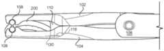
图1A示出本发明具有示例性稳定构件并装载有示例性手术夹的施夹器的第一示例性实施方案的侧视图。1A shows a side view of a first exemplary embodiment of a clip applier of the present invention having an exemplary stabilizing member and loaded with exemplary surgical clips.
图1B示出图1A中第一示例性实施方案的第一透视图。Figure IB shows a first perspective view of the first exemplary embodiment in Figure IA.
图2示出图1A至图1B中第一示例性实施方案的示例性施夹器的第二透视图。FIG. 2 shows a second perspective view of the exemplary clip applier of the first exemplary embodiment of FIGS. 1A-1B .
图3A示出图1A至图2中第一示例性实施方案处于闭合构型的侧视图。3A shows a side view of the first exemplary embodiment of FIGS. 1A-2 in a closed configuration.
图3B示出图1A至图3A中第一示例性实施方案处于闭合构型的透视图。3B shows a perspective view of the first exemplary embodiment of FIGS. 1A-3A in a closed configuration.
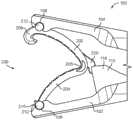
图4示出本发明具有示例性稳定构件的施夹器的第二示例性实施方案的透视图。4 shows a perspective view of a second exemplary embodiment of a clip applier of the present invention having an exemplary stabilizing member.
图5A至图5B示出装载到本发明的示例性施夹器中的示例性手术夹的示例性实施方案的侧视图。5A-5B illustrate side views of an exemplary embodiment of an exemplary surgical clip loaded into an exemplary clip applier of the present invention.
图6示出本发明具有示例性稳定构件的施夹器的第三示例性实施方案的透视图。6 shows a perspective view of a third exemplary embodiment of a clip applier of the present invention having an exemplary stabilizing member.
图7示出图6中第三示例性实施方案的示例性稳定构件的透视图。FIG. 7 shows a perspective view of an exemplary stabilizing member of the third exemplary embodiment in FIG. 6 .
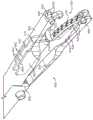
图8示出本发明具有示例性稳定构件并装载有示例性手术夹的施夹器的第四示例性实施方案的透视图。8 shows a perspective view of a fourth exemplary embodiment of a clip applier of the present invention having an exemplary stabilizing member and loaded with exemplary surgical clips.
图9示出本发明具有示例性稳定构件并装载有示例性手术夹的施夹器的第五示例性实施方案的透视图。9 shows a perspective view of a fifth exemplary embodiment of a clip applier of the present invention having an exemplary stabilizing member and loaded with exemplary surgical clips.
图10示出本发明具有示例性稳定构件并装载有示例性手术夹的施夹器的第六示例性实施方案的透视图。10 shows a perspective view of a sixth exemplary embodiment of a clip applier of the present invention having an exemplary stabilizing member and loaded with exemplary surgical clips.
在附图和下文具体实施方式中可使用相同或相似的附图标记指代相同或相似的部分。The same or similar reference numerals may be used in the drawings and the following detailed description to refer to the same or similar parts.
具体实施方式Detailed ways
现将结合附图阐述本发明,其中相同的附图标记通篇可指代相同的元素。根据常规实践,如本文所用,术语“近侧部分”是指装置或其部件中一般更靠近操作或操纵装置按原样使用的医务人员的特定部分,而术语“远侧部分”是指装置或其部件中与近侧部分相反的特定部分,除非本文另作说明。The invention will now be elucidated with reference to the drawings, wherein like reference numerals refer to like elements throughout. In accordance with conventional practice, as used herein, the term "proximal portion" refers to a specific portion of a device or its components that is generally closer to the medical personnel who handles or manipulates the device as it is used, while the term "distal portion" refers to the device or its components. A specific portion of a component as opposed to a proximal portion, unless otherwise specified herein.
本发明总体上涉及施夹器,其配置成在医疗手术过程中提高手术夹的稳定性。施夹器可以包括具有第一钳口构件和第二钳口构件的施夹器,稳定构件部署在其中至少一个钳口构件上。稳定构件和一对钳口构件可以提供至少三个与手术夹的接触点,以减少手术夹在手术过程中相对于施夹器的运动。稳定构件可以包括第一纵壁和第二纵壁,它们在二者之间接纳手术夹的近侧部分并且减少手术夹的横向移动。第一纵壁和第二纵壁的转角可以与近侧部分叠合(例如,在铰接构件处或其近旁)以减少横向移动。然而,当手术夹容纳在钳口构件之间时,稳定构件可以不向近侧邻接近侧部分。换言之,当处于打开构型时,稳定构件可以接合手术夹的近侧部分的上表面、下表面和/或侧表面,但施夹器和稳定构件提供手术夹近侧的空间,以允许手术夹的夹脚构件在闭合期间枢转和/或拉长。在某些实施方案中,稳定构件可以部署在第一钳口构件上并呈闭合构型容纳在第二钳口构件的纵向通道中。因此,第二钳口的纵向通道可以具有较窄的远侧部分和较宽的近侧部分,该近侧部分在闭合构型时容纳稳定构件。这就允许稳定构件的长度足以在施夹器处于打开构型时稳定手术夹,但不会干扰施夹器的闭合。稳定构件可以包括第一纵壁和第二纵壁,它们之间限定纵向空间或空腔。稳定构件可以整合或能移除地固定到第一钳口构件和第二钳口构件中的至少一个钳口构件。在某些应用中,将稳定构件整合到第一钳口构件和第二钳口构件中的至少一个钳口构件特别优选的原因是有助于制造过程。而在某些应用中,可能优选将稳定构件以能移除的方式固定到钳口构件,以例如适应不同尺寸的手术夹,并且稳定构件损坏时能够易于更换。The present invention generally relates to clip appliers configured to increase the stability of surgical clips during medical procedures. The clip applier may include a clip applier having a first jaw member and a second jaw member, the stabilizing member being disposed on at least one of the jaw members. The stabilizing member and the pair of jaw members can provide at least three points of contact with the clip to reduce movement of the clip relative to the clip applier during a procedure. The stabilizing member may include a first longitudinal wall and a second longitudinal wall that receive therebetween the proximal portion of the clip and reduce lateral movement of the clip. The corners of the first and second longitudinal walls may coincide with the proximal portion (eg, at or near the hinge member) to reduce lateral movement. However, the stabilizing member may not proximally adjoin the proximal portion when the clip is received between the jaw members. In other words, when in the open configuration, the stabilizing member may engage the upper, lower, and/or side surfaces of the proximal portion of the clip, but the clip applier and stabilizing member provide space proximal to the clip to allow the clip to The pinch members pivot and/or elongate during closure. In certain embodiments, a stabilizing member can be deployed on the first jaw member and received in the longitudinal channel of the second jaw member in a closed configuration. Accordingly, the longitudinal channel of the second jaw may have a narrower distal portion and a wider proximal portion that accommodates the stabilizing member when in the closed configuration. This allows the stabilizing member to be of sufficient length to stabilize the surgical clip when the clip applier is in the open configuration, but not interfere with closure of the clip applier. The stabilizing member may comprise a first longitudinal wall and a second longitudinal wall defining a longitudinal space or cavity therebetween. The stabilizing member may be integral or removably secured to at least one of the first jaw member and the second jaw member. In some applications, the reason why it is particularly preferred to integrate the stabilizing member into at least one of the first and second jaw members is to facilitate the manufacturing process. In some applications, however, it may be preferable to removably secure the stabilizing member to the jaw member, eg, to accommodate surgical clips of different sizes, and to enable easy replacement of the stabilizing member if damaged.
图1A至图1B示出装载有手术夹200的施夹器100处于打开构型,图2示出不带手术夹200的施夹器100,图3A至图3B示出装载有手术夹200的施夹器100处于闭合构型。如图所示,施夹器100可以具有以能枢转的方式耦接于铰接构件106的第一钳口构件102和第二钳口构件104。第一钳口构件102和第二钳口构件104可以配置成将手术夹200压缩到组织上,以例如结扎血管。1A to 1B show clip applier 100 loaded with
手术夹200可以具有以能枢转的方式连接于铰接构件206的第一夹脚构件202和第二夹脚构件204。第一夹脚构件202可以具有大致凹入的内表面、大致凸出的外表面以及远端上的弯钩构件208。第二夹脚构件204可以具有大致凸起的内表面、大致凹入的外表面以及远端上的尖端构件210。弯钩构件208可以围绕尖端构件210接合和弯转,而第一夹脚构件202和第二夹脚构件204中的一个或两个枢转、伸直和/或拉长。然后,尖端构件210可以容纳在弯钩构件208中,以将手术夹200固定在闭锁构型。第一夹脚构件202和第二夹脚构件204中的每个夹脚构件可以在远侧部分上具有一个或多个凸台构件212。手术夹200的示例性实施方案进一步参阅第4,834,096号美国专利,其公开内容明确整体并入本文。但可设想,施夹器100可以配置成应用任何数目手术夹200的实施方案。
进一步如图所示,第一钳口构件102和第二钳口构件104可以包括远侧部分处的至少一个凹部108和至少一个凹部108近侧的稳定构件110。至少一个凹部108可以横贯延伸穿过第一钳口构件102和第二钳口构件104并配置成以干涉或搭扣配合方式容纳手术夹200的第一夹脚构件202和第二夹脚构件204上的凸台构件212。第一纵向通道120可以延伸穿过第一钳口构件102的内部,将第一钳口构件102分成一对第一延伸部122。第二纵向通道124可以延伸穿过第二钳口构件104的内部,将第二钳口构件104分成一对第二延伸部126。每个延伸部122、126可以具有配置成容纳相对凸台构件212的凹部108,并且第一纵向通道120和第二纵向通道124中的每个纵向通道可以配置成容纳手术夹200的一部分。第二纵向通道124可以包括较宽的近侧部分128(如图1B所示),其配置成在第一钳口构件102和第二钳口构件104处于闭合构型时容纳稳定构件110(如图3A至图3B所示)。As further shown, the
稳定构件110可以配置成通过减小近侧部分的横向移动来对准手术夹200。稳定构件110可以与第一钳口构件102制成一体并朝向第二钳口构件104向内延伸。稳定构件110可以具有第一纵壁和第二纵壁112,其大致平坦的内侧表面和/或外侧表面不妨碍施夹器100和/或手术夹200的闭合。纵壁112可以在其间限定空腔114,并且纵壁112可以在稳定构件110的近侧部分116处结合,以在近端处闭合空腔114。当第一钳口构件102和第二钳口构件104处于打开构型并整个闭合时,通过在手术夹200的近侧部分的近侧提供空间,稳定构件110可以不向近侧邻接手术夹200的近侧部分。随着手术夹200闭合并且弯钩构件208围绕尖端构件210弯转时,近侧空间可以允许弯曲的夹脚构件202、204枢转、伸直和/或拉长。稳定构件110可以具有内部118(例如纵壁112的转角),当第一钳口构件102和第二钳口构件104处于打开构型时,该内部118与手术夹200叠合。因此,在打开构型中,稳定构件110可以将手术夹容纳在空腔114中,并且第一纵壁和第二纵壁112可以与手术夹200的近侧部分叠合。随着第一钳口构件102和第二钳口构件104闭合,稳定构件110可以滑过手术夹200的近侧部分,而当手术夹200容纳在空腔114中时,第二纵向通道124可以容纳稳定构件110。内部118也可以具有大致平坦的内表面,该内表面在闭合构型中邻接第二纵向通道124的大致平坦的内壁130,以提供止动(如图3A所示)。稳定构件110也可以具有从第一钳口构件102大致垂直延伸的远侧表面以及从第一钳口构件102成锐角向远侧延伸的近侧表面。Stabilizing
图4示出处于打开构型的施夹器300。如图所示,施夹器300可以具有以能枢转的方式耦接于铰接构件306的第一钳口构件302和第二钳口构件304。第一钳口构件302和第二钳口构件304可以配置成装载有手术夹200并将手术夹200压缩到组织上,类似于上文所述。FIG. 4 shows
进一步如图所示,第一钳口构件302和第二钳口构件304可以包括远侧部分处的至少一个凹部308和至少一个凹部308近侧的稳定构件310。至少一个凹部308可以横贯延伸穿过第一钳口构件302和第二钳口构件304并配置成以干涉或搭扣方式容纳手术夹200的第一夹脚构件202和第二夹脚构件204上的凸台构件212。第一纵向通道320可以延伸穿过第一钳口构件302的内部,将第一钳口构件302分成一对第一延伸部322。第二纵向通道324可以延伸穿过第二钳口构件304的内部,将第二钳口构件304分成一对第二延伸部326。每个延伸部322、326可以具有配置成容纳相对凸台构件212的凹部308,并且第一纵向通道320和第二纵向通道324中的每个纵向通道可以配置成容纳手术夹200的一部分。第二纵向通道324可以包括较宽的近侧部分328,其配置成在第一钳口构件302和第二钳口构件304处于闭合构型时容纳稳定构件310(类似于图3A至图3B所示)。As further shown, the
稳定构件310可以配置成通过减小近侧部分的横向移动来对准手术夹200。稳定构件310可以与第一钳口构件302制成一体并朝向第二钳口构件304向内延伸。稳定构件310可以具有第一纵壁和第二纵壁312,其大致平坦的内侧表面和/或外侧表面不妨碍施夹器100和/或手术夹200的闭合。纵壁312可以在其间限定空腔314,并且纵壁312可以在近侧部分处间隔开,以提供空腔314的开口近端。当第一钳口构件302和第二钳口构件304处于打开构型并整个闭合时,通过在手术夹200的近侧部分的近侧提供空间,稳定构件310可以不向近侧邻接手术夹200的近侧部分。随着手术夹200闭合并且弯钩构件208围绕尖端构件210弯转时,近侧空间可以允许弯曲的夹脚构件202、204枢转、伸直和/或延长。稳定构件310可以具有内部318(例如纵壁312的转角),当第一钳口构件302和第二钳口构件304处于打开构型时,该内部118与手术夹200叠合。因此,在打开构型中,稳定构件310可以将手术夹容纳在空腔314中,并且第一纵壁和第二纵壁312可以与手术夹200的近侧部分叠合。随着第一钳口构件302和第二钳口构件304闭合,稳定构件310可以滑过手术夹200的近侧部分,而当手术夹200容纳在空腔314中时,第二纵向通道324可以容纳稳定构件310。内部318也可以具有大致平坦的内表面,该内表面在闭合构型中邻接第二纵向通道324的大致平坦的内壁330,以提供止动。稳定构件310也可以具有从第一钳口构件302成锐角向远侧延伸的远侧表面以及从第一钳口构件302成锐角向远侧延伸的近侧表面。Stabilizing
图5A至图5B示出手术夹200装载到施夹器100中的第二实施方案。如图所示,手术夹200可以包括从手术夹200的近侧部分延伸的尾部或延伸构件220,其配置成容纳在稳定构件110中。延伸构件220可以从近侧部分(例如铰接构件部分206)向近侧延伸并具有垂向弯曲的弯钩部分。延伸构件220的宽度可以小于铰接构件部分206和/或夹脚构件202、204的宽度。手术夹200处于如图5A至图5B所示的任一取向时,延伸构件220均可促进将手术夹200装载到第一钳口构件102与第二钳口构件104之间并进入空腔114。图5A至图5B示出手术夹200的第二实施方案被装载到施夹器100中,但手术夹200的第二实施方案可以被装载到任何数目的其他施夹器中,包括本发明的其他实施方案。5A-5B illustrate a second embodiment of
图6示出处于打开构型的施夹器200,其装载有手术夹200。如图所示,施夹器400可以具有以能枢转的方式耦接于铰接构件(未示出)的第一钳口构件402和第二钳口构件404。第一钳口构件402和第二钳口构件404可以配置成压缩手术夹200,类似于上文所述。FIG. 6 shows
进一步如图所示,第一钳口构件402和第二钳口构件404可以包括远侧部分处的至少一个凹部408和至少一个凹部408近侧的稳定构件410。至少一个凹部408可以横贯延伸穿过第一钳口构件402和第二钳口构件404并配置成以干涉或搭扣方式容纳手术夹200的第一夹脚构件202和第二夹脚构件204上的凸台构件212。第一纵向通道420可以延伸穿过第一钳口构件402的内部,将第一钳口构件402分成一对第一延伸部422。第二纵向通道424可以延伸穿过第二钳口构件404的内部,将第二钳口构件404分成一对第二延伸部426。每个延伸部422、426可以具有配置成容纳相对凸台构件212的凹部408,并且第一纵向通道420和第二纵向通道424中的每个纵向通道可以配置成容纳手术夹200的一部分。第一纵向通道420可以配置成容纳稳定构件410的第一端部(如图6所示),第二纵向通道424可以包括较宽的近侧部分(未示出),其配置成在第一钳口构件402和第二钳口构件404处于闭合构型时容纳稳定构件410的第二端部(类似于图3A至图3B所示)。As further shown, the
稳定构件410可以配置成通过减小近侧部分的横向移动来对准手术夹200。稳定构件410可以能移除的方式固定到第一钳口构件402并从第一钳口构件402朝向第二钳口构件404向内延伸。稳定构件410可以具有第一纵壁和第二纵壁412,其大致平坦的内侧表面和/或外侧表面不妨碍施夹器400和/或手术夹200的闭合。纵壁412可以在其间限定空腔414,并且纵壁412可以连接以在近端处闭合空腔514。当第一钳口构件402和第二钳口构件404处于打开构型并整个闭合时,通过在手术夹200的近侧部分的近侧提供空间,稳定构件410可以不向近侧邻接手术夹200的近侧部分。随着手术夹200闭合并且弯钩构件208围绕尖端构件210弯转时,近侧空间可以允许弯曲的夹脚构件202、204枢转、伸直和/或延长。稳定构件410可以具有内部418(例如纵壁412的转角),当第一钳口构件402和第二钳口构件404处于打开构型时,该内部118与手术夹200叠合。因此,在打开构型中,稳定构件410可以将手术夹容纳在空腔414中,并且第一纵壁和第二纵壁412可以与手术夹200的近侧部分叠合。随着第一钳口构件402和第二钳口构件404闭合,稳定构件410可以滑过手术夹200的近侧部分,而当手术夹200容纳在空腔414中时,第二纵向通道424可以容纳稳定构件410。Stabilizing
进一步如图7所示,稳定构件410可以包括挡块,其长度配置成沿着钳口构件402、404的内表面延伸,基本上大于高度和宽度。稳定构件410的内部418可以具有锥形的平坦内表面,该内表面在闭合构型中邻接第二纵向通道424的大致平坦的内壁(未示出),以提供止动。如图6所示,稳定构件410可以固定在第一钳口构件402的纵向通道420中并且进一步包括固定构件(例如凸部)440,其配置成以能释放的方式接合和/或连锁第一钳口构件402中的固定构件(例如狭槽)442。可以在凸部440与狭槽442之间创建干涉和/或搭扣配合,以使稳定构件410以能释放的方式固定到第一钳口构件402。因此,稳定构件410可以是一次性部件,可以例如在外科手术之后将其移除和/或丢弃。就此而言,稳定构件410可以用于施加一个或多个手术夹200以结扎组织,然后可以从施夹器400中移除并丢弃稳定构件410。因此,稳定构件410可以由便宜的塑料构成,若损坏则可易于更换。As further shown in FIG. 7, the stabilizing
图8示出处于打开构型的施夹器500,其装载有手术夹200。如图所示,施夹器500可以具有以能枢转的方式耦接于铰接构件506的第一钳口构件502和第二钳口构件504。第一钳口构件502和第二钳口构件504可以配置成压缩手术夹200,类似于上文所述。FIG. 8 shows
进一步如图所示,第一钳口构件502和第二钳口构件504可以包括远侧部分处的至少一个凹部508和至少一个凹部508近侧的稳定构件510。至少一个凹部508可以横贯延伸穿过第一钳口构件502和第二钳口构件504并配置成以干涉或搭扣方式容纳手术夹200的第一夹脚构件202和第二夹脚构件204上的凸台构件212。第一纵向通道520可以延伸穿过第一钳口构件502的内部,将第一钳口构件502分成一对第一延伸部522。第二纵向通道524可以延伸穿过第二钳口构件504的内部,将第二钳口构件504分成一对第二延伸部526。每个延伸部522、526可以具有配置成容纳相对凸台构件212的凹部508,并且第一纵向通道520和第二纵向通道524中的每个纵向通道可以配置成容纳手术夹200的一部分。第一纵向通道520可以配置成容纳稳定构件510的第一端部(如图8所示),第二纵向通道524可以包括较宽的近侧部分(未示出),其配置成在第一钳口构件502和第二钳口构件504处于闭合构型时容纳稳定构件510的第二端部。(类似于图3A至图3B所示)。As further shown, the
稳定构件510可以配置成通过减小近侧部分的横向移动来对准手术夹200。稳定构件510可以具有整体固定到第一钳口构件502的第一近侧部分552以及可移除地固定到第一部分552的第二远侧部分554。第二部分554可以具有第一纵壁和第二纵壁512,其大致平坦的内侧表面和/或外侧表面不妨碍施夹器500和/或手术夹200的闭合。纵壁512可以在其间限定空腔514,并且纵壁512可以连结以在近端处闭合空腔514。当第一钳口构件502和第二钳口构件504处于打开构型并整个闭合时,通过在手术夹200的近侧部分的近侧提供空间,稳定构件510可以不向近侧邻接手术夹200的近侧部分。随着手术夹200闭合并且弯钩构件208围绕尖端构件210弯转时,近侧空间可以允许弯曲的夹脚构件202、204枢转、伸直和/或拉长。稳定构件510可以具有内部518(例如纵壁412的转角),当第一钳口构件502和第二钳口构件504处于打开构型时,该内部118与手术夹200叠合。因此,在打开构型中,稳定构件510可以将手术夹容纳在空腔514中,并且第一纵壁和第二纵壁512可以与手术夹200的近侧部分叠合。随着第一钳口构件502和第二钳口构件504闭合,稳定构件510可以滑过手术夹200的近侧部分,而当手术夹200容纳在空腔514中时,第二纵向通道524可以容纳稳定构件510。Stabilizing
进一步如图8所示,第二部分554可以是可释放地固定到第一部分552的挡块。第二部分554可以通过若干不同方式可释放地固定到第一部分552。例如,如图8所示,第一部分552可以具有第一凸台构件556和第二凸台构件558,每个凸台构件具有扩大的远端。第一凸台构件556可以垂直延伸穿过第二构件554的垂向狭槽557,并且第二凸台构件558可以横向延伸穿过第二构件554的侧向狭槽559。采用这种方式,凸台构件556、228与狭槽557、559之间的相互作用可以在垂向和横向上将第二部分554固定到第一钳口构件502上。扩大的远端可以允许第二部分554以干涉配合搭扣到第一部分552上,以助于附接和移除。在另一种实施方案中,第一部分552可以具有多个尖头,这些尖头配置成容纳在第二部分554上的孔眼中,以将第二部分554固定到第一钳口构件502。稳定构件510可以是一次性部件,可以例如在外科手术之后将其移除和/或丢弃。就此而言,稳定构件510可以用于施加一个或多个手术夹200以结扎组织,然后可以从施夹器500中移除并丢弃稳定构件510。因此,稳定构件410可以由便宜的塑料构成,若损坏则可易于更换。As further shown in FIG. 8 , the
图9示出处于打开构型的施夹器600,其装载有手术夹200。如图所示,施夹器600可以具有以能枢转的方式耦接于铰接构件606的第一钳口构件602和第二钳口构件604。第一钳口构件602和第二钳口构件604可以配置成压缩手术夹200,类似于上文所述。FIG. 9 shows
进一步如图所示,第一钳口构件602和第二钳口构件604可以包括远侧部分处的至少一个凹部608和至少一个凹部608近侧的稳定构件610。至少一个凹部608可以横贯延伸穿过第一钳口构件602和第二钳口构件604并配置成以干涉或搭扣方式容纳手术夹200的第一夹脚构件202和第二夹脚构件204上的凸台构件212。第一纵向通道620可以延伸穿过第一钳口构件602的内部,将第一钳口构件602分成一对第一延伸部622。第二纵向通道624可以延伸穿过第二钳口构件604的内部,将第二钳口构件604分成一对第二延伸部626。每个延伸部622、626可以具有配置成容纳相对凸台构件212的凹部608,并且第一纵向通道620和第二纵向通道624中的每个纵向通道可以配置成容纳手术夹200的一部分。第一纵向通道620可以配置成在打开构型时容纳稳定构件610的第一端部(如图9所示),第二纵向通道624可以包括较宽的近侧部分628,其配置成在第一钳口构件602和第二钳口构件604处于闭合构型时容纳稳定构件610的第二端部(类似于图3A至图3B所示)。As further shown, the
稳定构件610可以包括侧向分开的第一纵板或纵壁662和第二纵板或纵壁664并且配置成通过减小近侧部分的横向移动来对准手术夹200。纵壁662、664可以从第一钳口构件602向内延伸。纵壁662、664可以可移除地固定到第一钳口构件602并朝向第二钳口构件604向内延伸。纵壁662、664具有大致平坦的内侧表面和/或外侧表面,这些表面不妨碍施夹器600和/或手术夹200的闭合。纵壁662、664可以在其间限定空腔614并可平行延伸,具有间隔开的近端和远端。当第一钳口构件602和第二钳口构件604处于打开构型并整个闭合时,通过在手术夹200的近侧部分的近侧提供空间,稳定构件610可以不向近侧邻接手术夹200的近侧部分。随着手术夹200闭合并且弯钩构件208围绕尖端构件210弯转时,近侧空间可以允许弯曲的夹脚构件202、204枢转、伸直和/或拉长。稳定构件610可以具有内部618(例如纵壁662、664的转角),当第一钳口构件602和第二钳口构件604处于打开构型时,该内部618与手术夹200叠合。因此,在打开构型中,稳定构件610可以将手术夹容纳在空腔614中,并且第一纵壁662和第二纵壁664可以与手术夹200的近侧部分叠合。随着第一钳口构件602和第二钳口构件604闭合,稳定构件610可以滑过手术夹200的近侧部分,而当手术夹200容纳在空腔614中时,第二纵向通道624可以容纳稳定构件610。Stabilizing
进一步如图所示,第一纵板或纵壁662和第二纵板或纵壁664可以是分立部件,其中每个部件可释放地附接到第一钳口构件602。第一纵壁622和第二纵壁664可以固定在第一钳口构件602的纵向通道620中并且均包括固定构件(例如凸部)640,其配置成以能释放的方式接合和/或连锁第一钳口构件602中的固定构件(例如狭槽)642。可以在凸部640与狭槽642之间创建干涉和/或搭扣配合,以使稳定构件610以能释放的方式固定到第一钳口构件602。因此,稳定构件610可以包括一次性部件,可以例如在外科手术之后将其移除和/或丢弃。就此而言,稳定构件610可以用于施加一个或多个手术夹200以结扎组织,然后可以从施夹器600中移除并丢弃稳定构件610。因此,稳定构件410可以由便宜的塑料构成,若损坏则可易于更换。As further shown, the first longitudinal plate or
图10示出处于打开构型的施夹器700,其装载有手术夹200。如图所示,施夹器700可以具有以能枢转的方式耦接于铰接构件706的第一钳口构件702和第二钳口构件704。第一钳口构件702和第二钳口构件704可以配置成压缩手术夹200,类似于上文所述。FIG. 10 shows clip applier 700 loaded with
进一步如图所示,第一钳口构件702和第二钳口构件704可以包括远侧部分处的至少一个凹部708和至少一个凹部708近侧的稳定构件710。至少一个凹部708可以横向延伸穿过第一钳口构件702和第二钳口构件704并配置成以干涉或搭扣方式容纳手术夹200的第一夹脚构件202和第二夹脚构件204上的凸台构件212。第一纵向通道720可以延伸穿过第一钳口构件702的内部,将第一钳口构件702分成一对第一延伸部722。第二纵向通道724可以延伸穿过第二钳口构件704的内部,将第二钳口构件704分成一对第二延伸部726。每个延伸部722、726可以具有配置成容纳相对凸台构件212的凹部708,并且第一纵向通道720和第二纵向通道724中的每个纵向通道可以配置成容纳手术夹200的一部分。在打开构型中,第一纵向通道720和第二纵向通道724中的每个纵向通道可以具有较宽的近侧部分628,其容纳纵壁762、764中的一个纵壁的第一端部,如图10所示。在闭合构型中,相对的第一纵向通道720和第二纵向通道724的较宽近侧部分728可以容纳另一个纵壁762、764的第二端部。因此,其中每个较宽近侧部分728可以配置成在闭合构型中容纳纵壁762、764。As further shown, the
稳定构件710可以配置成通过减小近侧部分的横向移动来对准手术夹200。稳定构件710可以包括从第一钳口构件702向内延伸的第一纵板或纵壁762以及从第一钳口构件704向内延伸的第二纵板或纵壁764。纵壁762、764可以能移除地固定到相应的钳口构件702、704并且它们大致平坦的内侧表面和/或外侧表面不妨碍施夹器700和/或手术夹200的闭合。纵壁712可以在其间限定空间并且可以具有间隔开的近端和远端。当第一钳口构件702和第二钳口构件704处于打开构型并整个闭合时,通过在手术夹200的近侧部分的近侧提供空间,稳定构件710可以不向近侧邻接手术夹200的近侧部分。随着手术夹200闭合并且弯钩构件208围绕尖端构件210弯转时,近侧空间可以允许弯曲的夹脚构件202、204枢转、伸直和/或拉长。稳定构件710可以具有内部718(例如纵壁762、764的转角),当第一钳口构件702和第二钳口构件704处于打开构型时,该内部618与手术夹200叠合。因此,在打开构型中,稳定构件710可以将手术夹容纳在空间中,并且第一纵壁762和第二纵壁764可以与手术夹200的近侧部分叠合。随着第一钳口构件702和第二钳口构件704闭合,稳定构件610可以滑过手术夹200的近侧部分,并且当手术夹200容纳在这个空间中时,第二纵向通道724可以容纳稳定构件710。Stabilizing
进一步如图所示,第一纵板或纵壁762和第二纵板或纵壁764可以是分立部件,其中每个部件可释放地附接到相应的钳口构件702、704。第一纵壁622和第二纵壁764可以固定在相应钳口构件702、704的纵向通道720、724中并且均包括固定构件(例如凸部)740,其配置成以能释放的方式接合和/或连锁钳口构件702、704中的固定构件(例如狭槽)742。可以在凸部740与狭槽742之间创建干涉和/或搭扣配合,以使纵壁762、764以能释放的方式固定到钳口构件702、704。因此,稳定构件710可以包括一次性部件,可以例如在外科手术之后将其移除和/或丢弃。就此而言,稳定构件710可以用于施加一个或多个手术夹200以结扎组织,然后可以从施夹器700中移除并丢弃稳定构件710。因此,稳定构件410可以由便宜的塑料构成,若损坏则可易于更换。As further shown, the first longitudinal plate or
因此,施夹器的各种实施方案可以提供至少三个与手术夹的接触点。施夹器可以接合手术夹的远侧部分,使凹部接合到凸台构件,并且施夹器可以通过将手术夹的近侧部分容纳在稳定构件的空腔中而横向对齐手术夹。纵壁可以减少近侧部分的横向移动并防止手术夹拖尾。Accordingly, various embodiments of the clip applier can provide at least three points of contact with the surgical clips. The clip applier can engage the distal portion of the surgical clip with the recess engaging the boss member, and the clip applier can laterally align the surgical clip by receiving the proximal portion of the surgical clip within the cavity of the stabilizing member. The longitudinal wall reduces lateral movement of the proximal portion and prevents clip tailing.
本发明的手术夹的各种实施方案可以制成任何合适的尺寸并且可以应用于任意多个组织,例如血管、淋巴结、神经、输卵管或心脏组织。手术夹可以由任何合适的生物相容材料构成,例如某些金属和聚合物。但实践中,本发明特别适用于聚合物夹。因此,手术夹优选具有由适合的强生物相容性工程塑料形成的单件式整体聚合体,如通常用于外科植入物的类型。示例性材料包括均聚物或共聚物聚缩醛、聚对苯二甲酸乙二醇酯(PET)、聚对苯二甲酸丁二醇酯(PBT)、聚甲醛或具有类似性质的其他热塑性材料,这些材料可以注塑、挤出或以其他方式加工成类似制品。Various embodiments of surgical clips of the present invention can be made in any suitable size and can be applied to any number of tissues, such as blood vessels, lymph nodes, nerves, fallopian tubes, or cardiac tissue. Surgical clips may be constructed of any suitable biocompatible material, such as certain metals and polymers. In practice, however, the invention is particularly applicable to polymer clips. Accordingly, the surgical clip preferably has a one-piece monolithic polymer formed from a suitable strong biocompatible engineering plastic, such as the type commonly used for surgical implants. Exemplary materials include homopolymer or copolymer polyacetal, polyethylene terephthalate (PET), polybutylene terephthalate (PBT), polyoxymethylene, or other thermoplastic materials with similar properties , these materials can be injection molded, extruded, or otherwise processed into similar products.
本发明的许多特征和优点参阅本说明书将显而易见,因此所附权利要求旨在涵盖本发明落入本发明真实精神与范围内的全部特征和优点。此外,本领域技术人员容易设想许多修改和变型,因此本发明不局限于图示和描述的确切构造和操作,可以采用本发明范围内的全部适当修改和等效方案。The many features and advantages of the invention will be apparent from this specification, and thus, the appended claims are intended to cover all such features and advantages of the invention as fall within the true spirit and scope of the invention. Furthermore, many modifications and variations will readily occur to those skilled in the art, and thus the invention is not limited to the exact construction and operation shown and described, and all suitable modifications and equivalents within the scope of the invention may be employed.
Claims (28)
Priority Applications (1)
| Application Number | Priority Date | Filing Date | Title |
|---|---|---|---|
| CN202310541341.9ACN116784923A (en) | 2017-03-21 | 2018-03-21 | Clip applier with stabilizing member |
Applications Claiming Priority (3)
| Application Number | Priority Date | Filing Date | Title |
|---|---|---|---|
| US201762474544P | 2017-03-21 | 2017-03-21 | |
| US62/474,544 | 2017-03-21 | ||
| PCT/US2018/023649WO2018175651A1 (en) | 2017-03-21 | 2018-03-21 | Clip applier having stabilizing member |
Related Child Applications (1)
| Application Number | Title | Priority Date | Filing Date |
|---|---|---|---|
| CN202310541341.9ADivisionCN116784923A (en) | 2017-03-21 | 2018-03-21 | Clip applier with stabilizing member |
Publications (2)
| Publication Number | Publication Date |
|---|---|
| CN110753519A CN110753519A (en) | 2020-02-04 |
| CN110753519Btrue CN110753519B (en) | 2023-06-02 |
Family
ID=63581689
Family Applications (2)
| Application Number | Title | Priority Date | Filing Date |
|---|---|---|---|
| CN202310541341.9APendingCN116784923A (en) | 2017-03-21 | 2018-03-21 | Clip applier with stabilizing member |
| CN201880020531.3AActiveCN110753519B (en) | 2017-03-21 | 2018-03-21 | Clip appliers with stabilizing members |
Family Applications Before (1)
| Application Number | Title | Priority Date | Filing Date |
|---|---|---|---|
| CN202310541341.9APendingCN116784923A (en) | 2017-03-21 | 2018-03-21 | Clip applier with stabilizing member |
Country Status (5)
| Country | Link |
|---|---|
| US (3) | US11266408B2 (en) |
| EP (2) | EP4470482A3 (en) |
| JP (3) | JP7026127B2 (en) |
| CN (2) | CN116784923A (en) |
| WO (1) | WO2018175651A1 (en) |
Families Citing this family (32)
| Publication number | Priority date | Publication date | Assignee | Title |
|---|---|---|---|---|
| JP6873267B2 (en) | 2017-03-21 | 2021-05-19 | テレフレックス メディカル インコーポレイテッド | Clip applier with stabilizer |
| WO2018175610A1 (en) | 2017-03-21 | 2018-09-27 | Teleflex Medical Incorporated | Surgical clip and clip applier |
| CN116784923A (en) | 2017-03-21 | 2023-09-22 | 泰利福医疗公司 | Clip applier with stabilizing member |
| US12023041B2 (en) | 2017-03-21 | 2024-07-02 | Teleflex Medical Incorporated | Clip applier |
| JP7159189B2 (en) | 2017-03-21 | 2022-10-24 | テレフレックス メディカル インコーポレイテッド | Flexible stabilizing member for clip applier |
| CA3068282C (en) | 2017-06-22 | 2022-06-28 | Teleflex Medical Incorporated | Surgical clip |
| US20190133590A1 (en) | 2017-11-03 | 2019-05-09 | Covidien Lp | Ligation clip with controlled tissue compression |
| ES2981210T3 (en) | 2017-11-14 | 2024-10-07 | Teleflex Medical Inc | Surgical clip |
| US10932789B2 (en) | 2018-04-11 | 2021-03-02 | Covidien Lp | Ligation clip with latching and retention features |
| US10932788B2 (en) | 2018-04-11 | 2021-03-02 | Covidien Lp | Ligation clip with latching and retention features |
| US11033279B2 (en) | 2018-04-24 | 2021-06-15 | Covidien Lp | Ligation clip with retention features |
| US11304703B2 (en) | 2018-05-25 | 2022-04-19 | Covidien Lp | Ligation clip removal device |
| KR102647625B1 (en)* | 2018-07-18 | 2024-03-14 | 텔리플렉스 메디컬 인코포레이티드 | Clip Appliers and Cartridges |
| US11317923B2 (en) | 2018-08-13 | 2022-05-03 | Covidien Lp | Ligation clip with improved hinge |
| US11304704B2 (en) | 2018-08-22 | 2022-04-19 | Covidien Lp | Surgical clip applier and ligation clips |
| JP7247330B2 (en) | 2018-09-26 | 2023-03-28 | テレフレックス メディカル インコーポレイテッド | Clip applier with stabilizing member |
| US11471165B2 (en) | 2019-05-08 | 2022-10-18 | Covidien Lp | Ligation clip cartridge |
| US11707282B2 (en) | 2019-07-02 | 2023-07-25 | Covidien Lp | Multi-piece ligation clip |
| USD907203S1 (en) | 2019-08-02 | 2021-01-05 | Covidien Lp | Ligation clip |
| USD907204S1 (en) | 2019-08-02 | 2021-01-05 | Covidien Lp | Ligation clip |
| US11395660B2 (en) | 2019-08-05 | 2022-07-26 | Covidien Lp | Stackable ligation clip |
| USD907200S1 (en) | 2019-08-05 | 2021-01-05 | Covidien Lp | Ligation clip |
| US20210068840A1 (en)* | 2019-09-06 | 2021-03-11 | Covidien Lp | Energizable surgical clip applier |
| WO2021062170A1 (en) | 2019-09-26 | 2021-04-01 | Teleflex Medical Incorporated | Clip applier |
| EP4076216A1 (en) | 2019-12-19 | 2022-10-26 | Teleflex Medical Incorporated | Surgical clip |
| US11696764B2 (en) | 2020-01-31 | 2023-07-11 | Covidien Lp | Ligation clip with controlled tissue compression |
| US12114866B2 (en) | 2020-03-26 | 2024-10-15 | Covidien Lp | Interoperative clip loading device |
| DE102020126581A1 (en)* | 2020-10-09 | 2022-04-14 | Aesculap Ag | Application system for medical clips |
| CN113842186B (en)* | 2021-09-10 | 2025-01-21 | 大瓷生物医疗科技(江苏)有限公司 | Sealer structure and split pre-installed sealing clamp structure |
| CA3234122A1 (en)* | 2021-10-14 | 2023-04-20 | Jessica BOYERS | Asymmetric clip applier and cartridge |
| CN116115289A (en)* | 2021-11-12 | 2023-05-16 | 江苏风和医疗器材股份有限公司 | Clip applier |
| EP4386788A1 (en)* | 2022-12-14 | 2024-06-19 | Hitachi Energy Ltd | Power transformer for on-load tap changer application |
Citations (4)
| Publication number | Priority date | Publication date | Assignee | Title |
|---|---|---|---|---|
| EP0469524A1 (en)* | 1990-07-30 | 1992-02-05 | JOHNSON & JOHNSON PROFESSIONAL, INC. | Surgical clip and surgical clip applier with reciprocating sleeve and dual rachet mechanism |
| CA2071372A1 (en)* | 1991-06-18 | 1992-12-19 | Chao C. Chen | Endoscopic suture clip |
| CN101703412A (en)* | 2005-04-14 | 2010-05-12 | 伊西康内外科公司 | Overloading mechanism for medical instrument |
| CN101961260A (en)* | 2010-05-19 | 2011-02-02 | 上海菲捷实业有限公司 | In vivo steering reverse clip applier |
Family Cites Families (294)
| Publication number | Priority date | Publication date | Assignee | Title |
|---|---|---|---|---|
| US929868A (en) | 1908-09-17 | 1909-08-03 | Carl L Mueller | Detachable-jaw tool. |
| US1482290A (en) | 1921-02-02 | 1924-01-29 | Elzi Peter Frank | Bending tool |
| US1728322A (en) | 1928-02-22 | 1929-09-17 | Badrian Max | Device for elastically clamping off the male urethra |
| US2384697A (en) | 1944-10-18 | 1945-09-11 | Riccardi Peter | Umbilical clip |
| US2635238A (en) | 1949-07-11 | 1953-04-21 | Garland Mather | Apparatus for clamping umbilical cords and the like |
| US2626608A (en) | 1949-12-08 | 1953-01-27 | Garland Mather | Clamp for umbilical cords and the like |
| US2598901A (en) | 1950-03-10 | 1952-06-03 | Garland Mather | Clamp for constricting flexible tubular elements and the like |
| US2594102A (en) | 1950-05-03 | 1952-04-22 | Vollmer Leonhard | Automatic inserter for suturing clips |
| US2744251A (en) | 1953-06-04 | 1956-05-08 | Vollmer Leonhard | Automatic inserter for suturing clips |
| US2881762A (en) | 1955-02-09 | 1959-04-14 | Robert J Lowrie | Surgical staple and stapler |
| US2890519A (en) | 1955-08-01 | 1959-06-16 | Storz Instr Co | Surgical spring clip forceps |
| US2813269A (en) | 1956-01-25 | 1957-11-19 | Jacobs John Bay | Implement for applying an umbilical cord seal and identifying newly born babies |
| US2814222A (en) | 1956-07-16 | 1957-11-26 | Emmitt G Sanders | Ferrule crimping pliers with replaceable jaws |
| US3032039A (en) | 1959-05-26 | 1962-05-01 | Jack O Beaty | Arterial and veinous clamp and clamp applicator |
| US3150379A (en)* | 1962-03-01 | 1964-09-29 | Ernest C Wood | Single clip disposable applicator |
| US3172133A (en) | 1962-05-14 | 1965-03-09 | Olympio C Rizzo | Long nose pliers with cutting attachment |
| US3463156A (en) | 1965-05-27 | 1969-08-26 | Edward B Mcdermott | Hemostatic clip and applicator |
| US3446212A (en) | 1965-07-19 | 1969-05-27 | New Research & Dev Lab Inc | Hemostatic clip and applicator therefor |
| US3503398A (en) | 1965-09-10 | 1970-03-31 | American Hospital Supply Corp | Atraumatic clamp for vascular surgery |
| US3503396A (en) | 1967-09-21 | 1970-03-31 | American Hospital Supply Corp | Atraumatic surgical clamp |
| US3503397A (en) | 1967-09-21 | 1970-03-31 | American Hospital Supply Corp | Atraumatic surgical clamp |
| US3766925A (en) | 1971-05-25 | 1973-10-23 | Eljay Hospital Prod Corp | Surgical clamp with cam-action lever |
| US3827438A (en) | 1972-07-10 | 1974-08-06 | G Kees | Aneurysm clip |
| US3867944A (en) | 1972-10-27 | 1975-02-25 | Wood Ernest C | Hemostatic clip and applicator therefor |
| US3954108A (en) | 1972-11-03 | 1976-05-04 | Davis Hugh J | Occlusion clip and instrument for applying same |
| US3874042A (en) | 1973-01-22 | 1975-04-01 | Biospectrum Inc | Clamp for thin walled tubing |
| US3825012A (en) | 1973-04-13 | 1974-07-23 | H Nicoll | Reusable umbilical cord clamp for veterinary use |
| DE2730691C2 (en) | 1976-07-16 | 1982-12-16 | Maruho Co. Ltd., Osaka | Surgical clip, connecting element for several surgical clips and forceps for opening and closing the same |
| US4120302A (en) | 1976-10-08 | 1978-10-17 | American Hospital Supply Corporation | Disposable pads for surgical instruments |
| CA1082552A (en) | 1977-08-05 | 1980-07-29 | Charles H. Klieman | Hemostatic clip applicator |
| US4316468A (en) | 1977-08-05 | 1982-02-23 | Charles H. Klieman | Surgical stapler |
| US4337774A (en) | 1978-06-14 | 1982-07-06 | Metatech Corporation | Micro surgical clip |
| US4428374A (en)* | 1978-12-20 | 1984-01-31 | Auburn Robert M | Umbilical cord clamping assembly |
| US4390019A (en) | 1979-02-28 | 1983-06-28 | Leveen Harry H | Blood vessel clamp |
| US4418694A (en) | 1979-06-18 | 1983-12-06 | Ethicon, Inc. | Non-metallic, bio-compatible hemostatic clips |
| US4527562A (en) | 1979-06-18 | 1985-07-09 | Ethicon, Inc. | Non-metallic, bio-compatible hemostatic clips |
| CA1157335A (en) | 1979-06-18 | 1983-11-22 | Namassivaya Doddi | Plastic ligating clips |
| MX151148A (en) | 1980-02-25 | 1984-10-04 | Johnson & Johnson | IMPROVEMENTS IN HEMOSTATIC FORCEPS |
| US4638804A (en) | 1980-02-25 | 1987-01-27 | Ethicon, Inc. | Double-latched non-metallic, bio-compatible hemostatic clip |
| US4345600A (en) | 1980-08-04 | 1982-08-24 | Senco Products, Inc. | Purse-stringer |
| US4414721A (en) | 1980-11-07 | 1983-11-15 | Hufnagel Charles A | Occlusive clip and applicator for constricting flexible tubular members |
| US4346869A (en) | 1981-03-12 | 1982-08-31 | Macneill Robert L | Tube clamp |
| US4394864A (en) | 1981-04-15 | 1983-07-26 | Jeffrey Sandhaus | Apparatus and method for effecting occlusion of the vas deferens |
| US4550729A (en) | 1981-08-27 | 1985-11-05 | Ethicon, Inc. | Non-metallic, bio-compatible hemostatic clips with interlocking latch means |
| US4570633A (en) | 1981-09-28 | 1986-02-18 | Ethicon, Inc. | Surgical clip applier instrument adapter jaws |
| US4487204A (en) | 1981-10-14 | 1984-12-11 | Nomel | Device for applying haemostatic clips |
| US4471780A (en) | 1982-02-05 | 1984-09-18 | Ethicon, Inc. | Multiple ligating clip applier instrument |
| US4476865A (en) | 1982-02-12 | 1984-10-16 | Ethicon, Inc. | Non-metallic, bio-compatible hemostatic clips |
| US4450840A (en) | 1982-02-26 | 1984-05-29 | Ethicon, Inc. | Ligating clip with flanged base having a recessed engaging face |
| US4487205A (en) | 1982-04-26 | 1984-12-11 | Ethicon, Inc. | Non-metallic, bio-compatible hemostatic clips |
| US4458682A (en) | 1982-08-02 | 1984-07-10 | Ethicon, Inc. | Non-metallic, bio-compatible hemostatic clips (ring lock clips) |
| US4671281A (en) | 1982-09-13 | 1987-06-09 | Ethicon, Inc. | Non-metallic, bio-compatible hemostatic clips (one piece wedge clip) |
| US4492232A (en) | 1982-09-30 | 1985-01-08 | United States Surgical Corporation | Surgical clip applying apparatus having fixed jaws |
| US4519392A (en) | 1982-10-12 | 1985-05-28 | Lingua Robert W | Hemostasing muscle clips for needleless surgery |
| US4534351A (en)* | 1982-10-20 | 1985-08-13 | Senmed, Inc. | Ligator |
| US4444187A (en) | 1982-12-09 | 1984-04-24 | Metatech Corporation | Miniature surgical clip for clamping small blood vessels in brain surgery and the like |
| US4579118A (en) | 1983-06-01 | 1986-04-01 | Ethicon, Inc. | Hemostatic clip with penetration means |
| US4919152A (en) | 1987-03-02 | 1990-04-24 | Ralph Ger | Method of closing the opening of a hernial sac |
| US5127915A (en) | 1984-10-29 | 1992-07-07 | Mattson Philip D | Surgical instrument for severing and clamping an umbilical cord |
| US4589626A (en) | 1985-03-13 | 1986-05-20 | Bioresearch Inc. | Hose clamp |
| US4588160A (en) | 1985-03-27 | 1986-05-13 | Sherwood Medical Company | Tube clamping device |
| US4616651A (en) | 1985-04-15 | 1986-10-14 | Ethicon, Inc. | Surgical clip applier instrument adapter jaws |
| JPH0657218B2 (en) | 1985-05-10 | 1994-08-03 | エチコン・インコ−ポレ−テツド | Ligation clip and clip application device |
| US5047038A (en) | 1985-07-01 | 1991-09-10 | Edward Weck Incorporated | Automatic hemostatic clip applier |
| US4712549A (en) | 1985-07-01 | 1987-12-15 | Edward Weck & Co. | Automatic hemostatic clip applier |
| US4807622A (en) | 1985-09-20 | 1989-02-28 | Kato Hatsujo Kaisha, Ltd. | Tube cutting and separating implement for conduit of blood or the like |
| US4924864A (en) | 1985-11-15 | 1990-05-15 | Danzig Fred G | Apparatus and article for ligating blood vessels, nerves and other anatomical structures |
| US4686983A (en) | 1986-04-08 | 1987-08-18 | Gerald Leisman | Apparatus and method for ligating a body vessel |
| US4716886A (en) | 1986-05-01 | 1988-01-05 | Norman Schulman | Umbilical cord clamp and cutters |
| US4726372A (en) | 1986-09-19 | 1988-02-23 | Metatech Corporation | Hemostatic clip |
| DE3704760C1 (en) | 1987-02-16 | 1988-03-03 | Aesculap Werke Ag | Application device for C-shaped scalp clips |
| US4834090A (en) | 1987-03-02 | 1989-05-30 | Moore J Paul | Suture boot |
| US4822348A (en) | 1987-05-13 | 1989-04-18 | Donn Casey | Surgical clips |
| US4834096A (en) | 1987-10-26 | 1989-05-30 | Edward Weck Incorporated | Plastic ligating clips |
| GB2212201B (en) | 1987-11-10 | 1992-06-03 | Donn Casey | Surgical clip |
| US4870965A (en) | 1988-03-04 | 1989-10-03 | Jahanger Mohammed S | Umbilical cord cutting and clamping device |
| US5053045A (en) | 1988-09-16 | 1991-10-01 | Schmidt Ferenc J | Surgical clip |
| US4942886A (en) | 1989-02-22 | 1990-07-24 | Timmons John W | External incontinency device |
| US5062846A (en) | 1989-03-28 | 1991-11-05 | Edward Weck Incorporated | Penetrating plastic ligating clip |
| US4976722A (en) | 1989-05-22 | 1990-12-11 | Ethicon, Inc. | Surgical hemostatic clips |
| US4938764A (en) | 1989-06-02 | 1990-07-03 | John Glaberson | Tick remover |
| US4938765A (en) | 1989-06-22 | 1990-07-03 | Life Centers, Inc. | Surgical silicon loops |
| US5104395A (en) | 1989-07-03 | 1992-04-14 | Edward Weck Incorporated | Automatic hemostatic clip applicator |
| US4950275A (en) | 1989-07-19 | 1990-08-21 | Cyanamid Italia S.P.A. | Bowel-anastomosis-ring holder pincers |
| US4972949A (en) | 1989-09-26 | 1990-11-27 | Horizon Surgical, Inc. | Hemostatic clip holder for small clips |
| US4936447A (en) | 1989-09-26 | 1990-06-26 | Horizon Surgical Inc. | Hemostatic clip holder |
| US5100416A (en) | 1989-10-17 | 1992-03-31 | Edward Weck Incorporated | Ligating clip applying instrument |
| US5009657A (en) | 1989-12-14 | 1991-04-23 | Mohammed S. Jahanger | Umbilical cord cutting and clamping device |
| US4961499A (en) | 1990-01-04 | 1990-10-09 | Pilling Co. | Hemostatic clip cartridge |
| NZ233737A (en) | 1990-05-18 | 1992-12-23 | Allflex New Zealand | Applicator for one-piece ear tag formed into an annulus |
| US5078731A (en) | 1990-06-05 | 1992-01-07 | Hayhurst John O | Suture clip |
| US5026382A (en) | 1990-08-27 | 1991-06-25 | Horizon Surgical, Inc. | Hemostatic clip |
| FR2666952A1 (en) | 1990-09-18 | 1992-03-20 | Sgs Thomson Microelectronics | SECAM DECODER. |
| US5201416A (en) | 1990-10-22 | 1993-04-13 | Edward Weck Incorporated | Hemostatic clip cartridge |
| US5046611A (en) | 1990-10-22 | 1991-09-10 | Edward Weck Incorporated | Hemostatic clip cartridge |
| US5366458A (en) | 1990-12-13 | 1994-11-22 | United States Surgical Corporation | Latchless surgical clip |
| US5171252A (en) | 1991-02-05 | 1992-12-15 | Friedland Thomas W | Surgical fastening clip formed of a shape memory alloy, a method of making such a clip and a method of using such a clip |
| US5112343A (en) | 1991-04-05 | 1992-05-12 | Edward Weck Incorporated | Endoscopic clip appliers |
| US5160339A (en) | 1991-06-18 | 1992-11-03 | Ethicon, Inc. | Endoscopic suture clip |
| US5163945A (en) | 1991-10-18 | 1992-11-17 | Ethicon, Inc. | Surgical clip applier |
| US5259405A (en) | 1992-01-29 | 1993-11-09 | Hua Chou Kuo | Structure of a barette |
| US5171251A (en) | 1992-03-02 | 1992-12-15 | Ethicon, Inc. | Surgical clip having hole therein and method of anchoring suture |
| US5246450A (en) | 1992-03-10 | 1993-09-21 | Edward Weck Incorporated | High capacity medical clip feeding and dispensing mechanism |
| US5279416A (en) | 1992-06-05 | 1994-01-18 | Edward Weck Incorporated | Ligating device cartridge with separable retainer |
| DK0717962T3 (en) | 1992-06-30 | 1999-10-25 | Sherwood Serv Ag | Modular tie-down clamp applicator |
| US5234449A (en) | 1992-07-16 | 1993-08-10 | Ethicon, Inc. | Suture clip with reduced hinge mass |
| CA2107635C (en) | 1992-10-09 | 1999-08-17 | David T. Green | Surgical clip applier |
| US5330442A (en) | 1992-10-09 | 1994-07-19 | United States Surgical Corporation | Suture retaining clip |
| US5464416A (en) | 1992-11-10 | 1995-11-07 | Ethicon, Inc. | Ligating clip |
| US5330487A (en) | 1992-12-17 | 1994-07-19 | Tfi Acquistion Corp. | Drive mechanism for surgical instruments |
| US5569274A (en) | 1993-02-22 | 1996-10-29 | Heartport, Inc. | Endoscopic vascular clamping system and method |
| CA2120828C (en) | 1993-04-16 | 1999-11-02 | Paul J. Phillips | Surgical hemostatic clip |
| US5431668A (en) | 1993-04-29 | 1995-07-11 | Ethicon, Inc. | Ligating clip applier |
| US5549621A (en) | 1993-05-14 | 1996-08-27 | Byron C. Sutherland | Apparatus and method for performing vertical banded gastroplasty |
| US5405344A (en) | 1993-09-30 | 1995-04-11 | Ethicon, Inc. | Articulable socket joint assembly for an endoscopic instrument for surgical fastner track therefor |
| DK110193A (en) | 1993-09-30 | 1995-03-31 | Per Baunsgaard | Terminal device |
| US5607436A (en) | 1993-10-08 | 1997-03-04 | United States Surgical Corporation | Apparatus for applying surgical clips |
| US5462555A (en) | 1993-12-30 | 1995-10-31 | United States Surgical Corporation | Umbilical cord clip and applicator |
| GB9400739D0 (en) | 1994-01-15 | 1994-03-16 | Femcare Ltd | Medical clip |
| US5501693A (en) | 1994-07-06 | 1996-03-26 | United States Surgical Corporation | Surgical hemostatic clip |
| US5626585A (en) | 1994-09-16 | 1997-05-06 | United States Surgical Corporation | Ligating clip advance |
| US5487746A (en) | 1994-11-23 | 1996-01-30 | Yu; George W. | Surgical clip having a longitudinal opening through which clamped tissue protrudes |
| US5695505A (en) | 1995-03-09 | 1997-12-09 | Yoon; Inbae | Multifunctional spring clips and cartridges and applicators therefor |
| US5667516A (en) | 1995-05-01 | 1997-09-16 | Allen; Sean A. | Mechanism for cutting an umbilical cord |
| US5575796A (en) | 1995-05-17 | 1996-11-19 | Utah Medical Products, Inc. | Umbilical cord cutter and sampler |
| US5908430A (en) | 1995-06-07 | 1999-06-01 | Appleby; Timothy | Easy loading hemostatic clip and cartridge |
| US5713912A (en) | 1995-08-30 | 1998-02-03 | Stress Management, Inc. | Ligating clip having ramp-shaped vessel clamping members and tool for applying same |
| US5700270A (en) | 1995-10-20 | 1997-12-23 | United States Surgical Corporation | Surgical clip applier |
| US5810853A (en) | 1996-01-16 | 1998-09-22 | Yoon; Inbae | Knotting element for use in suturing anatomical tissue and methods therefor |
| US6015417A (en) | 1996-01-25 | 2000-01-18 | Reynolds, Jr.; Walker | Surgical fastener |
| US5846255A (en) | 1996-01-31 | 1998-12-08 | Casey Medical Products Limited | Surgical clip |
| DE19603889C2 (en) | 1996-02-03 | 1999-05-06 | Aesculap Ag & Co Kg | Surgical application device |
| US5797922A (en) | 1996-02-06 | 1998-08-25 | Balagan Medical Inc. | Umbilical cord clamping device |
| WO1997038634A1 (en) | 1996-04-18 | 1997-10-23 | Applied Medical Resources Corporation | Malleable clip applier and method |
| US5925052A (en) | 1996-06-26 | 1999-07-20 | Simmons; Paul L. | Umbilical surgical scissors |
| FR2751863B1 (en) | 1996-08-01 | 1999-01-22 | Vitalitec International | HEMOSTATIC CLIPS SUPPORT |
| US5722982A (en) | 1996-09-26 | 1998-03-03 | University Technology Corporation | Strabismus surgery apparatus and method |
| US5713911A (en) | 1996-10-03 | 1998-02-03 | United States Surgical Corporation | Surgical clip |
| US5833696A (en) | 1996-10-03 | 1998-11-10 | United States Surgical Corporation | Apparatus for applying surgical clips |
| US5954731A (en) | 1997-07-29 | 1999-09-21 | Yoon; Inbae | Surgical instrument with multiple rotatably mounted spreadable end effectors |
| US5972003A (en) | 1997-10-01 | 1999-10-26 | Sherwood Services Ag | Single-free ligation clip module |
| US5921991A (en) | 1997-10-23 | 1999-07-13 | Biomax Technologies Inc. | Multi-colored umbilical cord clamp |
| US6050996A (en) | 1997-11-12 | 2000-04-18 | Sherwood Services Ag | Bipolar electrosurgical instrument with replaceable electrodes |
| DE19752331C1 (en) | 1997-11-26 | 1999-09-30 | Aesculap Ag & Co Kg | Magazine for a surgical clip applier |
| US6273887B1 (en) | 1998-01-23 | 2001-08-14 | Olympus Optical Co., Ltd. | High-frequency treatment tool |
| US6010516A (en) | 1998-03-20 | 2000-01-04 | Hulka; Jaroslav F. | Bipolar coaptation clamps |
| US6131576A (en) | 1998-03-23 | 2000-10-17 | Davis; Paul K. | Male incontinence clamp, kit and method of use |
| US5997548A (en) | 1998-07-22 | 1999-12-07 | Jahanger; Mohammed S. | Umbilical cord cutting and clamping device |
| US6099539A (en) | 1998-07-27 | 2000-08-08 | Thomas J. Fogarty | Surgical clamp pad with interdigitating teeth |
| US6277117B1 (en) | 1998-10-23 | 2001-08-21 | Sherwood Services Ag | Open vessel sealing forceps with disposable electrodes |
| US6013088A (en) | 1998-11-17 | 2000-01-11 | Karavidas; Theocharis | Surgical clamp with removable tips |
| DE19858581C2 (en) | 1998-12-18 | 2001-03-08 | Aesculap Ag & Co Kg | Vascular clip |
| US6210419B1 (en) | 1998-12-18 | 2001-04-03 | Aesculap Ag & Co. Kg | Surgical clip |
| US6217590B1 (en) | 1999-01-22 | 2001-04-17 | Scion International, Inc. | Surgical instrument for applying multiple staples and cutting blood vessels and organic structures and method therefor |
| US6387112B1 (en) | 1999-06-18 | 2002-05-14 | Novare Surgical Systems, Inc. | Surgical clamp having replaceable pad |
| US6228104B1 (en) | 1999-06-18 | 2001-05-08 | Novare Surgical Systems, Inc. | Surgical clamp having replaceable pad |
| US6273902B1 (en) | 1999-06-18 | 2001-08-14 | Novare Surgical Systems, Inc. | Surgical clamp having replaceable pad |
| DE19934634C1 (en) | 1999-07-23 | 2000-12-21 | Aesculap Ag & Co Kg | Surgical clip application instrument has clips in clip magazine fed forwards via reciprocating displacement plate acted on by displacement device at point at least halfway along its length |
| GB2353710A (en) | 1999-08-06 | 2001-03-07 | Henleys Medical Supplies Ltd | Umbilical cord clamp |
| IL132913A (en) | 1999-11-14 | 2004-09-27 | Porat Michael | Device and method for clamping and cutting a flexible deformable tube |
| GB9927040D0 (en) | 1999-11-17 | 2000-01-12 | Femcare Ltd | Medical clips |
| US6695854B1 (en) | 1999-11-29 | 2004-02-24 | General Surgical Innovations, Inc. | Blood vessel clip and applicator |
| US7963964B2 (en) | 2000-02-10 | 2011-06-21 | Santilli Albert N | Surgical clamp assembly with electrodes |
| US6419682B1 (en) | 2000-03-24 | 2002-07-16 | Timothy Appleby | Hemostatic clip cartridge |
| US6391035B1 (en) | 2000-03-24 | 2002-05-21 | Timothy Appleby | Hemostatic clip removal instrument |
| US6926712B2 (en) | 2000-03-24 | 2005-08-09 | Boston Scientific Scimed, Inc. | Clamp having at least one malleable clamp member and surgical method employing the same |
| US6349727B1 (en) | 2000-05-25 | 2002-02-26 | Pos-T-Vac, Inc. | Penile clamp for inhibiting incontinence |
| US6273253B1 (en) | 2000-07-07 | 2001-08-14 | Vitalitec International, Inc. | Cartridge and system for holding and applying clips |
| US6719766B1 (en) | 2000-08-24 | 2004-04-13 | Novare Surgical Systems, Inc. | Surgical clamp pads having surface overlay |
| JP4472217B2 (en) | 2000-10-16 | 2010-06-02 | オリンパス株式会社 | Biological tissue clip device |
| US6773438B1 (en)* | 2000-10-19 | 2004-08-10 | Ethicon Endo-Surgery | Surgical instrument having a rotary lockout mechanism |
| US20020046961A1 (en) | 2000-10-19 | 2002-04-25 | Scion International | Surgical clip holder and method therefor |
| US6599298B1 (en) | 2000-10-23 | 2003-07-29 | Vitalitec International, S.A. | Automatic surgical clip applier |
| US6716226B2 (en) | 2001-06-25 | 2004-04-06 | Inscope Development, Llc | Surgical clip |
| US7232445B2 (en) | 2000-12-06 | 2007-06-19 | Id, Llc | Apparatus for the endoluminal treatment of gastroesophageal reflux disease (GERD) |
| US6981505B2 (en) | 2001-02-13 | 2006-01-03 | Krause William R | Urological device for the incontinent male |
| JP2002345828A (en) | 2001-05-23 | 2002-12-03 | Asahi Optical Co Ltd | Endoscope clip device |
| US7402164B2 (en) | 2001-06-05 | 2008-07-22 | Watson Jr Richard L | Umbilical cord clamp and cutter |
| US6824547B2 (en) | 2001-07-13 | 2004-11-30 | Pilling Weck Incorporated | Endoscopic clip applier and method |
| AUPR668901A0 (en) | 2001-07-31 | 2001-08-23 | Research Surgical Pty Ltd | Surgical clamps |
| US7338503B2 (en) | 2002-08-08 | 2008-03-04 | Interrad Medical, Inc. | Non-invasive surgical ligation clip system and method of using |
| US7179265B2 (en) | 2001-08-21 | 2007-02-20 | Microline Pentax, Inc. | Reduced diameter clip applying arrangement |
| US7094245B2 (en) | 2001-10-05 | 2006-08-22 | Scimed Life Systems, Inc. | Device and method for through the scope endoscopic hemostatic clipping |
| US6638282B2 (en) | 2001-10-16 | 2003-10-28 | Cetus, Lc | Umbilical cord cutting and clamping device |
| US7753908B2 (en) | 2002-02-19 | 2010-07-13 | Endoscopic Technologies, Inc. (Estech) | Apparatus for securing an electrophysiology probe to a clamp |
| US7785324B2 (en) | 2005-02-25 | 2010-08-31 | Endoscopic Technologies, Inc. (Estech) | Clamp based lesion formation apparatus and methods configured to protect non-target tissue |
| US20050149069A1 (en) | 2001-12-04 | 2005-07-07 | Bertolero Arthur A. | Left atrial appendage devices and methods |
| WO2003053256A1 (en) | 2001-12-13 | 2003-07-03 | Sumitomo Bakelite Company Limited | Clip device for endoscope and clip for endoscope for use therein |
| US8262639B2 (en) | 2002-01-31 | 2012-09-11 | Fenwal, Inc. | Irreversible flow control clamp |
| US6932816B2 (en) | 2002-02-19 | 2005-08-23 | Boston Scientific Scimed, Inc. | Apparatus for converting a clamp into an electrophysiology device |
| US20030158548A1 (en) | 2002-02-19 | 2003-08-21 | Phan Huy D. | Surgical system including clamp and apparatus for securing an energy transmission device to the clamp and method of converting a clamp into an electrophysiology device |
| JP2005522259A (en) | 2002-04-10 | 2005-07-28 | タイコ ヘルスケア グループ エルピー | Surgical clip applier with high torque jaws |
| US7070083B2 (en) | 2002-04-11 | 2006-07-04 | Tyco Healthcare Group Lp | Surgical stapling apparatus including an anvil and cartridge each having cooperating mating surfaces |
| US6880699B2 (en) | 2002-08-27 | 2005-04-19 | Pilling Weck Incorporated | Cartridge for holding asymmetric surgical clips |
| US7211091B2 (en) | 2002-08-27 | 2007-05-01 | Pilling Weck Incorporated | Fingertip-actuated surgical clip applier and related methods |
| US7131977B2 (en) | 2002-08-27 | 2006-11-07 | Pilling Weck Incorporated | Apparatus and method for removing a clip |
| US6863675B2 (en) | 2002-09-20 | 2005-03-08 | Pilling Weck Incorporated | Ligating clip with integral penetrating hook |
| US7211092B2 (en) | 2002-11-19 | 2007-05-01 | Pilling Weck Incorporated | Automated-feed surgical clip applier and related methods |
| US7052504B2 (en) | 2002-11-19 | 2006-05-30 | Teleflex Incorporated | Automated-feed surgical clip applier and related methods |
| US6843253B2 (en) | 2002-12-11 | 2005-01-18 | C&L Medical Supply Corporation | Urinary-control device |
| JP4145149B2 (en) | 2003-01-17 | 2008-09-03 | オリンパス株式会社 | Biological tissue clip device |
| EP1608272B1 (en) | 2003-03-11 | 2017-01-25 | Covidien LP | Clip applying apparatus with angled jaw |
| US7572266B2 (en) | 2003-10-21 | 2009-08-11 | Young Wayne P | Clip applier tool having a discharge configuration |
| US20050149068A1 (en) | 2003-12-17 | 2005-07-07 | Mathew Williams | Left atrial appendage exclusion device |
| US7326223B2 (en) | 2004-01-22 | 2008-02-05 | Teleflex Medical Incorporated | Ligating clip with integral cutting guide |
| US7316696B2 (en) | 2004-01-22 | 2008-01-08 | Teleflex Medical Incorporated | Ligating clip with integral interlocking latch mechanism |
| US20050165429A1 (en) | 2004-01-23 | 2005-07-28 | Peter Douglas | Surgical clamp possessing a combined parallel and scissor style clamp head |
| US20050165423A1 (en) | 2004-01-23 | 2005-07-28 | Pilling Weck Incorporated | Ligating clip with integral tissue-securing mechanism |
| US7001412B2 (en) | 2004-01-28 | 2006-02-21 | Pilling Weck Incorporated | Surgical clip with integral suture-securing mechanism |
| US7585304B2 (en) | 2004-02-02 | 2009-09-08 | Teleflex Medical Incorporated | Endoscopic clip applying apparatus with improved aperture for clip release and related method |
| US7621926B2 (en) | 2004-04-16 | 2009-11-24 | Applied Medical Resources Corporation | Multi-fire surgical clip applier |
| US20050240219A1 (en) | 2004-04-22 | 2005-10-27 | Henry Kahle | Peripheral vascular occlusion devices |
| US7645285B2 (en) | 2004-05-26 | 2010-01-12 | Idx Medical, Ltd | Apparatus and methods for occluding a hollow anatomical structure |
| BRMU8401529U (en) | 2004-07-02 | 2006-02-21 | Milton Tatsuo Tanaka | laparoscopic curved surgical clip |
| US7727231B2 (en) | 2005-01-08 | 2010-06-01 | Boston Scientific Scimed, Inc. | Apparatus and methods for forming lesions in tissue and applying stimulation energy to tissue in which lesions are formed |
| EP1876971A1 (en) | 2005-03-24 | 2008-01-16 | Pilling Weck Incorporated | Reduced closure force ligating clip |
| US20060217749A1 (en) | 2005-03-24 | 2006-09-28 | Pilling Weck Incorporated | Reduced closure force ligating clip |
| US7261724B2 (en) | 2005-04-14 | 2007-08-28 | Ethicon Endo-Surgery, Inc. | Surgical clip advancement mechanism |
| US8945151B2 (en) | 2005-07-13 | 2015-02-03 | Atricure, Inc. | Surgical clip applicator and apparatus including the same |
| JP2009501570A (en) | 2005-07-14 | 2009-01-22 | アイディエックス・メディカル・エルティーディー | Apparatus and method for occluding a hollow anatomical structure |
| US20070049947A1 (en) | 2005-08-25 | 2007-03-01 | Microline Pentax Inc. | Cinch control device |
| US20070083218A1 (en) | 2005-10-12 | 2007-04-12 | A Morris Steven | Coated ligating clip |
| US20070118161A1 (en) | 2005-11-22 | 2007-05-24 | Kennedy Daniel L | Non-snag polymer ligating clip |
| US9480480B2 (en) | 2005-12-22 | 2016-11-01 | Albert N. Santilli | Vascular and intestinal occlusion |
| DE202006000329U1 (en) | 2006-01-11 | 2006-03-02 | Aesculap Ag & Co. Kg | Surgical ligature clip |
| US7648514B1 (en) | 2006-03-08 | 2010-01-19 | Granit Medical Innovation, Llc | Deep endoscopic staple and stapler |
| US7635374B2 (en) | 2006-03-09 | 2009-12-22 | Niti Surgical Solutions Ltd. | Endoscopic full thickness resection using surgical compression clips |
| EP2015681B1 (en) | 2006-05-03 | 2018-03-28 | Datascope Corp. | Tissue closure device |
| EP2020925B1 (en) | 2006-06-01 | 2013-07-10 | Cook Medical Technologies LLC | Release mechanisms for a clip device |
| ATE547143T1 (en) | 2006-07-14 | 2012-03-15 | Cook Medical Technologies Llc | PAPILLA SPREADERS |
| US8852216B2 (en) | 2007-03-23 | 2014-10-07 | Ethicon Endo-Surgery, Inc. | Tissue approximation methods |
| US20080287976A1 (en) | 2007-05-14 | 2008-11-20 | Weaner Lauren S | Gastric band with engagement member |
| US8118826B2 (en) | 2007-09-27 | 2012-02-21 | Swan Valley Medical, Incorporated | Method of performing a suprapubic transurethral cystostomy and associated procedures and apparatus therefor |
| US20090112233A1 (en) | 2007-10-30 | 2009-04-30 | Medtronic Vascular, Inc. | Prosthesis Fixation Apparatus and Methods |
| US9445820B2 (en) | 2007-12-31 | 2016-09-20 | Teleflex Medical Incorporated | Ligation clip with flexible clamping feature |
| US8366726B2 (en) | 2008-03-21 | 2013-02-05 | Gyrx Llc | Vessel occlusion clip and application thereof |
| DE102008018158A1 (en) | 2008-04-10 | 2009-10-15 | Aesculap Ag | Ligature clip magazine and bearing body for use in this |
| US9358015B2 (en) | 2008-08-29 | 2016-06-07 | Covidien Lp | Endoscopic surgical clip applier with wedge plate |
| US20100114131A1 (en) | 2008-11-05 | 2010-05-06 | Adam Rotunda | Skin tag removal system |
| GB2465560A (en) | 2008-11-19 | 2010-05-26 | Frank Vinzenz Benedikt | Absorbable veterinary sterilisation clamp |
| WO2010081039A1 (en) | 2009-01-08 | 2010-07-15 | Coherex Medical, Inc. | Medical device for modification of left atrial appendage and related systems and methods |
| US8142451B2 (en) | 2009-01-26 | 2012-03-27 | Microline Surgical, Inc. | Actuator and detachable connector of flexible clip applier |
| US20100211080A1 (en) | 2009-02-13 | 2010-08-19 | Dean Trivisani | Umbiliguard |
| DE102009018820A1 (en) | 2009-04-24 | 2010-10-28 | Aesculap Ag | Magazine with a variety of C-shaped ligature clips |
| DE102009018819A1 (en) | 2009-04-24 | 2010-10-28 | Aesculap Ag | Surgical instrument for applying ligature clips |
| US20100274268A1 (en) | 2009-04-24 | 2010-10-28 | Singh Errol O | Squeeze-to-set medical clamp |
| DE102009018821A1 (en) | 2009-04-24 | 2010-10-28 | Aesculap Ag | Surgical instrument for applying ligature clips |
| CN101543418B (en) | 2009-04-30 | 2011-01-05 | 何定甫 | Single-side umbilical clamp |
| US8459524B2 (en) | 2009-08-14 | 2013-06-11 | Covidien Lp | Tissue fastening system for a medical device |
| US8545486B2 (en) | 2009-12-15 | 2013-10-01 | Covidien Lp | Surgical clip applier |
| US10136898B2 (en) | 2010-03-09 | 2018-11-27 | Teleflex Medical Incorporated | Narrow profile surgical ligation clip |
| US20110295291A1 (en) | 2010-05-28 | 2011-12-01 | Dean Trivisani | Novel Vascular Clamp |
| US9737309B1 (en) | 2010-06-24 | 2017-08-22 | Niv Ad | System for occlusion of left atrial appendage |
| US20120078244A1 (en) | 2010-09-24 | 2012-03-29 | Worrell Barry C | Control features for articulating surgical device |
| US10335157B2 (en) | 2010-10-02 | 2019-07-02 | Covidien Lp | Asymmetrical surgical clip with penetrating lock, non-slip clamping surface, severable hinge, hinge boss and pivoting applicator tip |
| EP2627264B1 (en) | 2010-10-11 | 2015-06-17 | Cook Medical Technologies LLC | Medical devices with detachable pivotable jaws |
| CA2816877A1 (en) | 2010-11-05 | 2012-05-10 | Ethicon Endo-Surgery, Inc. | Surgical instrument with modular clamp pad |
| US8764774B2 (en) | 2010-11-09 | 2014-07-01 | Cook Medical Technologies Llc | Clip system having tether segments for closure |
| RU2485908C2 (en) | 2010-12-07 | 2013-06-27 | Компания с ограниченной ответственностью Глобитек 2000 | Method of creating hemostasis with possibility of blood flow recovery in tubular elastic structures of organism and devices for its realisation |
| US20120226291A1 (en) | 2011-03-04 | 2012-09-06 | Jenkins Clinic, Inc. | Surgical Ligation Clip and Applicator Device |
| WO2012135530A1 (en) | 2011-03-29 | 2012-10-04 | Ocunetics, Inc. | Fasteners, deployment systems, and methods for ophthalmic tissue closure and fixation of ophthalmic prostheses and other uses |
| US9775623B2 (en) | 2011-04-29 | 2017-10-03 | Covidien Lp | Surgical clip applier including clip relief feature |
| AU2012250197B2 (en) | 2011-04-29 | 2017-08-10 | Ethicon Endo-Surgery, Inc. | Staple cartridge comprising staples positioned within a compressible portion thereof |
| US20120330326A1 (en)* | 2011-06-22 | 2012-12-27 | Tyco Healthcare Group Lp | Surgical clip applier including atraumatic jaw feature |
| EP2755576B1 (en) | 2011-09-15 | 2019-05-22 | Teleflex Medical Incorporated | Automatic surgical ligation clip applier |
| EP2755578A2 (en) | 2011-09-15 | 2014-07-23 | Teleflex Medical Incorporated | Manual surgical ligation clip applier |
| EP3305217A1 (en) | 2011-10-20 | 2018-04-11 | Teleflex Life Sciences Unlimited Company | Ligation clip |
| DE102011056821A1 (en) | 2011-12-21 | 2013-06-27 | Aesculap Ag | Medical clip carrier device |
| US9364216B2 (en) | 2011-12-29 | 2016-06-14 | Covidien Lp | Surgical clip applier with integrated clip counter |
| US9084596B2 (en) | 2012-02-27 | 2015-07-21 | Cook Medical Technologies Llc | Suture clamp and gastrointestinal suture anchor set device using same |
| US20130226200A1 (en) | 2012-02-28 | 2013-08-29 | Boston Scientific Scimed, Inc. | Clip applier |
| US9282972B1 (en)* | 2012-10-14 | 2016-03-15 | Innovative Urololy, Llc | Surgical clips with penetrating locking mechanism and non-slip clamping surfaces |
| US9220507B1 (en) | 2012-10-14 | 2015-12-29 | Manoj B. Patel | Tissue spreading vascular clips with locking mechanism and non-slip clamping surfaces |
| US9750500B2 (en) | 2013-01-18 | 2017-09-05 | Covidien Lp | Surgical clip applier |
| AU2014250896B2 (en) | 2013-04-11 | 2018-11-15 | Faculty Physicians And Surgeons Of Loma Linda University School Of Medicine | Minimally invasive surgical devices and methods |
| US9775624B2 (en) | 2013-08-27 | 2017-10-03 | Covidien Lp | Surgical clip applier |
| US20140018830A1 (en) | 2013-09-13 | 2014-01-16 | Ethicon Endo-Surgery, Inc. | Surgical Clip Having Compliant Portion |
| EP3087928A4 (en) | 2013-12-27 | 2017-11-08 | Olympus Corporation | Treatment tool handle and treatment tool |
| US9901352B2 (en) | 2014-12-12 | 2018-02-27 | Atricure, Inc. | Occlusion clip |
| US10292712B2 (en) | 2015-01-28 | 2019-05-21 | Covidien Lp | Surgical clip applier with integrated cutter |
| CN105054989B (en) | 2015-07-03 | 2017-03-22 | 桐庐洲济医疗器械有限公司 | Disposable vascular clamp |
| US20170014135A1 (en)* | 2015-07-14 | 2017-01-19 | Keith Edward Martin | Surgical tool |
| US10383637B2 (en) | 2015-07-30 | 2019-08-20 | Teleflex Medical Incorporated | Snap-on surgical clip cartridge |
| CN105078536A (en) | 2015-08-26 | 2015-11-25 | 施青青 | Duplex tissue clip and clip applier |
| CN106037947B (en) | 2016-07-12 | 2018-10-26 | 成都意町工业产品设计有限公司 | A kind of hemostatic clamp packing box |
| US10548609B2 (en) | 2016-08-03 | 2020-02-04 | Teleflex Medical Incorporated | Surgical ligation clip |
| CN106264646A (en) | 2016-08-29 | 2017-01-04 | 张大宏 | Strongly run-resistant hemostatic clamp |
| CN116784923A (en) | 2017-03-21 | 2023-09-22 | 泰利福医疗公司 | Clip applier with stabilizing member |
| CN110740694B (en) | 2017-03-21 | 2023-03-28 | 泰利福医疗公司 | Clip applier with replaceable tip |
| JP7159189B2 (en) | 2017-03-21 | 2022-10-24 | テレフレックス メディカル インコーポレイテッド | Flexible stabilizing member for clip applier |
| WO2018175610A1 (en) | 2017-03-21 | 2018-09-27 | Teleflex Medical Incorporated | Surgical clip and clip applier |
| JP6873267B2 (en) | 2017-03-21 | 2021-05-19 | テレフレックス メディカル インコーポレイテッド | Clip applier with stabilizer |
| US11160550B2 (en) | 2018-07-16 | 2021-11-02 | Cilag Gmbh International | Surgical stapling end effector component with articulation and asymmetric deformable tip |
| KR102647625B1 (en) | 2018-07-18 | 2024-03-14 | 텔리플렉스 메디컬 인코포레이티드 | Clip Appliers and Cartridges |
- 2018
- 2018-03-21CNCN202310541341.9Apatent/CN116784923A/enactivePending
- 2018-03-21EPEP24207903.6Apatent/EP4470482A3/enactivePending
- 2018-03-21WOPCT/US2018/023649patent/WO2018175651A1/ennot_activeCeased
- 2018-03-21JPJP2019552081Apatent/JP7026127B2/enactiveActive
- 2018-03-21USUS15/927,763patent/US11266408B2/enactiveActive
- 2018-03-21EPEP18771102.3Apatent/EP3600077B1/enactiveActive
- 2018-03-21CNCN201880020531.3Apatent/CN110753519B/enactiveActive
- 2022
- 2022-02-14JPJP2022020182Apatent/JP7526749B2/enactiveActive
- 2022-03-04USUS17/686,909patent/US12064115B2/enactiveActive
- 2024
- 2024-07-22JPJP2024116820Apatent/JP2024153715A/enactivePending
- 2024-08-19USUS18/808,553patent/US20240407783A1/enactivePending
Patent Citations (4)
| Publication number | Priority date | Publication date | Assignee | Title |
|---|---|---|---|---|
| EP0469524A1 (en)* | 1990-07-30 | 1992-02-05 | JOHNSON & JOHNSON PROFESSIONAL, INC. | Surgical clip and surgical clip applier with reciprocating sleeve and dual rachet mechanism |
| CA2071372A1 (en)* | 1991-06-18 | 1992-12-19 | Chao C. Chen | Endoscopic suture clip |
| CN101703412A (en)* | 2005-04-14 | 2010-05-12 | 伊西康内外科公司 | Overloading mechanism for medical instrument |
| CN101961260A (en)* | 2010-05-19 | 2011-02-02 | 上海菲捷实业有限公司 | In vivo steering reverse clip applier |
Also Published As
| Publication number | Publication date |
|---|---|
| JP2022081486A (en) | 2022-05-31 |
| US11266408B2 (en) | 2022-03-08 |
| JP2024153715A (en) | 2024-10-29 |
| WO2018175651A1 (en) | 2018-09-27 |
| CN116784923A (en) | 2023-09-22 |
| CN110753519A (en) | 2020-02-04 |
| US20180271527A1 (en) | 2018-09-27 |
| EP3600077A4 (en) | 2020-12-30 |
| US12064115B2 (en) | 2024-08-20 |
| EP4470482A2 (en) | 2024-12-04 |
| EP3600077A1 (en) | 2020-02-05 |
| US20220211379A1 (en) | 2022-07-07 |
| JP7026127B2 (en) | 2022-02-25 |
| US20240407783A1 (en) | 2024-12-12 |
| JP7526749B2 (en) | 2024-08-01 |
| EP3600077B1 (en) | 2024-10-23 |
| JP2020511267A (en) | 2020-04-16 |
| EP4470482A3 (en) | 2025-05-21 |
Similar Documents
| Publication | Publication Date | Title |
|---|---|---|
| CN110753519B (en) | Clip appliers with stabilizing members | |
| CN110868944B (en) | Flexible stabilizing member for clip applier | |
| JP6876821B2 (en) | Clip applier with replaceable tip | |
| JP7066895B2 (en) | Clip applier with stabilizing member | |
| EP3517056B1 (en) | Ligation clip with tissue rentention features | |
| US20050165423A1 (en) | Ligating clip with integral tissue-securing mechanism | |
| JP7303877B2 (en) | surgical clip | |
| US12318094B2 (en) | Clip applier | |
| US12023041B2 (en) | Clip applier | |
| US20250248707A1 (en) | Clip applier with stabilizing member |
Legal Events
| Date | Code | Title | Description |
|---|---|---|---|
| PB01 | Publication | ||
| PB01 | Publication | ||
| SE01 | Entry into force of request for substantive examination | ||
| SE01 | Entry into force of request for substantive examination | ||
| GR01 | Patent grant | ||
| GR01 | Patent grant |