CN110753516B - System and method for detecting and aligning an in situ beam to a target using wide beam, low frequency (< 1 MHz) ultrasound - Google Patents
System and method for detecting and aligning an in situ beam to a target using wide beam, low frequency (< 1 MHz) ultrasoundDownload PDFInfo
- Publication number
- CN110753516B CN110753516BCN201780086862.2ACN201780086862ACN110753516BCN 110753516 BCN110753516 BCN 110753516BCN 201780086862 ACN201780086862 ACN 201780086862ACN 110753516 BCN110753516 BCN 110753516B
- Authority
- CN
- China
- Prior art keywords
- target
- ultrasonic energy
- sensor
- pulse
- excitation sensor
- Prior art date
- Legal status (The legal status is an assumption and is not a legal conclusion. Google has not performed a legal analysis and makes no representation as to the accuracy of the status listed.)
- Expired - Fee Related
Links
- 238000000034methodMethods0.000titleclaimsabstractdescription75
- 238000011065in-situ storageMethods0.000titleclaimsabstractdescription21
- 238000002604ultrasonographyMethods0.000titleabstractdescription44
- 230000005284excitationEffects0.000claimsabstractdescription78
- 238000002560therapeutic procedureMethods0.000claimsabstractdescription29
- 238000009826distributionMethods0.000claimsdescription56
- 208000000913Kidney CalculiDiseases0.000claimsdescription37
- 206010029148NephrolithiasisDiseases0.000claimsdescription36
- 239000002872contrast mediaSubstances0.000claimsdescription29
- 208000001130gallstonesDiseases0.000claimsdescription16
- 201000001883cholelithiasisDiseases0.000claimsdescription13
- 238000009825accumulationMethods0.000claimsdescription12
- 238000011282treatmentMethods0.000claimsdescription11
- 206010070245Foreign bodyDiseases0.000claimsdescription7
- 210000000056organAnatomy0.000claimsdescription5
- 208000037260Atherosclerotic PlaqueDiseases0.000claimsdescription4
- 230000004807localizationEffects0.000claimsdescription4
- 230000002596correlated effectEffects0.000claims2
- 238000001514detection methodMethods0.000abstractdescription21
- 238000013507mappingMethods0.000abstractdescription3
- 210000001519tissueAnatomy0.000description32
- 238000002592echocardiographyMethods0.000description25
- 230000006870functionEffects0.000description20
- 238000003384imaging methodMethods0.000description18
- 238000005259measurementMethods0.000description13
- 230000035508accumulationEffects0.000description10
- 230000008569processEffects0.000description10
- 210000000626ureterAnatomy0.000description10
- 208000004434CalcinosisDiseases0.000description9
- 230000005540biological transmissionEffects0.000description9
- 230000002308calcificationEffects0.000description8
- 230000001225therapeutic effectEffects0.000description7
- 108010010803GelatinProteins0.000description6
- 238000004422calculation algorithmMethods0.000description6
- 239000008273gelatinSubstances0.000description6
- 229920000159gelatinPolymers0.000description6
- 235000019322gelatineNutrition0.000description6
- 235000011852gelatine dessertsNutrition0.000description6
- 230000008901benefitEffects0.000description5
- 230000033558biomineral tissue developmentEffects0.000description5
- 239000000499gelSubstances0.000description5
- 238000001727in vivoMethods0.000description5
- 239000011159matrix materialSubstances0.000description5
- 238000007920subcutaneous administrationMethods0.000description5
- 208000031481Pathologic ConstrictionDiseases0.000description4
- 210000004027cellAnatomy0.000description4
- 238000010168coupling processMethods0.000description4
- 238000005859coupling reactionMethods0.000description4
- 239000000463materialSubstances0.000description4
- 238000002310reflectometryMethods0.000description4
- 208000037804stenosisDiseases0.000description4
- 230000036262stenosisEffects0.000description4
- 230000008685targetingEffects0.000description4
- XLYOFNOQVPJJNP-UHFFFAOYSA-NwaterSubstancesOXLYOFNOQVPJJNP-UHFFFAOYSA-N0.000description4
- 210000003484anatomyAnatomy0.000description3
- 230000008859changeEffects0.000description3
- 230000008878couplingEffects0.000description3
- 238000010586diagramMethods0.000description3
- 238000009792diffusion processMethods0.000description3
- 238000006073displacement reactionMethods0.000description3
- 238000011066ex-situ storageMethods0.000description3
- 230000029058respiratory gaseous exchangeEffects0.000description3
- 230000035945sensitivityEffects0.000description3
- 238000012285ultrasound imagingMethods0.000description3
- OYPRJOBELJOOCE-UHFFFAOYSA-NCalciumChemical compound[Ca]OYPRJOBELJOOCE-UHFFFAOYSA-N0.000description2
- 208000024172Cardiovascular diseaseDiseases0.000description2
- 230000004913activationEffects0.000description2
- 238000004458analytical methodMethods0.000description2
- 210000001765aortic valveAnatomy0.000description2
- 229910052791calciumInorganic materials0.000description2
- 239000011575calciumSubstances0.000description2
- 210000003850cellular structureAnatomy0.000description2
- XUJNEKJLAYXESH-UHFFFAOYSA-NcysteineNatural productsSCC(N)C(O)=OXUJNEKJLAYXESH-UHFFFAOYSA-N0.000description2
- 235000018417cysteineNutrition0.000description2
- 230000007423decreaseEffects0.000description2
- 230000001419dependent effectEffects0.000description2
- 230000007340echolocationEffects0.000description2
- 238000002474experimental methodMethods0.000description2
- 238000000338in vitroMethods0.000description2
- 238000011534incubationMethods0.000description2
- 230000010354integrationEffects0.000description2
- 239000000203mixtureSubstances0.000description2
- 210000003205muscleAnatomy0.000description2
- 230000003287optical effectEffects0.000description2
- 230000000241respiratory effectEffects0.000description2
- 210000004872soft tissueAnatomy0.000description2
- 239000004575stoneSubstances0.000description2
- 238000001356surgical procedureMethods0.000description2
- 238000012360testing methodMethods0.000description2
- 238000013519translationMethods0.000description2
- 238000005406washingMethods0.000description2
- 238000012351Integrated analysisMethods0.000description1
- 241001465754MetazoaSpecies0.000description1
- 208000005228Pericardial EffusionDiseases0.000description1
- 241000282887SuidaeSpecies0.000description1
- 241001125929Trisopterus luscusSpecies0.000description1
- 210000001015abdomenAnatomy0.000description1
- 238000010521absorption reactionMethods0.000description1
- 238000010171animal modelMethods0.000description1
- 206010002906aortic stenosisDiseases0.000description1
- 238000013459approachMethods0.000description1
- 238000003491arrayMethods0.000description1
- 238000004364calculation methodMethods0.000description1
- 239000003086colorantSubstances0.000description1
- 230000002860competitive effectEffects0.000description1
- 230000000694effectsEffects0.000description1
- 238000005516engineering processMethods0.000description1
- 239000011521glassSubstances0.000description1
- 238000002513implantationMethods0.000description1
- 230000000977initiatory effectEffects0.000description1
- 238000007689inspectionMethods0.000description1
- 238000011835investigationMethods0.000description1
- 210000003734kidneyAnatomy0.000description1
- 238000000386microscopyMethods0.000description1
- 230000003278mimic effectEffects0.000description1
- 230000036961partial effectEffects0.000description1
- 239000002245particleSubstances0.000description1
- 238000009304pastoral farmingMethods0.000description1
- 238000003909pattern recognitionMethods0.000description1
- 238000013310pig modelMethods0.000description1
- 239000011148porous materialSubstances0.000description1
- 238000012545processingMethods0.000description1
- 238000011160researchMethods0.000description1
- 238000005070samplingMethods0.000description1
- 210000002460smooth muscleAnatomy0.000description1
- 238000003860storageMethods0.000description1
- 238000012546transferMethods0.000description1
- 238000011269treatment regimenMethods0.000description1
- 201000011086ureterolithiasisDiseases0.000description1
- 238000010200validation analysisMethods0.000description1
- 230000002792vascularEffects0.000description1
- 230000000007visual effectEffects0.000description1
Images


Classifications
- A—HUMAN NECESSITIES
- A61—MEDICAL OR VETERINARY SCIENCE; HYGIENE
- A61B—DIAGNOSIS; SURGERY; IDENTIFICATION
- A61B17/00—Surgical instruments, devices or methods
- A61B17/22—Implements for squeezing-off ulcers or the like on inner organs of the body; Implements for scraping-out cavities of body organs, e.g. bones; for invasive removal or destruction of calculus using mechanical vibrations; for removing obstructions in blood vessels, not otherwise provided for
- A61B17/225—Implements for squeezing-off ulcers or the like on inner organs of the body; Implements for scraping-out cavities of body organs, e.g. bones; for invasive removal or destruction of calculus using mechanical vibrations; for removing obstructions in blood vessels, not otherwise provided for for extracorporeal shock wave lithotripsy [ESWL], e.g. by using ultrasonic waves
- A61B17/2256—Implements for squeezing-off ulcers or the like on inner organs of the body; Implements for scraping-out cavities of body organs, e.g. bones; for invasive removal or destruction of calculus using mechanical vibrations; for removing obstructions in blood vessels, not otherwise provided for for extracorporeal shock wave lithotripsy [ESWL], e.g. by using ultrasonic waves with means for locating or checking the concrement, e.g. X-ray apparatus, imaging means
- A—HUMAN NECESSITIES
- A61—MEDICAL OR VETERINARY SCIENCE; HYGIENE
- A61B—DIAGNOSIS; SURGERY; IDENTIFICATION
- A61B8/00—Diagnosis using ultrasonic, sonic or infrasonic waves
- A61B8/08—Clinical applications
- A61B8/0833—Clinical applications involving detecting or locating foreign bodies or organic structures
- A61B8/085—Clinical applications involving detecting or locating foreign bodies or organic structures for locating body or organic structures, e.g. tumours, calculi, blood vessels, nodules
- A—HUMAN NECESSITIES
- A61—MEDICAL OR VETERINARY SCIENCE; HYGIENE
- A61B—DIAGNOSIS; SURGERY; IDENTIFICATION
- A61B8/00—Diagnosis using ultrasonic, sonic or infrasonic waves
- A61B8/52—Devices using data or image processing specially adapted for diagnosis using ultrasonic, sonic or infrasonic waves
- A61B8/5207—Devices using data or image processing specially adapted for diagnosis using ultrasonic, sonic or infrasonic waves involving processing of raw data to produce diagnostic data, e.g. for generating an image
- A—HUMAN NECESSITIES
- A61—MEDICAL OR VETERINARY SCIENCE; HYGIENE
- A61B—DIAGNOSIS; SURGERY; IDENTIFICATION
- A61B8/00—Diagnosis using ultrasonic, sonic or infrasonic waves
- A61B8/52—Devices using data or image processing specially adapted for diagnosis using ultrasonic, sonic or infrasonic waves
- A61B8/5215—Devices using data or image processing specially adapted for diagnosis using ultrasonic, sonic or infrasonic waves involving processing of medical diagnostic data
- A61B8/5223—Devices using data or image processing specially adapted for diagnosis using ultrasonic, sonic or infrasonic waves involving processing of medical diagnostic data for extracting a diagnostic or physiological parameter from medical diagnostic data
- G—PHYSICS
- G01—MEASURING; TESTING
- G01S—RADIO DIRECTION-FINDING; RADIO NAVIGATION; DETERMINING DISTANCE OR VELOCITY BY USE OF RADIO WAVES; LOCATING OR PRESENCE-DETECTING BY USE OF THE REFLECTION OR RERADIATION OF RADIO WAVES; ANALOGOUS ARRANGEMENTS USING OTHER WAVES
- G01S15/00—Systems using the reflection or reradiation of acoustic waves, e.g. sonar systems
- G01S15/02—Systems using the reflection or reradiation of acoustic waves, e.g. sonar systems using reflection of acoustic waves
- G01S15/06—Systems determining the position data of a target
- G01S15/42—Simultaneous measurement of distance and other co-ordinates
- G—PHYSICS
- G16—INFORMATION AND COMMUNICATION TECHNOLOGY [ICT] SPECIALLY ADAPTED FOR SPECIFIC APPLICATION FIELDS
- G16H—HEALTHCARE INFORMATICS, i.e. INFORMATION AND COMMUNICATION TECHNOLOGY [ICT] SPECIALLY ADAPTED FOR THE HANDLING OR PROCESSING OF MEDICAL OR HEALTHCARE DATA
- G16H50/00—ICT specially adapted for medical diagnosis, medical simulation or medical data mining; ICT specially adapted for detecting, monitoring or modelling epidemics or pandemics
- G16H50/30—ICT specially adapted for medical diagnosis, medical simulation or medical data mining; ICT specially adapted for detecting, monitoring or modelling epidemics or pandemics for calculating health indices; for individual health risk assessment
- A—HUMAN NECESSITIES
- A61—MEDICAL OR VETERINARY SCIENCE; HYGIENE
- A61B—DIAGNOSIS; SURGERY; IDENTIFICATION
- A61B17/00—Surgical instruments, devices or methods
- A61B2017/00017—Electrical control of surgical instruments
- A61B2017/00022—Sensing or detecting at the treatment site
- A61B2017/00106—Sensing or detecting at the treatment site ultrasonic
- A—HUMAN NECESSITIES
- A61—MEDICAL OR VETERINARY SCIENCE; HYGIENE
- A61B—DIAGNOSIS; SURGERY; IDENTIFICATION
- A61B8/00—Diagnosis using ultrasonic, sonic or infrasonic waves
- A61B8/44—Constructional features of the ultrasonic, sonic or infrasonic diagnostic device
- A61B8/4477—Constructional features of the ultrasonic, sonic or infrasonic diagnostic device using several separate ultrasound transducers or probes
- A—HUMAN NECESSITIES
- A61—MEDICAL OR VETERINARY SCIENCE; HYGIENE
- A61B—DIAGNOSIS; SURGERY; IDENTIFICATION
- A61B8/00—Diagnosis using ultrasonic, sonic or infrasonic waves
- A61B8/44—Constructional features of the ultrasonic, sonic or infrasonic diagnostic device
- A61B8/4483—Constructional features of the ultrasonic, sonic or infrasonic diagnostic device characterised by features of the ultrasound transducer
- A61B8/4494—Constructional features of the ultrasonic, sonic or infrasonic diagnostic device characterised by features of the ultrasound transducer characterised by the arrangement of the transducer elements
- A—HUMAN NECESSITIES
- A61—MEDICAL OR VETERINARY SCIENCE; HYGIENE
- A61B—DIAGNOSIS; SURGERY; IDENTIFICATION
- A61B8/00—Diagnosis using ultrasonic, sonic or infrasonic waves
- A61B8/48—Diagnostic techniques
- A61B8/481—Diagnostic techniques involving the use of contrast agents, e.g. microbubbles introduced into the bloodstream
- A—HUMAN NECESSITIES
- A61—MEDICAL OR VETERINARY SCIENCE; HYGIENE
- A61N—ELECTROTHERAPY; MAGNETOTHERAPY; RADIATION THERAPY; ULTRASOUND THERAPY
- A61N7/00—Ultrasound therapy
- A61N2007/0039—Ultrasound therapy using microbubbles
- Y—GENERAL TAGGING OF NEW TECHNOLOGICAL DEVELOPMENTS; GENERAL TAGGING OF CROSS-SECTIONAL TECHNOLOGIES SPANNING OVER SEVERAL SECTIONS OF THE IPC; TECHNICAL SUBJECTS COVERED BY FORMER USPC CROSS-REFERENCE ART COLLECTIONS [XRACs] AND DIGESTS
- Y02—TECHNOLOGIES OR APPLICATIONS FOR MITIGATION OR ADAPTATION AGAINST CLIMATE CHANGE
- Y02A—TECHNOLOGIES FOR ADAPTATION TO CLIMATE CHANGE
- Y02A90/00—Technologies having an indirect contribution to adaptation to climate change
- Y02A90/10—Information and communication technologies [ICT] supporting adaptation to climate change, e.g. for weather forecasting or climate simulation
Landscapes
- Health & Medical Sciences (AREA)
- Life Sciences & Earth Sciences (AREA)
- Engineering & Computer Science (AREA)
- Medical Informatics (AREA)
- Public Health (AREA)
- Physics & Mathematics (AREA)
- Surgery (AREA)
- Nuclear Medicine, Radiotherapy & Molecular Imaging (AREA)
- Biomedical Technology (AREA)
- General Health & Medical Sciences (AREA)
- Heart & Thoracic Surgery (AREA)
- Molecular Biology (AREA)
- Veterinary Medicine (AREA)
- Animal Behavior & Ethology (AREA)
- Radiology & Medical Imaging (AREA)
- Pathology (AREA)
- Biophysics (AREA)
- Radar, Positioning & Navigation (AREA)
- Remote Sensing (AREA)
- Vascular Medicine (AREA)
- Computer Vision & Pattern Recognition (AREA)
- General Physics & Mathematics (AREA)
- Computer Networks & Wireless Communication (AREA)
- Orthopedic Medicine & Surgery (AREA)
- Acoustics & Sound (AREA)
- Databases & Information Systems (AREA)
- Data Mining & Analysis (AREA)
- Epidemiology (AREA)
- Primary Health Care (AREA)
- Physiology (AREA)
- Surgical Instruments (AREA)
Abstract
Translated fromChinese
Description
Translated fromChinese背景技术Background technique
本公开总体涉及成像技术,更具体地,涉及用于使用超声波来检测声束并将其对准目标的系统和方法。The present disclosure relates generally to imaging technology, and more particularly to systems and methods for using ultrasound to detect and direct an acoustic beam to a target.
背景技术Background technique
实时、原位医疗超声波通常使用具有经选择以允许产生所询问体积内的解剖学或其他声学可区别材料及结构的部分的用户可解译影像的束宽度及频率的衍射限制声束的阵列。Real-time, in situ medical ultrasound typically uses arrays of diffraction-limited acoustic beams with beam widths and frequencies selected to allow user-interpretable images of portions of anatomical or other acoustically distinguishable materials and structures within the interrogated volume to be produced.
超声波成像系统的横向空间分辨率具有下限ΔR:The lateral spatial resolution of an ultrasound imaging system has a lower limit ΔR:
ΔR=λF 方程式[1]ΔR=λF equation[1]
其中λ是波长,且F是孔径的焦距对孔径的直径之比。例如,对于以10MHz操作的F=1孔径,通过方程式[1]将横向空间分辨率的下限给定为0.3mm。where λ is the wavelength and F is the ratio of the focal length of the aperture to the diameter of the aperture. For example, for an F=1 aperture operating at 10 MHz, the lower limit of lateral spatial resolution is given by Equation [1] to be 0.3 mm.
在其中使用单独感测传感器(例如,独立水听器)以检测经传输脉冲的系统中,激发传感器及感测传感器的光圈值相加,使得由更高度聚焦的仪器确定分辨率。In systems where separate sensing sensors (eg, separate hydrophones) are used to detect the transmitted pulses, the f-stop values of the excitation and sensing sensors are summed so that the resolution is determined by the more highly focused instrument.
可使用模糊函数或点扩散函数(PSF)描述与低于分辨率限制成像目标相关联的影像模糊,其中目标的经接收回波函数通过与模糊函数的卷积而与目标的真实空间分布(例如,如由非分辨率限制成像系统确定)相关。(在此意义上,术语PSF的广泛使用背离其限于线性及位移不变成像系统(其是线性及位移不变的)的严格定义)。PSF依据包含所询问体积中的声阻抗的空间变化及来自传感器的经传输声信号的分布的因素而变化。因此,虽然经传输声压的宽分布将易于对准,但其也将导致不良分辨率及经反射声音的宽分布。Image blur associated with sub-resolution limited imaging targets can be described using a blur function or point spread function (PSF), where the received echo function of the target is convolved with the real spatial distribution of the target (e.g. , as determined by a non-resolution-limited imaging system) correlation. (In this sense, the broad use of the term PSF departs from its strict definition of being limited to linear and displacement invariant imaging systems (which are linear and displacement invariant)). The PSF varies according to factors including the spatial variation of the acoustic impedance in the interrogated volume and the distribution of the transmitted acoustic signal from the sensor. Thus, while a wide distribution of transmitted sound pressure will facilitate alignment, it will also result in poor resolution and a wide distribution of reflected sound.
超声波传感器可被配置为产生非衍射性、非会聚束。一个示例是产生声能量场的传感器,其中对于在距孔径的距离范围z1≤z≤z2内,z是法向于孔径面的坐标轴,在x及y之一规定值集内的各x及y处的非降额瞬时压力的变化小于规定上限。此类型的束有时称为近似准直或弱聚焦。弱聚焦束可用于例如在整个所关注解剖区域内赋予治疗效果。Ultrasonic sensors can be configured to produce a non-diffractive, non-converging beam. An example is a sensor that generates an acoustic energy field, where z is the coordinate axis normal to the aperture plane, each within a specified set of values of x and y for the distance z1 ≤ z ≤ z2 from the aperture. The variation of the non-derated instantaneous pressure at x and y is less than the specified upper limit. This type of beam is sometimes called approximately collimated or weakly focused. A weakly focused beam can be used, for example, to impart a therapeutic effect over the entire anatomical region of interest.
鉴于目标定位能力甚至可用于其宽点扩散函数固有地削弱针对小目标的目标定位能力的弱聚焦束,需要使用弱聚焦束定位小目标的手段。Given that targeting capability is available even with weakly focused beams whose wide point spread function inherently impairs targeting capability against small targets, a means of locating small targets using weakly focused beams is needed.
发明内容Contents of the invention
本发明是关于用于使用宽束、低频率(<1MHZ)超声波来原位定位目标的目标检测装置及方法。更具体言之,本发明的一些实施例是关于一种新颖装置,其包括:激发传感器,其能够产生声能量的弱聚焦脉冲;及感测传感器,诸如水听器,其被配置为接收超声波能量脉冲的分量,其中该超声波能量脉冲的该分量可提供关于该目标的位置的信息。The present invention relates to an object detection device and method for in-situ locating objects using wide-beam, low-frequency (<1 MHZ) ultrasonic waves. More specifically, some embodiments of the invention pertain to a novel apparatus comprising: an excitation transducer capable of producing weakly focused pulses of acoustic energy; and a sensing transducer, such as a hydrophone, configured to receive ultrasonic waves A component of the energy pulse, wherein the component of the ultrasonic energy pulse can provide information about the location of the target.
本发明提供一种确定目标(例如,肾结石、胆结石、组织钙化区域、钙化或其他生物矿化区域、声阻抗完全不同于组织的异物及造影剂的累积等)的位置的新颖且简单的方法。本发明允许在使用或不使用成像产生及解译之信息情况下定标。因此,此系统及方法适用于广泛范围的设定且适于由熟习广泛范围超声波技术者使用。The present invention provides a novel and simple method for determining the location of objects (e.g., kidney stones, gallstones, areas of tissue calcification, areas of calcification or other biomineralization, foreign bodies with an acoustic impedance completely different from that of tissue, accumulation of contrast agents, etc.) method. The present invention allows calibration with or without the use of information generated and interpreted from imaging. Accordingly, the systems and methods are applicable to a wide range of settings and are suitable for use by persons skilled in a wide range of ultrasound techniques.
本发明的一些实施例提供一种用于原位定位小于2.3cm的目标的系统,其包括:(1)激发传感器,其发射具有在100kHz至1MHz的范围中的一个或多个频率的超声波能量的脉冲,其中该超声波能量弱聚焦于远离孔径至少3cm开始且远离该孔径延伸至少10cm的体积中;及(2)至少一个感测传感器,其接收在自该目标反射之后的由该激发传感器发射的超声波能量的脉冲的分量,其中该超声波能量脉冲的该分量与该目标的位置相关。Some embodiments of the present invention provide a system for in situ locating objects smaller than 2.3 cm comprising: (1) an excitation transducer that emits ultrasonic energy having one or more frequencies in the range of 100 kHz to 1 MHz wherein the ultrasonic energy is weakly focused in a volume beginning at least 3 cm away from the aperture and extending at least 10 cm away from the aperture; and (2) at least one sensing sensor that receives the emission from the excitation sensor after reflection from the target A component of the pulse of ultrasonic energy, wherein the component of the pulse of ultrasonic energy is related to the position of the target.
在一些实施例中,该经发射超声波能量在具有(x,y,z)坐标的点处提供非降额瞬时压力,其中该非降额瞬时压力自具有(x,y,z’)坐标的不同点处的非降额瞬时压力偏离小于6dB,其中(x,y,z)及(x,y,z’)中的每一项是该体积内的点的坐标,z’是在3cm与10cm之间的值,且z及z’是法向于孔径面的坐标轴的值。In some embodiments, the emitted ultrasonic energy provides a non-derated instantaneous pressure at a point having (x,y,z) coordinates, wherein the non-derated instantaneous pressure is derived from a point having (x,y,z') coordinates The non-derated instantaneous pressure deviation at different points is less than 6dB, where each item in (x, y, z) and (x, y, z') is the coordinate of a point in the volume, and z' is between 3cm and 10cm, and z and z' are the values of the coordinate axes normal to the aperture plane.
在一些实施例中,该系统进一步包括移动部件,该移动部件被配置为旋转或平移该激发传感器。In some embodiments, the system further includes a moving member configured to rotate or translate the excitation sensor.
在一些实施例中,该系统进一步包括处理器,该处理器对该超声波能量脉冲的经接收、反射分量操作且输出与目标的位置相关的信号。In some embodiments, the system further includes a processor that operates on the received, reflected component of the ultrasonic energy pulse and outputs a signal related to the position of the target.
在一些实施例中,该系统进一步包括治疗对准器,该治疗对准器基于与该目标的位置相关的信号对准治疗传感器。In some embodiments, the system further includes a therapy aligner that aligns the therapy sensor based on the signal related to the position of the target.
在一些实施例中,自该治疗传感器发射的能量足以引起目标破裂。In some embodiments, the energy emitted from the therapy sensor is sufficient to cause rupture of the target.
在一些实施例中,该激发传感器及该治疗传感器是相同的。在一些实施例中,该激发传感器与该感测传感器是相同的。In some embodiments, the excitation sensor and the therapy sensor are the same. In some embodiments, the excitation sensor is the same as the sense sensor.
在一些实施例中,该超声波能量脉冲的该经接收、反射分量未用以产生该目标的影像。In some embodiments, the received, reflected component of the pulse of ultrasonic energy is not used to generate an image of the target.
在一些实施例中,该处理器进一步测量在通过该激发传感器发射超声波能量脉冲与通过该至少一个感测传感器接收超声波能量脉冲的经反射分量之间的时间延迟。在一些实施例中,该时间延迟用以确定该目标相对于该激发传感器的位置。在一些实施例中,该时间延迟用以确定该目标相对于该感测传感器的位置。In some embodiments, the processor further measures a time delay between transmitting a pulse of ultrasonic energy by the excitation sensor and receiving a reflected component of the pulse of ultrasonic energy by the at least one sensing sensor. In some embodiments, the time delay is used to determine the position of the target relative to the activation sensor. In some embodiments, the time delay is used to determine the position of the target relative to the sensing sensor.
在一些实施例中,该处理器基于该超声波能量脉冲的该经接收、反射分量的振幅决定该目标的位置。在一些实施例中,自该激发传感器发射的该超声波能量脉冲具有不同振幅。在一些实施例中,自该激发传感器发射的该超声波能量脉冲具有不同频率。In some embodiments, the processor determines the location of the target based on the amplitude of the received, reflected component of the pulse of ultrasonic energy. In some embodiments, the ultrasonic energy pulses emitted from the excitation sensor have different amplitudes. In some embodiments, the ultrasonic energy pulses emitted from the excitation sensor have different frequencies.
在一些实施例中,该超声波能量脉冲的该经接收、反射分量的最大振幅值形成分布,其中该分布的形心与该目标的中心相关。在一些实施例中,该最大振幅值分布是高斯(Gaussian)分布、重叠高斯分布或艾瑞(Airy)函数分布。In some embodiments, the maximum amplitude value of the received, reflected component of the ultrasound energy pulse forms a distribution, wherein the centroid of the distribution is related to the center of the target. In some embodiments, the distribution of maximum amplitude values is a Gaussian distribution, an overlapping Gaussian distribution, or an Airy function distribution.
在一些实施例中,自该激发传感器发射的该超声波能量脉冲的平均频率是在500kHz至600kHz的范围中。在一些实施例中,自该激发传感器发射的该超声波能量脉冲的平均频率是在550kHz至600kHz的范围中。In some embodiments, the average frequency of the ultrasonic energy pulses emitted from the excitation sensor is in the range of 500 kHz to 600 kHz. In some embodiments, the average frequency of the ultrasonic energy pulses emitted from the excitation sensor is in the range of 550 kHz to 600 kHz.
在一些实施例中,分辨率(ΔR)大于0.5mm,其中通过下列方程式计算ΔR:ΔR=λF,其中λ是自该激发传感器发射的该超声波能量脉冲的平均波长,且F是孔径的焦距对孔径的直径之比。在一些实施例中,ΔR大于1mm。在一些实施例中,ΔR大于2.5mm。在一些实施例中,ΔR大于5mm。In some embodiments, the resolution (ΔR) is greater than 0.5 mm, where ΔR is calculated by the following equation: ΔR=λF, where λ is the average wavelength of the ultrasonic energy pulse emitted from the excitation sensor, and F is the focal length of the aperture vs. Aperture-to-diameter ratio. In some embodiments, ΔR is greater than 1 mm. In some embodiments, ΔR is greater than 2.5 mm. In some embodiments, ΔR is greater than 5 mm.
在一些实施例中,自该激发传感器发射的该超声波能量的至少80%限定于具有在1cm至4cm的范围中的横向宽度的声波照射体积(insonation volume)。在一些实施例中,自该激发传感器发射的该超声波能量的至少90%限定于具有在1cm至4cm的范围中的横向宽度的声波照射体积。在一些实施例中,自该激发传感器发射的该超声波能量的至少95%限定于具有在1cm至4cm的范围中的横向宽度的声波照射体积。In some embodiments, at least 80% of the ultrasonic energy emitted from the excitation sensor is confined to an insonation volume having a lateral width in the range of 1 cm to 4 cm. In some embodiments, at least 90% of the ultrasonic energy emitted from the excitation sensor is confined to an insonation volume having a lateral width in the range of 1 cm to 4 cm. In some embodiments, at least 95% of the ultrasonic energy emitted from the excitation sensor is confined to an insonation volume having a lateral width in the range of 1 cm to 4 cm.
在一些实施例中,该目标选自由肾结石、胆结石、声阻抗完全不同于天然组织的异物及造影剂的累积组成的群组。In some embodiments, the target is selected from the group consisting of kidney stones, gallstones, foreign bodies having an acoustic impedance substantially different from native tissue, and accumulations of contrast agents.
在一些实施例中,该目标是造影剂的累积,其中该造影剂具有对组织、细胞、器官、异物、肾结石、胆结石或动脉粥样化斑块的特定亲和性。在一些实施例中,该造影剂是微气泡。In some embodiments, the target is the accumulation of a contrast agent, wherein the contrast agent has a specific affinity for tissues, cells, organs, foreign bodies, kidney stones, gallstones, or atheromatous plaque. In some embodiments, the contrast agent is microbubbles.
在一些实施例中,该目标是肾结石。在一些实施例中,该目标是胆结石。In some embodiments, the target is a kidney stone. In some embodiments, the target is gallstones.
本发明的一些实施例是关于一种用于原位定位小于2.3cm的目标的方法,其包括下列步骤:(1)通过激发传感器发射具有在100kHz至1MHz的范围中的一个或多个频率的超声波能量脉冲,其中该超声波能量弱聚焦于远离孔径至少3cm开始且远离该孔径延伸至少10cm的体积;及(2)通过感测传感器接收在自该目标反射之后的由该激发传感器发射的超声波能量脉冲的分量,其中该超声波能量脉冲的该分量与该目标的位置相关。Some embodiments of the invention pertain to a method for in situ locating a target smaller than 2.3 cm, comprising the steps of: (1) emitting a signal having one or more frequencies in the range of 100 kHz to 1 MHz by exciting the sensor a pulse of ultrasonic energy, wherein the ultrasonic energy is weakly focused on a volume beginning at least 3 cm away from an aperture and extending at least 10 cm away from the aperture; and (2) receiving, by a sensing sensor, ultrasonic energy emitted by the excitation sensor after reflection from the target A component of the pulse, wherein the component of the pulse of ultrasonic energy is related to the position of the target.
在一些实施例中,该经发射超声波能量在具有(x,y,z)坐标的各点处提供非降额瞬时压力,其中该非降额瞬时压力自具有(x,y,z’)坐标的不同点处的非降额瞬时压力偏离小于6dB,其中(x,y,z)及(x,y,z’)中的每一项是该体积内的点的坐标,z’是在3cm与10cm之间的值,且z及z’是法向于孔径面的坐标轴的值。In some embodiments, the emitted ultrasonic energy provides a non-derated instantaneous pressure at points having (x,y,z) coordinates, wherein the non-derated instantaneous pressure has (x,y,z') coordinates The non-derated instantaneous pressure at different points deviates less than 6dB, where each of (x, y, z) and (x, y, z') is the coordinate of a point within the volume, and z' is at 3cm and 10cm, and z and z' are values normal to the coordinate axis of the aperture plane.
在一些实施例中,在沿哺乳类受试者的躯干的表面移动该激发传感器时完成发射超声波能量脉冲的步骤。In some embodiments, the step of emitting pulses of ultrasonic energy is accomplished while moving the excitation sensor along the surface of the mammalian subject's torso.
在一些实施例中,该方法进一步包括对该超声波能量脉冲的该经接收、反射分量操作及输出与该目标的该位置相关的信号的步骤。In some embodiments, the method further includes the step of manipulating the received, reflected component of the ultrasonic energy pulse and outputting a signal related to the position of the target.
在一些实施例中,该方法进一步包括基于与该目标的该位置相关的该信号对准治疗传感器的步骤。在一些实施例中,该方法进一步包括将能量自该治疗传感器发射至该目标的步骤。在一些实施例中,自该治疗传感器发射的该能量足以引起该目标破裂。In some embodiments, the method further comprises the step of aligning a therapy sensor based on the signal related to the location of the target. In some embodiments, the method further includes the step of transmitting energy from the therapy sensor to the target. In some embodiments, the energy emitted from the therapy sensor is sufficient to cause rupture of the target.
在一些实施例中,该激发传感器及该治疗传感器是相同的。在一些实施例中,该激发传感器与该感测传感器是相同的。In some embodiments, the excitation sensor and the therapy sensor are the same. In some embodiments, the excitation sensor is the same as the sense sensor.
在一些实施例中,该超声波能量脉冲的该经接收、反射分量未用以产生该目标的影像。In some embodiments, the received, reflected component of the pulse of ultrasonic energy is not used to generate an image of the target.
在一些实施例中,该方法进一步包括测量在通过该激发传感器发射该超声波能量脉冲与通过该感测传感器接收该超声波能量脉冲的该经反射分量之间的时间延迟的步骤。在一些实施例中,该时间延迟用以确定该目标相对于该激发传感器的位置。在一些实施例中,该时间延迟用以确定该目标相对于该感测传感器的位置。In some embodiments, the method further comprises the step of measuring a time delay between transmitting the pulse of ultrasonic energy by the excitation sensor and receiving the reflected component of the pulse of ultrasonic energy by the sensing sensor. In some embodiments, the time delay is used to determine the position of the target relative to the activation sensor. In some embodiments, the time delay is used to determine the position of the target relative to the sensing sensor.
在一些实施例中,该方法进一步包括基于该超声波能量脉冲的该经接收、反射分量的振幅确定该目标的该位置的步骤。In some embodiments, the method further comprises the step of determining the position of the target based on the amplitude of the received, reflected component of the pulse of ultrasonic energy.
在一些实施例中,自该激发传感器发射的该超声波能量脉冲具有不同振幅。在一些实施例中,自该激发传感器发射的该超声波能量脉冲具有不同频率。In some embodiments, the ultrasonic energy pulses emitted from the excitation sensor have different amplitudes. In some embodiments, the ultrasonic energy pulses emitted from the excitation sensor have different frequencies.
在一些实施例中,该超声波能量脉冲的该经反射分量的最大振幅值形成分布,其中该分布的形心与该目标的中心相关。在一些实施例中,该最大振幅值分布是高斯分布、重叠高斯分布或艾瑞函数分布。In some embodiments, the maximum amplitude value of the reflected component of the ultrasonic energy pulse forms a distribution, wherein the centroid of the distribution is related to the center of the target. In some embodiments, the distribution of maximum amplitude values is a Gaussian distribution, an overlapping Gaussian distribution, or an Airy function distribution.
在一些实施例中,自该激发传感器发射的该超声波能量脉冲的平均频率是在500kHz至600kHz的范围中。在一些实施例中,自该激发传感器发射的该超声波能量脉冲的该平均频率是在550kHz至600kHz的范围中。In some embodiments, the average frequency of the ultrasonic energy pulses emitted from the excitation sensor is in the range of 500 kHz to 600 kHz. In some embodiments, the average frequency of the ultrasonic energy pulses emitted from the excitation sensor is in the range of 550 kHz to 600 kHz.
在一些实施例中,分辨率ΔR大于0.5mm,其中通过下列方程式计算ΔR:ΔR=λF,其中λ是自该激发传感器发射的该超声波能量脉冲的平均波长,且F是孔径的焦距对孔径的直径之比。在一些实施例中,ΔR大于1mm、2.5mm或5mm。In some embodiments, the resolution ΔR is greater than 0.5 mm, wherein ΔR is calculated by the following equation: ΔR=λF, where λ is the average wavelength of the pulse of ultrasonic energy emitted from the excitation sensor, and F is the focal length of the aperture versus the aperture diameter ratio. In some embodiments, ΔR is greater than 1 mm, 2.5 mm, or 5 mm.
在一些实施例中,自该激发传感器发射的该超声波能量的至少80%、90%或95%限定于具有在1cm至4cm的范围中的横向宽度的声波照射体积。In some embodiments, at least 80%, 90%, or 95% of the ultrasonic energy emitted from the excitation sensor is confined to an insonation volume having a lateral width in the range of 1 cm to 4 cm.
在一些实施例中,该目标选自由肾结石、胆结石、组织钙化区域、钙化或其他生物矿化区域、声阻抗完全不同于天然组织的异物及造影剂的累积组成的群组。在一些实施例中,该目标是肾结石。In some embodiments, the target is selected from the group consisting of kidney stones, gallstones, areas of tissue calcification, areas of calcification or other biomineralization, accumulations of foreign bodies with an acoustic impedance substantially different from native tissue, and contrast agents. In some embodiments, the target is a kidney stone.
在一些实施例中,该目标是造影剂的累积,其中该造影剂具有对组织、细胞、器官、异物、肾结石、胆结石或动脉粥样化斑块的特定亲和性。在一些实施例中,该造影剂是微气泡。在一些实施例中,该方法进一步包括将该微气泡施予哺乳类受试者的步骤。In some embodiments, the target is the accumulation of a contrast agent, wherein the contrast agent has a specific affinity for tissues, cells, organs, foreign bodies, kidney stones, gallstones, or atheromatous plaque. In some embodiments, the contrast agent is microbubbles. In some embodiments, the method further comprises the step of administering the microbubbles to a mammalian subject.
在一些实施例中,该方法进一步包括分析该经发射超声波能量脉冲的振幅及该超声波能量脉冲的该经接收、反射分量的振幅的变化的步骤及在该经接收、反射分量具有大于该经发射超声波能量脉冲的变化时识别米氏(Mie)散射体的步骤。经反射振幅的增大的变化可被解译为自大小相当于声场的波长(1<2πa/λ<10)的对象米氏散射的结果。In some embodiments, the method further includes the step of analyzing the amplitude of the transmitted pulse of ultrasonic energy and the amplitude of the received, reflected component of the pulse of ultrasonic energy for changes in amplitude and where the received, reflected component has a magnitude greater than the transmitted Steps to identify Mie scatterers during changes in ultrasonic energy pulses. The increased change in reflected amplitude can be interpreted as a result of Mie scattering from an object whose size is equivalent to the wavelength of the sound field (1<2πa/λ<10).
附图说明Description of drawings
将关于下文描述及随附的附图更好地理解本发明的这些及其他特征、方面及优点,其中:These and other features, aspects and advantages of the present invention will be better understood with respect to the following description and accompanying drawings, in which:
图1是产生弱聚焦超声波束的表面上的例示性激发传感器的示意图解。Figure 1 is a schematic illustration of an exemplary excitation sensor on a surface producing a weakly focused ultrasound beam.
图2A是沿躯干的表面平移且发射弱聚焦超声波束的激发传感器连同在定位激发传感器使得束涵盖目标时的反射的示意图解。图2B示出具有反射弱聚焦超声波束的分量的目标的躯干的2D截面图。2A is a schematic illustration of an excitation sensor translating along the surface of a torso and emitting a weakly focused ultrasound beam along with reflections when the excitation sensor is positioned such that the beam encompasses a target. Figure 2B shows a 2D cross-sectional view of a torso of a subject with components reflecting a weakly focused ultrasound beam.
图3是针对目标位置的脉冲-回波卷积的示意表示。Figure 3 is a schematic representation of pulse-echo convolution for a target location.
图4是用于通过使用平移或转向的弱聚焦束进行脉冲-回波卷积而定位目标的过程流程图。4 is a process flow diagram for locating a target by pulse-echo convolution using a translated or steered weakly focused beam.
图5A是使用低频率超声波的可能目标检测算法的过程流程图。图5B是涉及多个坐标处的测量的另一可能目标检测算法的过程流程图。Figure 5A is a process flow diagram of a possible object detection algorithm using low frequency ultrasound. 5B is a process flow diagram of another possible object detection algorithm involving measurements at multiple coordinates.
图6表示使用高频率超声波实时原位成像的躯干的2D截面图。Figure 6 represents a 2D cross-sectional view of a torso imaged in situ in real time using high frequency ultrasound.
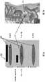
图7A及图7B图示用于体外测试本发明的组织仿体中的目标的一个示例。Figures 7A and 7B illustrate an example of targets used in in vitro testing of tissue phantoms of the present invention.
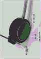
图8是附装至感测传感器(水听器)的能够产生弱聚焦束的一个例示性激发传感器的相片。Figure 8 is a photograph of an exemplary excitation sensor attached to a sensing sensor (hydrophone) capable of generating a weakly focused beam.
图9A、图9B及图9C示出来自使用一个例示性超声波装置的实验的代表性脉冲-回波数据。Figures 9A, 9B and 9C show representative pulse-echo data from experiments using an exemplary ultrasound device.
图10A是通过分析脉冲-回波数据以表示目标的位置而确定的值的图形表示。图10B是图10A中的值的色码表示。Figure 10A is a graphical representation of values determined by analyzing pulse-echo data to indicate the location of a target. Figure 10B is a color coded representation of the values in Figure 10A.
图11A是示例2中所概述的猪模型中的超声波的皮下施用的图。图11B提供在3cm及4cm深度中测量的正规化压力振幅。11A is a graph of subcutaneous administration of ultrasound in the porcine model outlined in Example 2. FIG. Figure 1 IB provides normalized pressure amplitudes measured in 3 cm and 4 cm depths.
图12A提供针对α=-4度沿颅-尾轴测量的代表性压力回波(kPa)对深度(g)。图12B提供针对α=-15度沿颅-尾轴测量的代表性压力回波(kPa)对深度(g)。Figure 12A provides representative pressure echoes (kPa) versus depth (g) measured along the cranio-caudal axis for α = -4 degrees. Figure 12B provides representative pressure echoes (kPa) versus depth (g) measured along the cranio-caudal axis for α = -15 degrees.
图13A是呈现依据相对于沿颅-尾轴的表面的角度(α,度)而变化的经记录压力回波的图。图13B是呈现依据相对于沿背-腹轴的表面的角度(α,度)而变化的经记录压力回波的图。13A is a graph presenting recorded pressure echoes as a function of angle (α, degrees) relative to the surface along the cranio-caudal axis. Figure 13B is a graph presenting recorded pressure echoes as a function of angle (α, degrees) relative to the surface along the dorsal-ventral axis.
图14A是用于结合覆迭的背-腹轴及颅-尾轴体内测试本发明的猪模型的图片。图14B是沿背-腹轴及颅-尾轴测量的最大压力回波的色码表示。Figure 14A is a picture of a porcine model used for in vivo testing of the invention in conjunction with the overlaid dorsal-ventral and cranial-caudal axes. Figure 14B is a color-coded representation of maximum pressure echoes measured along the dorsal-ventral and cranio-caudal axes.
具体实施方式Detailed ways
A.定义A. Definition
除非另有指定,否则如下文所陈述般定义本公开中所使用之术语。此外,如果本文中所使用的任何术语或符号未如下文所陈述般定义,则其应在此项技术中具有普通含义。Unless otherwise specified, terms used in this disclosure are defined as set forth below. Furthermore, if any term or symbol used herein is not defined as set forth below, it shall have its ordinary meaning in the art.
如本公开中所使用,除非本文中另有指示或上下文明显矛盾,否则在描述组件的上下文中单数冠词(诸如“一”、“一个”及“该”)及类似指涉物应被解释为涵盖单数及复数两者。除非本文中另有指示,否则本文中值范围的引述仅意欲于用作个别地引用落于该范围内的各单独值(包含该范围的上限及下限)的速记法,且各单独值如同其在本文中个别地引述般并入说明书中。除非本文中另有指示或上下文明显矛盾,否则可以任何适合次序执行本文中所描述的所有方法。除非另有规定,否则本文中所提供的任何及所有示例或例示性语言(例如,“诸如”)的使用仅意欲于更好地说明实施例且并未限制本公开的范畴。说明书中的语言不应被解释为将任何非主张组件指示为必不可少。As used in this disclosure, singular articles (such as "a," "an," and "the") and similar referents in the context of describing an element should be construed unless otherwise indicated herein or otherwise clearly contradicted by context. to cover both the singular and the plural. Recitation of ranges of values herein are merely intended to be used as a shorthand method of referring individually to each separate value falling within the range (including the upper and lower limits of the range), unless otherwise indicated herein, and each separate value is referred to herein as if it were individually recited. Individual references herein are incorporated into the specification. All methods described herein can be performed in any suitable order unless otherwise indicated herein or otherwise clearly contradicted by context. The use of any and all examples, or exemplary language (eg, "such as") provided herein, is intended merely to better illuminate the embodiments and does not limit the scope of the disclosure unless otherwise stated. No language in the specification should be construed as indicating any non-claimed component as essential.
术语“体内”是指发生在活体内的过程。The term "in vivo" refers to processes that occur within a living body.
术语“原位”是指发生在原始、天然或既有部位或位置中的过程。The term "in situ" refers to a process that occurs in an original, native or established site or location.
术语“非原位”是指发生在外部、异地或远离天然位置的过程。The term "ex situ" refers to a process that occurs externally, ex situ, or away from a natural location.
术语“目标”在用于本说明书中时是指原位存在于生物结构内、存在于受试者(其位置可使用本发明的装置及方法来确定)内的对象。例示性目标包含肾结石、胆结石、组织钙化区域、钙化或其他生物矿化区域、声阻抗完全不同于组织的异物及造影剂(靶向或非靶向)的累积等。The term "target" as used in this specification refers to an object that exists in situ within a biological structure, within a subject, the location of which can be determined using the devices and methods of the present invention. Exemplary targets include kidney stones, gallstones, calcified areas of tissue, areas of calcification or other biomineralization, foreign bodies with an acoustic impedance substantially different from tissue, accumulations of contrast agents (targeted or non-targeted), and the like.
术语“近似准直”或“弱聚焦”是指其中各x及y(在x及y的规定范围内)处的非降额瞬时压力自跨声波照射体积内的z值范围对应于x及y的非降额压力偏离小于规定上限的能量状态,其中z是法向于孔径面的坐标轴。The term "approximately collimated" or "weakly focused" means one in which the non-derated instantaneous pressure at each x and y (within the specified ranges of x and y) corresponds to x and y from a range of z values across the insonified volume The energy state where the non-derated pressure deviates less than the specified upper limit, where z is the coordinate axis normal to the aperture plane.
B.其他解译惯例B. Other interpretation conventions
本文中所引述的范围应被理解为范围内的所有值(包含所引述端点)的速记。例如,1至50的范围应被理解为包含来自由下列组成的群组的任何数字、数字组合或子范围:1、2、3、4、5、6、7、8、9、10、11、12、13、14、15、16、17、18、19、20、21、22、23、24、25、26、27、28、29、30、31、32、33、34、35、36、37、38、39、40、41、42、43、44、45、46、47、48、49及50。Ranges recited herein are to be understood as shorthand for all values within the range, inclusive of the recited endpoints. For example, a range of 1 to 50 should be understood to include any number, combination of numbers, or subrange from the group consisting of: 1, 2, 3, 4, 5, 6, 7, 8, 9, 10, 11 , 12, 13, 14, 15, 16, 17, 18, 19, 20, 21, 22, 23, 24, 25, 26, 27, 28, 29, 30, 31, 32, 33, 34, 35, 36 , 37, 38, 39, 40, 41, 42, 43, 44, 45, 46, 47, 48, 49 and 50.
当本发明的方法包括多个步骤时,除非另有指示,否则不要求以特定次序执行多个步骤。本公开并未直接或间接要求特定次序。When a method of the invention includes multiple steps, the steps do not require that they be performed in a particular order, unless otherwise indicated. This disclosure does not require, directly or indirectly, a particular order.
C.用于原位定位目标的装置及系统C. Apparatus and systems for locating targets in situ
本发明是关于一种与先前技术中所使用的其他装置相比使用宽束、低频率(<1MHZ)超声波的基本上新颖装置,其经由经改进信号对背景比而赋予本发明技术优点。相较于多数超声波成像技术,其在实施方面也是根本上不同,因为其检测目标(诸如肾结石、胆结石、声阻抗完全不同于组织的异物及造影剂(靶向或非靶向)的累积等)且映像目标的位置而不产生影像。相当于螺栓探测器,这允许较低使用技术水平。The present invention is concerned with a substantially novel device using broad beam, low frequency (<1 MHZ) ultrasound compared to other devices used in the prior art, which confers the technical advantages of the present invention via an improved signal-to-background ratio. It is also fundamentally different in its implementation compared to most ultrasound imaging techniques, as it detects targets such as kidney stones, gallstones, foreign bodies with an acoustic impedance completely different from tissue, and accumulation of contrast agents (targeted or not) etc.) and map the position of the target without producing an image. Equivalent to a bolt finder, this allows for lower skill levels of use.
相比于被定义为产生需要将影像重新平移至受试者上的额外步骤的非原位表示的成像,映射在本文中被定义为原位检测目标而不产生及解译该影像。成像与映像之间的差异可通过指定在映像的情况下来自目标的声音(回波)的反射比对象或检测器的大小更分散来阐明,且因此需要多个读数,自此出现与最接近于肾结石的表面位置同心的图案。In contrast to imaging, which is defined as producing an ex situ representation requiring an additional step of re-translating the image onto the subject, mapping is defined herein as detecting objects in situ without producing and interpreting the image. The difference between imaging and reflection can be clarified by specifying that in the case of imaging the reflection of sound (echoes) from the target is more diffuse than the size of the object or detector, and thus requires multiple readings, since the closest A pattern concentric to the superficial location of the kidney stone.
图1中图示弱聚焦超声波束的一般概念。抵靠表面102保持激发传感器101。术语“弱聚焦超声波束”是指其中体积103内的非降额瞬时压力是在自标称值的规定变化内的状态。The general concept of a weakly focused ultrasound beam is illustrated in FIG. 1 . The
在一些实施例中,体积远离孔径至少3cm开始且延伸至少4cm。在一些实施例中,体积远离孔径至少2cm、2.5cm、3cm、3.5cm、4cm、4.5cm、5cm、5.5cm、6cm、6.5cm、7cm、7.5cm、8cm、8.5cm、9cm、9.5cm、10cm、10.5cm、11cm、11.5cm、12cm、12.5cm、13cm、13.5cm、14cm、14.5cm、15cm、15.5cm、16cm、16.5cm、17cm、17.5cm、18cm、18.5cm、19cm或20cm开始且远离孔径延伸至少2cm、2.5cm、3cm、3.5cm、4cm、4.5cm、5cm、5.5cm、6cm、6.5cm、7cm、7.5cm、8cm、8.5cm、9cm、9.5cm或10cm。在一些实施例中,体积远离孔径至少4cm、4.5cm、5cm、5.5cm、6cm、6.5cm、7cm、7.5cm、8cm、8.5cm、9cm、9.5cm、10cm、10.5cm、11cm、11.5cm、12cm、12.5cm、13cm、13.5cm、14cm、14.5cm、15cm、15.5cm、16cm、16.5cm、17cm、17.5cm、18cm、18.5cm、19cm、19.5cm或20cm终止。In some embodiments, the volume begins at least 3 cm away from the pore diameter and extends at least 4 cm. In some embodiments, the volume is at least 2 cm, 2.5 cm, 3 cm, 3.5 cm, 4 cm, 4.5 cm, 5 cm, 5.5 cm, 6 cm, 6.5 cm, 7 cm, 7.5 cm, 8 cm, 8.5 cm, 9 cm, 9.5 cm, 10cm, 10.5cm, 11cm, 11.5cm, 12cm, 12.5cm, 13cm, 13.5cm, 14cm, 14.5cm, 15cm, 15.5cm, 16cm, 16.5cm, 17cm, 17.5cm, 18cm, 18.5cm, 19cm or 20cm start and Extends at least 2cm, 2.5cm, 3cm, 3.5cm, 4cm, 4.5cm, 5cm, 5.5cm, 6cm, 6.5cm, 7cm, 7.5cm, 8cm, 8.5cm, 9cm, 9.5cm or 10cm away from the aperture. In some embodiments, the volume is at least 4 cm, 4.5 cm, 5 cm, 5.5 cm, 6 cm, 6.5 cm, 7 cm, 7.5 cm, 8 cm, 8.5 cm, 9 cm, 9.5 cm, 10 cm, 10.5 cm, 11 cm, 11.5 cm, 12cm, 12.5cm, 13cm, 13.5cm, 14cm, 14.5cm, 15cm, 15.5cm, 16cm, 16.5cm, 17cm, 17.5cm, 18cm, 18.5cm, 19cm, 19.5cm or 20cm stop.
在一些实施例中,各x及y(在x及y的规定范围内)处的非降额瞬时压力自跨开始于z=3cm的z值范围对应于体积内的x及y的非降额压力偏离小于6dB,其中z是法向于孔径面的坐标轴。(图1)In some embodiments, the non-derating instantaneous pressure at each x and y (within the specified ranges of x and y) corresponds to the non-derating of x and y in the volume from the range of z values starting at z = 3 cm The pressure deviation is less than 6dB, where z is the coordinate axis normal to the aperture face. (figure 1)
在一些实施例中,z值是在3cm与7cm之间的范围中。在一些实施例中,z值是在3cm与8cm之间的范围中。在一些实施例中,z值是在3cm与9cm之间的范围中。在一些实施例中,z值是在3cm与10cm之间的范围中。在一些实施例中,z值是在3cm与11cm之间、在3cm与12cm之间、在3cm与13cm之间、在3cm与14cm之间、在3cm与15cm之间、在3cm与16cm之间、在3cm与17cm之间、在3cm与18cm之间、在3cm与19cm之间、在3cm与20cm之间、在4cm与8cm之间、在4cm与9cm之间、在4cm与10cm之间、4cm与11cm之间、在4cm与12cm之间、在4cm与13cm之间、在4cm与14cm之间、在4cm与15cm之间、在4cm与16cm之间、在4cm与17cm之间、在4cm与18cm之间、在4cm与19cm之间、在4cm与20cm之间、在5cm与9cm之间、在5cm与10cm之间、在5cm与11cm之间、在5cm与12cm之间、在5cm与13cm之间、在5cm与14cm之间、在5cm与15cm之间、在5cm与16cm之间、在5cm与17cm之间、在5cm与18cm之间、在5cm与19cm之间、在5cm与20cm之间、在6cm与10cm之间、在6cm与11cm之间、在6cm与12cm之间、在6cm与13cm之间、在6cm与14cm之间、在6cm与15cm之间、在6cm与16cm之间、在6cm与17cm之间、在6cm与18cm之间、在6cm与19cm之间、在6cm与20cm之间、在7cm与11cm之间、在7cm与12cm之间、在7cm与13cm之间、在7cm与14cm之间、在7cm与15cm之间、在7cm与16cm之间、在7cm与17cm之间、在7cm与18cm之间、在7cm与19cm之间、在7cm与20cm之间、在8cm与12cm之间、在8cm与13cm之间、在8cm与14cm之间、在8cm与15cm之间、在8cm与16cm之间、在8cm与17cm之间、在8cm与18cm之间、在8cm与19cm之间、在8cm与20cm之间、在9cm与13cm之间、在9cm与14cm之间、在9cm与15cm之间、在9cm与16cm之间、在9cm与17cm之间、在9cm与18cm之间、在9cm与19cm之间、在9cm与20cm之间、在10cm与14cm之间、在10cm与15cm之间、在10cm与16cm之间、在10cm与17cm之间、在10cm与18cm之间、在10cm与19cm之间、在10cm与20cm之间、在11cm与15cm之间、在11cm与16cm之间、在11cm与17cm之间、在11cm与18cm之间、在11cm与19cm之间或在11cm与20cm之间的范围中。In some embodiments, the z-value is in the range between 3 cm and 7 cm. In some embodiments, the z-value is in the range between 3 cm and 8 cm. In some embodiments, the z-value is in the range between 3 cm and 9 cm. In some embodiments, the z-value is in the range between 3 cm and 10 cm. In some embodiments, the z-value is between 3 cm and 11 cm, between 3 cm and 12 cm, between 3 cm and 13 cm, between 3 cm and 14 cm, between 3 cm and 15 cm, between 3 cm and 16 cm , between 3cm and 17cm, between 3cm and 18cm, between 3cm and 19cm, between 3cm and 20cm, between 4cm and 8cm, between 4cm and 9cm, between 4cm and 10cm, Between 4cm and 11cm, between 4cm and 12cm, between 4cm and 13cm, between 4cm and 14cm, between 4cm and 15cm, between 4cm and 16cm, between 4cm and 17cm, between 4cm Between 18cm, 4cm and 19cm, 4cm and 20cm, 5cm and 9cm, 5cm and 10cm, 5cm and 11cm, 5cm and 12cm, 5cm and Between 13cm, between 5cm and 14cm, between 5cm and 15cm, between 5cm and 16cm, between 5cm and 17cm, between 5cm and 18cm, between 5cm and 19cm, between 5cm and 20cm Between, between 6cm and 10cm, between 6cm and 11cm, between 6cm and 12cm, between 6cm and 13cm, between 6cm and 14cm, between 6cm and 15cm, between 6cm and 16cm between 6cm and 17cm, between 6cm and 18cm, between 6cm and 19cm, between 6cm and 20cm, between 7cm and 11cm, between 7cm and 12cm, between 7cm and 13cm , between 7cm and 14cm, between 7cm and 15cm, between 7cm and 16cm, between 7cm and 17cm, between 7cm and 18cm, between 7cm and 19cm, between 7cm and 20cm, Between 8cm and 12cm, between 8cm and 13cm, between 8cm and 14cm, between 8cm and 15cm, between 8cm and 16cm, between 8cm and 17cm, between 8cm and 18cm, between Between 8cm and 19cm, between 8cm and 20cm, between 9cm and 13cm, between 9cm and 14cm, between 9cm and 15cm, between 9cm and 16cm, between 9cm and 17cm, between 9cm between 18cm, between 9cm and 19cm, between 9cm and 20cm, between 10cm and 14cm, between 10cm and 15cm, between 10cm and 16cm, between 10cm and 17cm, between 10cm and Between 18cm, between 10cm and 19cm, between 10cm and 20cm, between 11cm and 15cm, between 11cm and 16cm, between 11cm and 17cm, between 11cm and 18cm, between 11cm and 19cm Between or in the range between 11cm and 20cm.
在一些实施例中,x及y值是在0cm与至少0.5cm、1cm、1.5cm、2cm、2.5cm、3cm、3.5cm、4cm、4.5cm、5cm、5.5cm、6cm、6.5cm、7cm、7.5cm、8cm、8.5cm、9cm或10cm之间的范围中。在一些实施例中,x及y值是在0cm与小于3cm、4cm、5cm、6cm、7cm、8cm、9cm、10cm、11cm、12cm、13cm、14cm、15cm、16cm、17cm、18cm、19cm或20cm之间的范围中。In some embodiments, the x and y values are between 0 cm and at least 0.5 cm, 1 cm, 1.5 cm, 2 cm, 2.5 cm, 3 cm, 3.5 cm, 4 cm, 4.5 cm, 5 cm, 5.5 cm, 6 cm, 6.5 cm, 7 cm, In the range between 7.5cm, 8cm, 8.5cm, 9cm or 10cm. In some embodiments, the x and y values are between 0 cm and less than 3 cm, 4 cm, 5 cm, 6 cm, 7 cm, 8 cm, 9 cm, 10 cm, 11 cm, 12 cm, 13 cm, 14 cm, 15 cm, 16 cm, 17 cm, 18 cm, 19 cm, or 20 cm in the range between.
在一些实施例中,各x及y(在x及y的规定范围内)处的非降额瞬时压力自跨z值的范围对应于体积内的x及y的非降额压力偏离小于4.5dB、5dB、5.5dB、6dB、6.5dB、7dB、7.5dB、8dB、8.5dB、9dB、9.5dB、10dB、10.5dB、11dB、11.5dB、12dB、13dB、13.5dB、14dB、14.5dB、15dB、15.5dB、16dB、16.5dB、17dB、17.5dB、18dB、18.5dB、19dB、19.5dB或20dB。In some embodiments, the non-derated instantaneous pressure at each x and y (within the specified ranges of x and y) deviates by less than 4.5 dB from the non-derated pressure corresponding to x and y within the volume across the range of z values , 5dB, 5.5dB, 6dB, 6.5dB, 7dB, 7.5dB, 8dB, 8.5dB, 9dB, 9.5dB, 10dB, 10.5dB, 11dB, 11.5dB, 12dB, 13dB, 13.5dB, 14dB, 14.5dB, 15dB, 15.5dB, 16dB, 16.5dB, 17dB, 17.5dB, 18dB, 18.5dB, 19dB, 19.5dB or 20dB.
与直觉相反的是,本发明进一步依赖于使用较低频率声波(即,子MHz频率),其通过减少来自周围组织(背景)的反射而减小空间分辨率(根据衍射限制,500kHz将具有最小3mm分辨率)(相较于用于成像超声波应用的频率)且改进检测来自目标(举例而言,诸如肾结石大小的对象、胆结石、声阻抗完全不同于组织的异物及造影剂(靶向或非靶向)的累积)的能力。此背景源自大小相当于成像技术中所使用的波长(f=5MHz至10MHz,λ=0.3mm)的细胞结构。散射的物理学是波长相依性;当散射对象的大小远小于波长时,散射的概率显著减小。Counterintuitively, the present invention further relies on the use of lower frequency acoustic waves (i.e., sub-MHz frequencies) which reduce spatial resolution by reducing reflections from surrounding tissue (background) (500 kHz would have a minimum 3 mm resolution) (compared to frequencies used for imaging ultrasound applications) and improved detection from targets (for example, objects the size of kidney stones, gallstones, foreign bodies with an acoustic impedance completely different from tissue, and contrast agents (targeted or non-targeted) accumulation). This background arises from cellular structures whose size corresponds to the wavelength used in the imaging technique (f = 5 MHz to 10 MHz, λ = 0.3 mm). The physics of scattering is wavelength-dependent; when the size of the scattering object is much smaller than the wavelength, the probability of scattering decreases significantly.
本发明的一些实施例依赖于使用具有在以下范围中的低频率的声波:100kHz至1MHz、200kHz至1MHz、300kHz至1MHz、400kHz至1MHz、500kHz至1MHz、600kHz至1MHz、100kHz至900kHz、200kHz至900kHz、300kHz至900kHz、400kHz至900kHz、500kHz至900kHz、600kHz至900kHz、100kHz至800kHz、200kHz至800kHz、300kHz至800kHz、400kHz至800kHz、500kHz至800kHz、600kHz至800kHz、100kHz至700kHz、200kHz至800kHz、300kHz至800kHz、400kHz至800kHz、500kHz至800kHz、600kHz至800kHz、100kHz至700kHz、200kHz至700kHz、300kHz至700kHz、400kHz至700kHz、400kHz至600kHz、500kHz至600kHz、100kHz至600kHz、200kHz至600kHz、300kHz至600kHz、400kHz至600kHz、500kHz至600kHz或550kHz至600kHz。Some embodiments of the invention rely on the use of sound waves having low frequencies in the following ranges: 100 kHz to 1 MHz, 200 kHz to 1 MHz, 300 kHz to 1 MHz, 400 kHz to 1 MHz, 500 kHz to 1 MHz, 600 kHz to 1 MHz, 100 kHz to 900 kHz, 200 kHz to 900kHz, 300kHz to 900kHz, 400kHz to 900kHz, 500kHz to 900kHz, 600kHz to 900kHz, 100kHz to 800kHz, 200kHz to 800kHz, 300kHz to 800kHz, 400kHz to 800kHz, 500kHz to 800kHz, 600kHz to 800kHz, 200kHz to 800kHz to 800kHz, 300kHz to 800kHz, 400kHz to 800kHz, 500kHz to 800kHz, 600kHz to 800kHz, 100kHz to 700kHz, 200kHz to 700kHz, 300kHz to 700kHz, 400kHz to 700kHz, 400kHz to 600kHz, 500kHz to 600kHz, 600kHz to 200kHz , 300kHz to 600kHz, 400kHz to 600kHz, 500kHz to 600kHz, or 550kHz to 600kHz.
在一些实施例中,自激发传感器发射的声脉冲包括具有一个或多个频率的声波。在一些实施例中,自传感器发射的声脉冲包括具有一个或多个振幅的声波。In some embodiments, the acoustic pulses emitted from the excitation sensor include acoustic waves having one or more frequencies. In some embodiments, the acoustic pulses emitted from the sensor include acoustic waves having one or more amplitudes.
由于在本发明中所使用的声波具有远低于由典型成像超声波应用所使用的声波的频率的频率,故本发明中所公开的装置及系统提供较低空间分辨率。当使用方程式[1](即,ΔR=λF)计算分辨率时,λ是声波的波长且F是声系统的光圈值,由低频率波提供的分辨率大于0.3mm。在一些实施例中,分辨率(ΔR)大于0.4mm、大于0.5mm、大于0.6mm、大于0.7mm、大于0.8mm、大于0.9mm、大于1mm、大于2mm、大于2.5mm、大于3mm、大于5mm、大于10mm、大于15mm、大于20mm、大于23mm、大于25mm或大于30mm。Since the acoustic waves used in the present invention have frequencies much lower than those used by typical imaging ultrasound applications, the devices and systems disclosed in the present invention provide lower spatial resolution. When calculating resolution using equation [1] (ie, ΔR=λF), λ being the wavelength of the acoustic wave and F being the f-stop of the acoustic system, the resolution provided by low frequency waves is greater than 0.3mm. In some embodiments, the resolution (ΔR) is greater than 0.4 mm, greater than 0.5 mm, greater than 0.6 mm, greater than 0.7 mm, greater than 0.8 mm, greater than 0.9 mm, greater than 1 mm, greater than 2 mm, greater than 2.5 mm, greater than 3 mm, greater than 5 mm , greater than 10mm, greater than 15mm, greater than 20mm, greater than 23mm, greater than 25mm or greater than 30mm.
D.用于原位定位目标的方法D. Methods for In Situ Locating Targets
在本发明的一些实施例中,超声波装置放置于被怀疑具有目标(例如,肾结石、胆结石、组织钙化区域、声阻抗完全不同于组织的异物及造影剂(靶向或非靶向)的累积等)的人类或动物受试者的躯干的表面上。该装置发送声脉冲,且接着接收反射(回波)。记录在如自脉冲的起点测量的特定时间窗口内此经反射信号的振幅。可使用一组位置的反射的振幅以通过整合至该装置的内部计算机或通过具有足够精熟度的用户建构映图,这允许确定(1)待确认目标(例如,肾结石)的存在/不存在及(2)待以足够准确度定位的目标的位置使得该装置可与目标原位对准。最后,可针对同心分布分析映图的轮廓,从而导致目标的更精确定位。In some embodiments of the invention, ultrasound devices are placed in areas suspected of having targets (e.g., kidney stones, gallstones, areas of tissue calcification, foreign bodies with an acoustic impedance completely different from tissue, and contrast agents (targeted or non-targeted). accumulation, etc.) on the surface of the torso of a human or animal subject. The device sends sound pulses and then receives reflections (echoes). The amplitude of this reflected signal is recorded over a specific time window as measured from the start of the pulse. The amplitude of the reflection for a set of locations can be used to construct a map, either by an internal computer integrated into the device or by a user with sufficient sophistication, which allows for the determination of (1) the presence/absence of a target to be identified (e.g., a kidney stone) There is and (2) the location of the target to be located with sufficient accuracy such that the device can be aligned in situ with the target. Finally, the contours of the maps can be analyzed for concentric distributions, leading to more precise localization of objects.
图2A至图2B中图示使用弱聚焦超声波束来定位目标的一般概念。图2A示出在其沿躯干200的表面平移时产生弱聚焦超声波束的激发传感器202。圆柱形轮廓(即,体积或声波照射体积)204内的非降额瞬时压力是在自标称值的规定变化内。由激发传感器产生的声波的峰值是在中心。强度分布的宽度可被定义为半峰全宽(FWHM)。在一些实施例中,自激发传感器发射的超声波能量主要限定于具有在下列范围中的横向宽度的声波照射体积:1cm至4cm、1cm至4.5cm、1cm至5cm、1cm至6cm、1cm至10cm、0.5cm至4cm、0.5cm至5cm、0.5cm至6cm、0.6cm至7cm、1.5cm至5cm、1.5cm至6cm、1.5cm至7cm或2cm至7cm。在一些实施例中,自传感器发射之大于70%、80%、90%、95%、98%或99%超声波能量限定于具有在下列范围中的横向宽度的声波照射体积:1cm至4cm、1cm至4.5cm、1cm至5cm、1cm至6cm、1cm至10cm、0.5cm至4cm、0.5cm至5cm、0.5cm至6cm、0.6cm至7cm、1.5cm至5cm、1.5cm至6cm、1.5cm至7cm或2cm至7cm。The general concept of using a weakly focused ultrasound beam to locate a target is illustrated in FIGS. 2A-2B . FIG. 2A shows
回波是自定位于一深度范围内的深度(相对于孔径面)处的目标对象201产生,其中弱聚焦束的能量高于规定最小值。可通过分析与多个传感器位置及/或角度相关联的回波而产生分布203。Echoes are generated from a
使用本发明的方法原位检测及定位的目标对象201可小于2.3cm。在一些实施例中,使用本发明的方法原位检测及定位的目标对象201小于0.5cm、1cm、1.3cm、1.5cm、1.8cm、2cm、2.3cm、2.5cm、2.8cm、3cm、3.3cm、3.5cm、3.8cm、4cm、4.3cm、4.5cm、4.8cm或5cm。The
用户可沿包含目标的受试者的表面(例如,哺乳类受试者的躯干的表面)移动传感器202。此装置的横向平移将产生照射目标201的入射波的强度改变。在理想情况下,水听器接受角与来自传感器202的经传输信号同心,或其可为离心,从而导致小定位差。A user may move
图3中进一步图示用于原位检测目标的装置的一个例示性使用。传感器301跨可能含有所关注回波对象305的内部解剖区域外部的解剖区域传送具有宽度(FWHM)及深度的超声波能量脉冲310。在一些实施例中,目标选自由肾结石、胆结石、组织钙化区域、钙化或其他生物矿化区域、声阻抗完全不同于天然组织的异物及造影剂的累积组成的群组。在一些实施例中,造影剂是具有对组织、细胞、器官、异物、肾结石、胆结石或动脉粥样化斑块的特定亲和性的材料。在一些实施例中,造影剂是微气泡。可在检测目标之前将微气泡施予受试者。One exemplary use of the apparatus for in situ detection of objects is further illustrated in FIG. 3 .
对于具有有效直径phi[T]的目标,针对FWHM>phi[T],由声治疗总成内的感测传感器(例如,水听器)302、303、304检测来自各循序反射的回波。在一些实施例中,一个传感器既用作感测传感器又用作激发传感器。自传感器传输复数个超声波束306且当该传感器循序移动至下一位置308时接收复数个回波307。由于较长波长及其相关联空间分辨率减小,经反射信号(回波307)将具有更广分布(称为点扩散函数或PSF)。然而,PSF仍与目标的中心同心使得映射此强度轮廓允许以高于单次测量可能具有的精度确定目标的位置。如图中所图示,各脉冲-回波测量内的循序回波幅度309的集成(ensemble)形成与目标305(即,目标)的位置311(即,形心)同心的分布310。在一些实施例中,分布是如图3中所呈现的高斯分布310或重叠高斯分布或艾瑞函数分布。For a target with an effective diameter phi[T], for FWHM>phi[T], the echoes from each sequential reflection are detected by sensing sensors (eg, hydrophones) 302, 303, 304 within the acoustic therapy assembly. In some embodiments, one sensor acts as both a sensing sensor and an excitation sensor. Ultrasonic beams 306 are transmitted from the sensor and echoes 307 are received as the sensor moves sequentially to a next location 308 . Due to longer wavelengths and their associated reduced spatial resolution, the reflected signal (echo 307) will have a wider distribution (called the point spread function or PSF). However, the PSF is still concentric with the center of the target so that mapping this intensity profile allows the position of the target to be determined with higher precision than possible with a single measurement. As illustrated in the figure, the ensemble of sequential echo magnitudes 309 within each pulse-echo measurement forms a distribution 310 that is concentric with the location 311 (ie, centroid) of the target 305 (ie, the target). In some embodiments, the distribution is a Gaussian distribution 310 as presented in FIG. 3 or an overlapping Gaussian distribution or an Airy function distribution.
此集成分析方法及算法可在定位目标时比个别测量(其受限于广束宽度及治疗总成的定位与对准精度两者)更准确(与横向尺寸中的样本数目的平方根成比例)且此外适于经由回馈原位对准治疗总成及目标。This integrated analysis method and algorithm can be more accurate (proportional to the square root of the number of samples in the transverse dimension) in locating the target than individual measurements (which are limited by both the wide beam width and the positioning and alignment accuracy of the treatment assembly) And also suitable for in situ alignment of the therapy assembly and target via feedback.
在一些实施例中,由处理器分析由感测传感器接收的超声波束的经反射分量以计算目标的位置。在一些实施例中,处理器是包括激发传感器及/或感测传感器的检测装置的部件。在一些实施例中,处理器是单独计算装置的部件。在一些实施例中,处理器测量在通过激发传感器发射声脉冲与通过感测传感器接收声脉冲的经反射分量之间的时间延迟。可使用该时间延迟以确定目标相对于激发传感器或感测传感器的位置。有时,使用超声波束的经反射分量的振幅以确定目标的位置。In some embodiments, the reflected component of the ultrasound beam received by the sensing sensor is analyzed by the processor to calculate the position of the target. In some embodiments, the processor is a component of a detection device comprising an excitation sensor and/or a sense sensor. In some embodiments, the processor is part of a separate computing device. In some embodiments, the processor measures a time delay between transmitting the acoustic pulse by the exciting sensor and receiving the reflected component of the acoustic pulse by the sensing sensor. This time delay can be used to determine the position of the target relative to the excitation sensor or the sense sensor. Sometimes the amplitude of the reflected component of the ultrasound beam is used to determine the position of the target.
在一些实施例中,处理器将与目标的位置相关的信息发送至输出装置。在一些实施例中,输出装置是将与目标的位置相关的信息显示为文字、显示为声音或视觉信号或显示为影像的显示设备。在一些实施例中,输出装置产生与目标的位置相关的报告。在一些实施例中,处理器将与目标的位置相关的信息保存于存储装置中以供随后使用。In some embodiments, the processor sends information related to the location of the target to the output device. In some embodiments, the output device is a display device that displays information related to the location of the target as text, as audio or visual signals, or as images. In some embodiments, the output device generates a report related to the location of the target. In some embodiments, the processor saves information related to the location of the target in the storage device for later use.
在一些实施例中,处理器可分析经发射超声波能量脉冲的振幅及超声波能量脉冲的经接收、反射分量的振幅的变化。有时,使用经分析变化以确定目标或米氏散射体的位置及存在。In some embodiments, the processor may analyze changes in the amplitude of the transmitted pulse of ultrasonic energy and the amplitude of the received, reflected component of the pulse of ultrasonic energy. Sometimes the analyzed changes are used to determine the location and presence of targets or Mie scatterers.
E.用于对准传感器的系统及方法E. Systems and Methods for Aligning Sensors
在一些实施例中,用户可使用与目标的位置相关的信息以旋转或平移激发传感器以将其对准至目标以用于后续检测。在一些实施例中,将与目标的位置相关的信息发送至被配置为旋转或平移激发传感器以对准至目标以用于后续检测的装置。In some embodiments, the user may use the information about the target's location to rotate or translate the excitation sensor to align it to the target for subsequent detection. In some embodiments, information related to the location of the target is sent to a device configured to rotate or translate the excitation sensor for alignment to the target for subsequent detection.
在一些实施例中,用户可使用与目标的位置相关的信息以旋转或平移感测传感器以将其对准至目标以用于后续检测。在一些实施例中,将与目标的位置相关的信息发送至被配置为旋转或平移感测传感器以对准至目标以用于后续检测的装置。在一些实施例中,激发传感器可仅在其与目标对准时发射超声波能量脉冲。In some embodiments, the user may use the information about the location of the target to rotate or translate the sensing sensor to align it to the target for subsequent detection. In some embodiments, information related to the position of the target is sent to a device configured as a rotation or translation sensing sensor for alignment to the target for subsequent detection. In some embodiments, the excitation sensor may only emit pulses of ultrasonic energy when it is aligned with the target.
在一些实施例中,用户可使用与目标的位置相关的信息以旋转或平移治疗传感器以将其对准至目标以用于治疗。在一些实施例中,将与目标的位置相关的信息发送至被配置为旋转或平移治疗传感器以对准至目标以用于治疗的装置。在一些实施例中,感测传感器可仅在其与目标对准时接收回波。In some embodiments, the user may use information about the target's location to rotate or translate the therapy sensor to align it to the target for therapy. In some embodiments, information related to the location of the target is sent to a device configured to rotate or translate the therapy sensor for alignment to the target for therapy. In some embodiments, a sensing sensor may only receive echoes when it is aligned with a target.
在一些实施例中,治疗传感器发射具有足以使目标(诸如肾结石、胆结石、组织钙化区域、钙化或其他生物矿化区域、声阻抗完全不同于组织的异物、造影剂(靶向或非靶向)的累积)破裂的能量的束。在一些实施例中,目标涂布有微气泡。治疗传感器可发射能量以引起微气泡的孔蚀以释放足以分裂目标的能量。在一些实施例中,治疗传感器可仅在其与目标对准时发射具有高能量的束。In some embodiments, the therapeutic sensor emits a target (such as a kidney stone, a gallstone, a calcified area of tissue, a calcified or other biomineralized area, a foreign body with an acoustic impedance that is completely different from tissue, a contrast agent (targeted or non-targeted A beam of accumulated) rupture energy towards ). In some embodiments, the target is coated with microbubbles. The therapy sensor can emit energy to cause the cavitation of microbubbles to release enough energy to disintegrate the target. In some embodiments, the therapy sensor may only emit a beam with high energy when it is aligned with the target.
在一些实施例中,一个传感器既充当激发传感器又充当治疗传感器。在一些实施例中,一个传感器充当激发传感器、感测传感器及治疗传感器。在一些实施例中,一个传感器充当感测传感器及治疗传感器。In some embodiments, one sensor acts as both an excitation sensor and a therapy sensor. In some embodiments, one sensor acts as an excitation sensor, a sensing sensor, and a therapy sensor. In some embodiments, one sensor acts as both the sensing sensor and the therapy sensor.
图4概述使用低频率超声波进行目标检测的一个例示性方法。首先,激发传感器传输低频率超声波束(1)。在特定位置中,自目标反射低频率超声波束的分量。感测传感器(例如,水听器)接收自目标反射的回波(2)。处理器确定TOF(飞行时间)以窗口化(window)回波且使用此项技术中已知及/或本文中所描述的各种方法测量回波的幅度(3)。对用户显示幅度及/或存储幅度以供随后使用(4)。用户或机器可使束平移或转向以用于后续测量(5)。处理器可分析及映像幅度信息且确定经接收信号的形心(6)。可由用户或装置使用与形心相关的信息以使治疗总成转向或平移以与目标对准(7)。Figure 4 outlines an exemplary method for object detection using low frequency ultrasound. First, the excitation transducer transmits a low-frequency ultrasound beam (1). In a particular location, a component of the low frequency ultrasound beam is reflected from the target. A sensing sensor (eg a hydrophone) receives echoes reflected from the target (2). The processor determines the TOF (time of flight) to window the echoes and measure the amplitude of the echoes using various methods known in the art and/or described herein (3). The magnitude is displayed to the user and/or stored for later use (4). A user or machine can translate or steer the beam for subsequent measurements (5). The processor can analyze and map the magnitude information and determine the centroid of the received signal (6). The centroid-related information can be used by the user or the device to steer or translate the treatment assembly to align with the target (7).
图5A及图5B进一步提供概述使用低频率超声波的两个可能目标检测算法的流程图。图5A中所概述的第一方法涉及传输短脉冲501,接着由检测器进行一定周期的获取502。分析在获取周期期间获取的回波503例如以确定所有经反射信号的飞行时间。接着,针对所关注飞行时间窗口化经获取数据,记录经窗口化数据的优值的统计504,且存储值505。此循环可重复特定次数(N)508以考虑归因于呼吸的运动。自此测量集成,可针对经收集数据选择统计表示,对结果分级化506且接着对用户实时显示507结果。在此算法中,用户通过更改由经显示数据输出导引的适当坐标而找到适当对准。5A and 5B further provide flow charts outlining two possible object detection algorithms using low frequency ultrasound. The first method, outlined in Figure 5A, involves the transmission of a short pulse 501, followed by a certain period of acquisition 502 by the detector. The echoes 503 acquired during the acquisition period are analyzed eg to determine the time of flight of all reflected signals. The acquired data is then windowed for the time-of-flight of interest, statistics of the figure of merit of the windowed data are recorded 504 , and the values are stored 505 . This cycle may be repeated a certain number of times (N) 508 to account for motion due to respiration. From this measurement integration, a statistical representation can be selected for the collected data, the results graded 506 and then displayed 507 to the user in real time. In this algorithm, the user finds the proper alignment by altering the proper coordinates guided by the displayed data output.
图5B中所概述的第二方法类似于第一方法,但具有一个主要差异:在针对给定坐标处理且存储特定数目个循环之后,针对不同坐标值存储额外循环518。在更改坐标时,可存储针对给定坐标的经获取数据且比较514该经获取数据与针对不同坐标的经存储数据。此过程允许电子处理经收集数据的分布使得可确定515且对用户显示516分布的形心。The second method outlined in Figure 5B is similar to the first method, but with one major difference: after a certain number of cycles have been processed and stored for a given coordinate, additional cycles are stored 518 for different coordinate values. When changing coordinates, acquired data for a given coordinate may be stored and compared 514 to stored data for a different coordinate. This process allows electronic processing of the distribution of collected data so that the centroid of the distribution can be determined 515 and displayed 516 to the user.
F.本发明之优点F. Advantages of the present invention
图6提供使用表示先前技术的高频率超声波实时原位成像的躯干的2D截面图。垂直轴表示自皮肤或表面的深度,且水平尺寸表示正交于表面的尺寸。如此图中所图示的不良信噪比需要使用成像及图案辨识以区别特征且解译结构。其也需要由有经验的超声检查技师进行分析及解译,因为组织的细胞结构对超声波也极具反射性。在此特定示例中,超声检查技师将对象识别为肾结石601。Figure 6 provides a 2D cross-sectional view of the torso using high frequency ultrasound real-time in situ imaging representing the prior art. The vertical axis represents depth from the skin or surface, and the horizontal dimension represents the dimension normal to the surface. Poor signal-to-noise ratios as illustrated in this figure require the use of imaging and pattern recognition to distinguish features and interpret structures. It also needs to be analyzed and interpreted by an experienced sonographer because the cellular structure of the tissue is also very reflective to ultrasound waves. In this particular example, the sonographer identified the object as a
如本文中所图示,本发明允许在不使用单独成像系统或不使用解剖标志进行导航的情况下对准超声波束以用于治疗及诊疗的目的。成像技术可相当精确(例如,x射线CT),但如果接着经由解剖标志将经产生影像投射回至病患上(如常见做法)以便对准超声波治疗传感器与目标,则精度在窗口外直线下降。As illustrated herein, the present invention allows alignment of ultrasound beams for therapeutic and diagnostic purposes without the use of a separate imaging system or without the use of anatomical landmarks for navigation. Imaging techniques can be quite accurate (e.g. x-ray CT), but if the resulting image is then projected back onto the patient via anatomical landmarks (as is common practice) to align the ultrasound therapy transducer with the target, accuracy plummets outside the window .
此外,本发明示出:在选择促成降低背景噪声的较低频率方面存在竞争优势:较低频率既(1)更容易穿透软组织(较少吸收)从而允许更深检测,又(2)通过软组织更少程度地散射回朝向检测器。Furthermore, the present invention shows that there is a competitive advantage in selecting lower frequencies that result in reduced background noise: lower frequencies both (1) penetrate soft tissue more easily (less absorption) allowing deeper detection, and (2) pass through soft tissue Scatter to a lesser extent back towards the detector.
G.示例G. Example
下文是用于实施本发明的特定实施例的示例。示例仅出于图示性目的而提供,且并非意欲于以任何方式限制本发明的范畴。已努力确保关于所使用数字(例如,量、温度等)的准确度,但当然应允许某一实验误差及偏差。The following are examples of specific embodiments for implementing the invention. The examples are provided for illustrative purposes only and are not intended to limit the scope of the invention in any way. Efforts have been made to ensure accuracy with respect to numbers used (eg, amounts, temperature, etc.), but some experimental errors and deviations should, of course, be allowed for.
I.示例1:体外目标检测I. Example 1: In vitro target detection
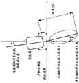
已使用图7A及图7B中所描述的组织仿体示范本发明。图7A是使用明胶基质填充8cm深的塑料玻璃室701的相片。明胶基质用作组织仿体。目标702悬浮于明胶基质中以表示所关注目标。虽然各种目标可用于示范,但鉴于铅的超声波能量反射性质,铅丸是适合选择。明胶上方的一层水辅助传感器头与明胶之间的耦合。图7B示出具有作为目标的5号(7.5mm直径)铅丸702的实验设置的俯视图。5x5 cm网格703已叠加于照片上。The invention has been demonstrated using the tissue phantom depicted in Figures 7A and 7B. Figure 7A is a photograph of a
如图8中示意性地示出,超声波传感器801(称为主要传感器)被配置于外壳802中。主要传感器并入能够由独立运算线性放大器非相干地驱动的多个组件,使得由主要传感器中的作用组件发射的声能量波相长及相消地干涉以产生弱聚焦束,在此情况下是近似圆柱形声能量束,有时称为准直束。主要传感器可包括激发传感器及治疗传感器。主要传感器也可包括既可充当激发传感器又可充当治疗传感器的一个传感器。As shown schematically in FIG. 8 , an ultrasonic sensor 801 (referred to as a primary sensor) is arranged in a housing 802 . The primary sensor incorporates multiple components that can be incoherently driven by independent operational linear amplifiers such that the waves of acoustic energy emitted by the active components in the primary sensor interfere constructively and destructively to produce a weakly focused beam, in this case the A nearly cylindrical beam of acoustic energy, sometimes called a collimated beam. Primary sensors may include excitation sensors and therapy sensors. Primary sensors can also include one sensor that can act as both an excitation sensor and a therapy sensor.
第二传感器(称为感测传感器803)与外壳802中的激发传感器并排定位。在对准主要传感器801的作用区域及感测传感器803的作用区域的情况下,在脉冲起始于主要传感器面处与回波到达于感测传感器处之间流逝的时间是近似回波之飞行时间(δt),且可通过下列方程式而与传感器-水听器与对象之间的总距离(δx)相关:A second sensor (referred to as sense sensor 803 ) is positioned alongside the excitation sensor in housing 802 . With the active area of the main sensor 801 and the active area of the sense sensor 803 aligned, the time elapsed between the initiation of the pulse at the main sensor face and the arrival of the echo at the sense sensor is approximately the flight of the echo time (δt), and can be related to the total distance (δx) between the sensor-hydrophone and the object by the following equation:
δx=(c·δt)/2 方程式[2]δx=(c·δt)/2 Equation [2]
其中c是声音在基质中的速度。外壳802、主要传感器801及感测传感器803共同组成治疗头总成804。where c is the speed of sound in the matrix. The shell 802 , the main sensor 801 and the sensing sensor 803 together form a treatment head assembly 804 .
治疗头总成804定位于明胶基质上方且在x及y两者上以1cm增量跨5x5 cm网格703扫描。接着针对振幅分析且绘制所得脉冲-回波数据。The treatment tip assembly 804 was positioned over the gelatin matrix and scanned across a
经发射信号是小数目个超声波脉冲(5次循环,580kHz,1.1MPa)。此处所使用的目标是铅拟饵,其是稍微非对称的。取决于肾结石组合物,预期来自此目标的信号反射的强度比天然肾结石的强度高2至4倍(下文比较反射系数)。然而,这可通过转至更高传输压力而予以补偿。The transmitted signal is a small number of ultrasound pulses (5 cycles, 580 kHz, 1.1 MPa). The target used here is a lead lure, which is slightly asymmetrical. Depending on the kidney stone composition, the intensity of the signal reflection from this target is expected to be 2 to 4 times higher than that of natural kidney stones (compare reflection coefficients below). However, this can be compensated by going to a higher delivery pressure.
跨网格分布的轮廓回波的形状(PSF,上文所示出)是归因于来自目标处的反射的干涉图案与检测几何结构的组合。尽管上述分布的峰值是在中心,但分布可归因于由目标产生的波干涉图案的物理学(其大小相当于声波的波长)而更复杂。The shape of the profile echo distributed across the grid (PSF, shown above) is due to the combination of the interference pattern from the reflection at the target and the detection geometry. Although the peak of the distribution described above is at the center, the distribution can be more complex due to the physics of the wave interference pattern produced by the target, whose magnitude is equivalent to the wavelength of the sound wave.
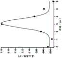
图9A至图9C中重现代表性脉冲-回波数据。在每一情况下,以t=20微秒示出脉冲接通时间。感测传感器迹线示出来自束的路径内的反射表面的回波。以约t=140微秒,来自室701的壁及底面的回波开始到达感测传感器803。图9A示出表示目标的完全错失的回波的迹线。图9B示出表示来自目标的掠(部分)反射的回波的迹线。图9C示出表示至目标的直接命中的回波的迹线。Representative pulse-echo data are reproduced in Figures 9A-9C. In each case, the pulse on-time is shown at t=20 microseconds. The sensing sensor trace shows echoes from reflective surfaces within the path of the beam. At approximately t=140 microseconds, echoes from the walls and floor of the
1.4ms至3.4ms的窗口内的声回波的最大振幅在图10A中被绘制为依据位置而变化。尽管用于反射的点扩散函数比此处所呈现的复杂,但可使用对称函数(诸如高斯分布)以估计分布的形心(与光学类似,其中出于寻找形心的目的,可将艾薇分布近似计算为高斯分布)。在此特定示例中,来自回波的循序数据拟合于包含定位形心(x0,y0)的参数的2D高斯分布。这是凭借以下认知来完成:回波声波(i(x))的分布通过由传输器产生的高斯束强力确定。尽管未先验计算模糊函数的确切函数形式,但高斯的使用与对模糊函数成为传输束宽度中的高斯分布的主要贡献一致。如图10B中所示出,将最大振幅值的数组拟合于2D高斯分布导致分布的形心的估计且因此导致目标相对于表面的位置;拟合估计形心在“0cm”正方形的中心的0.2cm内,其在此实验的实验误差内。The maximum amplitude of the acoustic echo within the window of 1.4 ms to 3.4 ms is plotted as a function of position in FIG. 10A . Although the point spread function for reflection is more complex than presented here, a symmetric function such as a Gaussian distribution can be used to estimate the centroid of the distribution (similar to optics where for the purpose of finding the centroid the Ivy distribution can be Approximately calculated as a Gaussian distribution). In this particular example, the sequential data from the echoes are fitted to a 2D Gaussian distribution containing parameters to locate the centroid (x0, y0). This is done with the knowledge that the distribution of echo acoustic waves (i(x)) is strongly determined by the Gaussian beam intensity generated by the transmitter. Although the exact functional form of the ambiguity function was not calculated a priori, the use of a Gaussian is consistent with a major contribution to the ambiguity function being a Gaussian distribution in the transmitted beam width. As shown in FIG. 10B , fitting an array of maximum amplitude values to a 2D Gaussian distribution leads to an estimate of the centroid of the distribution and thus the location of the target relative to the surface; the fit estimates the centroid at the center of the "0 cm" square. Within 0.2 cm, which is within the experimental error of this experiment.
II.示例2:体内目标检测II. Example 2: In vivo object detection
已在植入有结石的30kg活猪模型(图14A)中进一步示范本发明,如在R.F.Paterson等人的Percutaneous stone implantation in the pig kidney:a newanimal model for lithotripsy research,J.Endourol,16:8,543–547,(2002)中所描述。The invention has been further demonstrated in a 30 kg live pig model implanted with stones (Figure 14A), as in R.F. Paterson et al., Percutaneous stone implantation in the pig kidney: a new animal model for lithotripsy research, J. Endourol, 16:8, 543 –547, (2002) described.
具体言之,使用导管将4mm半胱氨酸肾结石插入于活猪的右输尿管的近端1/3中。使用诊断超声波将输尿管的深度验证为在皮肤下方近似3.5±0.5cm处以可视化插入至输尿管中的导管鞘的深度。接着在开始回波定位之前缩回鞘。Specifically, a 4 mm cysteine nephrolith was inserted in the proximal 1/3 of the right ureter of live pigs using a catheter. The depth of the ureter was verified to be approximately 3.5 ± 0.5 cm below the skin using diagnostic ultrasound to visualize the depth of the introducer sheath inserted into the ureter. The sheath is then retracted before beginning echolocation.
如图11A中所图示,在厚层中使用声耦合凝胶(Aquasonic)以耦合装置的传感器及水听器两者同时沿各轴旋转,此产生在1mm与5mm之间的自表面的额外偏离。使用以75W电功率、580kHz的频率驱动的平面25mm正方形传感器传输10微秒持续时间脉冲。图11A中提供用于其中传感器被保持于角度α的皮下超声波传输的模型,其中超声波压力(体积)的6dB等压表面被呈现为虚线椭圆体。所得体内声轴(β)可不同于α。Acoustic coupling gel (Aquasonic) was used in a thick layer to couple both the sensor and the hydrophone of the device while rotating along each axis as illustrated in FIG. Deviate. 10 microsecond duration pulses were transmitted using a planar 25mm square transducer driven at 75W electrical power at a frequency of 580kHz. A model for subcutaneous ultrasound transmission in which the transducer is held at angle α is provided in FIG. 11A , where the 6 dB isobaric surface of the ultrasound pressure (volume) is presented as a dashed ellipsoid. The resulting in vivo acoustic axis (β) may differ from α.
以自皮肤的3cm至4cm深度递送的皮下压力是在1MPa与1.1MPa之间,如由脱气水箱中的水听器所验证。使用脱气水箱中的水听器以3cm及4cm轮廓测量自以580kHz驱动的13mm宽正方形传感器的束深度。图11B中提供以3cm深度(空心圆)或以4cm深度(空心矩形)测量的压力振幅。The subcutaneous pressure delivered at a depth of 3 cm to 4 cm from the skin was between 1 MPa and 1.1 MPa as verified by hydrophones in a degassed water tank. Beam depth from a 13 mm wide square transducer driven at 580 kHz was measured at 3 cm and 4 cm profiles using a hydrophone in a degassed water tank. Pressure amplitudes measured at a depth of 3 cm (open circles) or at a depth of 4 cm (open rectangles) are provided in FIG. 11B .
电触发器经记录以计算经反射回波的飞行时间。使用安装针水听器(Y104,来自Sonic Concepts,580kHz下的近似6V/Mpa传递函数)与10x增益前置放大器(SRS 983)记录回波。使用具有0.1度准确度的倾斜仪(Johnson Level)以测量相对于皮肤表面的角度。Electrical triggers are recorded to calculate the time-of-flight of reflected echoes. Echoes were recorded using a pin hydrophone (Y104 from Sonic Concepts, approximately 6V/Mpa transfer function at 580kHz) with a 10x gain preamplifier (SRS 983). An inclinometer (Johnson Level) with 0.1 degree accuracy was used to measure the angle relative to the skin surface.
图12A及图12B提供沿颅-尾轴针对α=-4度(图12A)及α=-15度(图12B)测量的代表性压力回波(kPa)对自皮肤的深度(y)。使用声音的近似覆盖速(1500m/s)将自经记录压力波的飞行时间转换为深度,且因此表示近似深度。经记录压力回波也被呈现为依据相对于沿两个轴:颅-尾轴(图13A)及背-腹轴(图13B)的表面的角度(α,度)而变化。Figures 12A and 12B provide representative pressure echoes (kPa) versus depth from the skin (y) measured along the cranio-caudal axis for a = -4 degrees (Figure 12A) and a = -15 degrees (Figure 12B). The time-of-flight from the recorded pressure wave was converted to depth using the approximate velocity of coverage of the sound (1500 m/s), and thus represents the approximate depth. Recorded pressure echoes were also presented as a function of angle (α, degrees) relative to the surface along two axes: the cranio-caudal axis (Figure 13A) and the dorsal-ventral axis (Figure 13B).
针对相对于皮肤的法线的各角度一式三份地记录压力回波(例如,图12A/B及图13A/B),以改进呼吸期间的取样。经接收数据经窗口化至26μs至66μs之间的往返飞行时间,此对应于2cm至5cm的深度范围。经窗口化数据的最大值是使用其伴随测量角度进行记录。在图14B中,最大值接着被分级化成三级:0kPa至90kPa、90kPa至120kPa及120kPa至150kPa且被指派色彩:分别是白色、灰色及黑色且呈现于颅-尾轴及背-腹轴上。在图14A中,所调查轴覆迭于猪。Pressure echoes were recorded in triplicate for each angle relative to the normal to the skin (eg, FIGS. 12A/B and 13A/B ) to improve sampling during respiration. Received data were windowed to a round-trip time-of-flight between 26 μs and 66 μs, which corresponds to a depth range of 2 cm to 5 cm. The maximum value of the windowed data is recorded using its accompanying measurement angle. In Figure 14B, the maximum values are then graded into three levels: 0kPa to 90kPa, 90kPa to 120kPa and 120kPa to 150kPa and assigned colors: white, gray and black respectively and presented on the cranio-caudal and dorso-ventral axes . In Figure 14A, the axis of investigation is overlaid on the pig.
背-腹轴扫描仅显现无高度反射性峰值的背景反射,如图13B及图14B中所图示。相比之下,颅-尾扫描示出高反射率区域,如图13A及图14B(黑框)中所示出。将经反射回波拟合于高斯产生其中形心x0=-3.4657度±0.38、半宽=2.5202±0.574mm及恒定背景y0=52.61±2.31kPa的拟合。经由针对在皮肤下方4cm对象的角位移检查的总横向皮下距离是沿背-腹轴3cm及沿颅-尾轴2cm。Dorsal-ventral axis scans only revealed background reflections without highly reflective peaks, as illustrated in Figures 13B and 14B. In contrast, cranial-caudal scans showed areas of high reflectivity, as shown in Figures 13A and 14B (black boxes). Fitting the reflected echoes to Gaussian yielded a fit with centroidx0 = -3.4657 degrees ± 0.38, half width = 2.5202 ± 0.574 mm, and a constant background y0 = 52.61 ± 2.31 kPa. The total lateral subcutaneous distance examined by angular displacement for
在颅-尾扫描中自0度至-5度的高度反射性峰值区域示出具有标准偏差22.5kPa(其对应于23%平均值变化)的较高数据变化。相比之下,在颅-尾扫描中例如自1度至15度的低反射率区域具有较低反射率变化且也显示较严格标准偏差7.85kPa(其对应于13%平均值)。如由标准偏差测量的此增大的可变性被解译为增大的角灵敏度的签名,如自来自米氏体系中的物件的散射所预期。尽管米氏散射截面的确切角相依性随大小及反射系数而改变,但其在所有情况中尖锐于平面几何接口的余弦相依性。More and Ingard(1968)第7章理论声学(Theoretical Acoustics)。The highly reflective peak region from 0 degrees to -5 degrees in the cranial-caudal scan shows a higher data variation with a standard deviation of 22.5 kPa (which corresponds to a mean variation of 23%). In contrast, areas of low reflectivity in the cranial-caudal scan, for example from 1 degree to 15 degrees, have lower reflectivity variation and also show a tighter standard deviation of 7.85 kPa (which corresponds to a 13% mean). This increased variability, as measured by the standard deviation, was interpreted as a signature of increased angular sensitivity, as expected from scattering from objects in the Mie system. Although the exact angular dependence of the Mie scattering cross section varies with size and reflection coefficient, it is in all cases sharper than the cosine dependence of the Plane Geometry interface. More and Ingard (1968) Chapter 7 Theoretical Acoustics.
因此,此分析可验证肾结石的位置,与其先验放置一致。Therefore, this analysis verifies the location of the kidney stone, consistent with its prior placement.
在一些情况下,此算法可经自动化以给定实时回馈,其中色彩分级对应于指示灯。此外,装置也可经平移以及倾斜以辅助定位同时扫描整个输尿管。In some cases, this algorithm can be automated to give real-time feedback with color grading corresponding to indicator lights. In addition, the device can also be translated and tilted to assist positioning while scanning the entire ureter.
III.示例3:体内目标检测的验证III. Example 3: Validation of in vivo target detection
经反射压力分布的分析:Analysis of reflected pressure distribution :
鉴于肾结石相对于经传输束宽度的小大小,经反射声波的模糊函数或点扩散函数(PSF)分布应由经传输束的束宽度主宰。经传输束宽度最佳可通过衍射方程式(例如,Somerfield-Rayleigh方程式或Fresnel-Kirchhoff方程式)的解来描述,但通常通过高斯拟合于良好近似,如在光学应用中广泛实践。在4cm的深度处,经传输束宽度拟合具有近似12mm的束半宽(图11B)的高斯。Given the small size of kidney stones relative to the transmitted beam width, the blur function or point spread function (PSF) distribution of reflected acoustic waves should be dominated by the beam width of the transmitted beam. The transmitted beamwidth optimum can be described by the solution of a diffraction equation (eg, the Somerfield-Rayleigh equation or the Fresnel-Kirchhoff equation), but is usually a good approximation by a Gaussian fit, as is widely practiced in optical applications. At a depth of 4 cm, the transmitted beam width was fitted to a Gaussian with a beam half-width (Figure 1 IB) of approximately 12 mm.
在4cm的深度处,12mm传输束宽度对应于近似16度的角度α。额外考虑是自耦合凝胶至皮肤的传输角。声耦合凝胶是由意欲用于将声阻抗匹配于诊断体系中的皮肤的专有混合物制成,其中声阻抗是声速与密度的乘积的函数。已观察到,不同的声凝胶在传输速率方面变化达若干百分比。此外,由于匹配密度及声速的乘积,故未独立匹配声速。At a depth of 4 cm, a transmitted beam width of 12 mm corresponds to an angle α of approximately 16 degrees. An additional consideration is the transmission angle of the self-coupling gel to the skin. Acoustic coupling gels are made from a proprietary mixture intended to match the acoustic impedance, which is a function of the product of sound velocity and density, to the skin in a diagnostic system. It has been observed that different acoustic gels vary by several percent in transmission rate. Furthermore, the sound velocity is not independently matched due to the product of the matching density and the sound velocity.
在声凝胶/皮肤接口处的声速变化的结果是也将影响传输角。例如,30%声速差将导致近似30%角度改变,且与法线成6度入射角(α)可导致8度传输角(β)。A consequence of changes in the sound velocity at the acoustic gel/skin interface will also affect the transmission angle. For example, a 30% difference in sound velocity will result in an approximately 30% change in angle, and a 6 degree angle of incidence (α) from normal can result in an 8 degree transmission angle (β).
虽然依据角度而变化的回波数据未跨越16度的宽度而是跨越6度至8度的宽度,但在存在呼吸运动的情况下达成确切数值一致性(尤其精确瞄准)的难度被广泛理解,且通常透过移除受呼吸运动影响的数据而处置。尽管针对呼吸运动的效应的确切模型不可用,但窗口α=-5度至1度中观察到的峰值压力的增大的变化(例如,30%变化对此窗口外部的20%变化)与达成确切数值一致性的挑战一致,且支持进行多次测量以减小测量误差的方法。Although the angle-dependent echo data spans not a width of 16 degrees but a width of 6 to 8 degrees, the difficulty of achieving exact numerical agreement (especially precise aiming) in the presence of respiratory motion is widely understood, And is usually dealt with by removing data affected by breathing motion. Although an exact model for the effect of respiratory motion is not available, the increased variation in peak pressure observed in the window α = -5 degrees to 1 degree (e.g., 30% variation for 20% variation outside this window) is consistent with the achieved The challenge of exact numerical agreement is consistent and supports the approach of taking multiple measurements to reduce measurement error.
经反射压力振幅的验证Verified by reflected pressure amplitude
假定完美指向对准,可自各衰减源的考虑估计回波的预期振幅:Assuming perfect pointing alignment, the expected amplitude of the echo can be estimated from consideration of each source of attenuation:
Pecho=(Pin)(L)(A)(R)(D)方程式[3]Pecho =(Pin )(L)(A)(R)(D) equation[3]
其中Pecho=自回波接收的压力where Pecho = pressure received from echo
Pin=来自传感器的初始压力脉冲Pin = initial pressure pulse from sensor
L=来自球形表面上的反射的球形扩散损耗L = spherical diffusion loss from reflections on spherical surfaces
A=来自给定路径长度的介质(组织)的衰减A = Attenuation from the medium (tissue) of a given path length
R=肾结石界面处或自微气泡散射的反射系数R = reflection coefficient at the kidney stone interface or scattered from microbubbles
D=接收器的方向性D = Directivity of the receiver
方程式[3]是基于控管回波定位的基本声呐方程式,其中Pout对应于回波强度,Pin对应于经传输信号位准,L及A对应于来自扩散及衰减的传输损耗,且R对应于目标强度。归因于具有在此研究中考虑的范围中的可忽略角相依性的当前实施例中所使用的针水听器,将接收器焦点或方向性(D)近似计算为1。单独考虑噪声位准或背景。Equation [3] is the basic sonar equation based on steered echolocation, where Pout corresponds to echo strength,Pin corresponds to transmitted signal level, L and A correspond to transmission loss from diffusion and attenuation, and R corresponds to at the target strength. Due to the needle hydrophone used in the current embodiment with negligible angular dependence in the range considered in this study, the receiver focus or directivity (D) was approximated as 1. Consider noise level or background separately.
凝胶-组织接口的传输系数T近似计算为1,且因此自方程式[3]省略,然而,将单独考虑对传输角的角相依性。此外,不考虑涉及反射及混响的替代路径。在计算L及R时隐含的是肾结石为球形,鉴于在此频率下,波长及肾结石直径大小相当,所以这并非不合理近似法。下文提及该近似法的含义。The transmission coefficient T of the gel-tissue interface is approximately calculated as 1 and is therefore omitted from equation [3], however, the angular dependence on the transmission angle will be considered separately. Furthermore, alternative paths involving reflections and reverberation are not considered. Implicit in the calculation of L and R is that the kidney stone is spherical, which is not an unreasonable approximation given that at this frequency the wavelength is comparable to the diameter of the kidney stone. The meaning of this approximation is mentioned below.
归因于球形扩散损耗的几何耗散Geometric dissipation due to spherical diffusion loss
回波压力在其向后传播时随距离而减小:The echo pressure decreases with distance as it propagates backwards:

其中Ia是经反射声强度,r是目标(输尿管肾结石)的半径,且R是自肾结石至接收器的距离,θ是传感器相对于至肾结石的视线的角度。对于本文中所呈现的角度,余弦相依性是可忽略的,且压力应为强度的平方根,此简化为:where Ia is the reflected sound intensity, r is the radius of the target (uretero-kidney stone), and R is the distance from the kidney stone to the receiver, θ is the angle of the sensor relative to the line of sight to the kidney stone. For the angles presented in this paper, the cosine dependence is negligible and the pressure should be the square root of the intensity, which simplifies to:

其中Pa是经反射压力振幅,且P0是入射压力振幅。对于R=4cm至15cm,所得衰减将是L=0.125至0.03的因子,其分别表示对方程式[3]中的回波强度的衰减的最大贡献。where Pa is the reflected pressure amplitude andP0 is the incident pressure amplitude. For R = 4 cm to 15 cm, the resulting attenuation will be a factor of L = 0.125 to 0.03, respectively representing the largest contribution to the attenuation of the echo strength in equation [3].
衰减/耗散Attenuation/Dissipation

其中a是衰减系数,f是频率,d是行进距离,且P0是在d=0处的压力。组织的衰减系数是0.5dB MHz-1cm-1。对于往返路径长度2x4 cm至2x15 cm(肾结石的最小及最大深度的两倍),这将分别在D=0.8(针对4cm)至D=0.4(针对15cm)的组织中产生衰减因子。where a is the attenuation coefficient, f is the frequency, d is the travel distance, and P0 is the pressure at d=0. The tissue attenuation coefficient is 0.5dB MHz-1 cm-1 . For round-trip path lengths 2x4 cm to 2x15 cm (twice the minimum and maximum depth of a kidney stone), this would yield an attenuation factor in tissue of D=0.8 for 4 cm to D=0.4 for 15 cm, respectively.
自肾结石的反射reflection from kidney stones
可自反射系数计算法向于接口的波的经反射压力的部分:The reflected pressure fraction of a wave normal to the interface can be calculated from the reflection coefficient:

针对Z=8的声阻抗,自半胱氨酸肾结石的反射是近似R~0.8。将4cm肾结石的上述数字组合至方程式[3]中产生经估计回波:For an acoustic impedance of Z=8, the reflection from a cysteine kidney stone is approximately R~0.8. Combining the above numbers for a 4 cm kidney stone into equation [3] produces an estimated echo:
Pecho=(1.1MPa)(0.125)(0.8)(0.8)(1)=88kPaPecho =(1.1MPa)(0.125)(0.8)(0.8)(1)=88kPa
应注意,当考虑背景(30kPa至50kPa)时,经观察峰值振幅(140kPa,图13A)相当于此值。考虑到在计算L及R时的以下隐含假定,此粗略一致性更令人印象深刻:可通过几何截面描述目标的散射截面。应注意,米氏体系(1<2πa/λ<10)中的真实散射截面可导致高于或低于目标的几何截面的散射截面。It should be noted that the observed peak amplitude (140 kPa, Figure 13A) corresponds to this value when considering the background (30 kPa to 50 kPa). This rough agreement is all the more impressive considering the implicit assumption in computing L and R that the scattering cross-section of a target can be described by a geometric cross-section. It should be noted that a true scattering cross section in the Mie system (1<2πa/λ<10) can result in a scattering cross section above or below the geometric cross section of the target.
测量的分辨率及SNRMeasurement resolution and SNR
通过拟合于图13A中的高斯找到的目标的经测量形心是x0=-3.4657度±0.38度。这是比580kHz声束(λ/2=1.29mm)的衍射限制(其是tan-1(2.58mm/4cm)=1.85度)更精确的定位。另外,这是比由经传输束宽度或声波照射体积强加的限制更精确的定位,如由光圈值乘以波长(Fλ=6.5mm或9.2度)所描述。The measured centroid of the target found by fitting to a Gaussian in Figure 13A is x0 = -3.4657 degrees ± 0.38 degrees. This is a more precise positioning than the diffraction limit of a 580 kHz beam (λ/2 = 1.29 mm), which is tan-1 (2.58 mm/4 cm) = 1.85 degrees. In addition, this is a more precise positioning than the limitations imposed by the transmitted beam width or the insonified volume, as described by the f-stop value times the wavelength (Fλ = 6.5mm or 9.2 degrees).
相比于特殊分辨率受经传输超声波束的波长限制的常规诊断超声波成像,此技术受所进行测量的次数限制。使对定位的模拟光学限制适于声学给定:Compared to conventional diagnostic ultrasound imaging where the specific resolution is limited by the wavelength of the transmitted ultrasound beam, this technique is limited by the number of measurements made. Adapt simulated optical constraints on positioning to acoustic given:

其中是Δx是沿一个维度的定位误差,s是分布的标准偏差,N是所记录测量的次数,且b是由接收器的尺寸正规化的背景噪声的标准误差。应注意,归因于测量次数的不确定性针对信号下降为1/√N且针对背景下降为1/N。where Δx is the positioning error along one dimension, s is the standard deviation of the distribution, N is the number of recorded measurements, and b is the standard error of the background noise normalized by the size of the receiver. It should be noted that the uncertainty due to the number of measurements is 1/√N for signal drops and 1/N for background drops.
归因于水听器灵敏度(其是6V/MPa)的分辨率,有理由设定此灵敏度。假定具有20倍增益的1mV分辨率,则振幅分辨率可如10Pa般低。然而,将由来自其他皮下特征(诸如组织接口)的反射的背景确定SNR(信噪比)。这突显在子MHz体系中操作的优点。通过加长经传输声波的波长,减小波数(2π/λ)且减少归因于组织中的经集中活细胞的漫散射的“斑点”背景。Due to the resolution of the hydrophone sensitivity (which is 6V/MPa), there is a reason to set this sensitivity. Assuming 1 mV resolution with a gain of 20, the amplitude resolution can be as low as 10 Pa. However, the SNR (Signal to Noise Ratio) will be determined by the background of reflections from other subcutaneous features such as tissue interfaces. This highlights the advantages of operating in the sub MHz regime. By lengthening the wavelength of the transmitted acoustic waves, the wavenumber (2π/λ) is reduced and the "spotty" background due to diffuse scattering by concentrated living cells in the tissue is reduced.
作为组织接口的预期反射率的一个示例,考虑输尿管的衬里,其由紧邻水内腔的平滑肌组成,从而产生R=0.066的反射系数(对于肌肉,Z1=1.69Mrayl,对于水,Z2=1.48Mrayl),其是输尿管肾结石的反射系数值的近10%。人体中的输尿管的圆柱形形状的直径是近似5mm,且考虑到来自内腔的各侧上的两个接口的背景,这将设定5的SNR。其他表面也可有贡献,包含皮肤与脂肪、肌肉与脂肪等之间的接口。As an example of the expected reflectivity of a tissue interface, consider the lining of the ureter, which consists of smooth muscle next to the water lumen, resulting in a reflectance of R = 0.066 (Z1 =1.69 Mrayl for muscle, Z2 = 1.48 Mrayl), which is nearly 10% of the reflectance value for ureterolithiasis. The diameter of the cylindrical shape of the ureter in the human body is approximately 5mm, and this would set a SNR of 5 considering the background from the two interfaces on each side of the lumen. Other surfaces may contribute as well, including interfaces between skin and fat, muscle and fat, etc.
IV.示例4:使用造影剂进行目标检测IV. Example 4: Object Detection Using Contrast Agents
本发明允许在周围组织上方原位定位具有足够回波强度的材料,其包含美国专利第9329260B2号或Errico等人的Ultrafast ultrasound localization microscopy forsuper-resolution vascular imaging,NATURE,527,499-502(2015).(doi:10.1038/nature16066)中所公开的造影剂,诸如微气泡。造影剂可注入至所关注区域中。The present invention allows in situ localization of material with sufficient echogenicity over surrounding tissue, which includes U.S. Patent No. 9329260B2 or Ultrafast ultrasound localization microscopy for super-resolution vascular imaging by Errico et al., NATURE, 527, 499-502 (2015).( doi:10.1038/nature16066), such as microbubbles. A contrast agent may be injected into the area of interest.
靶向微气泡可含有优先结合至目标的标记。造影剂经注入至所关注区域中。在足够培育期之后,经由清洗或天然循环过程移除未结合造影剂。在静脉内应用此技术以检测循环系统中的钙沉积物。可应用本发明方法以在不使用解剖标志或成像技术的情况下定位所关注目标(其可包含钙化组织)。Targeting microbubbles may contain a label that binds preferentially to a target. A contrast agent is injected into the area of interest. After a sufficient incubation period, unbound contrast agent is removed via washing or natural circulation processes. This technique is applied intravenously to detect calcium deposits in the circulatory system. Methods of the invention can be applied to locate objects of interest (which may include calcified tissue) without the use of anatomical landmarks or imaging techniques.
一旦经定位,便量化靶向造影剂的存在以确认目标的丰度。本发明也可用以通过检测相对于预期宽度的分布宽度的增大而检测组织或器官的渗漏,诸如检测腹部中的心包膜积液。Once localized, the presence of the targeted contrast agent is quantified to confirm the abundance of the target. The present invention may also be used to detect leaks in tissues or organs, such as pericardial effusions in the abdomen, by detecting an increase in the width of the distribution relative to the expected width.
另外,一旦经定位,便可应用本发明方法以在不使用单独成像系统或不使用解剖标志进行导航的情况下对准超声波束以用于治疗及诊疗目的。Additionally, once positioned, the present method can be applied to align the ultrasound beam for therapeutic and diagnostic purposes without the use of a separate imaging system or without the use of anatomical landmarks for navigation.
例如,可将造影剂注入至输尿管中。可针对值的平铺数组采用脉冲-回波数据。值分布可形成横向于输尿管的1D高斯,但在轴向于输尿管的方向上产生近似恒定值。数据可用以通过在横向方向上将治疗超声波传感器对准至高斯分布的中心而将该传感器对准至输尿管以用于治疗。For example, a contrast agent may be injected into the ureter. Pulse-echo data can be taken for a tiled array of values. The distribution of values may form a 1D Gaussian transverse to the ureter, but yield approximately constant values axially to the ureter. The data can be used to align the therapeutic ultrasound transducer to the ureter for therapy by aligning the transducer to the center of the Gaussian distribution in the lateral direction.
V.示例5:使用靶向微气泡来治疗V. Example 5: Treatment Using Targeted Microbubbles
也使用在美国公开案第20130123781号中所公开的微气泡作为造影剂。微气泡选择性地黏着至含带正电钙的材料,诸如肾结石。将微气泡注入至所关注区域中。在足够培育期之后,经由清洗或天然循环过程移除未结合造影剂。一旦如本文中所描述般确定微气泡的位置,便将治疗传感器对准至附着至目标的微气泡。治疗性超声波传感器传输针对微气泡的足够能量以将目标(例如,肾结石)分裂成更小颗粒。Microbubbles disclosed in US Publication No. 20130123781 are also used as contrast agents. Microbubbles selectively adhere to positively charged calcium-containing materials, such as kidney stones. Inject microbubbles into the area of interest. After a sufficient incubation period, unbound contrast agent is removed via washing or natural circulation processes. Once the location of the microbubbles is determined as described herein, the therapy sensor is aligned to the microbubbles attached to the target. Therapeutic ultrasound transducers deliver enough energy to the microbubbles to break apart targets (eg, kidney stones) into smaller particles.
相同传感器可发射用于检测的低频率超声波及发射用于治疗应用的超声波两者。此整合进一步简化针对高频率束的靶向应用的对准过程。The same sensor can emit both low frequency ultrasound for detection and ultrasound for therapeutic applications. This integration further simplifies the alignment process for targeted applications of high frequency beams.
VI.示例6:心血管疾病的治疗VI. Example 6: Treatment of Cardiovascular Disease
本发明可用作与生物矿化相关联的心血管疾病的治疗方案的一部分。例如,主动脉瓣狭窄是通常需要手术的病情。对于具有重要临床问题的一定程度的狭窄但具有不便手术之因素的患者,可使用弱聚焦超声波束以治疗狭窄。可在使用或不使用引入至主动脉瓣附近的微气泡的情况下实施此狭窄治疗。引入至主动脉瓣附近的微气泡可并入对于与狭窄相关联的钙特定的靶向部分。The invention can be used as part of a treatment regimen for cardiovascular diseases associated with biomineralization. For example, aortic stenosis is a condition that often requires surgery. For patients with some degree of stenosis who have significant clinical problems but have inconvenient factors for surgery, a weakly focused ultrasound beam can be used to treat the stenosis. This stenosis treatment can be performed with or without the use of microbubbles introduced into the vicinity of the aortic valve. Microbubbles introduced into the vicinity of the aortic valve may incorporate targeting moieties specific for calcium associated with stenosis.
交叉引用cross reference
本申请中所引述的所有公开案、专利、专利申请及其他文献针对所有目的以全文引用方式并入本文中,其引用程度如同个别地指示各个别公开、专利或专利申请或其他文献针对所有目的以引用方式并入本文中那样。All publications, patents, patent applications and other documents cited in this application are hereby incorporated by reference in their entirety for all purposes to the same extent as if each individual publication, patent or patent application or other document was individually indicated to be for all purposes incorporated herein by reference.
等效物equivalent
虽然已图示及描述各种特定实施例,但上述说明书并非限制性。将明白,可在不背离本发明的精神及范畴的情况下作出各种改变。诸多变化将在检视本说明书之后变得对本领域技术人员显而易见。While various specific embodiments have been illustrated and described, the foregoing description is not limiting. It will be understood that various changes may be made without departing from the spirit and scope of the invention. Many variations will become apparent to those skilled in the art upon inspection of the specification.
Claims (58)
Applications Claiming Priority (3)
| Application Number | Priority Date | Filing Date | Title |
|---|---|---|---|
| US201662441132P | 2016-12-30 | 2016-12-30 | |
| US62/441,132 | 2016-12-30 | ||
| PCT/US2017/068835WO2018126080A1 (en) | 2016-12-30 | 2017-12-28 | System and method for detecting and aligning acoustic beam in situ to a target using wide-beam, low frequency (<1 mhz) ultrasound |
Publications (2)
| Publication Number | Publication Date |
|---|---|
| CN110753516A CN110753516A (en) | 2020-02-04 |
| CN110753516Btrue CN110753516B (en) | 2023-02-14 |
Family
ID=62710152
Family Applications (1)
| Application Number | Title | Priority Date | Filing Date |
|---|---|---|---|
| CN201780086862.2AExpired - Fee RelatedCN110753516B (en) | 2016-12-30 | 2017-12-28 | System and method for detecting and aligning an in situ beam to a target using wide beam, low frequency (< 1 MHz) ultrasound |
Country Status (5)
| Country | Link |
|---|---|
| US (2) | US11291464B2 (en) |
| EP (1) | EP3562406A4 (en) |
| CN (1) | CN110753516B (en) |
| TW (1) | TW201828888A (en) |
| WO (1) | WO2018126080A1 (en) |
Families Citing this family (2)
| Publication number | Priority date | Publication date | Assignee | Title |
|---|---|---|---|---|
| CN115015384B (en)* | 2022-05-18 | 2025-01-28 | 华中科技大学 | In-situ detection method and system for liquid metal battery |
| TWI887146B (en)* | 2024-10-30 | 2025-06-11 | 國立臺灣大學 | An ultrasonic driving system and signal generation method |
Citations (2)
| Publication number | Priority date | Publication date | Assignee | Title |
|---|---|---|---|---|
| US4920954A (en)* | 1988-08-05 | 1990-05-01 | Sonic Needle Corporation | Ultrasonic device for applying cavitation forces |
| US8622909B1 (en)* | 2010-10-19 | 2014-01-07 | Quantason, LLC | Method of locating the position of a microcalcification in a human breast |
Family Cites Families (22)
| Publication number | Priority date | Publication date | Assignee | Title |
|---|---|---|---|---|
| US7344509B2 (en)* | 2003-04-17 | 2008-03-18 | Kullervo Hynynen | Shear mode therapeutic ultrasound |
| US7611462B2 (en)* | 2003-05-22 | 2009-11-03 | Insightec-Image Guided Treatment Ltd. | Acoustic beam forming in phased arrays including large numbers of transducer elements |
| CN1814323B (en)* | 2005-01-31 | 2010-05-12 | 重庆海扶(Hifu)技术有限公司 | A Focused Ultrasonic Therapy System |
| US8057408B2 (en) | 2005-09-22 | 2011-11-15 | The Regents Of The University Of Michigan | Pulsed cavitational ultrasound therapy |
| US20070213616A1 (en)* | 2005-10-20 | 2007-09-13 | Thomas Anderson | Systems and methods for arteriotomy localization |
| US20070167798A1 (en)* | 2005-11-23 | 2007-07-19 | Cai Anming H | Contrast agent augmented ultrasound therapy system with ultrasound imaging guidance for thrombus treatment |
| US8535250B2 (en)* | 2006-10-13 | 2013-09-17 | University Of Washington Through Its Center For Commercialization | Method and apparatus to detect the fragmentation of kidney stones by measuring acoustic scatter |
| US9295444B2 (en)* | 2006-11-10 | 2016-03-29 | Siemens Medical Solutions Usa, Inc. | Transducer array imaging system |
| US8620051B2 (en)* | 2006-12-22 | 2013-12-31 | Salim Djerizi | Registration of optical images of turbid media |
| WO2008083520A1 (en)* | 2007-01-10 | 2008-07-17 | Yufeng Zhou | A shock wave lithotripter system and a method of performing shock wave calculus fragmentation using the same |
| FR2923372B1 (en)* | 2007-11-08 | 2010-10-29 | Theraclion | DEVICE AND METHOD FOR NON-INVASIVE REPORTING OF A STRUCTURE SUCH AS A NERVE. |
| ES2736276T3 (en)* | 2008-07-14 | 2019-12-27 | Arizona Board Of Regents For And On Behalf Of Arizona State Univ | Cellular activity modulation devices using ultrasound |
| US9248318B2 (en)* | 2008-08-06 | 2016-02-02 | Mirabilis Medica Inc. | Optimization and feedback control of HIFU power deposition through the analysis of detected signal characteristics |
| JP5726191B2 (en)* | 2009-08-26 | 2015-05-27 | リージェンツ オブ ザ ユニバーシティー オブ ミシガン | Apparatus and method using control of bubble turbidity cavitation phenomenon during fracture of ureteral stones |
| US9174065B2 (en)* | 2009-10-12 | 2015-11-03 | Kona Medical, Inc. | Energetic modulation of nerves |
| WO2011133922A2 (en)* | 2010-04-22 | 2011-10-27 | The University Of Washington Through Its Center For Commercialization | Ultrasound based method and apparatus for stone detection and to facilitate clearance thereof |
| US9585631B2 (en)* | 2010-06-01 | 2017-03-07 | The Trustees Of Columbia University In The City Of New York | Devices, methods, and systems for measuring elastic properties of biological tissues using acoustic force |
| US8613714B2 (en)* | 2010-10-05 | 2013-12-24 | Cerevast Therapeutics, Inc. | Non-invasive transcranial ultrasound apparatus |
| US8831708B2 (en)* | 2011-03-15 | 2014-09-09 | Siemens Aktiengesellschaft | Multi-modal medical imaging |
| US20120302862A1 (en)* | 2011-04-29 | 2012-11-29 | The General Hospital Corporation | Methods and arrangements for obtaining information and providing analysis for biological tissues |
| US20130123781A1 (en)* | 2011-08-24 | 2013-05-16 | California Institute Of Technology | Targeting microbubbles |
| US9907539B2 (en)* | 2015-01-12 | 2018-03-06 | Siemens Medical Solutions Usa, Inc. | Sparse tracking in acoustic radiation force impulse imaging |
- 2017
- 2017-12-28CNCN201780086862.2Apatent/CN110753516B/ennot_activeExpired - Fee Related
- 2017-12-28EPEP17888102.5Apatent/EP3562406A4/ennot_activeWithdrawn
- 2017-12-28USUS16/473,969patent/US11291464B2/enactiveActive
- 2017-12-28WOPCT/US2017/068835patent/WO2018126080A1/ennot_activeCeased
- 2017-12-29TWTW106146648Apatent/TW201828888A/enunknown
- 2022
- 2022-02-28USUS17/652,769patent/US11896253B2/enactiveActive
Patent Citations (2)
| Publication number | Priority date | Publication date | Assignee | Title |
|---|---|---|---|---|
| US4920954A (en)* | 1988-08-05 | 1990-05-01 | Sonic Needle Corporation | Ultrasonic device for applying cavitation forces |
| US8622909B1 (en)* | 2010-10-19 | 2014-01-07 | Quantason, LLC | Method of locating the position of a microcalcification in a human breast |
Also Published As
| Publication number | Publication date |
|---|---|
| US20220175406A1 (en) | 2022-06-09 |
| WO2018126080A1 (en) | 2018-07-05 |
| EP3562406A1 (en) | 2019-11-06 |
| US11291464B2 (en) | 2022-04-05 |
| EP3562406A4 (en) | 2020-10-28 |
| CN110753516A (en) | 2020-02-04 |
| US20190336153A1 (en) | 2019-11-07 |
| TW201828888A (en) | 2018-08-16 |
| US11896253B2 (en) | 2024-02-13 |
Similar Documents
| Publication | Publication Date | Title |
|---|---|---|
| US20230346354A1 (en) | Dual mode ultrasound transducer (dmut) system and method for controlling delivery of ultrasound therapy | |
| US10589129B2 (en) | Therapeutic ultrasound with reduced interference from microbubbles | |
| CN102580260B (en) | Ultrasonoscopy identifies automatically and the system and method for segmentation histological types | |
| US10588595B2 (en) | Object-pose-based initialization of an ultrasound beamformer | |
| Pouliopoulos et al. | Rapid short-pulse sequences enhance the spatiotemporal uniformity of acoustically driven microbubble activity during flow conditions | |
| EP1795131B1 (en) | High intensity focused ultrasound system | |
| JP5925193B2 (en) | Ultrasonic visualization of percutaneous needles, intravascular catheters and other invasive devices | |
| CN112566694A (en) | Ultrasound treatment device comprising means for imaging cavitation bubbles | |
| Bandaru et al. | Delay and standard deviation beamforming to enhance specular reflections in ultrasound imaging | |
| US20070239007A1 (en) | Ultrasound method for enhanced visualization of thermal lesions and other features of biological tissues | |
| EP3363498B1 (en) | System for secure insonification of living tissues | |
| EP3451933B1 (en) | Systems and computer readable media for ischemic injury protective ultrasound | |
| EP4509061A3 (en) | Endobronchial catheter system and method for rapid diagnosis of lung disease | |
| US11896253B2 (en) | System and method for detecting and aligning acoustic beam in situ to a target using wide-beam, low frequency (<1 mhz) ultrasound | |
| US20070232912A1 (en) | Non-invasive positioning system for locating the focus of high-intensity focused ultrasound | |
| Azhari | Ultrasound: medical imaging and beyond (an invited review) | |
| JP2020506004A (en) | Focus tracking in ultrasound system for device tracking | |
| KR20170077038A (en) | Information acquisition apparatus, information acquisition method, and related program | |
| ES2984638T3 (en) | Methods for detecting circulating cells in superficial body fluids | |
| Owen et al. | Dual-mode transducers for ultrasound imaging and thermal therapy | |
| US20250001215A1 (en) | Ultrasound autofoucsing for short-pulse procedures | |
| Hansen et al. | Full angle spatial compounding for improved replenishment analyses in contrast perfusion imaging: In vitro studies | |
| Salgaonkar et al. | Passive imaging of cavitational acoustic emissions with ultrasound arrays | |
| Magnier et al. | Self-Sensing Cavitation Detection for Pulsed Cavitational Ultrasound Therapy | |
| Li | Implementing hybrid ultrasound modalities for high-intensity focused ultrasound monitoring |
Legal Events
| Date | Code | Title | Description |
|---|---|---|---|
| PB01 | Publication | ||
| PB01 | Publication | ||
| SE01 | Entry into force of request for substantive examination | ||
| SE01 | Entry into force of request for substantive examination | ||
| GR01 | Patent grant | ||
| GR01 | Patent grant | ||
| CF01 | Termination of patent right due to non-payment of annual fee | ||
| CF01 | Termination of patent right due to non-payment of annual fee | Granted publication date:20230214 |