CN110744731A - A wafer slicing device based on photoelectric control - Google Patents
A wafer slicing device based on photoelectric controlDownload PDFInfo
- Publication number
- CN110744731A CN110744731ACN201911051070.9ACN201911051070ACN110744731ACN 110744731 ACN110744731 ACN 110744731ACN 201911051070 ACN201911051070 ACN 201911051070ACN 110744731 ACN110744731 ACN 110744731A
- Authority
- CN
- China
- Prior art keywords
- sawing
- wafer
- saw blade
- photoelectric
- dressing
- Prior art date
- Legal status (The legal status is an assumption and is not a legal conclusion. Google has not performed a legal analysis and makes no representation as to the accuracy of the status listed.)
- Granted
Links
- 238000001514detection methodMethods0.000claimsabstractdescription24
- 238000003698laser cuttingMethods0.000claimsabstractdescription21
- 238000009966trimmingMethods0.000claimsabstractdescription15
- 239000000523sampleSubstances0.000claimsdescription9
- 238000006243chemical reactionMethods0.000claimsdescription8
- 238000010586diagramMethods0.000description5
- 238000001816coolingMethods0.000description3
- 238000000034methodMethods0.000description3
- 230000009286beneficial effectEffects0.000description1
- 230000006378damageEffects0.000description1
- 230000004048modificationEffects0.000description1
- 238000012986modificationMethods0.000description1
- 230000003685thermal hair damageEffects0.000description1
- 230000007704transitionEffects0.000description1
Images


Classifications
- B—PERFORMING OPERATIONS; TRANSPORTING
- B28—WORKING CEMENT, CLAY, OR STONE
- B28D—WORKING STONE OR STONE-LIKE MATERIALS
- B28D5/00—Fine working of gems, jewels, crystals, e.g. of semiconductor material; apparatus or devices therefor
- B28D5/02—Fine working of gems, jewels, crystals, e.g. of semiconductor material; apparatus or devices therefor by rotary tools, e.g. drills
- B28D5/022—Fine working of gems, jewels, crystals, e.g. of semiconductor material; apparatus or devices therefor by rotary tools, e.g. drills by cutting with discs or wheels
- B28D5/023—Fine working of gems, jewels, crystals, e.g. of semiconductor material; apparatus or devices therefor by rotary tools, e.g. drills by cutting with discs or wheels with a cutting blade mounted on a carriage
- B—PERFORMING OPERATIONS; TRANSPORTING
- B23—MACHINE TOOLS; METAL-WORKING NOT OTHERWISE PROVIDED FOR
- B23K—SOLDERING OR UNSOLDERING; WELDING; CLADDING OR PLATING BY SOLDERING OR WELDING; CUTTING BY APPLYING HEAT LOCALLY, e.g. FLAME CUTTING; WORKING BY LASER BEAM
- B23K26/00—Working by laser beam, e.g. welding, cutting or boring
- B23K26/0093—Working by laser beam, e.g. welding, cutting or boring combined with mechanical machining or metal-working covered by other subclasses than B23K
- B—PERFORMING OPERATIONS; TRANSPORTING
- B23—MACHINE TOOLS; METAL-WORKING NOT OTHERWISE PROVIDED FOR
- B23K—SOLDERING OR UNSOLDERING; WELDING; CLADDING OR PLATING BY SOLDERING OR WELDING; CUTTING BY APPLYING HEAT LOCALLY, e.g. FLAME CUTTING; WORKING BY LASER BEAM
- B23K26/00—Working by laser beam, e.g. welding, cutting or boring
- B23K26/36—Removing material
- B23K26/38—Removing material by boring or cutting
- B—PERFORMING OPERATIONS; TRANSPORTING
- B23—MACHINE TOOLS; METAL-WORKING NOT OTHERWISE PROVIDED FOR
- B23K—SOLDERING OR UNSOLDERING; WELDING; CLADDING OR PLATING BY SOLDERING OR WELDING; CUTTING BY APPLYING HEAT LOCALLY, e.g. FLAME CUTTING; WORKING BY LASER BEAM
- B23K26/00—Working by laser beam, e.g. welding, cutting or boring
- B23K26/36—Removing material
- B23K26/40—Removing material taking account of the properties of the material involved
- B23K26/402—Removing material taking account of the properties of the material involved involving non-metallic material, e.g. isolators
- B—PERFORMING OPERATIONS; TRANSPORTING
- B23—MACHINE TOOLS; METAL-WORKING NOT OTHERWISE PROVIDED FOR
- B23K—SOLDERING OR UNSOLDERING; WELDING; CLADDING OR PLATING BY SOLDERING OR WELDING; CUTTING BY APPLYING HEAT LOCALLY, e.g. FLAME CUTTING; WORKING BY LASER BEAM
- B23K26/00—Working by laser beam, e.g. welding, cutting or boring
- B23K26/70—Auxiliary operations or equipment
- B23K26/702—Auxiliary equipment
- B—PERFORMING OPERATIONS; TRANSPORTING
- B28—WORKING CEMENT, CLAY, OR STONE
- B28D—WORKING STONE OR STONE-LIKE MATERIALS
- B28D5/00—Fine working of gems, jewels, crystals, e.g. of semiconductor material; apparatus or devices therefor
- B28D5/0058—Accessories specially adapted for use with machines for fine working of gems, jewels, crystals, e.g. of semiconductor material
- B28D5/0064—Devices for the automatic drive or the program control of the machines
- B—PERFORMING OPERATIONS; TRANSPORTING
- B28—WORKING CEMENT, CLAY, OR STONE
- B28D—WORKING STONE OR STONE-LIKE MATERIALS
- B28D5/00—Fine working of gems, jewels, crystals, e.g. of semiconductor material; apparatus or devices therefor
- B28D5/02—Fine working of gems, jewels, crystals, e.g. of semiconductor material; apparatus or devices therefor by rotary tools, e.g. drills
- B28D5/022—Fine working of gems, jewels, crystals, e.g. of semiconductor material; apparatus or devices therefor by rotary tools, e.g. drills by cutting with discs or wheels
- B28D5/027—Fine working of gems, jewels, crystals, e.g. of semiconductor material; apparatus or devices therefor by rotary tools, e.g. drills by cutting with discs or wheels with a cutting blade arranged underneath a stationary work table
- B—PERFORMING OPERATIONS; TRANSPORTING
- B23—MACHINE TOOLS; METAL-WORKING NOT OTHERWISE PROVIDED FOR
- B23K—SOLDERING OR UNSOLDERING; WELDING; CLADDING OR PLATING BY SOLDERING OR WELDING; CUTTING BY APPLYING HEAT LOCALLY, e.g. FLAME CUTTING; WORKING BY LASER BEAM
- B23K2101/00—Articles made by soldering, welding or cutting
- B23K2101/36—Electric or electronic devices
- B23K2101/40—Semiconductor devices
Landscapes
- Engineering & Computer Science (AREA)
- Mechanical Engineering (AREA)
- Physics & Mathematics (AREA)
- Optics & Photonics (AREA)
- Plasma & Fusion (AREA)
- Processing Of Stones Or Stones Resemblance Materials (AREA)
- Constituent Portions Of Griding Lathes, Driving, Sensing And Control (AREA)
Abstract
Translated fromChinese
Description
Translated fromChinese技术领域technical field
本发明涉及晶片加工设备技术领域,具体是一种基于光电控制的晶片切片设备。The invention relates to the technical field of wafer processing equipment, in particular to a wafer slicing equipment based on photoelectric control.
背景技术Background technique
现有的晶片切片设备一般采用切刀或者激光的方式进行切割,切刀的切割方式容易在切片的边缘处产生毛刺,而且切刀与晶片的接触面较大时,由于切刀与晶片接触处产生大量的热,很容易导致晶片的切口表面产生热损伤,而激光切割的方式虽然切割速率快,但是,晶片的切边处温度很高,对切边的损伤较大,尤其是晶片的上部,这就导致在后续对晶片的边缘研磨时难度加大,影响晶片切片的效率。此外,切刀在长时间使用后,如果不对其进行修整,则切刀变形后,晶片切割处的边缘会产生较大的误差,而且毛刺大大增加,导致晶片精度变低。The existing wafer slicing equipment generally uses a cutter or a laser for cutting. The cutting method of the cutter is prone to produce burrs at the edge of the slice, and when the contact surface between the cutter and the wafer is large, due to the contact between the cutter and the wafer. A large amount of heat is generated, which can easily cause thermal damage to the cut surface of the wafer. Although the cutting speed of the laser cutting method is fast, the temperature at the cutting edge of the wafer is very high, and the damage to the cutting edge is large, especially the upper part of the wafer. , which makes it more difficult to grind the edge of the wafer subsequently, which affects the efficiency of wafer slicing. In addition, if the cutter is not trimmed after being used for a long time, after the cutter is deformed, a large error will occur at the edge of the wafer cutting, and the burr will be greatly increased, resulting in lower wafer precision.
因此,本发明提供了一种基于光电控制的晶片切片设备,以解决上述背景技术中提出的问题。Therefore, the present invention provides a wafer slicing device based on photoelectric control to solve the above-mentioned problems in the background art.
发明内容SUMMARY OF THE INVENTION
本发明的目的在于提供一种基于光电控制的晶片切片设备,以解决上述背景技术中提出的问题。The purpose of the present invention is to provide a wafer slicing device based on photoelectric control, so as to solve the above-mentioned problems in the background art.
为实现上述目的,本发明提供如下技术方案:一种基于光电控制的晶片切片设备,包括高速锯片切割机构和激光切割机构,其中,所述高速锯片切割机构设置在待切割的晶片的背面,以便用于从所述晶片的背面切割出切口,所述激光切割机构设置在所述待切割的晶片的正面,以便将已经具有切口的部位进行彻底切开形成通槽并切割得到单个晶片;其特征在于,In order to achieve the above purpose, the present invention provides the following technical solutions: a photoelectric control-based wafer slicing device, comprising a high-speed saw blade cutting mechanism and a laser cutting mechanism, wherein the high-speed saw blade cutting mechanism is arranged on the back of the wafer to be cut , so as to be used to cut the incision from the back of the wafer, and the laser cutting mechanism is arranged on the front surface of the wafer to be cut, so as to completely cut the part with the incision to form a through groove and cut to obtain a single wafer; It is characterized in that,
在切片作业时,所述高速锯片切割机构位于所述激光切割机构的前方一定距离,以便在切片的切割面处先形成切口后在一定时间间隔内利用激光切割机构切割成通槽;During the slicing operation, the high-speed saw blade cutting mechanism is located at a certain distance in front of the laser cutting mechanism, so that a cut is first formed at the cutting surface of the slicing, and then the laser cutting mechanism is used to cut a through groove within a certain time interval;
所述高速锯片切割机构的一侧还设置有对高速锯片的锯切刃进行修整的修整机构;且One side of the high-speed saw blade cutting mechanism is also provided with a trimming mechanism for trimming the sawing edge of the high-speed saw blade; and
所述高速锯片切割机构的一侧还设置有光电检测机构和补偿机构,所述光电检测机构能够对所述高速锯片的锯切刃的直径变化进行检测;One side of the high-speed saw blade cutting mechanism is also provided with a photoelectric detection mechanism and a compensation mechanism, and the photoelectric detection mechanism can detect the diameter change of the sawing edge of the high-speed saw blade;
所述补偿机构构设为根据所述光电检测机构检测的值对所述高速锯片切割机构的位置进行调节与补偿,以便使得所述切口的深度保持在设定阈值内。The compensation mechanism is configured to adjust and compensate the position of the high-speed saw blade cutting mechanism according to the value detected by the photoelectric detection mechanism, so as to keep the depth of the cut within a set threshold.
进一步,作为优选,还包括对晶片进行吸附固定的切片工作台以及设置在所述切片工作台下端面且向下延伸的定位座,所述高速锯片切割机构、光电检测机构和补偿机构均设置在所述定位座上。Further, preferably, it also includes a slicing table for adsorbing and fixing the wafer and a positioning seat arranged on the lower end face of the slicing table and extending downward, the high-speed saw blade cutting mechanism, the photoelectric detection mechanism and the compensation mechanism are all provided on the positioning seat.
进一步,作为优选,所述高速锯片切割机构包括锯切轴承座、驱动电机和锯切刀片,其中,所述锯切轴承座采用所述补偿机构设置在所述定位座上,所述驱动电机的输出端与所述锯切刀片的转动主轴驱动连接。Further, preferably, the high-speed saw blade cutting mechanism includes a sawing bearing seat, a driving motor and a sawing blade, wherein the sawing bearing seat is arranged on the positioning seat by using the compensation mechanism, and the driving motor The output end of the saw blade is drivingly connected with the rotating spindle of the saw blade.
进一步,作为优选,所述定位座为相对间隔且平行设置的两个,两端的所述锯切轴承座分别设置在所述定位座的竖直补偿滑槽内,所述补偿机构为精密线性驱动器,所述精密线性驱动器的输出端通过连接柱连接至所述锯切轴承座,以便由所述精密线性驱动器调节与补偿所述锯切轴承座的位置。Further, preferably, the positioning seats are two relatively spaced apart and arranged in parallel, the sawing bearing seats at both ends are respectively arranged in the vertical compensation chute of the positioning seat, and the compensation mechanism is a precision linear drive , the output end of the precision linear driver is connected to the sawing bearing seat through a connecting column, so that the position of the sawing bearing seat can be adjusted and compensated by the precision linear driver.
进一步,作为优选,所述锯切轴承座的端部与所述滑槽的内壁之间还设置有液压锁紧件,以便对所述锯切轴承座进行调节补偿之后对所述锯切轴承座进行液压锁紧。Further, preferably, a hydraulic locking member is also provided between the end of the sawing bearing seat and the inner wall of the chute, so as to adjust the sawing bearing seat after adjusting and compensating the sawing bearing seat. Perform hydraulic locking.
进一步,作为优选,所述光电检测机构包括激光发射器和光电接收传感器,其中,所述激光发射器固定在所述定位座的底侧,所述光电接收传感器固定在所述定位座的底侧,且所述激光发射器与光电接收传感器正好相对布置,通过所述锯切刀片的下端部对所述激光发射器发射的激光的遮挡部位来实现对所述锯切刀片的端刃部直径检测。Further, preferably, the photoelectric detection mechanism includes a laser transmitter and a photoelectric receiving sensor, wherein the laser transmitter is fixed on the bottom side of the positioning base, and the photoelectric receiving sensor is fixed on the bottom side of the positioning base , and the laser transmitter and the photoelectric receiving sensor are arranged just opposite to each other, and the detection of the diameter of the end edge of the sawing blade is realized by the shielding part of the lower end of the sawing blade to the laser light emitted by the laser transmitter. .
进一步,作为优选,所述激光发射器上阵列设置有多个激光发射头,所述光电接收传感器上阵列设置有多个光电接收探头,每个所述激光发射头与所述光电接收探头位置相对,且每个光电接收探头的坐标位置已知且一定。Further, preferably, a plurality of laser emitting heads are arranged in an array on the laser transmitter, and a plurality of photoelectric receiving probes are arranged in an array on the photoelectric receiving sensor, and each of the laser emitting heads is positioned opposite to the photoelectric receiving probe. , and the coordinate position of each photoelectric receiving probe is known and fixed.
进一步,作为优选,所述修整机构包括修整磨轮、修整驱动盘和修整电机,其中,所述修整磨轮与所述修整驱动盘同轴固定连接,所述修整驱动盘与所述修整电机传动驱动连接。Further, preferably, the dressing mechanism includes a dressing grinding wheel, a dressing driving disc and a dressing motor, wherein the dressing grinding wheel is coaxially and fixedly connected to the dressing driving disc, and the dressing driving disc is drivingly connected to the dressing motor. .
进一步,作为优选,安装锯切刀片的所述锯切轴承座上还固定设置有底架,所述底架上铰接设置有转换驱动件,所述转换驱动件的驱动端铰接连接所述修整机构的修整磨轮处,所述修整机构的下端铰接在所述底架上,以便由所述转换驱动件来调节所述修整磨轮的位置,进而实现锯切刀片修整与否的状态转换。Further, preferably, a base frame is also fixedly arranged on the sawing bearing seat on which the sawing blade is installed, and a conversion driving member is hingedly arranged on the base frame, and the driving end of the conversion driving member is hingedly connected to the trimming mechanism At the dressing grinding wheel, the lower end of the dressing mechanism is hinged on the base frame, so that the position of the dressing grinding wheel can be adjusted by the conversion driving member, thereby realizing the state transition of whether the saw blade is dressing or not.
进一步,作为优选,所述底架的底部还固定设置有稳定配重块。Further, preferably, a stable counterweight block is also fixedly arranged at the bottom of the bottom frame.
与现有技术相比,本发明的有益效果是:Compared with the prior art, the beneficial effects of the present invention are:
1、本发明在切片作业时,高速锯片切割机构位于激光切割机构的前方一定距离,这样,在切片的切割面处先形成切口后在一定时间间隔内利用激光切割机构切割成通槽,可以有效的实现对切片的切割后的部分冷却,而且在冷却完成之前进行切割,防止晶片切割处切割前后温度相差过大而导致变形过大的问题,有效提高晶片的切割精度与稳定性;1. During the slicing operation of the present invention, the high-speed saw blade cutting mechanism is located at a certain distance in front of the laser cutting mechanism. In this way, the incision is first formed at the cutting surface of the slice and then the laser cutting mechanism is used within a certain time interval to cut into a through groove, which can be The cutting part of the slice is effectively cooled, and the cutting is performed before the cooling is completed, so as to prevent the problem of excessive deformation caused by the excessive temperature difference before and after the cutting of the wafer, and effectively improve the cutting accuracy and stability of the wafer;
2、本发明高速锯片切割机构的一侧还设置有对高速锯片的锯切刃进行修整的修整机构,可有效的提高锯切刀刃的精度与稳定性,提高切割边缘的精度,减少毛刺的产生,并保证各个切片的切割面的一致性,便于后续的研磨规模化加工与处理;2. One side of the high-speed saw blade cutting mechanism of the present invention is also provided with a trimming mechanism for trimming the sawing edge of the high-speed saw blade, which can effectively improve the precision and stability of the sawing blade, improve the precision of the cutting edge, and reduce burrs and ensure the consistency of the cutting surface of each slice, which is convenient for subsequent grinding and large-scale processing and processing;
3、本发明的高速锯片切割机构的一侧还置有光电检测机构和补偿机构,光电检测机构对高速锯片的锯切刃的直径变化进行检测,补偿机构根据光电检测机构检测的值对所述高速锯片切割机构的位置进行调节与补偿,使得切口的深度保持在设定阈值内,这样便于与激光切割机进行结合,有效保证各个晶片的切割的稳定性和均匀性。3. One side of the high-speed saw blade cutting mechanism of the present invention is also provided with a photoelectric detection mechanism and a compensation mechanism. The position of the high-speed saw blade cutting mechanism is adjusted and compensated, so that the depth of the incision is kept within the set threshold, which facilitates the combination with the laser cutting machine and effectively ensures the stability and uniformity of the cutting of each wafer.
附图说明Description of drawings
图1为一种基于光电控制的晶片切片设备的对晶片切割时的主视状态结构示意图;1 is a schematic structural diagram of the front view state of a wafer slicing device based on photoelectric control when cutting a wafer;
图2为一种基于光电控制的晶片切片设备中高速锯切机构的检测与补偿结构示意图;2 is a schematic diagram of the detection and compensation structure of a high-speed sawing mechanism in a wafer slicing device based on photoelectric control;
图3为一种基于光电控制的晶片切片设备的液压锁紧件与滑槽位置关系结构示意图;3 is a schematic structural diagram of the positional relationship between a hydraulic locking member and a chute of a wafer slicing device based on photoelectric control;
图4为一种基于光电控制的晶片切片设备中修整磨轮的结构示意图;Fig. 4 is a kind of structural schematic diagram of dressing grinding wheel in a wafer slicing device based on photoelectric control;
图5为一种基于光电控制的晶片切片设备中修整机构与高速锯片切割机构的位置关系结构示意图。FIG. 5 is a schematic structural diagram of the positional relationship between a trimming mechanism and a high-speed saw blade cutting mechanism in a wafer slicing device based on photoelectric control.
具体实施方式Detailed ways
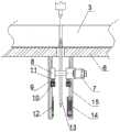
请参阅图1~5,本发明实施例中,一种基于光电控制的晶片切片设备,包括高速锯片切割机构2和激光切割机构1,其中,所述高速锯片切割机构2设置在待切割的晶片3的背面,以便用于从所述晶片的背面切割出切口4,所述激光切割机构1设置在所述待切割的晶片3的正面,以便将已经具有切口4的部位进行彻底切开形成通槽5并切割得到单个晶片;其特征在于,在切片作业时,所述高速锯片切割机构2位于所述激光切割机构1的前方一定距离,以便在切片的切割面处先形成切口4后在一定时间间隔内利用激光切割机构1切割成通槽5;所述高速锯片切割机构2的一侧还设置有对高速锯片的锯切刃进行修整的修整机构;且所述高速锯片切割机构2的一侧还设置有光电检测机构和补偿机构,所述光电检测机构能够对所述高速锯片的锯切刃的直径变化进行检测;Referring to FIGS. 1 to 5 , in an embodiment of the present invention, a photoelectric control-based wafer slicing device includes a high-speed saw
所述补偿机构构设为根据所述光电检测机构检测的值对所述高速锯片切割机构2的位置进行调节与补偿,以便使得所述切口4的深度保持在设定阈值内。The compensation mechanism is configured to adjust and compensate the position of the high-speed saw
在本实施例这,本发明还包括对晶片进行吸附固定的切片工作台6以及设置在所述切片工作台下端面且向下延伸的定位座15,所述高速锯片切割机构2、光电检测机构和补偿机构均设置在所述定位座15上。In this embodiment, the present invention also includes a slicing table 6 for adsorbing and fixing the wafer, and a
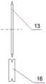
其中,所述高速锯片切割机构2包括锯切轴承座8、驱动电机7和锯切刀片13,其中,所述锯切轴承座8采用所述补偿机构设置在所述定位座上,所述驱动电机7的输出端与所述锯切刀片13的转动主轴驱动连接。The high-speed saw
作为较佳的实施例,所述定位座15为相对间隔且平行设置的两个,两端的所述锯切轴承座8分别设置在所述定位座的竖直补偿滑槽9内,所述补偿机构为精密线性驱动器,所述精密线性驱动器的输出端通过连接柱11连接至所述锯切轴承座8,以便由所述精密线性驱动器调节与补偿所述锯切轴承座8的位置。As a preferred embodiment, the
在本发明中,所述锯切轴承座8的端部与所述滑槽的内壁之间还设置有液压锁紧件17,以便对所述锯切轴承座进行调节补偿之后对所述锯切轴承座进行液压锁紧。In the present invention, a
所述光电检测机构包括激光发射器14和光电接收传感器12,其中,所述激光发射器14固定在所述定位座的底侧,所述光电接收传感器12固定在所述定位座的底侧,且所述激光发射器14与光电接收传感器12正好相对布置,通过所述锯切刀片13的下端部对所述激光发射器14发射的激光的遮挡部位来实现对所述锯切刀片的端刃部直径检测。The photoelectric detection mechanism includes a
所述激光发射器14上阵列设置有多个激光发射头,所述光电接收传感器12上阵列设置有多个光电接收探头,每个所述激光发射头与所述光电接收探头位置相对,且每个光电接收探头的坐标位置已知且一定。所述修整机构包括修整磨轮16、修整驱动盘23和修整电机22,其中,所述修整磨轮与所述修整驱动盘23同轴固定连接,所述修整驱动盘与所述修整电机22传动驱动连接。安装锯切刀片13的所述锯切轴承座8上还固定设置有底架19,所述底架19上铰接设置有转换驱动件20,所述转换驱动件的驱动端铰接连接所述修整机构的修整磨轮处,所述修整机构的下端铰接在所述底架19上,以便由所述转换驱动件20来调节所述修整磨轮的位置,进而实现锯切刀片修整与否的状态转换。The
此外,为了保证高速锯切机构工作的稳定状态,所述底架的底部还固定设置有稳定配重块18。In addition, in order to ensure a stable working state of the high-speed sawing mechanism, a
本发明在切片作业时,高速锯片切割机构位于激光切割机构的前方一定距离,这样,在切片的切割面处先形成切口后在一定时间间隔内利用激光切割机构切割成通槽,可以有效的实现对切片的切割后的部分冷却,而且在冷却完成之前进行切割,防止晶片切割处切割前后温度相差过大而导致变形过大的问题,有效提高晶片的切割精度与稳定性;本发明高速锯片切割机构的一侧还设置有对高速锯片的锯切刃进行修整的修整机构,可有效的提高锯切刀刃的精度与稳定性,提高切割边缘的精度,减少毛刺的产生,并保证各个切片的切割面的一致性,便于后续的研磨规模化加工与处理;本发明的高速锯片切割机构的一侧还置有光电检测机构和补偿机构,光电检测机构对高速锯片的锯切刃的直径变化进行检测,补偿机构根据光电检测机构检测的值对所述高速锯片切割机构的位置进行调节与补偿,使得切口的深度保持在设定阈值内,这样便于与激光切割机进行结合,有效保证各个晶片的切割的稳定性和均匀性。During the slicing operation of the present invention, the high-speed saw blade cutting mechanism is located at a certain distance in front of the laser cutting mechanism. In this way, the incision is first formed at the cutting surface of the slicing, and then the laser cutting mechanism is used to cut the through groove within a certain time interval, which can effectively Realize the cooling of the cutting part of the slice, and cut it before the cooling is completed, to prevent the problem of excessive deformation caused by the excessive temperature difference before and after cutting at the cutting place of the wafer, and effectively improve the cutting precision and stability of the wafer; the high-speed saw of the present invention One side of the blade cutting mechanism is also provided with a trimming mechanism for trimming the sawing edge of the high-speed saw blade, which can effectively improve the accuracy and stability of the sawing blade, improve the accuracy of the cutting edge, reduce the generation of burrs, and ensure that each The consistency of the cutting surfaces of the slices is convenient for subsequent grinding and large-scale processing and processing; the high-speed saw blade cutting mechanism of the present invention is also provided with a photoelectric detection mechanism and a compensation mechanism. The diameter change of the saw blade is detected, and the compensation mechanism adjusts and compensates the position of the high-speed saw blade cutting mechanism according to the value detected by the photoelectric detection mechanism, so that the depth of the incision is kept within the set threshold, which is convenient for combining with the laser cutting machine, Effectively ensure the stability and uniformity of the cutting of each wafer.
以上所述的,仅为本发明较佳的具体实施方式,但本发明的保护范围并不局限于此,任何熟悉本技术领域的技术人员在本发明揭露的技术范围内,根据本发明的技术方案及其发明构思加以等同替换或改变,都应涵盖在本发明的保护范围之内。The above are only preferred specific embodiments of the present invention, but the protection scope of the present invention is not limited thereto. The equivalent replacement or modification of the solution and its inventive concept shall be included within the protection scope of the present invention.
Claims (10)
Translated fromChinesePriority Applications (1)
| Application Number | Priority Date | Filing Date | Title |
|---|---|---|---|
| CN201911051070.9ACN110744731B (en) | 2019-10-30 | 2019-10-30 | A wafer slicing device based on photoelectric control |
Applications Claiming Priority (1)
| Application Number | Priority Date | Filing Date | Title |
|---|---|---|---|
| CN201911051070.9ACN110744731B (en) | 2019-10-30 | 2019-10-30 | A wafer slicing device based on photoelectric control |
Publications (2)
| Publication Number | Publication Date |
|---|---|
| CN110744731Atrue CN110744731A (en) | 2020-02-04 |
| CN110744731B CN110744731B (en) | 2021-07-27 |
Family
ID=69281410
Family Applications (1)
| Application Number | Title | Priority Date | Filing Date |
|---|---|---|---|
| CN201911051070.9AActiveCN110744731B (en) | 2019-10-30 | 2019-10-30 | A wafer slicing device based on photoelectric control |
Country Status (1)
| Country | Link |
|---|---|
| CN (1) | CN110744731B (en) |
Cited By (4)
| Publication number | Priority date | Publication date | Assignee | Title |
|---|---|---|---|---|
| CN112363458A (en)* | 2020-11-04 | 2021-02-12 | 厦门至慧机器人有限公司 | Method for online measuring and compensating diameter of saw blade of sawing machine by using correlation type photoelectric switch or mechanical micro-motion switch |
| CN113053770A (en)* | 2021-03-15 | 2021-06-29 | 上海华力微电子有限公司 | Wafer cutting method |
| CN115366184A (en)* | 2022-10-27 | 2022-11-22 | 济南鼎点数控设备有限公司 | Numerical control carbon fiber pipeline cutting machine and circular cutting compensation method thereof |
| CN115446904A (en)* | 2022-10-27 | 2022-12-09 | 济南鼎点数控设备有限公司 | A CNC carbon fiber pipe cutting machine and ring cutting method thereof |
Citations (25)
| Publication number | Priority date | Publication date | Assignee | Title |
|---|---|---|---|---|
| JPH06151581A (en)* | 1992-11-16 | 1994-05-31 | Hitachi Ltd | Dicing method and device |
| JPH06163687A (en)* | 1992-11-18 | 1994-06-10 | Mitsubishi Electric Corp | Method and device for dicing semiconductor device |
| JP2002370140A (en)* | 2001-06-12 | 2002-12-24 | Disco Abrasive Syst Ltd | Blade monitoring device |
| JP3746422B2 (en)* | 2000-12-05 | 2006-02-15 | シャープ株式会社 | Dicing apparatus and dicing method |
| JP2006116690A (en)* | 2004-09-22 | 2006-05-11 | Disco Abrasive Syst Ltd | Cutting equipment |
| JP2006310396A (en)* | 2005-04-26 | 2006-11-09 | Tokyo Seimitsu Co Ltd | Blade breakage detector |
| CN101165877A (en)* | 2006-10-17 | 2008-04-23 | 株式会社迪思科 | Laser processing method for gallium arsenide wafer |
| US20090244528A1 (en)* | 2008-03-25 | 2009-10-01 | Tokyo Seimitsu Co., Ltd. | Blade breakage and abrasion detecting device |
| CN101927402A (en)* | 2009-06-17 | 2010-12-29 | 三星钻石工业股份有限公司 | Method for cutting off brittle material substrate |
| JP2011110669A (en)* | 2009-11-27 | 2011-06-09 | Disco Abrasive Syst Ltd | Cutting equipment |
| CN102343629A (en)* | 2010-07-26 | 2012-02-08 | 澁谷工业株式会社 | Device and method for cutting fragile material |
| JP2012080029A (en)* | 2010-10-06 | 2012-04-19 | Disco Abrasive Syst Ltd | Cutting device |
| JP2013146800A (en)* | 2012-01-17 | 2013-08-01 | Toyota Motor Corp | Device for adjusting reference position of cutting tool |
| CN104096908A (en)* | 2013-04-03 | 2014-10-15 | 苏州宝时得电动工具有限公司 | Miter saw and cutting depth adjusting method for same |
| CN105312775A (en)* | 2014-06-10 | 2016-02-10 | 三星钻石工业股份有限公司 | Processing method for brittle material substrate |
| JP2016068400A (en)* | 2014-09-30 | 2016-05-09 | 株式会社ディスコ | Division method of ceramic substrate |
| CN105810633A (en)* | 2015-01-16 | 2016-07-27 | 株式会社迪思科 | Method for processing wafer |
| CN106295140A (en)* | 2016-07-29 | 2017-01-04 | 南京海威机械有限公司 | Error compensating method when a kind of numerical control sizing saw machine workpiece is cut sth. askew |
| CN106903810A (en)* | 2015-10-21 | 2017-06-30 | 株式会社迪思科 | cutting device |
| CN108015650A (en)* | 2016-11-02 | 2018-05-11 | 株式会社迪思科 | The processing method of chip |
| CN108943444A (en)* | 2017-05-24 | 2018-12-07 | 株式会社迪思科 | Cutting apparatus |
| CN109311177A (en)* | 2016-04-27 | 2019-02-05 | 法比奥·泼尼股份公司 | There are the roundwood saw and grinding method of abrasive wheel |
| CN109473351A (en)* | 2017-09-08 | 2019-03-15 | 株式会社迪思科 | wafer processing method |
| CN110000940A (en)* | 2018-01-05 | 2019-07-12 | 株式会社迪思科 | Cutting apparatus |
| CN110039674A (en)* | 2018-01-16 | 2019-07-23 | 株式会社迪思科 | The management method and cutting apparatus of cutting tool |
- 2019
- 2019-10-30CNCN201911051070.9Apatent/CN110744731B/enactiveActive
Patent Citations (25)
| Publication number | Priority date | Publication date | Assignee | Title |
|---|---|---|---|---|
| JPH06151581A (en)* | 1992-11-16 | 1994-05-31 | Hitachi Ltd | Dicing method and device |
| JPH06163687A (en)* | 1992-11-18 | 1994-06-10 | Mitsubishi Electric Corp | Method and device for dicing semiconductor device |
| JP3746422B2 (en)* | 2000-12-05 | 2006-02-15 | シャープ株式会社 | Dicing apparatus and dicing method |
| JP2002370140A (en)* | 2001-06-12 | 2002-12-24 | Disco Abrasive Syst Ltd | Blade monitoring device |
| JP2006116690A (en)* | 2004-09-22 | 2006-05-11 | Disco Abrasive Syst Ltd | Cutting equipment |
| JP2006310396A (en)* | 2005-04-26 | 2006-11-09 | Tokyo Seimitsu Co Ltd | Blade breakage detector |
| CN101165877A (en)* | 2006-10-17 | 2008-04-23 | 株式会社迪思科 | Laser processing method for gallium arsenide wafer |
| US20090244528A1 (en)* | 2008-03-25 | 2009-10-01 | Tokyo Seimitsu Co., Ltd. | Blade breakage and abrasion detecting device |
| CN101927402A (en)* | 2009-06-17 | 2010-12-29 | 三星钻石工业股份有限公司 | Method for cutting off brittle material substrate |
| JP2011110669A (en)* | 2009-11-27 | 2011-06-09 | Disco Abrasive Syst Ltd | Cutting equipment |
| CN102343629A (en)* | 2010-07-26 | 2012-02-08 | 澁谷工业株式会社 | Device and method for cutting fragile material |
| JP2012080029A (en)* | 2010-10-06 | 2012-04-19 | Disco Abrasive Syst Ltd | Cutting device |
| JP2013146800A (en)* | 2012-01-17 | 2013-08-01 | Toyota Motor Corp | Device for adjusting reference position of cutting tool |
| CN104096908A (en)* | 2013-04-03 | 2014-10-15 | 苏州宝时得电动工具有限公司 | Miter saw and cutting depth adjusting method for same |
| CN105312775A (en)* | 2014-06-10 | 2016-02-10 | 三星钻石工业股份有限公司 | Processing method for brittle material substrate |
| JP2016068400A (en)* | 2014-09-30 | 2016-05-09 | 株式会社ディスコ | Division method of ceramic substrate |
| CN105810633A (en)* | 2015-01-16 | 2016-07-27 | 株式会社迪思科 | Method for processing wafer |
| CN106903810A (en)* | 2015-10-21 | 2017-06-30 | 株式会社迪思科 | cutting device |
| CN109311177A (en)* | 2016-04-27 | 2019-02-05 | 法比奥·泼尼股份公司 | There are the roundwood saw and grinding method of abrasive wheel |
| CN106295140A (en)* | 2016-07-29 | 2017-01-04 | 南京海威机械有限公司 | Error compensating method when a kind of numerical control sizing saw machine workpiece is cut sth. askew |
| CN108015650A (en)* | 2016-11-02 | 2018-05-11 | 株式会社迪思科 | The processing method of chip |
| CN108943444A (en)* | 2017-05-24 | 2018-12-07 | 株式会社迪思科 | Cutting apparatus |
| CN109473351A (en)* | 2017-09-08 | 2019-03-15 | 株式会社迪思科 | wafer processing method |
| CN110000940A (en)* | 2018-01-05 | 2019-07-12 | 株式会社迪思科 | Cutting apparatus |
| CN110039674A (en)* | 2018-01-16 | 2019-07-23 | 株式会社迪思科 | The management method and cutting apparatus of cutting tool |
Cited By (6)
| Publication number | Priority date | Publication date | Assignee | Title |
|---|---|---|---|---|
| CN112363458A (en)* | 2020-11-04 | 2021-02-12 | 厦门至慧机器人有限公司 | Method for online measuring and compensating diameter of saw blade of sawing machine by using correlation type photoelectric switch or mechanical micro-motion switch |
| CN113053770A (en)* | 2021-03-15 | 2021-06-29 | 上海华力微电子有限公司 | Wafer cutting method |
| CN113053770B (en)* | 2021-03-15 | 2024-03-08 | 上海华力微电子有限公司 | Wafer cutting method |
| CN115366184A (en)* | 2022-10-27 | 2022-11-22 | 济南鼎点数控设备有限公司 | Numerical control carbon fiber pipeline cutting machine and circular cutting compensation method thereof |
| CN115446904A (en)* | 2022-10-27 | 2022-12-09 | 济南鼎点数控设备有限公司 | A CNC carbon fiber pipe cutting machine and ring cutting method thereof |
| CN115446904B (en)* | 2022-10-27 | 2024-09-06 | 济南鼎点数控设备有限公司 | Numerical control carbon fiber pipeline cutting machine and circular cutting method thereof |
Also Published As
| Publication number | Publication date |
|---|---|
| CN110744731B (en) | 2021-07-27 |
Similar Documents
| Publication | Publication Date | Title |
|---|---|---|
| CN110744731A (en) | A wafer slicing device based on photoelectric control | |
| US11273522B2 (en) | Wafer producing method and laser processing apparatus | |
| US9536787B2 (en) | Wafer processing method | |
| CN102490209B (en) | Automatic angle cutting machine | |
| US20160027696A1 (en) | Wafer processing method | |
| CN103377909A (en) | Apparatus and method for the singulation of a semiconductor wafer | |
| JP5554585B2 (en) | Processing method and processing apparatus using a grindstone tool | |
| CN208358057U (en) | A kind of laser cutting machine | |
| CN108436302A (en) | A kind of laser cutting machine | |
| KR101484356B1 (en) | Cutting machine for cylinderical ingot block and method for processing into square columnar block using the same | |
| CN219787009U (en) | Improved semi-automatic wafer dicing cutter | |
| CN209439958U (en) | A kind of scribing machine | |
| CN218135803U (en) | Laser cutting positioning device for heterojunction solar cell | |
| CN216732477U (en) | Semiconductor wafer step type cutting equipment | |
| CN104310778A (en) | Quartz glass slicer | |
| CN101168269A (en) | Hub knives and cutting devices | |
| CN211331496U (en) | A three-side milling combined milling machine for processing slide boxes | |
| CN210524016U (en) | Concave surface machining device | |
| CN210789657U (en) | Laser processing apparatus | |
| JP5511505B2 (en) | Processing method of sapphire wafer | |
| CN201677137U (en) | Laser scribing device for solar silicon crystal plate | |
| CN204504511U (en) | Cutting device | |
| CN221658640U (en) | High-precision milling device | |
| CN222874989U (en) | An automatic wafer splitting machine for chip production | |
| CN220636640U (en) | Miniature laser cutting machine |
Legal Events
| Date | Code | Title | Description |
|---|---|---|---|
| PB01 | Publication | ||
| PB01 | Publication | ||
| SE01 | Entry into force of request for substantive examination | ||
| SE01 | Entry into force of request for substantive examination | ||
| GR01 | Patent grant | ||
| GR01 | Patent grant | ||
| TR01 | Transfer of patent right | ||
| TR01 | Transfer of patent right | Effective date of registration:20240611 Address after:230000 Room 203, building 2, phase I, e-commerce Park, Jinggang Road, Shushan Economic Development Zone, Hefei City, Anhui Province Patentee after:Hefei Jiuzhou Longteng scientific and technological achievement transformation Co.,Ltd. Country or region after:China Address before:Weidu District Bayi Road Xuchang city Henan province 461000 No. 88 Patentee before:XUCHANG University Country or region before:China |