CN110742780A - A kind of outdoor sports training auxiliary exercise equipment and exercise method thereof - Google Patents
A kind of outdoor sports training auxiliary exercise equipment and exercise method thereofDownload PDFInfo
- Publication number
- CN110742780A CN110742780ACN201911115635.5ACN201911115635ACN110742780ACN 110742780 ACN110742780 ACN 110742780ACN 201911115635 ACN201911115635 ACN 201911115635ACN 110742780 ACN110742780 ACN 110742780A
- Authority
- CN
- China
- Prior art keywords
- limiting
- rod
- matched
- seat
- supporting
- Prior art date
- Legal status (The legal status is an assumption and is not a legal conclusion. Google has not performed a legal analysis and makes no representation as to the accuracy of the status listed.)
- Granted
Links
- 238000012549trainingMethods0.000titleclaimsabstractdescription17
- 238000000034methodMethods0.000titleclaimsdescription12
- 230000007246mechanismEffects0.000claimsabstractdescription72
- 238000009434installationMethods0.000claimsdescription11
- 238000003780insertionMethods0.000claimsdescription10
- 230000037431insertionEffects0.000claimsdescription10
- 230000002093peripheral effectEffects0.000claimsdescription9
- 230000009471actionEffects0.000claimsdescription3
- 230000005484gravityEffects0.000claimsdescription3
- 238000005096rolling processMethods0.000claimsdescription3
- 230000003139buffering effectEffects0.000claims1
- 238000010586diagramMethods0.000description7
- 238000013461designMethods0.000description2
- 239000000463materialSubstances0.000description2
- 238000011084recoveryMethods0.000description2
- 241001272996Polyphylla fulloSpecies0.000description1
- 230000009286beneficial effectEffects0.000description1
- 230000006835compressionEffects0.000description1
- 238000007906compressionMethods0.000description1
- 230000000694effectsEffects0.000description1
- 238000012986modificationMethods0.000description1
- 230000004048modificationEffects0.000description1
- 230000000474nursing effectEffects0.000description1
- 230000008569processEffects0.000description1
Images


Classifications
- A—HUMAN NECESSITIES
- A61—MEDICAL OR VETERINARY SCIENCE; HYGIENE
- A61H—PHYSICAL THERAPY APPARATUS, e.g. DEVICES FOR LOCATING OR STIMULATING REFLEX POINTS IN THE BODY; ARTIFICIAL RESPIRATION; MASSAGE; BATHING DEVICES FOR SPECIAL THERAPEUTIC OR HYGIENIC PURPOSES OR SPECIFIC PARTS OF THE BODY
- A61H3/00—Appliances for aiding patients or disabled persons to walk about
- A61H3/04—Wheeled walking aids for patients or disabled persons
- A—HUMAN NECESSITIES
- A61—MEDICAL OR VETERINARY SCIENCE; HYGIENE
- A61H—PHYSICAL THERAPY APPARATUS, e.g. DEVICES FOR LOCATING OR STIMULATING REFLEX POINTS IN THE BODY; ARTIFICIAL RESPIRATION; MASSAGE; BATHING DEVICES FOR SPECIAL THERAPEUTIC OR HYGIENIC PURPOSES OR SPECIFIC PARTS OF THE BODY
- A61H2201/00—Characteristics of apparatus not provided for in the preceding codes
- A61H2201/01—Constructive details
- A61H2201/0192—Specific means for adjusting dimensions
Landscapes
- Health & Medical Sciences (AREA)
- Epidemiology (AREA)
- Pain & Pain Management (AREA)
- Physical Education & Sports Medicine (AREA)
- Rehabilitation Therapy (AREA)
- Life Sciences & Earth Sciences (AREA)
- Animal Behavior & Ethology (AREA)
- General Health & Medical Sciences (AREA)
- Public Health (AREA)
- Veterinary Medicine (AREA)
- Rehabilitation Tools (AREA)
Abstract
Translated fromChineseDescription
Translated fromChinese技术领域technical field
本发明属于运动器械领域,尤其涉及一种室外体育训练辅助运动器械及其运动方法。The invention belongs to the field of sports equipment, in particular to an auxiliary sports equipment for outdoor sports training and an exercise method thereof.
背景技术Background technique
目前在患者的康复护理过程中,经常需要进行户外训练恢复,但是由于考虑到使用者的身体恢复状态不同,经常需要用到辅助器械进行运动,日常会用到助行器进行辅助行走使用,但是传统的助行器结构简单,功能单一,无法根据不同人群的使用需求进行适应性调节,给日常使用带来了不便。At present, in the process of rehabilitation and nursing of patients, outdoor training and recovery are often required. However, considering the different physical recovery states of users, auxiliary equipment is often used for exercise, and walkers are used for assisted walking in daily life, but The traditional walker has a simple structure and a single function, and cannot be adaptively adjusted according to the needs of different groups of people, which brings inconvenience to daily use.
发明内容SUMMARY OF THE INVENTION
本发明的目的在于克服现有技术存在的以上问题,提供一种室外体育训练辅助运动器械及其运动方法。The purpose of the present invention is to overcome the above problems existing in the prior art, and to provide an auxiliary exercise apparatus for outdoor sports training and an exercise method thereof.
为实现上述技术目的,达到上述技术效果,本发明通过以下技术方案实现:In order to realize the above-mentioned technical purpose and achieve the above-mentioned technical effect, the present invention is realized through the following technical solutions:
一种室外体育训练辅助运动器械,包括左右对称分布的两个限位调节机构,两个限位调节机构中间通过支撑板机构相连,限位调节机构顶端连接有限位顶座,限位顶座前侧两端对称安装有手扶支座,限位顶座后侧安装有靠板机构,限位调节机构包括前后对称安装的两个支撑基件,两个支撑基件中间通过承载连接机构相连,两个支撑基件顶端之间通过伸缩调节机构相连,支撑基件顶端通过升降调节机构与限位顶座相连,左右两个支撑基件底端之间通过伸缩限位机构相连,支撑基件底端安装有缓冲支撑机构;The utility model relates to an auxiliary exercise equipment for outdoor sports training, comprising two limit adjustment mechanisms symmetrically distributed on the left and right. The two ends of the side are symmetrically installed with hand-held supports, and the rear side of the limit top seat is installed with a backing plate mechanism. The top ends of the two support bases are connected by a telescopic adjustment mechanism, the top of the support base is connected with the limit top seat through a lift adjustment mechanism, and the bottom ends of the left and right support bases are connected by a telescopic limit mechanism, and the bottom of the support base is connected with the limit top seat. A buffer support mechanism is installed at the end;
所述支撑基件包括支撑底杆以及设置在支撑底杆顶端的支撑斜杆,支撑斜杆顶端竖直设有支撑顶杆,支撑底杆与支撑斜杆交汇处设有第一限位块,支撑斜杆与支撑顶杆交汇处设有第二限位块,支撑顶杆顶端设有升降调节螺孔;The supporting base member includes a supporting bottom rod and a supporting inclined rod arranged at the top end of the supporting bottom rod, the top of the supporting inclined rod is vertically provided with a supporting top rod, and the intersection of the supporting bottom rod and the supporting inclined rod is provided with a first limit block, A second limit block is provided at the intersection of the supporting inclined rod and the supporting top rod, and the top of the supporting top rod is provided with a lifting adjusting screw hole;
所述承载连接机构包括承载中心座以及对称安装在承载中心座两端的承载连接座,承载连接座上方安装有第一内螺纹压套;The bearing connection mechanism comprises a bearing center seat and a bearing connection seat symmetrically installed at both ends of the bearing center seat, and a first inner thread pressing sleeve is installed above the bearing connection seat;
所述伸缩调节机构包括调节中心座以及对称安装在调节中心座两端的伸缩调节座,伸缩调节座上下对称安装有两个第二内螺纹压套;The telescopic adjustment mechanism includes an adjustment center seat and a telescopic adjustment seat symmetrically installed at both ends of the adjustment center seat, and the telescopic adjustment seat is symmetrically installed with two second inner thread pressing sleeves up and down;
所述升降调节机构包括升降调节支座以及安装在升降调节支座顶端的限位卡座;The lift adjustment mechanism includes a lift adjustment support and a limit clip installed on the top of the lift adjustment support;
所述升降调节支座包括与升降调节螺孔相配合的升降调节螺杆,升降调节螺杆顶端设有转动限位块;限位卡座包括滑动安装在升降调节螺杆周侧的外螺纹连接筒,外螺纹连接筒底端设有环形转动凸起;The lifting adjustment support includes a lifting adjustment screw matched with the lifting adjustment screw hole, and the top of the lifting adjustment screw is provided with a rotation limit block; The bottom end of the threaded connection cylinder is provided with an annular rotating protrusion;
所述支撑板机构包括左右分布的第一支撑平板和第二支撑平板,第二支撑平板中间对称安装有两个滑动插件,滑动插件底端通过滑动限位螺栓与第二支撑平板固定连接;The supporting plate mechanism includes a first supporting plate and a second supporting plate distributed left and right, two sliding inserts are symmetrically installed in the middle of the second supporting plate, and the bottom end of the sliding inserts is fixedly connected to the second supporting plate through a sliding limit bolt;
所述伸缩限位机构包括中心连接座以及对称安装在中心连接座两端的伸缩连接梁,中心连接座与伸缩连接梁之间通过限位插件相连;The telescopic limiting mechanism includes a central connecting seat and a telescopic connecting beam symmetrically installed at both ends of the central connecting seat, and the central connecting seat and the telescopic connecting beam are connected by a limit plug-in;
所述限位顶座包括限位前梁以及垂直设置在限位前梁左右两侧的限位侧梁,限位前梁与限位侧梁交汇处底面设有固定连接孔,固定连接孔内顶端设有固定螺孔,固定连接孔周侧均布有转动限位卡槽,限位侧梁底面前端设有与外螺纹连接筒相配合的第一内螺纹连接筒,限位侧梁底面后端设有线性滑槽,线性滑槽中安装有与外螺纹连接筒相配合的第二内螺纹连接筒,第二内螺纹连接筒顶端设有与线性滑槽相配合的滑动卡块;The limit top seat includes a limit front beam and a limit side beam vertically arranged on the left and right sides of the limit front beam. The bottom surface of the intersection of the limit front beam and the limit side beam is provided with a fixed connection hole, and the fixed connection hole is in the bottom surface. There are fixed screw holes at the top, and rotation limit slots are evenly distributed on the circumference of the fixed connection holes. The end is provided with a linear chute, a second inner threaded connection cylinder matched with the external thread connection cylinder is installed in the linear chute, and the top of the second inner threaded connection cylinder is provided with a sliding block matched with the linear chute;
所述手扶支座包括与固定连接孔相配合的固定连接套,固定连接套周侧顶端均布有与转动限位卡槽相配合的转动限位凸起,固定连接套周侧底端垂直设有转动底杆,转动底杆外端竖直设有手扶竖杆,固定连接套中安装有与固定螺孔相配合的固定连接螺栓。The hand support support includes a fixed connection sleeve matched with the fixed connection hole, the top of the peripheral side of the fixed connection sleeve is evenly distributed with rotation limit protrusions matched with the rotation limit slot, and the bottom end of the peripheral side of the fixed connection sleeve is vertical A rotating bottom rod is provided, the outer end of the rotating bottom rod is vertically provided with a hand-held vertical rod, and a fixed connecting bolt matched with the fixed screw hole is installed in the fixed connecting sleeve.
进一步地,所述承载中心座包括承载中心杆以及对称设置在承载中心杆周侧两端的环形限位凸起,承载中心杆两端面对称设有导向连接孔,导向连接孔端口处对称设有两个弹性限位凸起,导向连接孔内端安装有承载连接弹簧;承载连接座包括与导向连接孔相配合的导向连接杆,导向连接杆外端设有与支撑顶杆相配合的第一定位卡套,导向连接杆周侧对称设有两个与弹性限位凸起相配合的滑动限位卡槽;第一定位卡套顶端与第一内螺纹压套紧密接触相连,第一定位卡套底端与第二限位块紧密接触相连。Further, the bearing center seat includes a bearing center rod and annular limit protrusions symmetrically arranged at both ends of the circumferential side of the bearing center rod. The two ends of the bearing center rod are symmetrically provided with guide connecting holes, and two guide connecting holes are symmetrically arranged at the ports of the guide connecting holes. A load-bearing connection spring is installed at the inner end of the guide connection hole; the load-bearing connection seat includes a guide connection rod matched with the guide connection hole, and the outer end of the guide connection rod is provided with a first positioning rod matched with the support ejector rod The ferrule, the peripheral side of the guide connecting rod is symmetrically provided with two sliding limit slots matched with the elastic limit protrusions; the top end of the first positioning ferrule is in close contact with the first inner thread pressing sleeve, and the first positioning ferrule is in close contact with the first positioning ferrule. The bottom end is in close contact with the second limiting block.
进一步地,所述伸缩调节座包括与支撑顶杆相配合的第二定位卡套,第二定位卡套周侧设有内螺纹连接管,第二定位卡套两端面与第二内螺纹压套紧密接触相连;调节中心座包括中心调节块,中心调节块两端分别设有与内螺纹连接管相配合的正螺纹杆和反螺纹杆。Further, the telescopic adjustment seat includes a second positioning ferrule matched with the support rod, the peripheral side of the second positioning ferrule is provided with an inner thread connecting pipe, and the two end surfaces of the second positioning ferrule are connected with the second inner thread pressing sleeve. The adjustment center seat includes a center adjustment block, and the two ends of the center adjustment block are respectively provided with a positive threaded rod and a reverse threaded rod matched with the inner threaded connecting pipe.
进一步地,所述第一支撑平板外端设有与承载中心杆相配合的第一转动连接孔,第一支撑平板内端对称设有两个第一滑动插孔;第二支撑平板外端设有与承载中心杆相配合的第二转动连接孔,第二支撑平板内端对称设有两个第二滑动插孔,第二滑动插孔底端设有滑动限位槽,两个滑动限位槽之间对称设有两个与滑动限位螺栓相配合的滑动限位连接孔;滑动插件包括滑动安装在第二滑动插孔中的滑动插杆,滑动插杆内端底部设有与滑动限位槽相配合的滑动限位块,滑动限位块底端垂直设有定位连接块,定位连接块中间设有用于安装滑动限位螺栓的滑动限位螺孔。Further, the outer end of the first supporting plate is provided with a first rotating connection hole matched with the bearing center rod, the inner end of the first supporting plate is symmetrically provided with two first sliding holes; the outer end of the second supporting plate is provided with two first sliding holes. There is a second rotating connection hole matched with the bearing center rod, the inner end of the second supporting plate is symmetrically provided with two second sliding sockets, the bottom end of the second sliding socket is provided with a sliding limit slot, and the two sliding limit Two sliding limit connection holes matched with the sliding limit bolts are symmetrically arranged between the slots; the sliding plug-in includes a sliding insertion rod slidably installed in the second sliding insertion hole, and the bottom of the inner end of the sliding insertion rod is provided with a sliding limit The sliding limit block matched with the position groove, the bottom end of the sliding limit block is vertically provided with a positioning connecting block, and the middle of the positioning connecting block is provided with a sliding limit screw hole for installing the sliding limit bolt.
进一步地,所述伸缩连接梁一端设有与支撑底杆相配合的连接梁限位孔,伸缩连接梁另一端设有伸缩连接槽,伸缩连接槽端口处设有限位插孔;中心连接座包括中心连接台,中心连接台两端对称设有与伸缩连接槽相配合的伸缩连接条,伸缩连接条表面沿直线方向均布有与限位插孔相对应的限位穿孔;限位插件包括限位端块,限位端块中间对称设有两个弹性卡板,弹性卡板穿过限位插孔连接有卡接凸起。Further, one end of the telescopic connecting beam is provided with a connecting beam limiting hole matched with the supporting bottom rod, the other end of the telescopic connecting beam is provided with a telescopic connecting slot, and a limit jack is provided at the port of the telescopic connecting slot; the central connecting seat includes The central connecting table, the two ends of the central connecting table are symmetrically provided with telescopic connecting strips matched with the telescopic connecting grooves, and the surface of the telescopic connecting strip is evenly distributed with limit perforations corresponding to the limit jacks along the linear direction; the limit plug-ins include limit The limit end block is provided with two elastic clip plates symmetrically in the middle of the limit end block, and the elastic clip plates are connected with the clipping protrusions through the limit jacks.
进一步地,所述缓冲支撑机构包括自上而下依次安装连接的缓冲弹簧、移动支座、固定安装筒;固定安装筒顶端与支撑底杆底端螺纹连接,固定安装筒底端设有支撑限位孔;移动支座包括与支撑限位孔相配合的支撑立柱,支撑立柱顶端设有限位顶块,支撑立柱底端安装有滚动球。Further, the buffer support mechanism includes a buffer spring, a movable support, and a fixed installation cylinder installed and connected in sequence from top to bottom; the top of the fixed installation cylinder is screwed with the bottom end of the supporting bottom rod, and the bottom end of the fixed installation cylinder is provided with a support limiter. The position hole; the moving support includes a support column matched with the support limit hole, a limit block is arranged at the top of the support column, and a rolling ball is installed at the bottom end of the support column.
进一步地,所述靠板机构包括依次安装连接的靠板座、限位弹簧、调节外板、靠板调节件,调节外板一端与限位顶座的一个限位侧梁铰接相连,调节外板另一端与限位顶座的另一个限位侧梁通过卡扣连接,调节外板中间对称设有两个靠板调节螺孔;靠板调节件包括与靠板调节螺孔相配合的靠板调节螺杆,靠板调节螺杆外端设有调节转动块,靠板调节螺杆内端设有压紧连接孔;靠板座包括背靠板,背靠板中间对称设有与压紧连接孔相配合的压紧连接杆,压紧连接杆外侧安装有限位弹簧;限位弹簧两端分别与背靠板、靠板调节螺杆接触相连。Further, the plate-retaining mechanism includes a plate-retaining seat, a limit spring, an adjustment outer plate, and a plate-retaining adjustment member that are installed and connected in sequence, and one end of the adjustment outer plate is hingedly connected to a limit side beam of the limit top seat, and the adjustment outer plate is hingedly connected. The other end of the plate is connected with the other limit side beam of the limit top seat through a buckle, and two backboard adjustment screw holes are symmetrically arranged in the middle of the adjustment outer plate; The plate adjusting screw is provided with an adjusting rotating block at the outer end of the backrest adjusting screw, and a pressing connection hole is arranged at the inner end of the backing adjusting screw; The cooperating pressing connecting rod is installed with a limit spring on the outside of the pressing connecting rod;
本发明还提供一种室外体育训练辅助运动器械的运动方法,所述方法包括以下步骤:The present invention also provides a movement method of an auxiliary sports equipment for outdoor sports training, the method comprising the following steps:
步骤一:首先完成两个限位调节机构的安装:将前后两个支撑基件与承载连接机构配合安装,然后进行伸缩调节机构的组装;Step 1: First complete the installation of the two limit adjustment mechanisms: install the front and rear support bases with the load-bearing connection mechanism, and then assemble the telescopic adjustment mechanism;
步骤二:然后通过伸缩限位机构对左右两个限位调节机构进行配合连接,并将四个缓冲支撑机构安装在支撑基件底端;Step 2: Then, the two left and right limit adjustment mechanisms are matched and connected through the telescopic limit mechanism, and the four buffer support mechanisms are installed on the bottom end of the support base;
步骤三:然后将限位顶座底部的第一内螺纹连接筒和第二内螺纹连接筒分别与前后两个外螺纹连接筒配合安装;Step 3: Then install the first inner threaded connection cylinder and the second inner threaded connection cylinder at the bottom of the limiting top seat with the front and rear outer threaded connection cylinders respectively;
步骤四:分别完成手扶支座和靠板机构的组合安装;Step 4: Complete the combined installation of the hand-held support and the backing mechanism respectively;
步骤五:当使用者需要直立行走时,向下旋转滑动限位螺栓,然后推动滑动插件,使得滑动插杆脱离第一滑动插孔,此时在重力作用下,第一支撑平板和第二支撑平板自由转动至竖直状态,从而便于使用者站立;Step 5: When the user needs to walk upright, rotate the sliding limit bolt downward, and then push the sliding plug-in, so that the sliding plug-in rod is separated from the first sliding socket. At this time, under the action of gravity, the first support plate and the second support The tablet is free to rotate to a vertical state, which is convenient for the user to stand;
当需要进行高度调节时,旋转升降调节螺杆即可;When height adjustment is required, just rotate the lift adjustment screw;
当需要进行手扶竖杆的位置调节时,向下旋转固定连接螺栓,然后拔出旋转手扶支座并进行旋转调节即可;When it is necessary to adjust the position of the hand-held vertical rod, rotate the fixed connecting bolt downwards, then pull out the rotating hand-held support and perform rotational adjustment;
当需要对背靠板的前后位置进行调节时,只需要旋转靠板调节件即可。When the front and rear positions of the backrest plate need to be adjusted, it is only necessary to rotate the backrest plate adjusting member.
本发明的有益效果是:The beneficial effects of the present invention are:
本发明通过科学合理的结构设计,能够根据使用者的需求进行高度、和相关尺寸调节,同时能够实时进行行走状态和坐立状态的结构形态切换,通过缓冲支撑机构的缓冲支撑,能够在使用过程中对使用者进行良好的支撑保护,适用于不同地形的使用需求,结构调节方便,具有良好的实用与推广价值。Through scientific and reasonable structural design, the present invention can adjust the height and related dimensions according to the needs of users, and can switch between the walking state and the sitting state in real time. It has good support and protection for users, is suitable for the use needs of different terrains, and has convenient structural adjustment, which has good practical and popularization value.
附图说明Description of drawings
此处所说明的附图用来提供对本发明的进一步理解,构成本申请的一部分,本发明的示意性实施例及其说明用于解释本发明,并不构成对本发明的不当限定。在附图中:The accompanying drawings described herein are used to provide a further understanding of the present invention and constitute a part of the present application. The exemplary embodiments of the present invention and their descriptions are used to explain the present invention and do not constitute an improper limitation of the present invention. In the attached image:
图1是本发明的结构示意图;Fig. 1 is the structural representation of the present invention;
图2是本发明的局部结构示意图;Fig. 2 is the partial structure schematic diagram of the present invention;
图3是本发明的局部结构示意图;Fig. 3 is the partial structure schematic diagram of the present invention;
图4是本发明的局部结构爆炸图;Fig. 4 is the partial structure exploded view of the present invention;
图5是本发明的局部结构示意图;Fig. 5 is the partial structure schematic diagram of the present invention;
图6是本发明的局部结构爆炸图;Fig. 6 is the partial structure exploded diagram of the present invention;
图7是本发明的局部结构示意图;Fig. 7 is the partial structure schematic diagram of the present invention;
图8是本发明的局部结构爆炸图;Fig. 8 is the partial structure exploded view of the present invention;
图9是本发明的局部结构示意图;Fig. 9 is the partial structure schematic diagram of the present invention;
图10是本发明的局部结构爆炸图;Figure 10 is a partial structure exploded view of the present invention;
图11是本发明的局部结构爆炸图;Figure 11 is a partial structure exploded view of the present invention;
图12是本发明的局部结构示意图;Fig. 12 is the partial structure schematic diagram of the present invention;
图13是本发明的局部结构爆炸图;Figure 13 is a partial structure exploded view of the present invention;
图14是本发明的局部结构爆炸图;Figure 14 is a partial structure exploded view of the present invention;
图15是本发明的局部结构爆炸图;Figure 15 is a partial structure exploded view of the present invention;
图16是本发明的局部结构爆炸图;Figure 16 is a partial structure exploded view of the present invention;
图17是本发明的局部结构爆炸图。Fig. 17 is an exploded view of a partial structure of the present invention.
具体实施方式Detailed ways
下面将结合本发明实施例中的附图,对本发明实施例中的技术方案进行清楚、完整地描述,显然,所描述的实施例仅仅是本发明一部分实施例,而不是全部的实施例。基于本发明中的实施例,本领域普通技术人员在没有作出创造性劳动前提下所获得的所有其它实施例,都属于本发明保护的范围。The technical solutions in the embodiments of the present invention will be clearly and completely described below with reference to the accompanying drawings in the embodiments of the present invention. Obviously, the described embodiments are only a part of the embodiments of the present invention, but not all of the embodiments. Based on the embodiments of the present invention, all other embodiments obtained by those of ordinary skill in the art without creative efforts shall fall within the protection scope of the present invention.
在本发明的描述中,需要理解的是,术语“开孔”、“上”、“下”、“厚度”、“顶”、“中”、“长度”、“内”、“四周”等指示方位或位置关系,仅是为了便于描述本发明和简化描述,而不是指示或暗示所指的组件或元件必须具有特定的方位,以特定的方位构造和操作,因此不能理解为对本发明的限制。In the description of the present invention, it is to be understood that the terms "opening", "upper", "lower", "thickness", "top", "middle", "length", "inside", "around", etc. Indicates the orientation or positional relationship, only for the convenience of describing the present invention and simplifying the description, rather than indicating or implying that the components or elements referred to must have a specific orientation, are constructed and operated in a specific orientation, and therefore should not be construed as a limitation of the present invention .
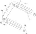
如图1所示的一种室外体育训练辅助运动器械,包括左右对称分布的两个限位调节机构10,两个限位调节机构10中间通过支撑板机构20相连,限位调节机构10顶端连接有限位顶座1,限位顶座1前侧两端对称安装有手扶支座2,限位顶座1后侧安装有靠板机构3,限位调节机构10包括前后对称安装的两个支撑基件4,两个支撑基件4中间通过承载连接机构5相连,两个支撑基件4顶端之间通过伸缩调节机构6相连,支撑基件4顶端通过升降调节机构7与限位顶座1相连,左右两个支撑基件4底端之间通过伸缩限位机构8相连,支撑基件4底端安装有缓冲支撑机构9;As shown in FIG. 1, an auxiliary exercise equipment for outdoor sports training includes two
如图2所示,支撑基件4包括支撑底杆41以及设置在支撑底杆41顶端的支撑斜杆42,支撑斜杆42顶端竖直设有支撑顶杆43,支撑底杆41与支撑斜杆42交汇处设有第一限位块44,支撑斜杆42与支撑顶杆43交汇处设有第二限位块45,支撑顶杆43顶端设有升降调节螺孔46;As shown in FIG. 2 , the
如图3所示,承载连接机构5包括承载中心座51以及对称安装在承载中心座51两端的承载连接座52,承载连接座52上方安装有第一内螺纹压套53;As shown in FIG. 3 , the bearing connecting
如图4所示,承载中心座51包括承载中心杆511以及对称设置在承载中心杆511周侧两端的环形限位凸起512,承载中心杆511两端面对称设有导向连接孔513,导向连接孔513端口处对称设有两个弹性限位凸起514,导向连接孔513内端安装有承载连接弹簧54;承载连接座52包括与导向连接孔513相配合的导向连接杆521,导向连接杆521外端设有与支撑顶杆43相配合的第一定位卡套522,导向连接杆521周侧对称设有两个与弹性限位凸起514相配合的滑动限位卡槽523;第一定位卡套522顶端与第一内螺纹压套53紧密接触相连,第一定位卡套522底端与第二限位块45紧密接触相连;As shown in FIG. 4 , the bearing center seat 51 includes a
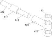
如图5所示,伸缩调节机构6包括调节中心座61以及对称安装在调节中心座61两端的伸缩调节座62,伸缩调节座62上下对称安装有两个第二内螺纹压套63;As shown in FIG. 5 , the
如图6所示,伸缩调节座62包括与支撑顶杆43相配合的第二定位卡套621,第二定位卡套621周侧设有内螺纹连接管622,第二定位卡套621两端面与第二内螺纹压套63紧密接触相连;调节中心座61包括中心调节块611,中心调节块611两端分别设有与内螺纹连接管622相配合的正螺纹杆612和反螺纹杆613;As shown in FIG. 6 , the
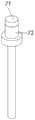
如图7所示,升降调节机构7包括升降调节支座71以及安装在升降调节支座71顶端的限位卡座72;As shown in FIG. 7 , the
如图8所示,升降调节支座71包括与升降调节螺孔46相配合的升降调节螺杆711,升降调节螺杆711顶端设有转动限位块712;限位卡座72包括滑动安装在升降调节螺杆711周侧的外螺纹连接筒721,外螺纹连接筒721底端设有环形转动凸起722;As shown in FIG. 8 , the
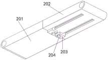
如图9所示,支撑板机构20包括左右分布的第一支撑平板201和第二支撑平板202,第二支撑平板202中间对称安装有两个滑动插件203,滑动插件203底端通过滑动限位螺栓204与第二支撑平板202固定连接;As shown in FIG. 9 , the supporting
如图10和图11所示,第一支撑平板201外端设有与承载中心杆511相配合的第一转动连接孔2011,第一支撑平板201内端对称设有两个第一滑动插孔2012;第二支撑平板202外端设有与承载中心杆511相配合的第二转动连接孔2021,第二支撑平板202内端对称设有两个第二滑动插孔2022,第二滑动插孔2022底端设有滑动限位槽2023,两个滑动限位槽2023之间对称设有两个与滑动限位螺栓204相配合的滑动限位连接孔2024;滑动插件203包括滑动安装在第二滑动插孔2022中的滑动插杆2031,滑动插杆2031内端底部设有与滑动限位槽2023相配合的滑动限位块2032,滑动限位块2032底端垂直设有定位连接块2033,定位连接块2033中间设有用于安装滑动限位螺栓204的滑动限位螺孔2034;As shown in FIG. 10 and FIG. 11 , the outer end of the first supporting
如图12所示,伸缩限位机构8包括中心连接座81以及对称安装在中心连接座81两端的伸缩连接梁82,中心连接座81与伸缩连接梁82之间通过限位插件83相连;As shown in FIG. 12 , the telescopic limiting
如图13所示,伸缩连接梁82一端设有与支撑底杆41相配合的连接梁限位孔821,伸缩连接梁82另一端设有伸缩连接槽822,伸缩连接槽822端口处设有限位插孔823;中心连接座81包括中心连接台811,中心连接台811两端对称设有与伸缩连接槽822相配合的伸缩连接条812,伸缩连接条812表面沿直线方向均布有与限位插孔823相对应的限位穿孔813;限位插件83包括限位端块831,限位端块831中间对称设有两个弹性卡板832,弹性卡板832穿过限位插孔823连接有卡接凸起833;As shown in FIG. 13 , one end of the telescopic connecting
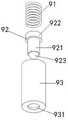
如图14所示,缓冲支撑机构9包括自上而下依次安装连接的缓冲弹簧91、移动支座92、固定安装筒93;固定安装筒93顶端与支撑底杆41底端螺纹连接,固定安装筒93底端设有支撑限位孔931;移动支座92包括与支撑限位孔931相配合的支撑立柱921,支撑立柱921顶端设有限位顶块922,支撑立柱921底端安装有滚动球923;As shown in FIG. 14 , the buffer support mechanism 9 includes a
如图15所示,限位顶座1包括限位前梁11以及垂直设置在限位前梁11左右两侧的限位侧梁12,限位前梁11与限位侧梁12交汇处底面设有固定连接孔13,固定连接孔13内顶端设有固定螺孔14,固定连接孔13周侧均布有转动限位卡槽15,限位侧梁12底面前端设有与外螺纹连接筒721相配合的第一内螺纹连接筒16,限位侧梁12底面后端设有线性滑槽17,线性滑槽17中安装有与外螺纹连接筒721相配合的第二内螺纹连接筒18,第二内螺纹连接筒18顶端设有与线性滑槽17相配合的滑动卡块19;As shown in FIG. 15 , the limit
如图16所示,手扶支座2包括与固定连接孔13相配合的固定连接套21,固定连接套21周侧顶端均布有与转动限位卡槽15相配合的转动限位凸起24,固定连接套21周侧底端垂直设有转动底杆22,转动底杆22外端竖直设有手扶竖杆23,固定连接套21中安装有与固定螺孔14相配合的固定连接螺栓25;As shown in FIG. 16 , the
如图17所示,靠板机构3包括依次安装连接的靠板座31、限位弹簧32、调节外板33、靠板调节件34,调节外板33一端与限位顶座1的一个限位侧梁12铰接相连,调节外板33另一端与限位顶座1的另一个限位侧梁12通过卡扣连接,调节外板33中间对称设有两个靠板调节螺孔331;靠板调节件34包括与靠板调节螺孔331相配合的靠板调节螺杆341,靠板调节螺杆341外端设有调节转动块342,靠板调节螺杆341内端设有压紧连接孔343;靠板座31包括背靠板311,背靠板311中间对称设有与压紧连接孔343相配合的压紧连接杆312,压紧连接杆312外侧安装有限位弹簧32;限位弹簧32两端分别与背靠板311、靠板调节螺杆341接触相连。As shown in FIG. 17 , the
本发明还提供一种室外体育训练辅助运动器械的运动方法,方法包括以下步骤:The present invention also provides an exercise method for an auxiliary exercise device for outdoor sports training, the method comprising the following steps:
步骤一:首先完成两个限位调节机构10的安装:将前后两个支撑基件4与承载连接机构5配合安装,然后进行伸缩调节机构6的组装;Step 1: First complete the installation of the two limit adjustment mechanisms 10 : the front and
步骤二:然后通过伸缩限位机构8对左右两个限位调节机构10进行配合连接,并将四个缓冲支撑机构9安装在支撑基件4底端;Step 2: Then, the two left and right
步骤三:然后将限位顶座1底部的第一内螺纹连接筒16和第二内螺纹连接筒18分别与前后两个外螺纹连接筒721配合安装;Step 3: Then install the first inner threaded
步骤四:分别完成手扶支座2和靠板机构3的组合安装;Step 4: Complete the combined installation of the hand-held
步骤五:当使用者需要直立行走时,向下旋转滑动限位螺栓204,然后推动滑动插件203,使得滑动插杆2031脱离第一滑动插孔2012,此时在重力作用下,第一支撑平板201和第二支撑平板202自由转动至竖直状态,从而便于使用者站立;Step 5: When the user needs to walk upright, rotate the sliding
当需要进行高度调节时,旋转升降调节螺杆711即可;When the height adjustment is required, just rotate the
当需要进行手扶竖杆23的位置调节时,向下旋转固定连接螺栓25,然后拔出旋转手扶支座2并进行旋转调节即可;When it is necessary to adjust the position of the hand-held
当需要对背靠板311的前后位置进行调节时,只需要旋转靠板调节件34即可。When the front and rear positions of the
本发明通过科学合理的结构设计,能够根据使用者的需求进行高度、和相关尺寸调节,同时能够实时进行行走状态和坐立状态的结构形态切换,通过缓冲支撑机构的缓冲支撑,能够在使用过程中对使用者进行良好的支撑保护,适用于不同地形的使用需求,结构调节方便,具有良好的实用与推广价值。Through scientific and reasonable structural design, the present invention can adjust the height and related dimensions according to the needs of users, and can switch between the walking state and the sitting state in real time. It has good support and protection for users, is suitable for the use needs of different terrains, and has convenient structural adjustment, which has good practical and popularization value.
在本说明书的描述中,参考术语“一个实施例”、“示例”、“具体示例”等的描述意指结合该实施例或示例描述的具体特征、结构、材料或者特点包含于本发明的至少一个实施例或示例中。在本说明书中,对上述术语的示意性表述不一定指的是相同的实施例或示例。而且,描述的具体特征、结构、材料或者特点可以在任何的一个或多个实施例或示例中以合适的方式结合。In the description of this specification, description with reference to the terms "one embodiment," "example," "specific example," etc. means that a particular feature, structure, material, or characteristic described in connection with the embodiment or example is included in at least one aspect of the present invention. in one embodiment or example. In this specification, schematic representations of the above terms do not necessarily refer to the same embodiment or example. Furthermore, the particular features, structures, materials or characteristics described may be combined in any suitable manner in any one or more embodiments or examples.
以上显示和描述了本发明的基本原理、主要特征和本发明的优点。本行业的技术人员应该了解,本发明不受上述实施例的限制,上述实施例和说明书中描述的只是说明本发明的原理,在不脱离本发明精神和范围的前提下,本发明还会有各种变化和改进,这些变化和改进都落入要求保护的本发明范围内。The foregoing has shown and described the basic principles, main features and advantages of the present invention. Those skilled in the art should understand that the present invention is not limited by the above-mentioned embodiments, and the descriptions in the above-mentioned embodiments and the description are only to illustrate the principle of the present invention. Without departing from the spirit and scope of the present invention, the present invention will have Various changes and modifications fall within the scope of the claimed invention.
Claims (8)
Priority Applications (1)
| Application Number | Priority Date | Filing Date | Title |
|---|---|---|---|
| CN201911115635.5ACN110742780B (en) | 2019-11-14 | 2019-11-14 | Outdoor physical training auxiliary sports apparatus and sports method thereof |
Applications Claiming Priority (1)
| Application Number | Priority Date | Filing Date | Title |
|---|---|---|---|
| CN201911115635.5ACN110742780B (en) | 2019-11-14 | 2019-11-14 | Outdoor physical training auxiliary sports apparatus and sports method thereof |
Publications (2)
| Publication Number | Publication Date |
|---|---|
| CN110742780Atrue CN110742780A (en) | 2020-02-04 |
| CN110742780B CN110742780B (en) | 2021-09-17 |
Family
ID=69283329
Family Applications (1)
| Application Number | Title | Priority Date | Filing Date |
|---|---|---|---|
| CN201911115635.5AActiveCN110742780B (en) | 2019-11-14 | 2019-11-14 | Outdoor physical training auxiliary sports apparatus and sports method thereof |
Country Status (1)
| Country | Link |
|---|---|
| CN (1) | CN110742780B (en) |
Cited By (2)
| Publication number | Priority date | Publication date | Assignee | Title |
|---|---|---|---|---|
| CN111362000A (en)* | 2020-03-09 | 2020-07-03 | 彩虹(合肥)液晶玻璃有限公司 | Glass substrate carrying and installing mechanism |
| CN111419646A (en)* | 2020-04-02 | 2020-07-17 | 武汉尚诚源健康科技有限公司 | Folding walking aid of accomodating |
Citations (10)
| Publication number | Priority date | Publication date | Assignee | Title |
|---|---|---|---|---|
| DE3683045D1 (en)* | 1985-02-19 | 1992-01-30 | Parir Trading I Avesta Ab | HELPER. |
| CN1250636A (en)* | 1998-10-01 | 2000-04-19 | 多芬发展与投资有限公司 | Seat piece used on chair with adjustable depth |
| CN201205345Y (en)* | 2008-05-27 | 2009-03-11 | 李晓彬 | Hemiplegy rehabilitation travelling aid wheel |
| CN103110488A (en)* | 2013-03-12 | 2013-05-22 | 纪普 | Walk-aid recovery wheel chair with folding telescopic servo seat face |
| CN204910022U (en)* | 2015-08-31 | 2015-12-30 | 朱秋红 | Bone fracture patient is strong with helping capable ware again |
| CN208017737U (en)* | 2017-09-11 | 2018-10-30 | 南陵县生产力促进中心有限公司 | A kind of multifunctional medical auxiliary instrument |
| CN208048978U (en)* | 2017-11-08 | 2018-11-06 | 新乡医学院第三附属医院 | A kind of walking rehabilitation equipment |
| CN109846619A (en)* | 2019-03-04 | 2019-06-07 | 漯河市第一人民医院 | A kind of nursing device for rehabilitation of orthopedic patients |
| CN209033090U (en)* | 2018-06-13 | 2019-06-28 | 遵义医学院附属医院 | A multifunctional walker for critically ill patients |
| CN209611671U (en)* | 2019-01-30 | 2019-11-12 | 汪泳 | A kind of loss of weight rehabilitation running gear |
- 2019
- 2019-11-14CNCN201911115635.5Apatent/CN110742780B/enactiveActive
Patent Citations (10)
| Publication number | Priority date | Publication date | Assignee | Title |
|---|---|---|---|---|
| DE3683045D1 (en)* | 1985-02-19 | 1992-01-30 | Parir Trading I Avesta Ab | HELPER. |
| CN1250636A (en)* | 1998-10-01 | 2000-04-19 | 多芬发展与投资有限公司 | Seat piece used on chair with adjustable depth |
| CN201205345Y (en)* | 2008-05-27 | 2009-03-11 | 李晓彬 | Hemiplegy rehabilitation travelling aid wheel |
| CN103110488A (en)* | 2013-03-12 | 2013-05-22 | 纪普 | Walk-aid recovery wheel chair with folding telescopic servo seat face |
| CN204910022U (en)* | 2015-08-31 | 2015-12-30 | 朱秋红 | Bone fracture patient is strong with helping capable ware again |
| CN208017737U (en)* | 2017-09-11 | 2018-10-30 | 南陵县生产力促进中心有限公司 | A kind of multifunctional medical auxiliary instrument |
| CN208048978U (en)* | 2017-11-08 | 2018-11-06 | 新乡医学院第三附属医院 | A kind of walking rehabilitation equipment |
| CN209033090U (en)* | 2018-06-13 | 2019-06-28 | 遵义医学院附属医院 | A multifunctional walker for critically ill patients |
| CN209611671U (en)* | 2019-01-30 | 2019-11-12 | 汪泳 | A kind of loss of weight rehabilitation running gear |
| CN109846619A (en)* | 2019-03-04 | 2019-06-07 | 漯河市第一人民医院 | A kind of nursing device for rehabilitation of orthopedic patients |
Cited By (3)
| Publication number | Priority date | Publication date | Assignee | Title |
|---|---|---|---|---|
| CN111362000A (en)* | 2020-03-09 | 2020-07-03 | 彩虹(合肥)液晶玻璃有限公司 | Glass substrate carrying and installing mechanism |
| CN111362000B (en)* | 2020-03-09 | 2021-08-31 | 彩虹(合肥)液晶玻璃有限公司 | Glass substrate carrying and installing mechanism |
| CN111419646A (en)* | 2020-04-02 | 2020-07-17 | 武汉尚诚源健康科技有限公司 | Folding walking aid of accomodating |
Also Published As
| Publication number | Publication date |
|---|---|
| CN110742780B (en) | 2021-09-17 |
Similar Documents
| Publication | Publication Date | Title |
|---|---|---|
| CN210963771U (en) | Department of neurology rehabilitation training device | |
| CN110742780A (en) | A kind of outdoor sports training auxiliary exercise equipment and exercise method thereof | |
| CN110812779B (en) | A kind of adjustable indoor physical fitness training equipment and training method thereof | |
| CN108542167A (en) | A kind of multifunction seat | |
| CN110478857A (en) | A kind of comprehensive training device of sports with rotation and drawing mechanism | |
| TWM541790U (en) | Adjustment structure of pedaling rotation function of chair | |
| CN205923552U (en) | Chair with pedal rotation function | |
| CN207871400U (en) | A kind of sporting devices for leg exercises | |
| CN222765383U (en) | Detachable foot pedal of wheelchair | |
| CN212308801U (en) | Sports apparatus hand rehabilitation training device | |
| CN207800121U (en) | A kind of music bracket | |
| CN208018037U (en) | A kind of callisthenics force exerciser | |
| CN2151777Y (en) | Compression torsion exerciser | |
| CN205849737U (en) | A kind of old people's air defense is fallen walking aid | |
| CN214679887U (en) | A kind of rehabilitation training equipment for psychiatry | |
| CN110853602A (en) | Multifunctional Chinese zither support frame and using method thereof | |
| CN216240386U (en) | Safety ladder for building engineering | |
| CN217089938U (en) | Portable easel | |
| CN213553471U (en) | Sitting-up type moving device for assisting old people | |
| CN111282204A (en) | Portable leg training device | |
| CN219646185U (en) | Walking aid rack | |
| CN210728174U (en) | Cardiovascular patient rehabilitation auxiliary walking chair | |
| CN219333108U (en) | Multifunctional dance barre | |
| CN216568896U (en) | A multi-faceted angle-adjustable desk | |
| CN215081741U (en) | A walker with its own networking function for easy fixation |
Legal Events
| Date | Code | Title | Description |
|---|---|---|---|
| PB01 | Publication | ||
| PB01 | Publication | ||
| SE01 | Entry into force of request for substantive examination | ||
| SE01 | Entry into force of request for substantive examination | ||
| GR01 | Patent grant | ||
| GR01 | Patent grant |