CN110736484B - Calibration method of background magnetic field based on fusion of gyroscope and magnetic sensor - Google Patents
Calibration method of background magnetic field based on fusion of gyroscope and magnetic sensorDownload PDFInfo
- Publication number
- CN110736484B CN110736484BCN201911127010.0ACN201911127010ACN110736484BCN 110736484 BCN110736484 BCN 110736484BCN 201911127010 ACN201911127010 ACN 201911127010ACN 110736484 BCN110736484 BCN 110736484B
- Authority
- CN
- China
- Prior art keywords
- magnetic field
- gyroscope
- magnetic sensor
- coordinate system
- follows
- Prior art date
- Legal status (The legal status is an assumption and is not a legal conclusion. Google has not performed a legal analysis and makes no representation as to the accuracy of the status listed.)
- Active
Links
- 238000000034methodMethods0.000titleclaimsabstractdescription24
- 230000004927fusionEffects0.000titleclaimsabstractdescription17
- 238000005259measurementMethods0.000claimsabstractdescription42
- 238000004364calculation methodMethods0.000claimsdescription36
- 230000005358geomagnetic fieldEffects0.000claimsdescription27
- 239000011159matrix materialSubstances0.000claimsdescription20
- 230000005415magnetizationEffects0.000claimsdescription11
- 238000009434installationMethods0.000claimsdescription9
- 230000008859changeEffects0.000claimsdescription7
- 230000006698inductionEffects0.000claims2
- 238000004422calculation algorithmMethods0.000abstractdescription10
- 238000005516engineering processMethods0.000abstractdescription5
- NAWXUBYGYWOOIX-SFHVURJKSA-N(2s)-2-[[4-[2-(2,4-diaminoquinazolin-6-yl)ethyl]benzoyl]amino]-4-methylidenepentanedioic acidChemical compoundC1=CC2=NC(N)=NC(N)=C2C=C1CCC1=CC=C(C(=O)N[C@@H](CC(=C)C(O)=O)C(O)=O)C=C1NAWXUBYGYWOOIX-SFHVURJKSA-N0.000description3
- 238000001514detection methodMethods0.000description3
- 230000002452interceptive effectEffects0.000description3
- 238000010586diagramMethods0.000description2
- 238000012986modificationMethods0.000description2
- 230000004048modificationEffects0.000description2
- 238000012546transferMethods0.000description2
- 230000009471actionEffects0.000description1
- 238000013528artificial neural networkMethods0.000description1
- 230000009286beneficial effectEffects0.000description1
- 230000007547defectEffects0.000description1
- 238000005265energy consumptionMethods0.000description1
- 238000004377microelectronicMethods0.000description1
- 230000008569processEffects0.000description1
- 230000005855radiationEffects0.000description1
- 238000011160researchMethods0.000description1
- 238000012360testing methodMethods0.000description1
Images


Classifications
- G—PHYSICS
- G01—MEASURING; TESTING
- G01C—MEASURING DISTANCES, LEVELS OR BEARINGS; SURVEYING; NAVIGATION; GYROSCOPIC INSTRUMENTS; PHOTOGRAMMETRY OR VIDEOGRAMMETRY
- G01C25/00—Manufacturing, calibrating, cleaning, or repairing instruments or devices referred to in the other groups of this subclass
Landscapes
- Engineering & Computer Science (AREA)
- Manufacturing & Machinery (AREA)
- Physics & Mathematics (AREA)
- General Physics & Mathematics (AREA)
- Radar, Positioning & Navigation (AREA)
- Remote Sensing (AREA)
- Measuring Magnetic Variables (AREA)
Abstract
Translated fromChinese
Description
Translated fromChinese技术领域technical field
本发明涉及磁场检测的技术领域,尤其涉及一种基于陀螺仪及磁传感器融合的背景磁场标定方法。The invention relates to the technical field of magnetic field detection, in particular to a background magnetic field calibration method based on the fusion of a gyroscope and a magnetic sensor.
背景技术Background technique
地磁场是地球连续分布的稳定物理场,是一种非常理想的参考基准。随着微电子技术在地磁探测传感器方面的应用,使得地磁探测技术获得了巨大的进步,由于地磁场导航定位,具有无源、无辐射、抗干扰、全天时、全天候、体积小、能耗低的优点,因此在飞机、导弹制导、舰船和潜艇等领域得到广泛的关注和研究应用。根据Tolles-Lawson理论,任何在空间中运动的物体都会产生背景磁场。导航载体通过捷联式磁传感器测得的磁场信息包括导航定位所用的目标磁场信息和其他干扰磁场信息,这些干扰磁场统称为背景磁场,因此,为了获得准确的导航定位信息,对这些背景磁场误差的标定显得至关重要。本专利主要考虑的背景磁场为固定磁场(又称为剩余磁场)、感应磁场。The geomagnetic field is a continuously distributed and stable physical field of the earth, and it is a very ideal reference. With the application of microelectronics technology in geomagnetic detection sensors, geomagnetic detection technology has made great progress. Due to the geomagnetic field navigation and positioning, it has passive, non-radiation, anti-interference, all-weather, all-weather, small size, energy consumption Therefore, it has received extensive attention and research applications in the fields of aircraft, missile guidance, ships and submarines. According to the Tolles-Lawson theory, any object moving in space produces a background magnetic field. The magnetic field information measured by the navigation carrier through the strapdown magnetic sensor includes the target magnetic field information used for navigation and positioning and other interfering magnetic field information. These interfering magnetic fields are collectively referred to as the background magnetic field. calibration appears to be crucial. The background magnetic fields mainly considered in this patent are fixed magnetic fields (also known as residual magnetic fields) and induced magnetic fields.
在没有背景磁场作用下,理想磁场轨迹为一个原点在圆心,半径为当地地磁矢量模值的的圆球面。在背景磁场作用下由地磁矢量构成的圆球面的原点位置和球体形状都发生变化,理想磁场轨迹变成了圆心不在原点的一个椭球。目前对背景磁场误差的标定就是寻找一组最优的椭球参数,使得磁传感器测量的磁场矢量与拟合的椭球之间距离最小。In the absence of the background magnetic field, the ideal magnetic field trajectory is a spherical surface with the origin at the center and the radius of the local geomagnetic vector modulus. Under the action of the background magnetic field, the origin position and shape of the sphere formed by the geomagnetic vector change, and the ideal magnetic field trajectory becomes an ellipsoid whose center is not at the origin. The current calibration of the background magnetic field error is to find a set of optimal ellipsoid parameters to minimize the distance between the magnetic field vector measured by the magnetic sensor and the fitted ellipsoid.
目前对于背景磁场标定的方法大多数都是基于磁传感器的测量信息进行椭球拟合。但是磁传感器的测量误差精度较低,在实际工程应用中会对背景磁场标定精度造成一定的影响。Most of the current methods for calibrating the background magnetic field are based on the measurement information of the magnetic sensor for ellipsoid fitting. However, the measurement error accuracy of the magnetic sensor is low, which will have a certain impact on the calibration accuracy of the background magnetic field in practical engineering applications.
发明内容SUMMARY OF THE INVENTION
为解决现有技术存在的局限和缺陷,本发明提供一种基于陀螺仪及磁传感器融合的背景磁场标定方法,包括:In order to solve the limitations and defects existing in the prior art, the present invention provides a background magnetic field calibration method based on the fusion of a gyroscope and a magnetic sensor, including:
将磁传感器安装在弹体之内,所述磁传感器的安装点位于所述弹体的质心,以使所述磁传感器的三个轴分别与陀螺仪坐标系的三个坐标轴、弹体坐标系的三个坐标轴平行而且方向一致;The magnetic sensor is installed in the projectile body, and the installation point of the magnetic sensor is located at the center of mass of the projectile body, so that the three axes of the magnetic sensor are respectively connected with the three coordinate axes of the gyroscope coordinate system and the coordinates of the projectile body. The three coordinate axes of the system are parallel and in the same direction;
使用陀螺仪测量载体的姿态角γ,θ,ψ;Use the gyroscope to measure the attitude angles γ, θ, ψ of the carrier;
根据所述陀螺仪初始状态的姿态角γ0,θ0,ψ0,以及所述陀螺仪测量的姿态角γ,θ,ψ,计算载体坐标系Hb,当地磁场强度为He=[HN,HE,HZ]T,陀螺仪测量的磁场强度HM=Hb;According to the attitude angles γ0 , θ0 , ψ0 of the initial state of the gyroscope, and the attitude angles γ, θ, ψ measured by the gyroscope, the carrier coordinate system Hb is calculated, and the local magnetic field strength isHe = [HN ,HE , HZ ]T , the magnetic field strength HM = Hb measured by the gyroscope;
获得磁传感器测量的磁场强度为:The magnetic field strength measured by the magnetic sensor is obtained as:

其中,


设置判定函数Ω(t),所述判定函数Ω(t)与陀螺仪精度、磁传感器精度、陀螺仪的测量误差、磁传感器的测量误差相关;A determination function Ω(t) is set, and the determination function Ω(t) is related to the accuracy of the gyroscope, the accuracy of the magnetic sensor, the measurement error of the gyroscope, and the measurement error of the magnetic sensor;
当t<Ω(t)时,使用所述陀螺仪测算的Hb对背景磁场进行标定;When t<Ω(t), use theHb measured by the gyroscope to calibrate the background magnetic field;
当t>Ω(t)时,使用所述磁传感器测算的HM对背景磁场进行标定;When t>Ω(t), use theHM measured by the magnetic sensor to calibrate the background magnetic field;
目标地磁场在弹体坐标系的三分量为:The three components of the target geomagnetic field in the projectile coordinate system are:

可选的,所述计算载体坐标系Hb的步骤包括:Optionally, the step of calculating the carrier coordinate system Hb includes:
将地磁场在所述弹体坐标系的三分量表示为:The three components of the geomagnetic field in the missile coordinate system are expressed as:

其中,D为当地的地磁偏角,BH为弹体所在空间地磁场的水平分量,BZ为弹体所在空间地磁场的垂向分量;Among them, D is the local geomagnetic declination angle, BH is the horizontal component of the geomagnetic field in the space where the projectile is located, and BZ is the vertical component of the geomagnetic field in the space where the projectile is located;
将地磁场从所述弹体坐标系转到所述弹体坐标系,计算公式如下:To transfer the geomagnetic field from the projectile coordinate system to the projectile coordinate system, the calculation formula is as follows:

根据公式(2)获得公式(3),计算公式如下:Formula (3) is obtained according to formula (2), and the calculation formula is as follows:

计算载体坐标系Hb。Calculate the carrier coordinate system Hb .
可选的,所述获得磁传感器测量的磁场强度的步骤之前包括:Optionally, before the step of obtaining the magnetic field strength measured by the magnetic sensor includes:
在没有背景磁场的干扰之下,所述磁传感器的测值量为当地地磁矢量He,满足如下公式:Without the interference of the background magnetic field, the measured value of the magnetic sensor is the localgeomagnetic vector He, which satisfies the following formula:
||He||2=(He)THe (4)||He ||2 =(He )THe ( 4)
将地磁场的三分量代入公式(4)获得公式(5),计算公式如下:Substitute the three components of the geomagnetic field into formula (4) to obtain formula (5), and the calculation formula is as follows:
(Hex)2+(Hey)2+(Hez)2=||He||2 (5)。(Hex )2 +(Hey )2 +(Hez )2 =||He ||2 (5).
可选的,将公式(6)扩展成矩阵形式,计算公式如下:Optionally, formula (6) is expanded into matrix form, and the calculation formula is as follows:

可选的,将公式(8)扩展成矩阵形式,计算公式如下:Optionally, formula (8) is expanded into matrix form, and the calculation formula is as follows:

可选的,还包括:Optionally, also include:
对弹体的固定磁场和磁化感应磁场进行标定,计算公式如下:The fixed magnetic field and magnetization induced magnetic field of the projectile are calibrated, and the calculation formula is as follows:

对弹体的涡流磁场进行标定,计算公式如下:To calibrate the eddy current magnetic field of the projectile, the calculation formula is as follows:

可选的,还包括:Optionally, also include:
涡流磁场

对公式(12)的等号两边同时求导,获得地磁场在所述弹体坐标系的三分量的变化率,计算公式如下:Simultaneously derive the two sides of the equal sign of formula (12) to obtain the rate of change of the three components of the earth's magnetic field in the projectile coordinate system. The calculation formula is as follows:

使用涡流磁场模型对涡流磁场进行标定,计算公式如下:The eddy current magnetic field is calibrated using the eddy current magnetic field model, and the calculation formula is as follows:

可选的,还包括:Optionally, also include:
将航向角ψ作为前一时刻(k-1)在前期标定时所述陀螺仪测算的航向角ψ,计算公式为:ψ(k)=ψ(k-1);Taking the heading angle ψ as the heading angle ψ measured by the gyroscope during the previous calibration at the previous moment (k-1), the calculation formula is: ψ(k)=ψ(k-1);
获得俯仰角θ和横滚角γ,计算公式如下:To obtain the pitch angle θ and roll angle γ, the calculation formula is as follows:

获得当前时刻(k)的俯仰角θ(k),计算公式如下:To obtain the pitch angle θ(k) at the current moment (k), the calculation formula is as follows:

获得当前时刻(k)的横滚角γ(k),计算公式如下:Obtain the roll angle γ(k) at the current moment (k), and the calculation formula is as follows:

本发明具有下述有益效果:The present invention has the following beneficial effects:
本发明提供的基于陀螺仪及磁传感器融合的背景磁场标定方法,包括:将磁传感器安装在弹体之内,所述磁传感器的安装点位于所述弹体的质心,以使所述磁传感器的三个轴分别与陀螺仪坐标系的三个坐标轴、弹体坐标系的三个坐标轴平行而且方向一致,使用陀螺仪测量载体的姿态角,根据所述陀螺仪初始状态的姿态角以及所述陀螺仪测量的姿态角计算载体坐标系,获得磁传感器测量的磁场强度,前期使用所述陀螺仪测算的磁场强度对背景磁场进行标定,后期使用所述磁传感器测算的磁场强度对背景磁场进行标定。本发明提供的陀螺姿态测量技术能够解决地磁姿态测量不能独立求解的问题,而且陀螺仪在姿态测量之中具有可靠性高、解算算法简单和测量精度高的优势。因此,本发明提供的基于陀螺仪及磁传感器融合的背景磁场标定方法,能够有效提高背景磁场的标定精度。The method for calibrating a background magnetic field based on the fusion of a gyroscope and a magnetic sensor provided by the present invention includes: installing a magnetic sensor in a missile body, and the installation point of the magnetic sensor is located at the center of mass of the missile body, so that the magnetic sensor The three axes of the gyroscope are respectively parallel to the three coordinate axes of the gyroscope coordinate system and the three coordinate axes of the projectile coordinate system and the directions are consistent, and the attitude angle of the carrier is measured using the gyroscope. The attitude angle measured by the gyroscope is used to calculate the carrier coordinate system, and the magnetic field strength measured by the magnetic sensor is obtained. Calibration is performed. The gyro attitude measurement technology provided by the invention can solve the problem that the geomagnetic attitude measurement cannot be solved independently, and the gyro has the advantages of high reliability, simple calculation algorithm and high measurement accuracy in attitude measurement. Therefore, the background magnetic field calibration method based on the fusion of the gyroscope and the magnetic sensor provided by the present invention can effectively improve the calibration accuracy of the background magnetic field.
附图说明Description of drawings
图1为本发明实施例一提供的算法流程图。FIG. 1 is a flowchart of an algorithm provided by
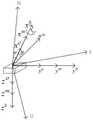
图2为本发明实施例一提供的传感器安装以及弹体姿态示意图。FIG. 2 is a schematic diagram of the sensor installation and the attitude of the missile body according to the first embodiment of the present invention.
图3为本发明实施例一提供的前期标定流程图。FIG. 3 is a flow chart of early calibration provided by
图4为本发明实施例一提供的后期标定流程图。FIG. 4 is a flowchart of a later calibration provided by
具体实施方式Detailed ways
为使本领域的技术人员更好地理解本发明的技术方案,下面结合附图对本发明提供的基于陀螺仪及磁传感器融合的背景磁场标定方法进行详细描述。In order for those skilled in the art to better understand the technical solutions of the present invention, the method for calibrating a background magnetic field based on fusion of a gyroscope and a magnetic sensor provided by the present invention will be described in detail below with reference to the accompanying drawings.
实施例一Example 1
本实施例假设三轴磁传感器安装在弹体内,其安装点处于弹体质心,使磁阻传感器的三个轴与陀螺仪坐标系、弹体坐标系的三轴平行而且方向一致。图1为本发明实施例一提供的算法流程图。如图1所示,当地地磁分量He=[HN,HE,HZ]T,磁传感器测量分量为
前期和后期的判定取决于是选取陀螺仪和当地地磁场解算出来的HM还是选取磁传感器测出的HM。设置判定函数为Ω(t),其与陀螺仪精度、磁传感器精度以及它们的测量误差等因素相关,可以结合这些因素自行设定。当t<Ω(t)时,采用陀螺仪测姿解算出的Hb对背景磁场进行标定,当t>Ω(t)时,采用磁传感器测出的HM对背景磁场进行标定。The early and late judgments depend on whether to select the HM calculated by the gyroscope and the local geomagnetic field or the HM measured by the magnetic sensor. The decision function is set as Ω(t), which is related to factors such as the accuracy of the gyroscope, the accuracy of the magnetic sensor, and their measurement errors, and can be set by themselves in combination with these factors. When t<Ω(t), the background magnetic field is calibrated with Hb calculated from the attitude measurement of the gyroscope. When t>Ω(t), the background magnetic field is calibrated with HM measured by the magnetic sensor.
图2为本发明实施例一提供的传感器安装以及弹体姿态示意图。如图2所示,将三轴磁传感器安装在弹体内,其安装点处于弹体质心,使磁阻传感器的三个轴与陀螺仪坐标系、弹体坐标系的三轴平行且方向一致。所述质心即为图2所示载体坐标系的原点,三个敏感轴分别沿弹体坐标系三坐标轴xb,yb,zb,陀螺仪三轴为xo,yo,zo。磁传感器三轴xm,ym,zm上的测量值是地磁场在载体坐标系三轴上的分量,用
根据坐标系旋转原理和地磁场,在弹体坐标系三轴上地磁分量可表示为:According to the rotation principle of the coordinate system and the geomagnetic field, the geomagnetic component on the three axes of the missile coordinate system can be expressed as:

其中,D为当地的地磁偏角,BH、BZ分别为弹体所在空间地磁场的水平分量和垂向分量,在利用地磁场进行导航和姿态测试的参考标准时,需要根据具体的情况选择合适的地磁模型计算得到地磁场要素,以此来得到参考标准。在计算中国区域地磁要素时,可以利用IGRF12、WMM2015模型或者中国地磁模型资料。Among them, D is the local geomagnetic declination, BH and BZ are the horizontal and vertical components of the geomagnetic field in the space where the projectile is located, respectively. When using the geomagnetic field for navigation and attitude testing, the reference standard needs to be selected according to the specific situation. A suitable geomagnetic model calculates the geomagnetic field elements to obtain the reference standard. When calculating the geomagnetic elements in China, the IGRF12, WMM2015 model or China geomagnetic model data can be used.
将导航坐标系转到弹体坐标系,计算公式如下:Transfer the navigation coordinate system to the missile coordinate system, and the calculation formula is as follows:

整理公式(2)可以获得:Arranging formula (2) can get:

由图2可知,本实施例前期使用陀螺仪测出载体的姿态角,直接给出当地地磁分量He=[HN,HE,HZ]T,根据陀螺仪初始装定的姿态角γ0,θ0,ψ0,陀螺仪测出的姿态角为γ,θ,ψ,利用公式(1)解算到载体坐标系Hb,Hb=HM。结合当地磁场强度He,根据公式(8)进行标定。后期陀螺仪误差较大时,采用磁传感器测量值HM和当地磁场强度He进行标定。It can be seen from Fig. 2 that in the early stage of this embodiment, the gyroscope is used to measure the attitude angle of the carrier, and the localgeomagnetic component He = [HN ,HE , HZ ]T is directly given. According to the attitude angle γ initially set by the gyroscope0 , θ0 , ψ0 , the attitude angles measured by the gyroscope are γ, θ, ψ, which are calculated to the carrier coordinate system Hb by formula (1), whereHb =HM . Combined with the local magnetic field strength He, the calibration isperformed according to formula (8). When the gyroscope error is large in the later stage, the measurement value HM of the magnetic sensor and the local magnetic field strength He areused for calibration.
前期和后期的判定取决于是选取陀螺仪和当地地磁场解算出来的HM还是选取磁传感器测出的HM。本实施例设置判定函数为Ω(t),其与陀螺仪精度,磁传感器精度以及它们的测量误差等因素相关,可结合这些因素自行设定。当t<Ω(t)时,采用陀螺仪测姿解算出的Hb对背景磁场进行标定,当t>Ω(t)时,采用磁传感器测出的HM对背景磁场进行标定。The early and late judgments depend on whether to select the HM calculated by the gyroscope and the local geomagnetic field or the HM measured by the magnetic sensor. In this embodiment, the determination function is set as Ω(t), which is related to factors such as the accuracy of the gyroscope, the accuracy of the magnetic sensor, and their measurement errors, and can be set by themselves in combination with these factors. When t<Ω(t), the background magnetic field is calibrated with Hb calculated from the attitude measurement of the gyroscope. When t>Ω(t), the background magnetic field is calibrated with HM measured by the magnetic sensor.
地球上某固定点处,在没有背景磁场干扰下,磁传感器的测值量为当地地磁矢量He,满足如下公式:At a fixed point on the earth, without the interference of the background magnetic field, the measured value of the magnetic sensor is the localgeomagnetic vector He, which satisfies the following formula:
||He||2=(He)THe (4)||He ||2 =(He )THe ( 4)
将地磁场的三分量代入公式(4)获得公式(5),计算公式如下:Substitute the three components of the geomagnetic field into formula (4) to obtain formula (5), and the calculation formula is as follows:
(Hex)2+(Hey)2+(Hez)2=||He||2 (5)(Hex )2 +(Hey )2 +(Hez )2 =||He ||2 (5)
对于磁测量而言,背景磁场就是指除目标磁场外的其他干扰磁场。通常意义下,背景磁场主要包括弹体产生的固定磁场、磁化感应磁场、涡流磁场。弹体背景磁场在磁传感器测量坐标系下的总模型为:对于利用地磁来测量弹体姿态而言,背景磁场是除地磁场分量外的所有干扰磁场。本实施例获得磁传感器测量的磁场强度为:For magnetic measurement, the background magnetic field refers to other interfering magnetic fields other than the target magnetic field. Generally speaking, the background magnetic field mainly includes the fixed magnetic field, magnetization induced magnetic field and eddy current magnetic field generated by the projectile. The overall model of the background magnetic field of the projectile in the magnetic sensor measurement coordinate system is: for measuring the attitude of the projectile by using the geomagnetism, the background magnetic field is all the disturbance magnetic fields except the geomagnetic field component. The magnetic field intensity measured by the magnetic sensor obtained in this embodiment is:

其中,


将公式(6)扩展成矩阵形式,计算公式如下:Extending formula (6) into matrix form, the calculation formula is as follows:

本实施例前期利用陀螺仪测出载体的姿态角,解算出三轴磁传感器在弹体坐标轴的三分量,后期利用三轴磁传感器实测的磁场强度在弹体坐标轴的三分量,经过下面公式所示的模型化补偿过程求得目标地磁场在弹体坐标轴的三分量。目标地磁场在弹体坐标系的三分量为:In this embodiment, the attitude angle of the carrier is measured by the gyroscope in the early stage, and the three components of the three-axis magnetic sensor on the coordinate axis of the projectile body are calculated. The modeled compensation process shown in the formula obtains the three components of the target geomagnetic field in the coordinate axis of the projectile. The three components of the target geomagnetic field in the projectile coordinate system are:

将公式(8)扩展成矩阵形式,计算公式如下:Extending formula (8) into matrix form, the calculation formula is as follows:

上式是一个待定常系数六元一次方程组,其中每个方程都是一个包含7个未知系数的六元一次线性方程,而且相互独立。背景磁场补偿就是求取上述方程组21个待定常系数。The above formula is a system of six-variable linear equations with undetermined constant coefficients, each of which is a six-variable linear equation containing 7 unknown coefficients, and is independent of each other. Background magnetic field compensation is to obtain the 21 undetermined constant coefficients of the above equations.
本实施例空中自标定背景磁场分为两个部分,在炮弹发射出去的前期采用陀螺仪标定磁场,后期采用磁传感器标定。由于陀螺仪在姿态测量的初期具有较高的可靠性、算法简单且精度高的特性,后期随着时间的增加,测量误差越来越大,所以前期采用陀螺仪标定,可提高测量精度,从而降低标定误差,后期再采用磁传感器标定。In this embodiment, the air self-calibration background magnetic field is divided into two parts. The gyroscope is used to calibrate the magnetic field in the early stage when the projectile is launched, and the magnetic sensor is used to calibrate the magnetic sensor in the later stage. Since the gyroscope has the characteristics of high reliability, simple algorithm and high precision in the initial attitude measurement, the measurement error becomes larger and larger with the increase of time in the later stage. Therefore, the gyroscope calibration is used in the early stage to improve the measurement accuracy, thereby To reduce the calibration error, the magnetic sensor is used for calibration later.
当数据点的数目为n时,


①对弹体固定磁场和磁化感应磁场进行标定。①Calibrate the fixed magnetic field and magnetization-induced magnetic field of the projectile.
②对弹体的涡流磁场进行标定。② Calibrate the eddy current magnetic field of the projectile.
图3为本发明实施例一提供的前期标定流程图。如图3所示,前期陀螺仪的精度较高,利用陀螺仪解算出的和陀螺仪测出的姿态角分别对①、②进行标定。图4为本发明实施例一提供的后期标定流程图。如图4所示,后期利用磁传感器测出的HM及其解算出的姿态角分别对①、②进行标定。FIG. 3 is a flow chart of early calibration provided by
当弹体处于角运动状态下,具有较高的姿态角速度时,涡流磁场干扰EHe′无法直接从传感器的输出中得到,本实施例首先利用椭球拟合法算出固定磁场和磁化感应磁场的补偿系数并结合公式(10)的输出模型算出传感器输出之中固定磁场和磁化感应磁场的干扰分量,再通过式(11)将涡流磁场干扰分量分离出来,分别对①、②进行标定,计算公式如下:When the projectile is in angular motion and has a high attitude angular velocity, the eddy current magnetic field interference EHe' cannot be directly obtained from the output of the sensor. In this embodiment, the ellipsoid fitting method is used to calculate the compensation of the fixed magnetic field and the magnetization-induced magnetic field. The coefficient and the output model of formula (10) are used to calculate the interference components of the fixed magnetic field and the magnetization induced magnetic field in the sensor output, and then the eddy current magnetic field interference components are separated by formula (11), and ① and ② are calibrated respectively. The calculation formula is as follows :


本实施例对固定磁场和磁化感应磁场进行标定。前期先用陀螺仪测出载体的姿态角,直接给出当地地磁分量He=[HN,HE,HZ]T,根据陀螺仪初始装定的姿态角γ0,θ0,ψ0,陀螺仪测出的姿态角为γ,θ,ψ,利用公式(1)解算到载体坐标系Hb,Hb=HM,再结合当地磁场强度He,根据公式(10)利用椭球拟合法对弹体固定磁场
本实施例对涡流磁场进行标定。涡流磁场

其中,γ,θ,ψ为由陀螺仪测出载体的姿态角,He为当地地磁场强度。对公式(12)的等号两边同时求导,获得地磁场在所述弹体坐标系的三分量的变化率,计算公式如下:Among them, γ, θ,ψ are the attitude angles of the carrier measured by the gyroscope, and He is the local geomagnetic field strength. Simultaneously derive the two sides of the equal sign of formula (12) to obtain the rate of change of the three components of the earth's magnetic field in the projectile coordinate system. The calculation formula is as follows:

本实施例使用公式(1)解算到载体坐标系Hb,Hb=HM,结合当地磁场强度He,根据公式(11)使用公式(14)的涡流磁场模型对涡流磁场进行标定,计算公式如下:In this embodiment, formula (1) is used to solve the carrier coordinate system Hb ,Hb =HM , and the eddy current magnetic field is calibrated according to formula (11) using the eddy current magnetic field model of formula (14) in combination with the local magnetic field strength He , Calculated as follows:

后期陀螺仪误差较大时,本实施例使用磁传感器测量值HM和其解算出的姿态角分别对①、②进行标定。对于大多数的常规弹药的距离变化,在炮兵标准气象条件下,航向角变化很小。姿态解算时可将航向角ψ近似看为前一时刻(k-1)前期标定时陀螺仪解算出的航向角ψ,即ψ(k)=ψ(k-1)。俯仰角θ和横滚角γ,可以通过公式(15)求解。根据公式(3)使用公式(15)解算出姿态角γ,θ,ψ。根据公式(10)利用椭球拟合法对弹体固定磁场
已知ψ(k)=ψ(k-1),公式(3)第二式可以写成公式(15)的形式,求得当前时刻(k)的俯仰角θ(k)。公式(3)第一式可以写成公式(16)的形式,求得当前时刻(k)的俯仰角θ(k)。公式(3)第一式可以写成公式(17)的形式,求得当前时刻(k)的横滚角γ(k),计算公式如下:Knowing that ψ(k)=ψ(k-1), the second formula of formula (3) can be written in the form of formula (15) to obtain the pitch angle θ(k) at the current moment (k). The first formula of formula (3) can be written in the form of formula (16) to obtain the pitch angle θ(k) at the current moment (k). The first formula of formula (3) can be written in the form of formula (17) to obtain the roll angle γ(k) at the current moment (k), and the calculation formula is as follows:


本实施例提供的基于陀螺仪及磁传感器融合的背景磁场标定方法,包括:将磁传感器安装在弹体之内,所述磁传感器的安装点位于所述弹体的质心,以使所述磁传感器的三个轴分别与陀螺仪坐标系的三个坐标轴、弹体坐标系的三个坐标轴平行而且方向一致,使用陀螺仪测量载体的姿态角,根据所述陀螺仪初始状态的姿态角以及所述陀螺仪测量的姿态角计算载体坐标系,获得磁传感器测量的磁场强度,前期使用所述陀螺仪测算的磁场强度对背景磁场进行标定,后期使用所述磁传感器测算的磁场强度对背景磁场进行标定。本实施例提供的陀螺姿态测量技术能够解决地磁姿态测量不能独立求解的问题,而且陀螺仪在姿态测量之中具有可靠性高、解算算法简单和测量精度高的优势。因此,本实施例提供的基于陀螺仪及磁传感器融合的背景磁场标定方法,能够有效提高背景磁场的标定精度。The method for calibrating a background magnetic field based on the fusion of a gyroscope and a magnetic sensor provided in this embodiment includes: installing a magnetic sensor in a projectile, and the installation point of the magnetic sensor is located at the center of mass of the projectile, so that the magnetic The three axes of the sensor are respectively parallel to the three coordinate axes of the gyroscope coordinate system and the three coordinate axes of the projectile coordinate system and have the same direction. The gyroscope is used to measure the attitude angle of the carrier, according to the attitude angle of the initial state of the gyroscope. And the attitude angle measured by the gyroscope calculates the carrier coordinate system, obtains the magnetic field intensity measured by the magnetic sensor, uses the magnetic field intensity measured by the gyroscope in the early stage to calibrate the background magnetic field, and uses the magnetic field intensity measured by the magnetic sensor in the later stage to calibrate the background magnetic field. Magnetic field calibration. The gyro attitude measurement technology provided by this embodiment can solve the problem that the geomagnetic attitude measurement cannot be solved independently, and the gyro has the advantages of high reliability, simple calculation algorithm and high measurement accuracy in attitude measurement. Therefore, the background magnetic field calibration method based on the fusion of the gyroscope and the magnetic sensor provided in this embodiment can effectively improve the calibration accuracy of the background magnetic field.
可以理解的是,以上实施方式仅仅是为了说明本发明的原理而采用的示例性实施方式,然而本发明并不局限于此。对于本领域内的普通技术人员而言,在不脱离本发明的精神和实质的情况下,可以做出各种变型和改进,这些变型和改进也视为本发明的保护范围。It can be understood that the above embodiments are only exemplary embodiments adopted to illustrate the principle of the present invention, but the present invention is not limited thereto. For those skilled in the art, without departing from the spirit and essence of the present invention, various modifications and improvements can be made, and these modifications and improvements are also regarded as the protection scope of the present invention.
Claims (6)


Priority Applications (1)
| Application Number | Priority Date | Filing Date | Title |
|---|---|---|---|
| CN201911127010.0ACN110736484B (en) | 2019-11-18 | 2019-11-18 | Calibration method of background magnetic field based on fusion of gyroscope and magnetic sensor |
Applications Claiming Priority (1)
| Application Number | Priority Date | Filing Date | Title |
|---|---|---|---|
| CN201911127010.0ACN110736484B (en) | 2019-11-18 | 2019-11-18 | Calibration method of background magnetic field based on fusion of gyroscope and magnetic sensor |
Publications (2)
| Publication Number | Publication Date |
|---|---|
| CN110736484A CN110736484A (en) | 2020-01-31 |
| CN110736484Btrue CN110736484B (en) | 2021-06-08 |
Family
ID=69273100
Family Applications (1)
| Application Number | Title | Priority Date | Filing Date |
|---|---|---|---|
| CN201911127010.0AActiveCN110736484B (en) | 2019-11-18 | 2019-11-18 | Calibration method of background magnetic field based on fusion of gyroscope and magnetic sensor |
Country Status (1)
| Country | Link |
|---|---|
| CN (1) | CN110736484B (en) |
Families Citing this family (4)
| Publication number | Priority date | Publication date | Assignee | Title |
|---|---|---|---|---|
| CN113466765B (en)* | 2020-03-31 | 2024-12-10 | 通用电气精准医疗有限责任公司 | Magnetic resonance scanning method and system, and computer readable storage medium |
| CN112034402B (en)* | 2020-07-16 | 2021-12-28 | 中国人民解放军军事科学院国防科技创新研究院 | Combined calibration method for remanence and remanence moment of micro-nano satellite |
| CN112284377A (en)* | 2020-10-27 | 2021-01-29 | 中国人民解放军海军工程大学 | A geomagnetic field measurement system and method applied to aircraft |
| CN112833917B (en)* | 2021-01-27 | 2022-09-16 | 北京航空航天大学 | Three-axis magnetic sensor calibration method based on magnetic course angle and least square method |
Citations (3)
| Publication number | Priority date | Publication date | Assignee | Title |
|---|---|---|---|---|
| CN106959336A (en)* | 2016-01-11 | 2017-07-18 | 宝山钢铁股份有限公司 | The ambient noise removal device and method demarcated for Magnetic Flux Leakage Inspecting |
| CN108267157A (en)* | 2018-03-21 | 2018-07-10 | 歌尔股份有限公司 | The calibration method and calibrating installation of geomagnetic sensor |
| CN110031020A (en)* | 2019-03-28 | 2019-07-19 | 广州英卓电子科技有限公司 | A kind of flat magnetic field bearing calibration and its device |
Family Cites Families (1)
| Publication number | Priority date | Publication date | Assignee | Title |
|---|---|---|---|---|
| JP6104169B2 (en)* | 2010-11-08 | 2017-03-29 | クアルコム,インコーポレイテッド | Device and method for gyro sensor calibration |
- 2019
- 2019-11-18CNCN201911127010.0Apatent/CN110736484B/enactiveActive
Patent Citations (3)
| Publication number | Priority date | Publication date | Assignee | Title |
|---|---|---|---|---|
| CN106959336A (en)* | 2016-01-11 | 2017-07-18 | 宝山钢铁股份有限公司 | The ambient noise removal device and method demarcated for Magnetic Flux Leakage Inspecting |
| CN108267157A (en)* | 2018-03-21 | 2018-07-10 | 歌尔股份有限公司 | The calibration method and calibrating installation of geomagnetic sensor |
| CN110031020A (en)* | 2019-03-28 | 2019-07-19 | 广州英卓电子科技有限公司 | A kind of flat magnetic field bearing calibration and its device |
Non-Patent Citations (1)
| Title |
|---|
| 基于自包含传感器的单兵导航系统设计;田晓春等;《导航定位与授时》;20170930;第54-59页* |
Also Published As
| Publication number | Publication date |
|---|---|
| CN110736484A (en) | 2020-01-31 |
Similar Documents
| Publication | Publication Date | Title |
|---|---|---|
| CN110736484B (en) | Calibration method of background magnetic field based on fusion of gyroscope and magnetic sensor | |
| CN107314718B (en) | High speed rotation bullet Attitude estimation method based on magnetic survey rolling angular rate information | |
| CN107272069B (en) | Magnetic target tracking method based on magnetic anomalous gradient | |
| CN107289933B (en) | Double Kalman filter navigation device and method based on MEMS sensor and VLC positioning fusion | |
| CN103196445B (en) | Based on the carrier posture measuring method of the earth magnetism supplementary inertial of matching technique | |
| CN103743413B (en) | Heeling condition modulated is sought northern instrument alignment error On-line Estimation and is sought northern error compensating method | |
| CN102901977B (en) | Method for determining initial attitude angle of aircraft | |
| CN107063254B (en) | Gesture resolving method for gyros and geomagnetic combination | |
| CN107894241A (en) | A kind of unmanned plane magnetic sensor calibration method, unmanned plane based on ellipsoid fitting | |
| CN108458714A (en) | The Eulerian angles method for solving of acceleration of gravity is free of in a kind of attitude detection system | |
| CN107270898B (en) | Dual particle filter navigation device and method based on MEMS sensor and VLC positioning fusion | |
| CN115096294B (en) | Multi-parameter underwater magnetic target positioning method | |
| CN106017452A (en) | Dual gyro anti-disturbance north-seeking method | |
| CN105910606A (en) | Direction adjustment method based on angular velocity difference | |
| CN107894235A (en) | A model error compensation method for autonomous navigation system of ultra-high-speed aircraft | |
| CN110440746A (en) | A kind of no-dig technique subterranean drill bit posture fusion method based on the decline of quaternary number gradient | |
| Chen et al. | An improved geomagnetic navigation method based on two-component gradient weighting | |
| CN110017808B (en) | Method for resolving aircraft attitude by using geomagnetic information and accelerometer | |
| CN110017830B (en) | Method for resolving aircraft attitude by using geomagnetic information and gravity sensor | |
| CN110044321A (en) | The method for resolving attitude of flight vehicle using Geomagnetism Information and angular rate gyroscope | |
| CN110030991B (en) | High-speed rotation angle movement measuring method for flyer integrating gyroscope and magnetometer | |
| Zhao et al. | Magnetometer-based phase shifting ratio method for high spinning projectile’s attitude measurement | |
| CN110160519A (en) | Projectile body posture calculation method for pulse correction rocket projectile | |
| CN110986926B (en) | Flight projectile body rotation attitude measurement method based on geomagnetic elements | |
| CN109931956A (en) | Three-axis magnetometer and inertial navigation installation error correction method in strapdown three-component magnetic measurement system |
Legal Events
| Date | Code | Title | Description |
|---|---|---|---|
| PB01 | Publication | ||
| PB01 | Publication | ||
| SE01 | Entry into force of request for substantive examination | ||
| SE01 | Entry into force of request for substantive examination | ||
| GR01 | Patent grant | ||
| GR01 | Patent grant |