CN110733034B - Robotic arm calibration method, robotic arm calibration system and conveying system - Google Patents
Robotic arm calibration method, robotic arm calibration system and conveying systemDownload PDFInfo
- Publication number
- CN110733034B CN110733034BCN201810804854.3ACN201810804854ACN110733034BCN 110733034 BCN110733034 BCN 110733034BCN 201810804854 ACN201810804854 ACN 201810804854ACN 110733034 BCN110733034 BCN 110733034B
- Authority
- CN
- China
- Prior art keywords
- parameter
- error value
- control circuit
- image
- robotic arm
- Prior art date
- Legal status (The legal status is an assumption and is not a legal conclusion. Google has not performed a legal analysis and makes no representation as to the accuracy of the status listed.)
- Active
Links
Images


Classifications
- B—PERFORMING OPERATIONS; TRANSPORTING
- B25—HAND TOOLS; PORTABLE POWER-DRIVEN TOOLS; MANIPULATORS
- B25J—MANIPULATORS; CHAMBERS PROVIDED WITH MANIPULATION DEVICES
- B25J9/00—Programme-controlled manipulators
- B25J9/16—Programme controls
- B25J9/1679—Programme controls characterised by the tasks executed
- B25J9/1692—Calibration of manipulator
Landscapes
- Engineering & Computer Science (AREA)
- Robotics (AREA)
- Mechanical Engineering (AREA)
- Manipulator (AREA)
Abstract
Description
Translated fromChinese技术领域technical field
本发明涉及一种机械手臂校正方法以及其系统,特别涉及一种通过两个感光耦合元件取得对应于不同位置的校正图案影像以执行机械手臂的校正的机械手臂校正方法以及其系统。The present invention relates to a method for calibrating a robot arm and a system thereof, in particular to a method for calibrating a robot arm and a system thereof for obtaining calibration pattern images corresponding to different positions through two photosensitive coupling elements to perform the calibration of the robot arm.
背景技术Background technique
一般而言,当进行机械手臂与输送带的校正时,通常必须通过人眼观察目前机械手臂的追踪情况,再根据过往经验对特定参数进行调整,以对机械手臂的误差进行校正。然而,由于此方法需要经过长时间的观察,且必须依赖过往经验才可有效率地对机械手臂以及输送带的相对关系进行校正,如此将耗费许多时间以及人力,且调整经验将不容易被复制传承。因此如何更有效率地且更快速地对机械手臂进行校正为目前必须解决的问题。Generally speaking, when calibrating the robot arm and the conveyor belt, it is usually necessary to observe the current tracking situation of the robot arm through the human eye, and then adjust specific parameters based on past experience to correct the error of the robot arm. However, since this method requires a long period of observation and must rely on past experience to efficiently calibrate the relative relationship between the robotic arm and the conveyor belt, it will take a lot of time and manpower, and the adjustment experience will not be easily replicated inherited. Therefore, how to calibrate the robotic arm more efficiently and quickly is a problem that must be solved at present.
发明内容SUMMARY OF THE INVENTION
本发明一实施例提供一种机械手臂校正方法,包括:根据多个当前运作参数驱动一输送系统的一输送带以及一机械手臂;通过一第一感光耦合元件于输送带的一第一区域取得对应于一校正图案的一第一影像;通过设置于机械手臂上的一第二感光耦合元件于输送带的一第二区域取得对应于校正图案的一第二影像;通过一控制电路根据第一影像、第二影像以及当前运作参数取得对应于校正图案的多个参数误差值;通过控制电路根据参数误差值校正当前运作参数,并取得多个校正后的运作参数;以及根据校正后的运作参数重新取得对应于校正图案的第一影像以及第二影像。An embodiment of the present invention provides a method for calibrating a robotic arm, including: driving a conveyor belt and a robotic arm of a conveying system according to a plurality of current operating parameters; A first image corresponding to a calibration pattern; a second image corresponding to the calibration pattern is obtained from a second area of the conveyor belt through a second photosensitive coupling element disposed on the robotic arm; a control circuit is used to obtain a second image corresponding to the calibration pattern according to the first The image, the second image and the current operation parameters obtain a plurality of parameter error values corresponding to the calibration pattern; correct the current operation parameters according to the parameter error values through the control circuit, and obtain a plurality of corrected operation parameters; and according to the corrected operation parameters Reacquire the first image and the second image corresponding to the calibration pattern.
本发明另一实施例更提供一种机械手臂校正系统,包括一第一感光耦合元件、一第二感光耦合元件以及一控制电路。第一感光耦合元件设置于一输送系统的一输送带的一第一区域上方,用以于第一区域取得对应于一校正图案的一第一影像。第二感光耦合元件设置于输送系统的一机械手臂上,用以于输送带的一第二区域取得对应于校正图案的一第二影像。控制电路根据第一影像、第二影像以及多个当前运作参数取得对应于校正图案的多个参数误差值,根据参数误差值校正当前运作参数,取得多个校正后的运作参数,以及根据校正后的运作参数重新驱动输送带以及机械手臂。于控制单元根据校正后的运作参数重新驱动输送带以及机械手臂后,第一感光耦合元件以及第二感光耦合元件重新取得对应于校正图案的第一影像以及第二影像。Another embodiment of the present invention further provides a robotic arm calibration system, which includes a first photosensitive coupling element, a second photosensitive coupling element, and a control circuit. The first photosensitive coupling element is disposed above a first area of a conveyor belt of a conveying system, and is used for obtaining a first image corresponding to a calibration pattern in the first area. The second photosensitive coupling element is disposed on a mechanical arm of the conveying system, and is used for obtaining a second image corresponding to the calibration pattern in a second area of the conveying belt. The control circuit obtains a plurality of parameter error values corresponding to the calibration pattern according to the first image, the second image and the plurality of current operation parameters, corrects the current operation parameters according to the parameter error values, obtains a plurality of corrected operation parameters, and The operating parameters re-drive the conveyor belt as well as the robotic arm. After the control unit re-drives the conveyor belt and the manipulator according to the corrected operation parameters, the first photosensitive coupling element and the second photosensitive coupling element obtain the first image and the second image corresponding to the calibration pattern again.
本发明另一实施例更提供一种输送系统,包括一输送带、一编码器、一机械手臂、一第一感光耦合元件、一第二感光耦合元件、一第一控制电路以及一第二控制电路。输送带用以导载至少一校正图案。编码器用以带动输送带。机械手臂用以执行至少一校正作业。第一感光耦合元件设置于输送带的一第一区域上方,用以于第一区域取得对应于一校正图案的一第一影像。第二感光耦合元件设置于机械手臂上,用以于输送带的一第二区域取得对应于校正图案的一第二影像。第一控制电路根据第一影像、第二影像以及多个当前运作参数取得对应于校正图案的多个参数误差值,以及根据参数误差值校正当前运作参数,并产生多个校正后的运作参数。第二控制电路根据当前运作参数或者校正后的运作参数产生对应于校正作业的一驱动信号,并根据驱动信号驱动机械手臂以及编码器。于第二控制单元根据校正后的运作参数重新驱动机械手臂以及编码器后,第一感光耦合元件以及第二感光耦合元件重新取得对应于校正图案的第一影像以及第二影像,第一控制单元重新根据第一影像以及第二影像校正当前运作参数,直到对应于校正图案的多个参数误差值皆小于一既定值为止。Another embodiment of the present invention further provides a conveying system including a conveying belt, an encoder, a robotic arm, a first photosensitive coupling element, a second photosensitive coupling element, a first control circuit, and a second control circuit. The conveyor belt is used for carrying at least one calibration pattern. The encoder is used to drive the conveyor belt. The robotic arm is used for performing at least one calibration operation. The first photosensitive coupling element is disposed above a first area of the conveyor belt, and is used for obtaining a first image corresponding to a calibration pattern in the first area. The second photosensitive coupling element is disposed on the robot arm, and is used for obtaining a second image corresponding to the calibration pattern in a second area of the conveyor belt. The first control circuit obtains a plurality of parameter error values corresponding to the calibration pattern according to the first image, the second image and the plurality of current operation parameters, corrects the current operation parameters according to the parameter error values, and generates a plurality of corrected operation parameters. The second control circuit generates a drive signal corresponding to the calibration operation according to the current operation parameter or the corrected operation parameter, and drives the robot arm and the encoder according to the drive signal. After the second control unit re-drives the manipulator and the encoder according to the corrected operating parameters, the first photosensitive coupling element and the second photosensitive coupling element obtain the first image and the second image corresponding to the calibration pattern again, the first control unit The current operating parameters are re-calibrated according to the first image and the second image until the error values of the parameters corresponding to the calibration pattern are all smaller than a predetermined value.
附图说明Description of drawings
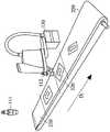
图1是显示根据本发明一实施例所述的具有机械手臂校正系统的输送系统的架构图。FIG. 1 is a schematic diagram illustrating a conveying system with a robotic arm calibration system according to an embodiment of the present invention.
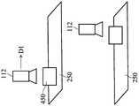
图2是显示根据本发明一实施例所述的具有机械手臂校正系统的输送系统的示意图。FIG. 2 is a schematic diagram showing a delivery system with a robotic arm calibration system according to an embodiment of the present invention.
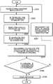
图3是显示根据本发明一实施例所述的机械手臂校正方法的流程图。FIG. 3 is a flowchart illustrating a method for calibrating a robotic arm according to an embodiment of the present invention.
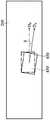
图4、5是显示根据本发明一些实施例所述的工件(或者校正图案)的理想运作状态的示意图。4 and 5 are schematic diagrams showing ideal operating states of the workpiece (or calibration pattern) according to some embodiments of the present invention.
图6~8是显示根据本发明一些实施例所述的工件(或者校正图案)的实际运作状态的示意图。6-8 are schematic diagrams showing the actual operation states of the workpiece (or calibration pattern) according to some embodiments of the present invention.
图9是显示根据本发明一实施例所述的对应于第一区域的校正图案的第一影像的示意图。FIG. 9 is a schematic diagram showing a first image of a calibration pattern corresponding to a first region according to an embodiment of the present invention.
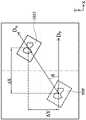
图10A~10C是显示根据本发明一些实施例所述的在不同状况下校正图案的实际位置与预测位置的差异的示意图。10A-10C are schematic diagrams showing the difference between the actual position and the predicted position of the calibration pattern under different conditions according to some embodiments of the present invention.
附图标记说明:Description of reference numbers:
Δx~水平误差Δx~horizontal error
Δy~垂直误差Δy~vertical error
θ~角度误差θ~Angle error
100~输送系统100~Conveying system
1051~1053~位于实际位置的校正图案1051~1053~Calibration pattern at actual position
110~机械手臂校正系统110~Robot calibration system
111~第一感光耦合元件111~The first photosensitive coupling element
112~第二感光耦合元件112~Second photosensitive coupling element
113~第一控制电路113~The first control circuit
120~第二控制电路120~Second control circuit
130~机械手臂130~Robot arm
140~编码器140~encoder
210~第一感光耦合元件所对应的区域210~The area corresponding to the first photosensitive coupling element
220~第二感光耦合元件所对应的区域220~The area corresponding to the second photosensitive coupling element
450~工件/校正图案的实际位置450 to actual position of workpiece/calibration pattern
450’~工件/校正图案的预测位置450'~Predicted position of workpiece/calibration pattern
801~校正图案的中心点801~Center point of calibration pattern
850~校正图案850~Calibration pattern
950’~位于预测位置的校正图案950’~Calibration pattern at predicted position
D1~输送带的输送方向D1 ~The conveying direction of the conveyor belt
DA~实际移动向量DA ~actual motion vector
DP~预测移动向量DP ~ predicted motion vector
S301~S308~步骤流程S301~S308~Step Flow
具体实施方式Detailed ways
有关本发明的机械手臂校正方法、机械手臂校正系统以及输送系统适用的其他范围将于接下来所提供的详述中清楚易见。必须了解的是下列的详述以及具体的实施例,当提出有关机械手臂校正方法、机械手臂校正系统以及输送系统的示范实施例时,仅作为描述的目的以及并非用以限制本发明的范围。Other scopes applicable to the robotic arm calibration method, robotic arm calibration system, and delivery system of the present invention will become apparent from the detailed description provided below. It must be understood that the following detailed description and specific examples, while presenting exemplary embodiments of the robotic arm calibration method, robotic arm calibration system, and delivery system, are for descriptive purposes only and are not intended to limit the scope of the invention.
图1是显示根据本发明一实施例所述的具有机械手臂校正系统的输送系统的系统架构图。输送系统100包括机械手臂校正系统110、第二控制电路120、机械手臂130以及编码器140。机械手臂校正系统110包括一第一感光耦合元件(CCD)111、一第二感光耦合元件112以及一第一控制电路113。第一感光耦合元件111以及第二感光耦合元件112分别于一输送系统100的一输送带上的不同位置上撷取对应于一工件(或者至少一校正图案)的影像。其中,第二感光耦合元件112是设置于输送系统100的一机械手臂130上。换言之,第二感光耦合元件112会随着机械手臂130移动,并拍摄对应于机械手臂130的作业范围内的影像。第一控制电路113接收第一感光耦合元件111以及第二感光耦合元件112所取得的影像,根据所取得影像以及对应于输送系统100的当前运作参数(例如输送带的输送速度、机械手臂130与输送带250的相对位置以及角度等)执行相关的计算,并根据计算结果决定是否对输送系统100的当前运作参数进行校正。其中,运作参数可包括编码器140的相关参数(与输送带的输送速度相关)、机械手臂130的偏移参数以及工件(或者校正图案)移动的方向向量等。此外,第一控制电路113可通过多种方式实施,例如以专用硬件电路或者通用硬件(例如,单一处理器、具平行处理能力的多处理器、图形处理器或者其它具有运算能力的处理器),以执行与本发明的校正流程相关的程序码或者软件。此外,机械手臂校正系统110更可包括一储存单元(未显示),用以暂存对应于校正图案的影像以及运作参数等,以供第一控制电路113进行存取。FIG. 1 is a system architecture diagram showing a conveying system with a robotic arm calibration system according to an embodiment of the present invention. The
第二控制电路120用以根据当前运作参数产生对应于一校正作业或者一加工作业的一驱动信号来驱动机械手臂130以及编码器140,以同时带动输送带250以及致能机械手臂130执行校正作业或者加工作业。其中,第二控制电路120可通过多种方式实施,例如以专用硬件电路或者通用硬件(例如,单一处理器、具平行处理能力的多处理器或者其它具有运算能力的处理器)。值得注意的是,第一控制电路113以及第二控制电路120亦可整合于同一个控制电路上,即该控制电路可执行运作参数的相关校正并可同时根据当前运作参数产生驱动机械手臂130以及编码器140的驱动信号。此外,输送系统100亦可包括另一储存单元(未显示),用以储存前述的当前运作参数以及相关的运算公式,以供第二控制电路120进行存取。The
图2是显示根据本发明一实施例所述的机械手臂校正系统110的示意图。如图2所示,校正图案是沿着输送带250的一输送方向D1移动。第一感光耦合元件111设置于输送带250的前端,用以取得第一区域210内对应于工件或者校正图案的影像(第一影像)。接着,当校正图案进入机械手臂130的作业范围(即第二区域220)中时,第二感光耦合元件112取得对应于工件或者校正图案的至少一第二影像。值得注意的是,由于机械手臂130亦会根据校正作业沿着输送方向D1前进,因此第二感光耦合元件112可于输送带250的不同位置上方取得对应于工件或者校正图案的不同影像。举例来说,当机械手臂130进行校正作业时,可每隔一既定时间通过第二感光耦合元件112取得对应于不同时间点的校正图案的多个影像。其中,所取得的对应于校正图案的影像越多,第一控制电路113可更准确地计算得校正图案与机械手臂130的相对位置关系。FIG. 2 is a schematic diagram illustrating a robotic
图3是显示根据本发明一实施例所述的机械手臂校正方法的流程图。于步骤S301,第二控制电路120根据多个当前运作参数驱动输送系统100的输送带250以及机械手臂130。于理想状态下,由于机械手臂130与输送带250的相对位置关系已事先经过计算,因此第二耦合元件112所取得的对应于工件(或者校正图案)的位置应会与根据运作参数所计算得的预测位置重叠。举例来说,图4是显示工件(或者校正图案)的理想运作状态的上视图。如图中所示,工件(或者校正图案)的预测位置450’与实际位置450于理想状态下应完全重叠。此外,图5是显示根据本发明一实施例所述的工件(或者校正图案)的理想运作状态的侧视图。如图中所示,机械手臂130的前进速度应会与工件(或者校正图案)的前进速度相同。然而,于实际情况下,输送带250以及机械手臂130的运作会因某些因素使得实际位置与预测位置产生误差,因此必须根据误差情况对运作参数进行调整。举例来说,如图6所示,由于第二感光耦合元件112(位于机械手臂130)的前进速度比工件(或者校正图案)的前进速度快,使得输送系统100在经过一段工作时间后,机械手臂130与工件(或者校正图案)的位置前后错开。或者,如图7所示,工件(或者校正图案)的预测位置450’与实际位置450具有平行于输送带250的输送方向D1的一水平误差Δx以及垂直于输送带250的输送方向D1的一垂直误差Δy(其中对应于X方向的水平误差Δx与对应于Y方向的垂直误差Δy可通过计算预测位置450’与实际位置450的中心点而求得)。或者,如图8所示,由于一些外在因素可能会造成输送带歪斜,使得工件(或者校正图案)的实际输送方向(如图中实线DA所示)与预测的输送方向(如图中虚线DP所示)产生误差,进而造成实际移动方向DA与预测移动方向DP具有一角度误差θ。FIG. 3 is a flowchart illustrating a method for calibrating a robotic arm according to an embodiment of the present invention. In step S301, the
然而,前述的误差可通过第一感光耦合元件111以及第二感光耦合元件112于两个不同位置所取得的两张不同影像求得。举例来说,于步骤S302,第一感光耦合元件111首先于位于输送带250的前端的第一位置(对应于图2中所示的区域210)取得对应于校正图案的第一影像。举例来说,如图9所示,图9是显示根据本发明一实施例所述的对应于第一区域的校正图案的第一影像的示意图。接着,于步骤S303,第一控制电路113根据第一影像以及当前运作参数取得对应于第二区域的预测位置。于步骤S304,第二感光耦合元件112于输送带250的第二位置(对应于图2中所示的区域220)取得对应于校正图案的第二影像。其中,于理想状态下,于第二区域所取得的影像应会与图9所示的第一影像相同。接着,于步骤S305,第一控制电路113即可根据预测位置以及第二影像判断误差状况。举例来说,请参阅图10A~10C,图10A~10C是显示根据本发明一些实施例所述的在不同状况下校正图案的实际位置与预测位置的差异的示意图。如图10A所示,第一控制电路113可根据位于实际位置的校正图案1051与位于预测位置的校正图案950’取得对应于X方向(即平行于输送带250的输送方向D1)的水平误差Δx(第一参数误差值)。或者,如图10B所示,第一控制电路113可根据位于实际位置的校正图案1052与位于预测位置的校正图案950’取得对应于Y方向(即垂直于输送带250的输送方向D1)的垂直误差Δy(第二参数误差值)。再者,根据图10C所示,第一控制电路113可根据对应于实际校正图案1053的实际移动方向DA与对应于原始校正图案950’的预测移动方向DP取得角度误差θ(第三参数误差值)。However, the aforementioned error can be obtained from two different images obtained by the first
接着,于步骤S306,第一控制电路113更判断第一参数误差值、第二参数误差值以及第三参数误差值是否皆小于对应的既定值,即位于可容许的误差范围内。若第一参数误差值、第二参数误差值以及第三参数误差值的任一者大于既定值时,则表示机械手臂112与输送带250的相对位置关系的误差超过可容许的范围,则进入步骤S307,第一控制电路根据第一参数误差值、第二参数误差值以及第三参数误差值校正当前运作参数,并取得校正后的运作参数。举例来说,根据本发明一实施例,当水平误差Δx(第一参数误差值)产生时,表示输送带250的输送速度与机械手臂130的移动速度不同,故第一控制电路113可根据水平误差Δx调整输送带250的输送速度或者机械手臂130的移动速度。例如,当对应于连续时间点的影像的水平误差Δx逐渐变大时,则表示校正图案的移动速度过快,则对应调整输送带250或机械手臂130的输送速度。根据本发明另一实施例,当垂直误差Δy(第二参数误差值)产生时,表示机械手臂130相对于输送带250产生垂直方向的移动偏差,故第一控制电路113可根据垂直误差Δy调整机械手臂130与输送带250之间的相对位移。根据本发明另一实施例,当角度误差θ(第三参数误差值)产生时,表示输送带250或者机械手臂130的移动方向产生偏移,故第一控制电路113可根据水平误差Δx、垂直误差Δy以及角度误差θ调整机械手臂130配合输送带250的移动的一移动基准方向。最后,于第一控制电路113完成校正动作后,重新回到步骤S301,第二控制电路120重新根据校正后的运作参数驱动机械手臂130以及编码器140,并重复前述的判断流程,以重新判断经校正后的运算参数的结果是否位于可容许的范围内。其中,校正图案中的图案(pattern)仅用以供第一控制电路113和/或第二控制电路120进行误差的判断,因此用以重新校正的校正图案可与前一校正图案相同或者不同。Next, in step S306, the
反之,当第一参数误差值、第二参数误差值以及第三参数误差值皆小于对应的既定值时,则进入步骤S308,第一控制电路113判断输送带250与机械手臂130的相对关系位于可容许的范围内,并将该组运作参数回传至第二控制电路120,并储存为一组最后运作参数组,以作为执行后续加工作业的预设运作参数。On the contrary, when the error value of the first parameter, the error value of the second parameter and the error value of the third parameter are all smaller than the corresponding predetermined values, then go to step S308, the
值得注意的是,尽管上述方法已在使用一是列步骤或方框的流程图的基础上描述,但本发明不局限于这些步骤的顺序,并且一些步骤可不同于其余步骤的顺序执行或其余步骤可同时进行。此外,本领域技术人员将可理解在流程图中所示的步骤并非唯一的,其可包括流程图的其它步骤,或者一或多个步骤可被删除而不会影响本发明的范围。It is worth noting that although the above method has been described on the basis of a flowchart using a list of steps or blocks, the invention is not limited to the order of these steps, and some steps may be performed in a different order than the rest of the steps or The steps can be performed simultaneously. Furthermore, those skilled in the art will appreciate that the steps shown in the flowchart are not exclusive and that other steps of the flowchart may be included, or one or more steps may be deleted without affecting the scope of the present invention.
综上所述,根据本发明一些实施例所提出的机械手臂校正方法以及其系统,首先通过以第一感光耦合元件于输送带的前端所取得的影像作为基准,接着以第二感光耦合元件所取得对应于机械手臂的位置的影像进行误差的判断,最后根据误差值不断地对运作参数进行修正,直到误差值收敛至容许范围内为止,如此除了可节省校正机械手臂所需的人力以及时间外,本发明所述的校正方法以及系统亦可适用于不具有调整经验的操作人员。To sum up, according to some embodiments of the present invention, the method for calibrating the robot arm and the system thereof, firstly use the image obtained by the first photosensitive coupling element at the front end of the conveyor belt as a reference, and then use the image obtained by the second photosensitive coupling element as a reference. The image corresponding to the position of the robot arm is obtained to judge the error, and finally the operating parameters are continuously corrected according to the error value until the error value converges within the allowable range. This saves the manpower and time required for calibrating the robot arm. , the calibration method and system of the present invention can also be applied to operators who do not have adjustment experience.
以上叙述许多实施例的特征,使所属技术领域技术人员能够清楚理解本说明书的形态。所属技术领域技术人员能够理解其可利用本发明公开内容为基础以设计或变动其他制程及结构而完成相同于上述实施例的目的及/或达到相同于上述实施例的优点。所属技术领域技术人员亦能够理解不脱离本发明的精神和范围的等效构造可在不脱离本发明的精神和范围内作任意的变动、替代与润饰。The features of many of the embodiments are described above to enable those skilled in the art to clearly understand the form of this specification. Those skilled in the art can understand that they can use the present disclosure as a basis to design or modify other processes and structures to accomplish the same purpose and/or achieve the same advantages as the above embodiments. Those skilled in the art can also understand that any changes, substitutions and modifications can be made in equivalent structures without departing from the spirit and scope of the present invention.
Claims (17)
Translated fromChinesePriority Applications (1)
| Application Number | Priority Date | Filing Date | Title |
|---|---|---|---|
| CN201810804854.3ACN110733034B (en) | 2018-07-20 | 2018-07-20 | Robotic arm calibration method, robotic arm calibration system and conveying system |
Applications Claiming Priority (1)
| Application Number | Priority Date | Filing Date | Title |
|---|---|---|---|
| CN201810804854.3ACN110733034B (en) | 2018-07-20 | 2018-07-20 | Robotic arm calibration method, robotic arm calibration system and conveying system |
Publications (2)
| Publication Number | Publication Date |
|---|---|
| CN110733034A CN110733034A (en) | 2020-01-31 |
| CN110733034Btrue CN110733034B (en) | 2022-10-21 |
Family
ID=69234769
Family Applications (1)
| Application Number | Title | Priority Date | Filing Date |
|---|---|---|---|
| CN201810804854.3AActiveCN110733034B (en) | 2018-07-20 | 2018-07-20 | Robotic arm calibration method, robotic arm calibration system and conveying system |
Country Status (1)
| Country | Link |
|---|---|
| CN (1) | CN110733034B (en) |
Families Citing this family (1)
| Publication number | Priority date | Publication date | Assignee | Title |
|---|---|---|---|---|
| JP7658071B2 (en)* | 2020-09-24 | 2025-04-08 | セイコーエプソン株式会社 | Robot control method and robot system |
Citations (7)
| Publication number | Priority date | Publication date | Assignee | Title |
|---|---|---|---|---|
| EP2190604A1 (en)* | 2008-03-12 | 2010-06-02 | Schuler Automation GmbH & Co. KG | Device and method for aligning the position of plate-shaped parts |
| JP2011110627A (en)* | 2009-11-24 | 2011-06-09 | Idec Corp | Robot control method, robot control program, and teaching pendant used for robot control method |
| CN102674073A (en)* | 2011-03-09 | 2012-09-19 | 欧姆龙株式会社 | Image processing apparatus and image processing system, and conveyor apparatus therefor |
| CN102837318A (en)* | 2011-06-20 | 2012-12-26 | 株式会社安川电机 | Robot system |
| CN103517789A (en)* | 2011-05-12 | 2014-01-15 | 株式会社Ihi | Device and method for controlling prediction of motion |
| CN106493728A (en)* | 2015-09-03 | 2017-03-15 | 发那科株式会社 | Coordinate Setting method, Coordinate Setting device and robot system |
| CN107921638A (en)* | 2015-08-25 | 2018-04-17 | 川崎重工业株式会社 | Mechanical arm system |
- 2018
- 2018-07-20CNCN201810804854.3Apatent/CN110733034B/enactiveActive
Patent Citations (8)
| Publication number | Priority date | Publication date | Assignee | Title |
|---|---|---|---|---|
| EP2190604A1 (en)* | 2008-03-12 | 2010-06-02 | Schuler Automation GmbH & Co. KG | Device and method for aligning the position of plate-shaped parts |
| JP2011110627A (en)* | 2009-11-24 | 2011-06-09 | Idec Corp | Robot control method, robot control program, and teaching pendant used for robot control method |
| CN102674073A (en)* | 2011-03-09 | 2012-09-19 | 欧姆龙株式会社 | Image processing apparatus and image processing system, and conveyor apparatus therefor |
| EP3020517A2 (en)* | 2011-03-09 | 2016-05-18 | Omron Corporation | Method for calibration of a conveyor tracking system, and guidance apparatus |
| CN103517789A (en)* | 2011-05-12 | 2014-01-15 | 株式会社Ihi | Device and method for controlling prediction of motion |
| CN102837318A (en)* | 2011-06-20 | 2012-12-26 | 株式会社安川电机 | Robot system |
| CN107921638A (en)* | 2015-08-25 | 2018-04-17 | 川崎重工业株式会社 | Mechanical arm system |
| CN106493728A (en)* | 2015-09-03 | 2017-03-15 | 发那科株式会社 | Coordinate Setting method, Coordinate Setting device and robot system |
Also Published As
| Publication number | Publication date |
|---|---|
| CN110733034A (en) | 2020-01-31 |
Similar Documents
| Publication | Publication Date | Title |
|---|---|---|
| JP6167622B2 (en) | Control system and control method | |
| CN113825980B (en) | Robot hand-eye calibration method, device, computing equipment and medium | |
| CN104039511B (en) | Shooting checks that device and this shooting check control device and the control method of device | |
| CN111331592B (en) | Mechanical arm tool center point correcting device and method and mechanical arm system | |
| EP3105016B1 (en) | Automatic calibration method for robot systems using a vision sensor | |
| CN114174006B (en) | Robot hand-eye calibration method, device, computing equipment, medium and product | |
| CN111185901B (en) | Robotic Device | |
| KR102276259B1 (en) | Calibration and operation of vision-based manipulation systems | |
| US11508088B2 (en) | Method and system for performing automatic camera calibration | |
| JP6235664B2 (en) | Measuring device used to calibrate mechanism parameters of robot | |
| US11014233B2 (en) | Teaching point correcting method, program, recording medium, robot apparatus, imaging point creating method, and imaging point creating apparatus | |
| CN108818536A (en) | A kind of online offset correction method and device of Robotic Hand-Eye Calibration | |
| JP7002438B2 (en) | Robot systems, device manufacturing equipment, and device manufacturing methods | |
| US11358290B2 (en) | Control apparatus, robot system, method for operating control apparatus, and storage medium | |
| US10569418B2 (en) | Robot controller for executing calibration, measurement system and calibration method | |
| EP4101604A1 (en) | System and method for improving accuracy of 3d eye-to-hand coordination of a robotic system | |
| JP7281910B2 (en) | robot control system | |
| JP5946669B2 (en) | Machining system, machining method, machining program, and computer-readable recording medium storing machining program | |
| US20110118876A1 (en) | Teaching line correcting apparatus, teaching line correcting method, and program thereof | |
| CN110733034B (en) | Robotic arm calibration method, robotic arm calibration system and conveying system | |
| CN107263469B (en) | Manipulator attitude compensation method, device, storage medium and manipulator | |
| US12165361B2 (en) | Method and system for performing automatic camera calibration | |
| US11999068B2 (en) | Control device and alignment device | |
| JP2019188549A (en) | Control system, control method and control program | |
| CN111975788A (en) | A calibration method of SCARA manipulator dispensing system |
Legal Events
| Date | Code | Title | Description |
|---|---|---|---|
| PB01 | Publication | ||
| PB01 | Publication | ||
| SE01 | Entry into force of request for substantive examination | ||
| SE01 | Entry into force of request for substantive examination | ||
| GR01 | Patent grant | ||
| GR01 | Patent grant |