CN110732059A - transfusion pipeline for pressure transfusion equipment - Google Patents
transfusion pipeline for pressure transfusion equipmentDownload PDFInfo
- Publication number
- CN110732059A CN110732059ACN201911146069.4ACN201911146069ACN110732059ACN 110732059 ACN110732059 ACN 110732059ACN 201911146069 ACN201911146069 ACN 201911146069ACN 110732059 ACN110732059 ACN 110732059A
- Authority
- CN
- China
- Prior art keywords
- joint
- assembly
- pipeline
- hose
- snap ring
- Prior art date
- Legal status (The legal status is an assumption and is not a legal conclusion. Google has not performed a legal analysis and makes no representation as to the accuracy of the status listed.)
- Pending
Links
Images


Classifications
- A—HUMAN NECESSITIES
- A61—MEDICAL OR VETERINARY SCIENCE; HYGIENE
- A61M—DEVICES FOR INTRODUCING MEDIA INTO, OR ONTO, THE BODY; DEVICES FOR TRANSDUCING BODY MEDIA OR FOR TAKING MEDIA FROM THE BODY; DEVICES FOR PRODUCING OR ENDING SLEEP OR STUPOR
- A61M5/00—Devices for bringing media into the body in a subcutaneous, intra-vascular or intramuscular way; Accessories therefor, e.g. filling or cleaning devices, arm-rests
- A61M5/14—Infusion devices, e.g. infusing by gravity; Blood infusion; Accessories therefor
- A61M5/142—Pressure infusion, e.g. using pumps
- A—HUMAN NECESSITIES
- A61—MEDICAL OR VETERINARY SCIENCE; HYGIENE
- A61M—DEVICES FOR INTRODUCING MEDIA INTO, OR ONTO, THE BODY; DEVICES FOR TRANSDUCING BODY MEDIA OR FOR TAKING MEDIA FROM THE BODY; DEVICES FOR PRODUCING OR ENDING SLEEP OR STUPOR
- A61M5/00—Devices for bringing media into the body in a subcutaneous, intra-vascular or intramuscular way; Accessories therefor, e.g. filling or cleaning devices, arm-rests
- A61M5/14—Infusion devices, e.g. infusing by gravity; Blood infusion; Accessories therefor
- A61M5/162—Needle sets, i.e. connections by puncture between reservoir and tube ; Connections between reservoir and tube
- A61M5/1626—Needle protectors therefor
- A—HUMAN NECESSITIES
- A61—MEDICAL OR VETERINARY SCIENCE; HYGIENE
- A61M—DEVICES FOR INTRODUCING MEDIA INTO, OR ONTO, THE BODY; DEVICES FOR TRANSDUCING BODY MEDIA OR FOR TAKING MEDIA FROM THE BODY; DEVICES FOR PRODUCING OR ENDING SLEEP OR STUPOR
- A61M5/00—Devices for bringing media into the body in a subcutaneous, intra-vascular or intramuscular way; Accessories therefor, e.g. filling or cleaning devices, arm-rests
- A61M5/14—Infusion devices, e.g. infusing by gravity; Blood infusion; Accessories therefor
- A61M5/168—Means for controlling media flow to the body or for metering media to the body, e.g. drip meters, counters ; Monitoring media flow to the body
- A61M5/16804—Flow controllers
- A61M5/16813—Flow controllers by controlling the degree of opening of the flow line
- A—HUMAN NECESSITIES
- A61—MEDICAL OR VETERINARY SCIENCE; HYGIENE
- A61M—DEVICES FOR INTRODUCING MEDIA INTO, OR ONTO, THE BODY; DEVICES FOR TRANSDUCING BODY MEDIA OR FOR TAKING MEDIA FROM THE BODY; DEVICES FOR PRODUCING OR ENDING SLEEP OR STUPOR
- A61M5/00—Devices for bringing media into the body in a subcutaneous, intra-vascular or intramuscular way; Accessories therefor, e.g. filling or cleaning devices, arm-rests
- A61M5/14—Infusion devices, e.g. infusing by gravity; Blood infusion; Accessories therefor
- A61M5/168—Means for controlling media flow to the body or for metering media to the body, e.g. drip meters, counters ; Monitoring media flow to the body
- A61M5/16877—Adjusting flow; Devices for setting a flow rate
Landscapes
- Health & Medical Sciences (AREA)
- Biomedical Technology (AREA)
- Hematology (AREA)
- Vascular Medicine (AREA)
- Engineering & Computer Science (AREA)
- Anesthesiology (AREA)
- Veterinary Medicine (AREA)
- Heart & Thoracic Surgery (AREA)
- Public Health (AREA)
- Life Sciences & Earth Sciences (AREA)
- Animal Behavior & Ethology (AREA)
- General Health & Medical Sciences (AREA)
- Fluid Mechanics (AREA)
- Physics & Mathematics (AREA)
- Infusion, Injection, And Reservoir Apparatuses (AREA)
Abstract
Translated fromChinese
Description
Translated fromChinese技术领域technical field
本发明涉及医疗器材技术领域。具体地说是一种压力输液设备用输液管路。The present invention relates to the technical field of medical equipment. Specifically, it is an infusion pipeline for pressure infusion equipment.
背景技术Background technique
压力输液设备目前在临床上已广泛应用,特别是重症监护室,医护人员通过使用输液设备和输液管路,针对不同病人症状情况来设定相应的输液流速以及输液总量。Pressure infusion equipment has been widely used in clinical practice, especially in the intensive care unit. By using infusion equipment and infusion pipelines, medical staff can set the corresponding infusion flow rate and total infusion volume according to the symptoms of different patients.
往往医护人员在使用过程中发现实际输液速度与设定值相差较大,其原因通常由于输液管路材料本身导致。一般实际使用的输液管路材料为PVC,但PVC在长期受输液设备蠕动泵碾压使用过程中,易产生疲劳磨损、弹性降低,最终造成输液流速不稳定。两种不同材质的管路在接头处不易进行间接,当内部压力过大时有崩开的风险。中文专利文献号CN203898844U中公开的泵用输液器虽然使用硅胶材料作为蠕动泵管,“蠕动泵管路套在管路接头上,装配完毕后,可以在二者的配合处增加夹持部件”,但是其夹持部采用硬质塑料环形夹,需借助工具方可夹牢,加工过程中力量难以把控,可能会压伤泵管。同时常规输液管路进液端采用单纯的瓶塞穿刺器,用于穿刺输液瓶胶塞。但目前市面有部分大容量输液袋或营养液袋未配有易于穿刺的胶塞或其他相应连接机构,临床使用不便。主流输液器产品都配备有流量调节器,用作重力输液时调节滴数控制流量,而输液设备用输液管路通常由蠕动泵挤压压力控制流速,且普通流量调节器极易被接触而产生误操作,如果压力输液过程中误操作流量调节器,会造成流量误差或者阻塞误报警等异常情况。Often medical staff find that the actual infusion speed is quite different from the set value during use, and the reason is usually caused by the infusion pipeline material itself. Generally, the material of the infusion pipeline used in practice is PVC, but in the long-term use of PVC by the peristaltic pump of the infusion equipment, it is prone to fatigue and wear, the elasticity is reduced, and eventually the infusion flow rate is unstable. Pipes of two different materials are not easy to be indirect at the joint, and there is a risk of collapse when the internal pressure is too large. Although the infusion set for pump disclosed in Chinese Patent Document No. CN203898844U uses silicone material as the peristaltic pump tube, "the peristaltic pump pipeline is sleeved on the pipeline joint, and after the assembly is completed, a clamping part can be added at the matching place of the two", However, the clamping part adopts a hard plastic ring clamp, which requires tools to be clamped firmly. It is difficult to control the force during processing, which may crush the pump tube. At the same time, the liquid inlet end of the conventional infusion pipeline adopts a simple cork puncture device, which is used to puncture the rubber stopper of the infusion bottle. However, at present, some large-capacity infusion bags or nutrient solution bags on the market are not equipped with a rubber stopper or other corresponding connection mechanism that is easy to puncture, which is inconvenient for clinical use. Mainstream infusion set products are equipped with flow regulators, which are used for gravity infusion to adjust the number of drops to control the flow rate, while the infusion pipeline for infusion equipment is usually squeezed by a peristaltic pump to control the flow rate, and ordinary flow regulators are easily contacted. Misoperation, if the flow regulator is misoperated during the pressure infusion process, it will cause abnormal conditions such as flow error or blockage false alarm.
发明内容SUMMARY OF THE INVENTION
为此,本发明所要解决的技术问题在于提供一种耐磨损、流速稳定且便于临床使用的压力输液设备用输液管路。Therefore, the technical problem to be solved by the present invention is to provide an infusion pipeline for pressure infusion equipment that is wear-resistant, stable in flow rate and convenient for clinical use.
为解决上述技术问题,本发明提供如下技术方案:In order to solve the above-mentioned technical problems, the present invention provides the following technical solutions:
一种压力输液设备用输液管路,包括接头护帽、蠕动管路组件和滴穿滤三合一组件;所述蠕动管路组件的两端分别设有一个外圆锥鲁尔接头,所述滴穿滤三合一组件的一端设有内圆锥鲁尔接头;所述接头护帽盖在所述蠕动管路组件一端上的外圆锥鲁尔接头上,所述蠕动管路组件另一端上的外圆锥鲁尔接头与所述滴穿滤三合一组件一端上的内圆锥鲁尔接头配合连接,所述蠕动管路组件和所述滴穿滤三合一组件流体导通。An infusion pipeline for pressure infusion equipment, comprising a joint protective cap, a peristaltic pipeline assembly and a drip filtration three-in-one assembly; two ends of the peristaltic pipeline assembly are respectively provided with an outer conical Luer joint, the dripping One end of the filtration three-in-one assembly is provided with an inner conical Luer connector; the connector protective cap is covered on the outer conical Luer connector on one end of the peristaltic pipeline assembly, and the outer conical Luer connector on the other end of the peristaltic pipeline assembly is covered. The conical Luer connector is matched and connected with the inner conical Luer connector on one end of the trickling filtration three-in-one assembly, and the peristaltic pipeline assembly and the trickling filtration three-in-one assembly are in fluid communication.
上述压力输液设备用输液管路,所述蠕动管路组件包括第一软管、第二软管和位于第一软管与第二软管之间的硅胶蠕动泵管,所述硅胶蠕动泵管的两端分别通过泵管接头与所述第一软管和第二软管配合连接,两个所述外圆锥鲁尔接头分别设在所述第一软管远离所述泵管接头的一端上和所述第二软管远离所述泵管接头的一端上;在所述第一软管上设有管路夹。The infusion pipeline for the above-mentioned pressure infusion equipment, the peristaltic pipeline assembly includes a first hose, a second hose and a silicone peristaltic pump tube between the first hose and the second hose, the silicone peristaltic pump tube The two ends of the luer are respectively connected with the first hose and the second hose through the pump pipe joint, and the two outer conical luer joints are respectively arranged on the end of the first hose away from the pump pipe joint. and one end of the second hose away from the pump pipe joint; a pipeline clamp is arranged on the first hose.
上述压力输液设备用输液管路,所述硅胶蠕动泵管两端且邻近所述泵管接头分别设有环形锯齿卡环。In the above-mentioned infusion pipeline for pressure infusion equipment, two ends of the silicone peristaltic pump tube and adjacent to the pump tube joint are respectively provided with annular serrated retaining rings.
上述压力输液设备用输液管路,环形锯齿卡环包括开口卡环本体、第一锯齿卡接部和第二锯齿卡接部,所述第一锯齿卡接部具有一个U形卡接件,所述U形卡接件的U形卡接口的上下内壁表面上设置有锯齿;第二锯齿卡接部具有一个U形口封堵件、卡环本体延伸件和本体连接件,所述U形口封堵件的上下表面上均设置有锯齿,所述U形口封堵件和所述卡环本体延伸件之间形成容纳槽;所述U形卡接件由上侧壁、下侧壁和底壁组成,所述下侧壁与所述容纳槽凹凸配合;所述开口卡环本体的一个自由端与所述下侧壁和所述底壁的交界处固定连接,所述开口卡环本体的另一个自由端与所述本体连接件固定连接;所述本体连接件、所述卡环本体延伸件、所述下侧壁和所述开口卡环本体四者围成圆环。In the above-mentioned infusion pipeline for pressure infusion equipment, the annular serrated snap ring includes an open snap ring body, a first serrated snap portion and a second serrated snap portion, and the first serrated snap portion has a U-shaped snap portion, so the The upper and lower inner wall surfaces of the U-shaped card interface of the U-shaped clamping piece are provided with serrations; The upper and lower surfaces of the blocking member are provided with serrations, and a accommodating groove is formed between the U-shaped mouth blocking member and the extension member of the snap ring body; The bottom wall is composed of a bottom wall, the lower side wall is in concave and convex fit with the accommodating groove; a free end of the open snap ring body is fixedly connected with the junction of the lower side wall and the bottom wall, and the split snap ring body The other free end of the clasp is fixedly connected with the body connecting piece; the body connecting piece, the snap ring body extension piece, the lower side wall and the split snap ring body form a circle.
上述压力输液设备用输液管路,所述泵管接头由接头管和具有中孔的接头旋钮组成,所述接头管由密封连接的软管接头部和泵管接头部组成,所述接头管穿过所述接头旋钮的中孔,并且所述软管接头部与所述中孔的孔壁之间具有环形空间,所述泵管接头部与所述中孔的孔壁之间密封连接;所述泵管接头部与所述硅胶蠕动泵管为过盈配合连接。The above-mentioned infusion pipeline for pressure infusion equipment, the pump pipe joint is composed of a joint pipe and a joint knob with a middle hole, the joint pipe is composed of a hose joint part and a pump pipe joint part which are sealedly connected, and the joint pipe passes through. through the middle hole of the joint knob, and there is an annular space between the hose joint part and the hole wall of the middle hole, and the pump pipe joint part and the hole wall of the middle hole are sealedly connected; The joint part of the pump tube and the silicone peristaltic pump tube are connected by interference fit.
上述压力输液设备用输液管路,所述滴穿滤三合一组件包括滴壶、穿刺器、滤网和穿刺器护帽;所述滴壶的第一端通过第三软管与内圆锥鲁尔接头固定连接,所述滤网设置在所述滴壶第一端内部,所述穿刺器安装在所述滴壶的第二端上,所述穿刺器护帽盖在所述穿刺器上。The infusion pipeline for the above-mentioned pressure infusion equipment, the drip filtration three-in-one assembly includes a drip pot, a puncture device, a filter screen and a puncture device protective cap; the first end of the drip pot is connected to the inner cone luer through a third hose. The filter joint is fixedly connected, the filter screen is arranged inside the first end of the drip pot, the piercer is installed on the second end of the drip pot, and the piercer protective cap covers the piercer.
上述压力输液设备用输液管路,所述环形锯齿卡环的邵氏硬度为80A-100A,所述环形锯齿卡环为软质PVC卡环或软质POM卡环。In the above-mentioned infusion pipeline for pressure infusion equipment, the Shore hardness of the annular serrated snap ring is 80A-100A, and the annular serrated snap ring is a soft PVC snap ring or a soft POM snap ring.
上述压力输液设备用输液管路,所述硅胶蠕动泵管的邵氏硬度为50-55A,抗拉强度为8-10MPa,撕裂强度为40-50kN/m。In the infusion pipeline used for the pressure infusion equipment, the shore hardness of the silicone peristaltic pump tube is 50-55A, the tensile strength is 8-10MPa, and the tear strength is 40-50kN/m.
本发明的技术方案取得了如下有益的技术效果:The technical scheme of the present invention has achieved the following beneficial technical effects:
本发明采用高弹性硅胶材料的泵管用于蠕动泵碾压,相比PVC管具有更高的碾压寿命,保证输液流速精度。采用物理方式进行高弹性硅胶材料蠕动泵管(高弹性硅胶材料的性能指标为:邵氏硬度为50-55A,抗拉强度为8-10MPa,撕裂强度为40-50kN/m)与双向接头连接,并根据硅胶材料蠕动泵管本身的材料特性,通过反复选材及试验确定,最终发现采用邵氏硬度为80A-100A软质塑料(如软质PVC、软质POM)环形锯齿卡环进行夹紧固定,这种硬度的软质塑料与硅胶材料蠕动泵管材质能够实现最佳匹配,年轻人或者老年人均不需借助工具,手动就可压紧环形锯齿卡环,即便年轻人不小心用力过大,也可以防止蠕动泵管被压伤的可能,彻底避免了目前各种类型的卡环或夹子在实际使用中不能有效夹紧或者夹得太紧而造成蠕动泵管被压伤。采用分体式设计,既可满足常规输液瓶使用,又可满足不同输液袋接口的适配,使临床使用更为方便。去掉了常规流量调节器,改用管路夹单纯进行管路液体的开关,放置流量调节器被接触而产生误操作,而造成流量误差或者阻塞报警等异常情况。The present invention adopts a pump tube made of high-elasticity silica gel material for rolling of the peristaltic pump, has a higher rolling life than the PVC tube, and ensures the accuracy of the infusion flow rate. Physically carry out high-elasticity silicone material peristaltic pump tube (the performance index of high-elasticity silicone material is: Shore hardness of 50-55A, tensile strength of 8-10MPa, tear strength of 40-50kN/m) and bidirectional joints Connection, and according to the material properties of the silicone material peristaltic pump tube itself, through repeated material selection and testing to determine, and finally found to use Shore hardness of 80A-100A soft plastic (such as soft PVC, soft POM) ring serrated ring for clamping Tightly fixed, the soft plastic of this hardness and the silicone material of the peristaltic pump tube can achieve the best match, the young or the old do not need tools, the annular serrated snap ring can be pressed manually, even if the young people accidentally exert too much force It can also prevent the peristaltic pump tube from being crushed, and completely avoid the peristaltic pump tube being crushed due to the fact that various types of snap rings or clips cannot be effectively clamped or clamped too tightly in actual use. The split design is adopted, which can not only meet the use of conventional infusion bottles, but also meet the adaptation of different infusion bag interfaces, making clinical use more convenient. The conventional flow regulator is removed, and the pipeline clamp is used to simply switch the pipeline liquid, and the flow regulator is placed in contact to cause misoperation, resulting in abnormal conditions such as flow error or blockage alarm.
附图说明Description of drawings
图1本发明压力输液设备用输液管路的结构示意图;Fig. 1 is the structural representation of the infusion pipeline for pressure infusion equipment of the present invention;
图2本发明压力输液设备用输液管路的环形锯齿卡环平面结构示意图;2 is a schematic plan view of the annular sawtooth snap ring of the infusion pipeline for the pressure infusion device of the present invention;
图3本发明压力输液设备用输液管路的环形锯齿卡环立体结构示意图;3 is a schematic diagram of the three-dimensional structure of the annular serrated retaining ring of the infusion pipeline for the pressure infusion device of the present invention;
图4本发明压力输液设备用输液管路的泵管接头的立体结构示意图。FIG. 4 is a schematic three-dimensional structural diagram of the pump pipe joint of the infusion pipeline for the pressure infusion device of the present invention.
图中附图标记表示为:1-接头护帽;2-外圆锥鲁尔接头;3-管路夹;4-1-第一软管;4-2-第二软管;5-泵管接头;5-1-软管接头部;5-2-泵管接头部;5-3-接头旋钮;6-环形锯齿卡环;6-1-开口卡环本体;6-2-U形卡接件;6-3-U形口封堵件;6-4-卡环本体延伸件;6-5-本体连接件;6-6-下侧壁;6-7-底壁;6-8-上侧壁;6-9-容纳槽;7-硅胶蠕动泵管;8-内圆锥鲁尔接头;9-滴穿滤三合一组件;9-1-滴壶;9-2-穿刺器;9-3-滤网;10-穿刺器护帽。The reference signs in the figure are: 1-connector cap; 2-external conical Luer connector; 3-pipe clip; 4-1-first hose; 4-2-second hose; 5-pump tube Joint; 5-1-Hose joint part; 5-2-Pump pipe joint part; 5-3-Joint knob; 6-Annular serrated snap ring; 6-1-Split snap ring body; Connector; 6-3-U-shaped mouth closure; 6-4-Snap ring body extension; 6-5-Body connector; 6-6-Lower side wall; 6-7-Bottom wall; 6-8 -upper side wall; 6-9-accommodating tank; 7-silicone peristaltic pump tube; 8-inner conical luer connector; 9- drip filtration three-in-one assembly; 9-1- dripping pot; ; 9-3- strainer; 10- puncture cap.
具体实施方式Detailed ways
如图1所示,一种压力输液设备用输液管路,包括接头护帽1、蠕动管路组件和滴穿滤三合一组件9;所述蠕动管路组件的两端分别设有一个外圆锥鲁尔接头2,所述滴穿滤三合一组件9的一端设有内圆锥鲁尔接头8;所述接头护帽1盖在所述蠕动管路组件一端上的外圆锥鲁尔接头2上,所述蠕动管路组件另一端上的外圆锥鲁尔接头2与所述滴穿滤三合一组件一端上的内圆锥鲁尔接头8配合连接,所述蠕动管路组件和所述滴穿滤三合一组件9流体导通。As shown in Figure 1, an infusion pipeline for pressure infusion equipment includes a joint protective cap 1, a peristaltic pipeline assembly and a drip filtration three-in-one assembly 9; the two ends of the peristaltic pipeline assembly are respectively provided with an external A conical Luer connector 2, one end of the drip filtration three-in-one assembly 9 is provided with an inner conical Luer connector 8; the connector protective cap 1 covers the outer conical Luer connector 2 on one end of the peristaltic pipeline assembly On the other hand, the outer conical luer connector 2 on the other end of the peristaltic pipeline assembly is connected with the inner conical luer connector 8 on one end of the drip filtration three-in-one assembly. The filtration three-in-one assembly 9 is in fluid communication.
所述蠕动管路组件包括第一软管4-1、第二软管4-2和位于第一软管4-1与第二软管4-2之间的硅胶蠕动泵管7,所述硅胶蠕动泵管7的两端分别通过泵管接头5与所述第一软管4-1和第二软管4-2配合连接,两个所述外圆锥鲁尔接头2分别设在所述第一软管4-1远离所述泵管接头5的一端上和所述第二软管4-2远离所述泵管接头5的一端上;在所述第一软管4-1上设有管路夹3。The peristaltic pipeline assembly includes a first hose 4-1, a second hose 4-2 and a silicone peristaltic pump tube 7 located between the first hose 4-1 and the second hose 4-2. The two ends of the silicone peristaltic pump tube 7 are respectively connected with the first hose 4-1 and the second hose 4-2 through the pump tube joint 5, and the two outer conical Luer joints 2 are respectively provided in the One end of the first hose 4-1 away from the pump pipe joint 5 and one end of the second hose 4-2 away from the pump pipe joint 5; There are line clamps 3.
本实施例中,所述硅胶蠕动泵管7两端且邻近所述泵管接头5分别设有环形锯齿卡环6。采用高弹性医用级硅胶材料的硅胶蠕动泵管用于蠕动泵碾压,相比PVC管具有更高的碾压寿命,保证输液流速精度。所述硅胶蠕动泵管7的邵氏硬度为50-55A,抗拉强度为8-10MPa,撕裂强度为40-50kN/m。In this embodiment, two ends of the silicone peristaltic pump tube 7 and adjacent to the pump tube joint 5 are respectively provided with annular serrated
如图2和图3所示,环形锯齿卡环6包括开口卡环本体6-1、第一锯齿卡接部和第二锯齿卡接部,所述第一锯齿卡接部具有一个U形卡接件6-2,所述U形卡接件6-2的U形卡接口的上下内壁表面上设置有锯齿;第二锯齿卡接部具有一个U形口封堵件6-3、卡环本体延伸件6-4和本体连接件6-5,所述U形口封堵件6-3的上下表面上均设置有锯齿,所述U形口封堵件6-3和所述卡环本体延伸件6-4之间形成容纳槽;所述U形卡接件6-2由上侧壁6-8、下侧壁6-6和底壁6-7组成,所述下侧壁6-6与所述容纳槽6-9凹凸配合;所述开口卡环本体6-1的一个自由端与所述下侧壁6-6和所述底壁6-7的交界处固定连接,所述开口卡环本体6-1的另一个自由端与所述本体连接件6-5固定连接;所述本体连接件6-5、所述卡环本体延伸件6-4、所述下侧壁6-6和所述开口卡环本体6-1四者围成圆环。本实施例,所述环形锯齿卡环6的邵氏硬度为80A-100A,所述环形锯齿卡环6为软质PVC卡环或软质POM卡环。As shown in FIG. 2 and FIG. 3 , the annular
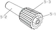
如图4所示,所述泵管接头5由接头管和具有中孔的接头旋钮5-3组成,所述接头管由密封连接的软管接头部5-1和泵管接头部5-2部组成,所述接头管穿过所述接头旋钮5-3的中孔,并且所述软管接头部5-1与所述中孔的孔壁之间具有环形空间,所述泵管接头部5-2与所述中孔的孔壁之间密封连接。所述泵管接头部5-2与所述硅胶蠕动泵管7为过盈配合连接。As shown in FIG. 4 , the pump pipe joint 5 is composed of a joint pipe and a joint knob 5-3 with a middle hole, and the joint pipe is composed of a hose joint part 5-1 and a pump pipe joint part 5-2 which are sealedly connected. The joint pipe passes through the middle hole of the joint knob 5-3, and there is an annular space between the hose joint part 5-1 and the hole wall of the middle hole, and the pump pipe joint part 5-2 is sealed with the hole wall of the middle hole. The pump tube joint part 5-2 and the silicone peristaltic pump tube 7 are connected by interference fit.
采用泵管接头5连接硅胶蠕动泵管7和第一软管4-1、以及硅胶蠕动泵管7和第二软管4-2,克服两种材质的不易粘结问题,降低了当内部压力过大时崩开的风险。同时采用软质环形锯齿卡环进行夹紧固定,进一步降低了当内部压力过大时崩开的风险,软质塑料的环形锯齿卡环可手动压紧,降低泵管压伤的可能。The pump tube joint 5 is used to connect the silicone peristaltic pump tube 7 and the first hose 4-1, as well as the silicone peristaltic pump tube 7 and the second hose 4-2, which overcomes the problem that the two materials are not easy to bond, and reduces the internal pressure when Risk of collapse when too large. At the same time, a soft annular serrated clasp is used for clamping and fixing, which further reduces the risk of collapse when the internal pressure is too large. The annular serrated clasp of soft plastic can be manually pressed to reduce the possibility of crushing the pump tube.
如图1所示,所述滴穿滤三合一组件9包括滴壶9-1、穿刺器9-2、滤网9-3和穿刺器护帽10;所述滴壶9-1的第一端通过第三软管9-4与内圆锥鲁尔接头8固定连接,所述滤网9-3设置在所述滴壶9-1第一端内部,所述穿刺器9-2安装在所述滴壶9-1的第二端上,所述穿刺器护帽10盖在所述穿刺器9-2上。滴穿滤三合一组件9与蠕动管路组件分体方式设计,可满足常规输液瓶使用,又可满足不同输液袋接口的适配。As shown in FIG. 1 , the drip filtration three-in-one assembly 9 includes a drip pot 9-1, a piercer 9-2, a filter screen 9-3 and a
具体工作原理:Specific working principle:
依次连接接头护帽1、第一个外圆锥鲁尔接头2、第一软管4-1、泵管接头5、硅胶蠕动泵管7、第二软管4-2、第二个外圆锥鲁尔接头2、内圆锥鲁尔接头8和滴穿滤三合一组件9,并通过环形锯齿卡环6对管接头5和硅胶蠕动泵管7进行加固。使用时,将硅胶蠕动泵管7放入蠕动泵中,按蠕动泵的操作说明书的要求进行使用。Connect the connector cap 1, the first external conical luer connector 2, the first hose 4-1, the pump tube connector 5, the silicone peristaltic pump tube 7, the second hose 4-2, the second external conical luer A luer connector 2, an inner conical luer connector 8 and a drip filtration three-in-one assembly 9 are used, and the tube connector 5 and the silicone peristaltic pump tube 7 are reinforced by an annular
显然,上述实施例仅仅是为清楚地说明所作的举例,而并非对实施方式的限定。对于所属领域的普通技术人员来说,在上述说明的基础上还可以做出其它不同形式的变化或变动。这里无需也无法对所有的实施方式予以穷举。而由此所引伸出的显而易见的变化或变动仍处于本专利申请权利要求的保护范围之中。Obviously, the above-mentioned embodiments are only examples for clear description, and are not intended to limit the implementation manner. For those of ordinary skill in the art, changes or modifications in other different forms can also be made on the basis of the above description. There is no need and cannot be exhaustive of all implementations here. However, the obvious changes or changes derived from this are still within the protection scope of the claims of this patent application.
Claims (8)
Translated fromChinesePriority Applications (1)
| Application Number | Priority Date | Filing Date | Title |
|---|---|---|---|
| CN201911146069.4ACN110732059A (en) | 2019-11-21 | 2019-11-21 | transfusion pipeline for pressure transfusion equipment |
Applications Claiming Priority (1)
| Application Number | Priority Date | Filing Date | Title |
|---|---|---|---|
| CN201911146069.4ACN110732059A (en) | 2019-11-21 | 2019-11-21 | transfusion pipeline for pressure transfusion equipment |
Publications (1)
| Publication Number | Publication Date |
|---|---|
| CN110732059Atrue CN110732059A (en) | 2020-01-31 |
Family
ID=69273478
Family Applications (1)
| Application Number | Title | Priority Date | Filing Date |
|---|---|---|---|
| CN201911146069.4APendingCN110732059A (en) | 2019-11-21 | 2019-11-21 | transfusion pipeline for pressure transfusion equipment |
Country Status (1)
| Country | Link |
|---|---|
| CN (1) | CN110732059A (en) |
Citations (12)
| Publication number | Priority date | Publication date | Assignee | Title |
|---|---|---|---|---|
| CN101273361A (en)* | 2005-02-01 | 2008-09-24 | 巴克斯特国际公司 | Infusion delivery system |
| CN201959397U (en)* | 2011-02-18 | 2011-09-07 | 肖刚 | Drainage catheter fixer |
| CN202740595U (en)* | 2012-08-28 | 2013-02-20 | 浙江伏尔特医疗器械有限公司 | Fixing bracket for nasal gastrointestinal cannula |
| CN203898844U (en)* | 2014-06-09 | 2014-10-29 | 山东新华安得医疗用品有限公司 | Infusion apparatus for pump |
| CN106422049A (en)* | 2016-10-31 | 2017-02-22 | 黄剑 | Bridging stent based on temporary blood circulation restoring application and processing method thereof |
| CN106880888A (en)* | 2017-03-23 | 2017-06-23 | 济世医疗器械(天津)有限公司 | A kind of purl device |
| CN108478899A (en)* | 2018-02-10 | 2018-09-04 | 陈伟权 | Can repeatedly washing pipe remaining needle |
| CN109675188A (en)* | 2019-02-25 | 2019-04-26 | 四川南格尔生物科技有限公司 | A kind of hose liquid stopping clamp structure |
| CN208809211U (en)* | 2018-01-12 | 2019-05-03 | 程卫平 | A kind of segmented blood transfusion |
| CN208959123U (en)* | 2018-03-30 | 2019-06-11 | 江苏唯德康医疗科技有限公司 | A kind of crossover sub |
| CN110389385A (en)* | 2019-08-12 | 2019-10-29 | 丰凯医疗器械(上海)有限公司 | An anti-deformation perfusion pipeline and its assembly detection method |
| CN210963360U (en)* | 2019-11-21 | 2020-07-10 | 北京哈特凯尔医疗科技有限公司 | Infusion pipeline for pressure infusion equipment |
- 2019
- 2019-11-21CNCN201911146069.4Apatent/CN110732059A/enactivePending
Patent Citations (12)
| Publication number | Priority date | Publication date | Assignee | Title |
|---|---|---|---|---|
| CN101273361A (en)* | 2005-02-01 | 2008-09-24 | 巴克斯特国际公司 | Infusion delivery system |
| CN201959397U (en)* | 2011-02-18 | 2011-09-07 | 肖刚 | Drainage catheter fixer |
| CN202740595U (en)* | 2012-08-28 | 2013-02-20 | 浙江伏尔特医疗器械有限公司 | Fixing bracket for nasal gastrointestinal cannula |
| CN203898844U (en)* | 2014-06-09 | 2014-10-29 | 山东新华安得医疗用品有限公司 | Infusion apparatus for pump |
| CN106422049A (en)* | 2016-10-31 | 2017-02-22 | 黄剑 | Bridging stent based on temporary blood circulation restoring application and processing method thereof |
| CN106880888A (en)* | 2017-03-23 | 2017-06-23 | 济世医疗器械(天津)有限公司 | A kind of purl device |
| CN208809211U (en)* | 2018-01-12 | 2019-05-03 | 程卫平 | A kind of segmented blood transfusion |
| CN108478899A (en)* | 2018-02-10 | 2018-09-04 | 陈伟权 | Can repeatedly washing pipe remaining needle |
| CN208959123U (en)* | 2018-03-30 | 2019-06-11 | 江苏唯德康医疗科技有限公司 | A kind of crossover sub |
| CN109675188A (en)* | 2019-02-25 | 2019-04-26 | 四川南格尔生物科技有限公司 | A kind of hose liquid stopping clamp structure |
| CN110389385A (en)* | 2019-08-12 | 2019-10-29 | 丰凯医疗器械(上海)有限公司 | An anti-deformation perfusion pipeline and its assembly detection method |
| CN210963360U (en)* | 2019-11-21 | 2020-07-10 | 北京哈特凯尔医疗科技有限公司 | Infusion pipeline for pressure infusion equipment |
Similar Documents
| Publication | Publication Date | Title |
|---|---|---|
| US4267834A (en) | System for flushing a medical fluid | |
| KR200492817Y1 (en) | Spike port for medical infusion solution bag | |
| CN206045076U (en) | Disposable infusion set | |
| CN110732059A (en) | transfusion pipeline for pressure transfusion equipment | |
| CN210963360U (en) | Infusion pipeline for pressure infusion equipment | |
| CN206120865U (en) | Disposable intravenous infusion needle | |
| CN217245897U (en) | A blood collection and infusion device | |
| CN208741635U (en) | Two-tube infusion apparatus | |
| CN109010990A (en) | A kind of novel infusion needleless joint | |
| CN209137582U (en) | A kind of novel infusion needleless joint | |
| CN210096535U (en) | Reusable transfusion device fixing device | |
| CN211383014U (en) | Disposable multifunctional drainage bag | |
| CN108452434B (en) | Multiple unidirectional airtight joint and pipeline device | |
| CN209679187U (en) | A valve type anti-reflux indwelling needle | |
| CN201076641Y (en) | Rapid transfusion system | |
| CN201286915Y (en) | Disposable self-closing liquid-keeping transfusion device with valve opening sac | |
| CN213374596U (en) | Vein puncture tube capable of preventing tube blockage | |
| CN221808267U (en) | Detachable plastic needle infusion set | |
| CN207708310U (en) | Wristband type universal serial infusion tube fixing apparatus | |
| CN220002580U (en) | An infusion set based on arterial drip for interventional surgery | |
| CN114452477A (en) | A blood collection and infusion device | |
| CN214105451U (en) | Infusion tube with extension tube | |
| CN215460867U (en) | Infusion apparatus capable of preventing needle tube from falling off | |
| CN211561240U (en) | Disposable drainage bag | |
| CN218922964U (en) | An eye dropper |
Legal Events
| Date | Code | Title | Description |
|---|---|---|---|
| PB01 | Publication | ||
| PB01 | Publication | ||
| SE01 | Entry into force of request for substantive examination | ||
| SE01 | Entry into force of request for substantive examination | ||
| RJ01 | Rejection of invention patent application after publication | Application publication date:20200131 | |
| RJ01 | Rejection of invention patent application after publication |