CN110730633B - Transcatheter valve, anchor, tether implant assembly - Google Patents
Transcatheter valve, anchor, tether implant assemblyDownload PDFInfo
- Publication number
- CN110730633B CN110730633BCN201880034100.2ACN201880034100ACN110730633BCN 110730633 BCN110730633 BCN 110730633BCN 201880034100 ACN201880034100 ACN 201880034100ACN 110730633 BCN110730633 BCN 110730633B
- Authority
- CN
- China
- Prior art keywords
- valve
- anchor
- tether
- medical assembly
- lumen
- Prior art date
- Legal status (The legal status is an assumption and is not a legal conclusion. Google has not performed a legal analysis and makes no representation as to the accuracy of the status listed.)
- Active
Links
Images


Classifications
- A—HUMAN NECESSITIES
- A61—MEDICAL OR VETERINARY SCIENCE; HYGIENE
- A61F—FILTERS IMPLANTABLE INTO BLOOD VESSELS; PROSTHESES; DEVICES PROVIDING PATENCY TO, OR PREVENTING COLLAPSING OF, TUBULAR STRUCTURES OF THE BODY, e.g. STENTS; ORTHOPAEDIC, NURSING OR CONTRACEPTIVE DEVICES; FOMENTATION; TREATMENT OR PROTECTION OF EYES OR EARS; BANDAGES, DRESSINGS OR ABSORBENT PADS; FIRST-AID KITS
- A61F2/00—Filters implantable into blood vessels; Prostheses, i.e. artificial substitutes or replacements for parts of the body; Appliances for connecting them with the body; Devices providing patency to, or preventing collapsing of, tubular structures of the body, e.g. stents
- A61F2/02—Prostheses implantable into the body
- A61F2/24—Heart valves ; Vascular valves, e.g. venous valves; Heart implants, e.g. passive devices for improving the function of the native valve or the heart muscle; Transmyocardial revascularisation [TMR] devices; Valves implantable in the body
- A61F2/2412—Heart valves ; Vascular valves, e.g. venous valves; Heart implants, e.g. passive devices for improving the function of the native valve or the heart muscle; Transmyocardial revascularisation [TMR] devices; Valves implantable in the body with soft flexible valve members, e.g. tissue valves shaped like natural valves
- A61F2/2418—Scaffolds therefor, e.g. support stents
- A—HUMAN NECESSITIES
- A61—MEDICAL OR VETERINARY SCIENCE; HYGIENE
- A61F—FILTERS IMPLANTABLE INTO BLOOD VESSELS; PROSTHESES; DEVICES PROVIDING PATENCY TO, OR PREVENTING COLLAPSING OF, TUBULAR STRUCTURES OF THE BODY, e.g. STENTS; ORTHOPAEDIC, NURSING OR CONTRACEPTIVE DEVICES; FOMENTATION; TREATMENT OR PROTECTION OF EYES OR EARS; BANDAGES, DRESSINGS OR ABSORBENT PADS; FIRST-AID KITS
- A61F2/00—Filters implantable into blood vessels; Prostheses, i.e. artificial substitutes or replacements for parts of the body; Appliances for connecting them with the body; Devices providing patency to, or preventing collapsing of, tubular structures of the body, e.g. stents
- A61F2/02—Prostheses implantable into the body
- A61F2/24—Heart valves ; Vascular valves, e.g. venous valves; Heart implants, e.g. passive devices for improving the function of the native valve or the heart muscle; Transmyocardial revascularisation [TMR] devices; Valves implantable in the body
- A61F2/2427—Devices for manipulating or deploying heart valves during implantation
- A61F2/2436—Deployment by retracting a sheath
- A—HUMAN NECESSITIES
- A61—MEDICAL OR VETERINARY SCIENCE; HYGIENE
- A61F—FILTERS IMPLANTABLE INTO BLOOD VESSELS; PROSTHESES; DEVICES PROVIDING PATENCY TO, OR PREVENTING COLLAPSING OF, TUBULAR STRUCTURES OF THE BODY, e.g. STENTS; ORTHOPAEDIC, NURSING OR CONTRACEPTIVE DEVICES; FOMENTATION; TREATMENT OR PROTECTION OF EYES OR EARS; BANDAGES, DRESSINGS OR ABSORBENT PADS; FIRST-AID KITS
- A61F2/00—Filters implantable into blood vessels; Prostheses, i.e. artificial substitutes or replacements for parts of the body; Appliances for connecting them with the body; Devices providing patency to, or preventing collapsing of, tubular structures of the body, e.g. stents
- A61F2/02—Prostheses implantable into the body
- A61F2/24—Heart valves ; Vascular valves, e.g. venous valves; Heart implants, e.g. passive devices for improving the function of the native valve or the heart muscle; Transmyocardial revascularisation [TMR] devices; Valves implantable in the body
- A61F2/2442—Annuloplasty rings or inserts for correcting the valve shape; Implants for improving the function of a native heart valve
- A61F2/2454—Means for preventing inversion of the valve leaflets, e.g. chordae tendineae prostheses
- A61F2/2457—Chordae tendineae prostheses
- A—HUMAN NECESSITIES
- A61—MEDICAL OR VETERINARY SCIENCE; HYGIENE
- A61F—FILTERS IMPLANTABLE INTO BLOOD VESSELS; PROSTHESES; DEVICES PROVIDING PATENCY TO, OR PREVENTING COLLAPSING OF, TUBULAR STRUCTURES OF THE BODY, e.g. STENTS; ORTHOPAEDIC, NURSING OR CONTRACEPTIVE DEVICES; FOMENTATION; TREATMENT OR PROTECTION OF EYES OR EARS; BANDAGES, DRESSINGS OR ABSORBENT PADS; FIRST-AID KITS
- A61F2/00—Filters implantable into blood vessels; Prostheses, i.e. artificial substitutes or replacements for parts of the body; Appliances for connecting them with the body; Devices providing patency to, or preventing collapsing of, tubular structures of the body, e.g. stents
- A61F2/02—Prostheses implantable into the body
- A61F2/24—Heart valves ; Vascular valves, e.g. venous valves; Heart implants, e.g. passive devices for improving the function of the native valve or the heart muscle; Transmyocardial revascularisation [TMR] devices; Valves implantable in the body
- A61F2/2442—Annuloplasty rings or inserts for correcting the valve shape; Implants for improving the function of a native heart valve
- A61F2/246—Devices for obstructing a leak through a native valve in a closed condition
- A—HUMAN NECESSITIES
- A61—MEDICAL OR VETERINARY SCIENCE; HYGIENE
- A61F—FILTERS IMPLANTABLE INTO BLOOD VESSELS; PROSTHESES; DEVICES PROVIDING PATENCY TO, OR PREVENTING COLLAPSING OF, TUBULAR STRUCTURES OF THE BODY, e.g. STENTS; ORTHOPAEDIC, NURSING OR CONTRACEPTIVE DEVICES; FOMENTATION; TREATMENT OR PROTECTION OF EYES OR EARS; BANDAGES, DRESSINGS OR ABSORBENT PADS; FIRST-AID KITS
- A61F2/00—Filters implantable into blood vessels; Prostheses, i.e. artificial substitutes or replacements for parts of the body; Appliances for connecting them with the body; Devices providing patency to, or preventing collapsing of, tubular structures of the body, e.g. stents
- A61F2/02—Prostheses implantable into the body
- A61F2/24—Heart valves ; Vascular valves, e.g. venous valves; Heart implants, e.g. passive devices for improving the function of the native valve or the heart muscle; Transmyocardial revascularisation [TMR] devices; Valves implantable in the body
- A61F2/2442—Annuloplasty rings or inserts for correcting the valve shape; Implants for improving the function of a native heart valve
- A61F2/2466—Delivery devices therefor
- A—HUMAN NECESSITIES
- A61—MEDICAL OR VETERINARY SCIENCE; HYGIENE
- A61F—FILTERS IMPLANTABLE INTO BLOOD VESSELS; PROSTHESES; DEVICES PROVIDING PATENCY TO, OR PREVENTING COLLAPSING OF, TUBULAR STRUCTURES OF THE BODY, e.g. STENTS; ORTHOPAEDIC, NURSING OR CONTRACEPTIVE DEVICES; FOMENTATION; TREATMENT OR PROTECTION OF EYES OR EARS; BANDAGES, DRESSINGS OR ABSORBENT PADS; FIRST-AID KITS
- A61F2/00—Filters implantable into blood vessels; Prostheses, i.e. artificial substitutes or replacements for parts of the body; Appliances for connecting them with the body; Devices providing patency to, or preventing collapsing of, tubular structures of the body, e.g. stents
- A61F2/02—Prostheses implantable into the body
- A61F2/24—Heart valves ; Vascular valves, e.g. venous valves; Heart implants, e.g. passive devices for improving the function of the native valve or the heart muscle; Transmyocardial revascularisation [TMR] devices; Valves implantable in the body
- A61F2/2412—Heart valves ; Vascular valves, e.g. venous valves; Heart implants, e.g. passive devices for improving the function of the native valve or the heart muscle; Transmyocardial revascularisation [TMR] devices; Valves implantable in the body with soft flexible valve members, e.g. tissue valves shaped like natural valves
- A—HUMAN NECESSITIES
- A61—MEDICAL OR VETERINARY SCIENCE; HYGIENE
- A61F—FILTERS IMPLANTABLE INTO BLOOD VESSELS; PROSTHESES; DEVICES PROVIDING PATENCY TO, OR PREVENTING COLLAPSING OF, TUBULAR STRUCTURES OF THE BODY, e.g. STENTS; ORTHOPAEDIC, NURSING OR CONTRACEPTIVE DEVICES; FOMENTATION; TREATMENT OR PROTECTION OF EYES OR EARS; BANDAGES, DRESSINGS OR ABSORBENT PADS; FIRST-AID KITS
- A61F2210/00—Particular material properties of prostheses classified in groups A61F2/00 - A61F2/26 or A61F2/82 or A61F9/00 or A61F11/00 or subgroups thereof
- A61F2210/0014—Particular material properties of prostheses classified in groups A61F2/00 - A61F2/26 or A61F2/82 or A61F9/00 or A61F11/00 or subgroups thereof using shape memory or superelastic materials, e.g. nitinol
- A—HUMAN NECESSITIES
- A61—MEDICAL OR VETERINARY SCIENCE; HYGIENE
- A61F—FILTERS IMPLANTABLE INTO BLOOD VESSELS; PROSTHESES; DEVICES PROVIDING PATENCY TO, OR PREVENTING COLLAPSING OF, TUBULAR STRUCTURES OF THE BODY, e.g. STENTS; ORTHOPAEDIC, NURSING OR CONTRACEPTIVE DEVICES; FOMENTATION; TREATMENT OR PROTECTION OF EYES OR EARS; BANDAGES, DRESSINGS OR ABSORBENT PADS; FIRST-AID KITS
- A61F2210/00—Particular material properties of prostheses classified in groups A61F2/00 - A61F2/26 or A61F2/82 or A61F9/00 or A61F11/00 or subgroups thereof
- A61F2210/0061—Particular material properties of prostheses classified in groups A61F2/00 - A61F2/26 or A61F2/82 or A61F9/00 or A61F11/00 or subgroups thereof swellable
- A—HUMAN NECESSITIES
- A61—MEDICAL OR VETERINARY SCIENCE; HYGIENE
- A61F—FILTERS IMPLANTABLE INTO BLOOD VESSELS; PROSTHESES; DEVICES PROVIDING PATENCY TO, OR PREVENTING COLLAPSING OF, TUBULAR STRUCTURES OF THE BODY, e.g. STENTS; ORTHOPAEDIC, NURSING OR CONTRACEPTIVE DEVICES; FOMENTATION; TREATMENT OR PROTECTION OF EYES OR EARS; BANDAGES, DRESSINGS OR ABSORBENT PADS; FIRST-AID KITS
- A61F2220/00—Fixations or connections for prostheses classified in groups A61F2/00 - A61F2/26 or A61F2/82 or A61F9/00 or A61F11/00 or subgroups thereof
- A61F2220/0008—Fixation appliances for connecting prostheses to the body
- A61F2220/0016—Fixation appliances for connecting prostheses to the body with sharp anchoring protrusions, e.g. barbs, pins, spikes
- A—HUMAN NECESSITIES
- A61—MEDICAL OR VETERINARY SCIENCE; HYGIENE
- A61F—FILTERS IMPLANTABLE INTO BLOOD VESSELS; PROSTHESES; DEVICES PROVIDING PATENCY TO, OR PREVENTING COLLAPSING OF, TUBULAR STRUCTURES OF THE BODY, e.g. STENTS; ORTHOPAEDIC, NURSING OR CONTRACEPTIVE DEVICES; FOMENTATION; TREATMENT OR PROTECTION OF EYES OR EARS; BANDAGES, DRESSINGS OR ABSORBENT PADS; FIRST-AID KITS
- A61F2220/00—Fixations or connections for prostheses classified in groups A61F2/00 - A61F2/26 or A61F2/82 or A61F9/00 or A61F11/00 or subgroups thereof
- A61F2220/0025—Connections or couplings between prosthetic parts, e.g. between modular parts; Connecting elements
- A61F2220/0075—Connections or couplings between prosthetic parts, e.g. between modular parts; Connecting elements sutured, ligatured or stitched, retained or tied with a rope, string, thread, wire or cable
- A—HUMAN NECESSITIES
- A61—MEDICAL OR VETERINARY SCIENCE; HYGIENE
- A61F—FILTERS IMPLANTABLE INTO BLOOD VESSELS; PROSTHESES; DEVICES PROVIDING PATENCY TO, OR PREVENTING COLLAPSING OF, TUBULAR STRUCTURES OF THE BODY, e.g. STENTS; ORTHOPAEDIC, NURSING OR CONTRACEPTIVE DEVICES; FOMENTATION; TREATMENT OR PROTECTION OF EYES OR EARS; BANDAGES, DRESSINGS OR ABSORBENT PADS; FIRST-AID KITS
- A61F2250/00—Special features of prostheses classified in groups A61F2/00 - A61F2/26 or A61F2/82 or A61F9/00 or A61F11/00 or subgroups thereof
- A61F2250/0004—Special features of prostheses classified in groups A61F2/00 - A61F2/26 or A61F2/82 or A61F9/00 or A61F11/00 or subgroups thereof adjustable
- A—HUMAN NECESSITIES
- A61—MEDICAL OR VETERINARY SCIENCE; HYGIENE
- A61F—FILTERS IMPLANTABLE INTO BLOOD VESSELS; PROSTHESES; DEVICES PROVIDING PATENCY TO, OR PREVENTING COLLAPSING OF, TUBULAR STRUCTURES OF THE BODY, e.g. STENTS; ORTHOPAEDIC, NURSING OR CONTRACEPTIVE DEVICES; FOMENTATION; TREATMENT OR PROTECTION OF EYES OR EARS; BANDAGES, DRESSINGS OR ABSORBENT PADS; FIRST-AID KITS
- A61F2250/00—Special features of prostheses classified in groups A61F2/00 - A61F2/26 or A61F2/82 or A61F9/00 or A61F11/00 or subgroups thereof
- A61F2250/0058—Additional features; Implant or prostheses properties not otherwise provided for
- A61F2250/0069—Sealing means
Landscapes
- Health & Medical Sciences (AREA)
- Cardiology (AREA)
- Engineering & Computer Science (AREA)
- Biomedical Technology (AREA)
- Life Sciences & Earth Sciences (AREA)
- Transplantation (AREA)
- Heart & Thoracic Surgery (AREA)
- Vascular Medicine (AREA)
- Oral & Maxillofacial Surgery (AREA)
- Animal Behavior & Ethology (AREA)
- General Health & Medical Sciences (AREA)
- Public Health (AREA)
- Veterinary Medicine (AREA)
- Prostheses (AREA)
- Surgical Instruments (AREA)
- Media Introduction/Drainage Providing Device (AREA)
- Structures Of Non-Positive Displacement Pumps (AREA)
Abstract
Translated fromChinese
Description
Translated fromChinese技术领域technical field
本发明总体上涉及一种用于将瓣膜微创地植入心脏中的医疗组件,一种用于置换原生心脏瓣膜的新颖的瓣膜,以及一种用于定位和约束瓣膜的锚固系统。本发明还涉及医疗组件的部件和瓣膜的植入方法。更具体地,本发明涉及新颖的经导管的瓣膜、经导管的瓣膜裙部、系绳和锚固件、锚固件递送系统以及瓣膜递送装置,以及与这种组件相关的、用于血管内植入瓣膜以跨三尖瓣、以置换原生三尖瓣的功能的方法。The present invention generally relates to a medical assembly for minimally invasive implantation of a valve in the heart, a novel valve for replacing a native heart valve, and an anchoring system for positioning and constraining the valve. The invention also relates to components of medical assemblies and methods of implanting valves. More particularly, the present invention relates to novel transcatheter valves, transcatheter valve skirts, tethers and anchors, anchor delivery systems, and valve delivery devices, and related such assemblies for endovascular implantation A valve that spans the tricuspid valve to replace the function of the native tricuspid valve.
背景技术Background technique
经导管(transcatheter)的瓣膜已被证明可安全有效地置换原生心脏瓣膜。尽管已经对置换主动脉瓣、二尖瓣和肺动脉瓣进行了广泛的试验,但是由于假体必须锚固在复杂而脆弱的解剖结构上,因此三尖瓣置换的经验较少。而且鉴于各心脏瓣膜环或其他各体腔的形状和尺寸上的巨大异质性,在各心脏瓣膜或其他各体腔的原位(in situ)位置中锚定仍然是具有挑战性的。在这方面,三尖瓣反流的治疗仍然是最具挑战性的,并且经导管的治疗的开发较少。Transcatheter valves have been shown to be safe and effective replacements for native heart valves. Although replacement of the aortic, mitral, and pulmonary valves has been extensively tested, there is less experience with tricuspid valve replacement because of the complex and delicate anatomy into which the prosthesis must be anchored. Furthermore, anchoring in the in situ position of individual heart valves or other body lumens remains challenging given the enormous heterogeneity in the shape and size of each heart valve annulus or other body lumen. In this regard, treatment of tricuspid regurgitation remains the most challenging, and transcatheter therapy is less developed.
尖瓣瓣膜疾病,主要是三尖瓣反流( tricuspid regurgitation,TR),是由瓣膜的原发性退化(例如心内膜炎、风湿性疾病、类癌、先天性疾病、药物、心内导线穿孔或其他原因)所引起的,或更常见地由继发于右心房和/或右心室扩张的三尖瓣环扩张引起。TR导致右心房容量超负荷,这使得上腔静脉( superior vena cava,SVC)和下腔静脉( inferiorvena cava,IVC) 充血( congest)。SVC充血导致上身多血症( plethora of the upperbody),IVC充血导致肝/肾淤血,导致充血性心衰竭的体征和症状,即外周性水肿、腹水、劳力性呼吸困难和其他症状。此外,TR引起的持续右心容量超负荷会导致进行性右心室扩张和衰竭(progressive right ventricular dilation and failure),从而增加死亡率。由于患有TR的患者通常具有较高的手术风险,因此开发微创经导管的治疗TR的方法就很重要。Apical valve disease, primarily tricuspid regurgitation (TR), is caused by primary degeneration of the valve (eg, endocarditis, rheumatic disease, carcinoid, congenital disease, drug, intracardiac lead perforation or other cause) or, more commonly, dilation of the tricuspid annulus secondary to dilation of the right atrium and/or right ventricle. TR causes volume overload in the right atrium, which congests the superior vena cava (SVC) and inferior vena cava (IVC). SVC congestion leads to plethora of the upper body and IVC congestion leads to hepatic/renal congestion leading to signs and symptoms of congestive heart failure, ie peripheral edema, ascites, exertional dyspnea, and other symptoms. In addition, persistent right ventricular volume overload due to TR leads to progressive right ventricular dilation and failure, which increases mortality. Since patients with TR often have high surgical risk, it is important to develop minimally invasive transcatheter methods for treating TR.
在2005年,Boudjemline等人开发了一种新型的支架瓣膜,并将其放置在八只羊的三尖瓣环中。一只动物的瓣膜被卡(trap)在三尖瓣腱索中,而另一只动物的瓣膜有明显的瓣周反流(paravalvular regurgitation),引起了对这种方法的担忧。瓣膜没有进一步发展。在2008年,Bai等人试验了类似类型的支架瓣膜,将其植入了十只羊的三尖瓣环中。手术过程中有两只动物死亡。尽管这种瓣膜在存活的绵羊中持续作用长达六个月,但没有对这种瓣膜继续进一步的开发。In 2005, Boudjemline et al. developed a novel stent-valve and placed it in the tricuspid annulus of eight sheep. One animal had a valve trapped in the tricuspid chordae, while another animal had a valve with marked paravalvular regurgitation, raising concerns about this approach. The valve did not develop further. In 2008, Bai et al. experimented with a similar type of stented valve, implanting it in the tricuspid annulus of ten sheep. Two animals died during the procedure. Although the valve lasted for up to six months in surviving sheep, no further development of the valve continued.
由于将瓣膜锚固在三尖瓣环中的这些挑战,Lauten等人在2010年设计并将支架瓣膜植入在严重TR的绵羊模型的IVC和SVC中,从而使三尖瓣反流量通过腔静脉到达器官的传递最小化。他们表现出IVC压力降低和心输出量增加。Because of these challenges in anchoring the valve in the tricuspid annulus, Lauten et al. in 2010 designed and implanted stented valves in the IVC and SVC in a sheep model of severe TR, allowing tricuspid regurgitant flow to reach via the vena cava Organ delivery is minimized. They showed reduced IVC pressure and increased cardiac output.
Lauten和Laule分别在2011年和2013年在患有严重TR的患者的腔静脉中植入了类似的定制( custom-made)的自膨胀式支架,并且这两个患者的腔静脉压力都持续降低并且在12个月时得到了临床改善。Lauten and Laule implanted similar custom-made self-expanding stents in the vena cava of patients with severe TR in 2011 and 2013, respectively, and both patients experienced sustained reductions in vena cava pressure And there was clinical improvement at 12 months.
美国专利(专利号7,530,995)描述了一种类似于上述方法的装置,所述装置通过将支架化的组织瓣膜(通过至少一细长的连接构件而被固定到IVC中的第二个支架化的组织瓣膜)放置在SVC中来降低TR的压力作用。美国专利申请(公开号2012/0136430A1)详细描述了一种类似的装置,所述装置由通过桥接件连接的两个腔静脉支架所组成,两个圆锥形瓣膜可沿桥接件移动以调节瓣膜之间的距离。US Patent (Patent No. 7,530,995) describes a device similar to the method described above by securing a stented tissue valve (via at least one elongated connecting member) to a second stented tissue valve in the IVC. Tissue valves) are placed in the SVC to reduce the pressure effect of the TR. U.S. Patent Application Publication No. 2012/0136430A1 describes a similar device in detail, consisting of two vena cava stents connected by a bridge along which two conical valves move to adjust the distance between the valves. distance between.
Laule等人通过在三个患者的腔静脉中使用市售的经导管的瓣膜(Sapien XT(Edwards LifeSciences,尔湾,加利福尼亚),其使用自膨胀式支架作为着陆区(landingzones))进一步简化瓣膜在腔静脉内的植入。Laule et al further simplified valve placement by using a commercially available transcatheter valve (Sapien XT (Edwards LifeSciences, Irvine, CA), which uses self-expanding stents as landing zones) in the vena cava of three patients. Implantation in the vena cava.
在[0006-0009]段中详述的方法受到一些限制。Lauten和Laule的技术以及[0008]中描述的装置需要为每个患者进行定制,导致生物瓣膜尺寸范围广泛。固有地,尺寸范围广泛导致不确定的耐用性和功能,并且由于需要个性化定制而限制了广泛的应用。Laule使用市售的经导管的瓣膜——Sapien瓣膜(在数千的患者中具有已知的性能和耐用性)的技术部分解决了这一问题,但受到就位困难和瓣周反流(由于植入在大于最大的Sapien瓣膜-29毫米的SVC或IVC中,通常发生在TR患者中)的限制。同样地,其他目前可用的瓣膜不能在直径大于30-31毫米的SVC/IVC中工作。The methods detailed in paragraphs [0006-0009] are subject to some limitations. The technique of Lauten and Laule and the devices described in [0008] need to be customized for each patient, resulting in a wide range of bioprosthetic valve sizes. Inherently, the wide range of sizes leads to uncertain durability and functionality, and limits broad applications due to the need for individual customization. Laule partially solved this problem using the technology of a commercially available transcatheter valve, the Sapien valve (of known performance and durability in thousands of patients), but suffers from difficulty in positioning and paravalvular regurgitation (due to Implantation in SVC or IVC larger than the largest Sapien valve -29 mm, usually occurs in TR patients). Likewise, other currently available valves do not work in SVC/IVC diameters larger than 30-31 mm.
为了解决这个问题,Lauten及其同事开发了SVC和IVC自膨胀式假体(Trie 瓣膜(德国Vertriebs GmbH)),它解决了第[0007]段中概述的一些尺寸和定制问题。To address this issue, Lauten and colleagues developed SVC and IVC self-expanding prostheses (Trie valves (Vertriebs GmbH, Germany)), which address some of the sizing and customization issues outlined in paragraph [0007].
尽管如此,在[0006-0009和0011]中概述的腔静脉瓣膜方案受到相同的限制;具体地,IVC和/或SVC支架瓣膜不能完全恢复三尖瓣的功能,因为它们没有置于解剖学上正确的位置——跨三尖瓣环。因此它们可缓解症状,但不能从根本上解决由TR引起的右心室(RV)容量超负荷。为了解决容量超负荷的问题,需要跨原生三尖瓣的瓣膜在瓣环内锚固。考虑到三尖瓣环的脆弱和复杂的抛物面瓣环解剖结构,以及在连接到瓣环的心房和心室中大且扩口状的锚固区域,上述技术不适用于经导管的瓣膜的瓣环内锚固。Nonetheless, the vena cava protocol outlined in [0006-0009 and 0011] suffers from the same limitations; specifically, IVC and/or SVC stented valves cannot fully restore tricuspid valve function because they are not placed anatomically Correct position - across the tricuspid annulus. They therefore relieve symptoms but do not address the underlying right ventricular (RV) volume overload caused by TR. To address volume overload, intraannular anchoring of the valve across the native tricuspid valve is required. Given the fragility and complex parabolic annulus anatomy of the tricuspid annulus, as well as the large and flared anchoring regions in the atria and ventricles connected to the annulus, the above technique is not suitable for intraannular transcatheter valves. anchor.
尽管研究者已经开发出对接系统(docking system)以辅助经导管的瓣膜的瓣环内锚固,但是由于多种原因,这些技术不太可能用于三尖瓣。例如,Barbanti及其同事已经试验了Helio经导管的主动脉对接( Edwards LifeSciences,尔湾,加利福尼亚)(一种覆盖有膨胀聚四氟乙烯(ePTFE)的自膨胀式支架)作为跨一严重反流的主动脉瓣的平台(platform),以锚固Sapien经导管的主动脉瓣。尽管在此位置有效,但此平台不会保持锚固在一三尖瓣环中。与主动脉瓣环不同,三尖瓣环具有复杂的抛物面形状,易于扩张且缺钙,这可能会阻止Helio对接(一种简单的管状结构)保持原位。Although investigators have developed docking systems to assist in the intraannular anchoring of transcatheter valves, these techniques are unlikely to be used for tricuspid valves for several reasons. For example, Barbanti and colleagues have tested Helio transcatheter aortic docking (Edwards LifeSciences, Irvine, Calif.), a self-expanding stent covered with expanded polytetrafluoroethylene (ePTFE), as an alternative to patients with severe regurgitation. The aortic valve platform (platform) to anchor the Sapien transcatheter aortic valve. Although effective in this position, the platform will not remain anchored in a tricuspid annulus. Unlike the aortic annulus, the tricuspid annulus has a complex parabolic shape that is prone to dilation and lacks calcium, which may prevent the Helio docking, a simple tubular structure, from staying in place.
Buchbinder及其同事开发了一种对接系统,以将经导管的主动脉瓣锚固在二尖瓣位置。他们描述了一种对接系统,所述对接系统包括用于心房内和/或心室内稳定的一或两个自膨胀式或球囊膨胀式环(由刚性和半刚性材料组成)、以及连接所述环并将经导管的瓣膜锁定到位的多个桥接构件。二尖瓣环(侧面为肥厚的纤维三角,并与肥厚的左心室心肌连接)具有外部支撑以容纳可膨胀的刚性和半刚性材料。 Buchbinder and colleagues developed a docking system to anchor the transcatheter aortic valve in the mitral position. They describe a docking system consisting of one or two self-expanding or balloon-expandable rings (composed of rigid and semi-rigid materials) for intraatrial and/or intraventricular A plurality of bridging members that describe the ring and lock the transcatheter valve in place. The mitral annulus (lateralized by the hypertrophic fibrous triangle and attached to the hypertrophic left ventricular myocardium) has external support to accommodate expandable rigid and semirigid materials.
相反,三尖瓣环的大约四分之三具有最小的外部支撑,并且连接到薄壁的且可扩张的右心房和右心室。考虑到所述瓣环的脆弱性,任一金属对接系统(即使使用诸如镍钛诺这样的具有顺应性的金属)在三尖瓣环周围的侵蚀风险比在其他任意瓣膜环的侵蚀风险都更高。而且由于任何三尖瓣环都可能在数周的时间内扩张,因此任何刚性或半刚性的锚固装置都可能随时间推移而发生错位。In contrast, approximately three-quarters of the tricuspid annulus has minimal external support and is connected to the thin-walled and expandable right atrium and right ventricle. Given the fragility of the annulus, any metal docking system (even with a compliant metal such as Nitinol) is at a greater risk of erosion around the tricuspid annulus than any other annulus. high. And because any tricuspid annulus may dilate over a period of weeks, any rigid or semi-rigid anchoring device may become misaligned over time.
为了解决三尖瓣环扩张,已经进行了几种经导管的方法以减小瓣环尺寸,从而允许更好的三尖瓣对合并降低TR。在SCOUT I试验中,研究人员描述使用Mitralign系统(Mitralign Inc.,美国马萨诸塞州图克斯伯里)通过经颈静脉的方法将脱脂棉缝线(pledgeted sutures)放入三尖瓣环中,从而缩小瓣环尺寸。类似地,TriCinch装置(4Tech,Galway,Ireland)通过瓣环中的螺钉以减小瓣环尺寸,所述螺钉张紧在IVC中的支架上。Cardioband装置(Valtech,Edwards lifecience,尔湾,加利福尼亚)(模仿外科环,是一种半完整的瓣环成形术环)可以被微创地递送和固定到三尖瓣环上。同样,Millipede装置(Boston Scientific,马萨诸塞州马尔伯勒)模仿了一个完整的外科瓣环成形术环,并且可以被微创地递送。To address tricuspid annular dilatation, several transcatheter approaches have been performed to reduce the annulus size, thereby allowing better tricuspid pairing and reducing TR. In the SCOUT I trial, investigators describe the use of the Mitralalign System (Mitralalign Inc., Tewkesbury, MA, USA) to place pledget sutures into the tricuspid annulus via a transjugular approach to narrow the size of the tricuspid annulus. Annulus size. Similarly, the TriCinch device (4Tech, Galway, Ireland) was used to reduce the size of the annulus by means of screws in the annulus that are tensioned over a stent in the IVC. A Cardioband device (Valtech, Edwards lifescience, Irvine, CA) (mimicking a surgical ring, a semi-intact annuloplasty ring) can be delivered and secured to the tricuspid annulus minimally invasively. Likewise, the Millipede device (Boston Scientific, Marlborough, MA) mimics a full surgical annuloplasty ring and can be delivered minimally invasively.
然而,这些方法具有限制。Mitralign系统的学习曲线陡峭,通常会留下中度至严重的残余TR,不能修复瓣叶异常,并且在存在心内导线的情况下效果较差。而且尽管瓣环减小,但任何进一步的RV重塑和瓣叶移位(leaflet tethering)都将导致复发性TR。相同的限制适用于TriCinch装置,TriCinch装置还具有在IVC中需要支架的缺点。尽管Cardioband装置可提供更完整的瓣环减小,但它也会留下中度至严重的TR,并且在存在瓣叶异常或心内导线时效果不佳。最后,具有一完整瓣环的Millipede装置最大程度地减小环,但同样不能解决瓣叶异常或心内导线的问题。However, these methods have limitations. The Mitralalign system has a steep learning curve, typically leaves moderate to severe residual TR, fails to repair leaflet abnormalities, and is less effective in the presence of an intracardiac lead. And despite annular reduction, any further RV remodeling and leaflet tethering will lead to recurrent TR. The same limitations apply to the TriCinch device, which also has the disadvantage of requiring a stent in the IVC. Although the Cardioband device provides more complete annulus reduction, it also leaves moderate to severe TR and is less effective in the presence of leaflet abnormalities or intracardiac leads. Finally, the Millipede device with a full annulus minimizes the annulus, but again does not address leaflet abnormalities or intracardiac leads.
其他经导管方法通过装置与瓣叶的直接相互作用来促进瓣叶接合而解决TR。Parada-Campello及其同事描述了他们使用FormaRepair系统 (Edwards LifeSciences,尔湾,加利福尼亚)的初步经验。该装置由一泡沫填充的聚合物球囊所组成,所述球囊位于RV锚固件的上方,使三尖瓣瓣叶接合间隔物(spacer)(假设瓣叶具有功能能力(functionalcompetency)),从而降低TR。另一装置是MitraClip( Abbott Vascular,Abbott Park,Illinois,USA),用于将瓣叶折叠(plicate)在一起。Other transcatheter approaches address TR through direct device-leaflet interaction to facilitate leaflet coaptation. Parada-Campello and colleagues describe their initial experience with the FormaRepair system (Edwards LifeSciences, Irvine, CA). The device consists of a foam-filled polymer balloon positioned over the RV anchor to engage the tricuspid leaflets with the spacer (assuming functional competence of the leaflets), thereby Lower TR. Another device is the MitraClip (Abbott Vascular, Abbott Park, Illinois, USA), which is used to replicate the leaflets together.
然而两个装置都受到明显的限制。Forma Repair系统具有一固定尺寸的球囊,植入后任何进一步的瓣环扩张和/或瓣叶移位都会导致TR复发。此外,最初的人类经验表明:主要的不良事件(包括锚固件移位、心包填塞和紧急心脏手术)发生率较高。从技术上讲,使用MitraClip系统进行三尖瓣夹持(clipping)具有不确定的再现性,且中度至重度的残余TR很常见。与瓣环成形术一样,在存在明显的瓣叶异常或起搏器导线(pacemaker leads)的情况下,Forma Repair系统和MitraClip无法有效治疗TR。Both devices suffer from significant limitations, however. The Forma Repair system has a fixed-size balloon, and any further annulus dilatation and/or leaflet displacement after implantation will result in recurrence of TR. In addition, initial human experience has shown a high rate of major adverse events, including anchor displacement, cardiac tamponade, and emergency cardiac surgery. Technically, tricuspid valve clipping with the MitraClip system has uncertain reproducibility, and moderate to severe residual TR is common. As with annuloplasty, the Forma Repair System and MitraClip are not effective in treating TR in the presence of significant leaflet abnormalities or pacemaker leads.
在这方面,考虑到脆弱的三尖瓣和右心室问题,如果经导管的瓣膜可以在不需要瓣叶或瓣环固定的情况下进行锚固,则可以解决上述问题,同时使损伤的风险最小化。In this regard, given the fragile tricuspid valve and right ventricle, if a transcatheter valve could be anchored without leaflet or annulus fixation, the above problems could be resolved while minimizing the risk of injury .
美国专利申请(公开号US2013/0172978A1)描述一种置于二尖瓣位置的瓣膜,其具有心房裙部、瓣环内瓣膜和心室系绳(ventricular tether);所述系统不需要瓣环或瓣叶固定,这是其他没有系绳的经导管的瓣膜所需的。然而,所述瓣膜需要经心尖进入心室,这是一种对右心室非常高风险的方法。同样,系绳固定在瓣膜的末端。因此,通过拉动系绳经过经心尖的切口并用心外膜锚固件将其固定(这需要进行开胸手术并到达心尖),则可以调节瓣膜位置。US Patent Application (Publication No. US2013/0172978A1) describes a valve placed in the mitral position with an atrial skirt, an intraannular valve, and a ventricular tether; the system does not require an annulus or valve Leaf fixation is required for other non-tethered transcatheter valves. However, the valve requires transapical access to the ventricle, a very risky approach to the right ventricle. Likewise, a tether is secured to the end of the valve. Thus, valve position can be adjusted by pulling the tether through the transapical incision and securing it with epicardial anchors (which requires a thoracotomy and access to the apex).
相反,Lux瓣膜(Ningbo Jenscare Biotechnology Co.,LTD,宁波,中国)由固定在瓣膜末端的三角板(triangular paddle)固定,所述三角板锚固至室间隔。尽管Lux瓣膜显示出在山羊中稳定的锚固,但这些动物的心脏较小呈非球形(三尖瓣环的平均大小为~2.5厘米,而人为≥4厘米)。鉴于这些患者右心室的基础/纵向重构(basal/longitudinalremodeling)存在巨大的异质性,目前尚不清楚固定的心室锚固件在重度TR的人类患者中如何发挥作用。另外,许多TR患者患有右心室功能障碍(right ventriculardysfunction),并且固定在右心室心肌的系绳(通过物理约束或疤痕诱导(physicalrestraint or induction of scarring))可能进一步损害右心室功能。In contrast, the Lux valve (Ningbo Jenscare Biotechnology Co., LTD, Ningbo, China) is secured by a triangular paddle fixed at the end of the valve, which is anchored to the interventricular septum. Although the Lux valve showed stable anchoring in goats, the hearts of these animals were small and non-spherical (mean tricuspid annulus size ~2.5 cm vs. ≥4 cm in humans). Given the enormous heterogeneity in basal/longitudinal remodeling of the RV in these patients, it remains unclear how fixed ventricular anchors might work in human patients with severe TR. In addition, many TR patients suffer from right ventricular dysfunction, and tethers anchored to the right ventricular myocardium (by physical restraint or induction of scarring) may further impair right ventricular function.
NaviGate 瓣膜(NaviGate Cardiac Structures,Inc.,森林湖,加利福尼亚)不需要系绳,因为它使用瓣叶和瓣环固定,以直接锚固到原生三尖瓣上。尽管最初的人类经验还未显示右心房或心室损伤,但其在瓣叶和瓣环上的锚固机制阻止其在手术过程中的重新定位或取回(这是重要的安全特性)。此外,Navigate的瓣环锚固机制需要大的瓣膜,因此需要非常大的递送系统,这限制真正的经皮递送以选择患者。Navigate的大尺寸也使其在结构破坏(structural deterioration)的情况下无法用作市售的经导管的瓣膜的对接系统。最后,考虑到它需要完全膨胀以抵靠瓣环,不太可能在先前的使用MitraClip的三尖瓣瓣叶夹持的情况下植入所述瓣膜,并且所述瓣膜很可能会损坏任何已经存在的穿过三尖瓣的心内导线。 The NaviGate valve (NaviGate Cardiac Structures, Inc., Lake Forest, CA) does not require a tether because it uses leaflet and annulus fixation for direct anchoring to the native tricuspid valve. Although initial human experience has not shown right atrial or ventricular damage, its anchoring mechanism on the leaflets and annulus prevents its repositioning or retrieval during surgery (an important safety feature). Additionally, Navigate's annulus anchoring mechanism requires a large valve and thus a very large delivery system, which limits true percutaneous delivery to select patients. The large size of Navigate also precludes its use as a docking system for commercially available transcatheter valves in case of structural deterioration. Finally, given that it needs to be fully inflated against the annulus, it is unlikely that the valve will be implanted with previous tricuspid leaflet clamps using the MitraClip, and the valve will likely damage any pre-existing Intracardiac lead passing through the tricuspid valve.
因此,在相关领域中仍然需要提供一种经导管的瓣膜,所述瓣膜跨三尖瓣环放置,不需要瓣环锚固,可以在没有经心尖进入的情况下被递送,可以重新定位和取回,并且可以在存在任何先前的三尖瓣修复(包括三尖瓣夹持)的情况下起作用,可以用作其他经导管瓣膜的对接系统,并且不会损坏心内导线。Therefore, there remains a need in the related art to provide a transcatheter valve that is placed across the tricuspid annulus, does not require annulus anchoring, can be delivered without transapical access, can be repositioned and retrieved , and can function in the presence of any prior tricuspid repair, including tricuspid clipping, can be used as a docking system for other transcatheter valves, and will not damage intracardiac leads.
发明内容Contents of the invention
本文提出一种医疗组件,所述医疗组件以微创方式植入三尖瓣,以置换原生三尖瓣的功能。本文公开的方法通过静脉或类静脉的解剖结构植入三尖瓣,所述解剖结构包括但不限于颈内静脉,锁骨下静脉或股静脉。因此有利地,系统的任何部分都不需要外科手术开胸和经心尖的通路来进行植入。A medical assembly is presented herein that is minimally invasively implanted into the tricuspid valve to replace the function of the native tricuspid valve. The methods disclosed herein implant the tricuspid valve through venous or venous anatomical structures including, but not limited to, the internal jugular, subclavian, or femoral veins. Advantageously, therefore, no part of the system requires surgical thoracotomy and transapical access for implantation.
一方面,所述系统包括一经导管的瓣膜,所述瓣膜具有一心房密封裙部,所述心房密封裙部配置用以将瓣膜连接/固定至心房底部;以及至少一系绳,各系绳均连附至一锚固件,所述锚固件配置用以将瓣膜连接/固定至一心内壁,包括但不限于心室自由壁、心室尖或心室间隔(septum)。In one aspect, the system includes a transcatheter valve having an atrial sealing skirt configured to attach/secure the valve to the floor of the atrium; and at least one tether, each tether Attached to an anchor configured to attach/secure the valve to an endocardial wall, including but not limited to the ventricular free wall, ventricular apex or septum.
根据一方面,所述瓣膜是由镍钛诺和牛、马或猪心包瓣叶所组成的自膨胀式瓣膜。在另一方面,在配置部位的心房密封裙被直径大于瓣环的膜所覆盖,使得在使用中所述膜大体上覆盖三尖瓣环。According to one aspect, the valve is a self-expanding valve composed of nitinol and bovine, equine or porcine pericardial leaflets. In another aspect, the atrial sealing skirt at the deployment site is covered by a membrane of larger diameter than the annulus such that in use the membrane substantially covers the tricuspid annulus.
医疗组件包括锚固件递送系统和瓣膜递送系统。锚固件递送系统引入锚固件以及连接的绳索(由一或多根绳索组成),并固定所述锚固件。瓣膜递送系统用于定位所述瓣膜及其上的所述密封裙部。The medical assembly includes an anchor delivery system and a valve delivery system. The anchor delivery system introduces the anchor and attached cord (comprised of one or more cords) and secures the anchor. A valve delivery system is used to position the valve and the sealing skirt thereon.
至少一系绳包括至少一绳索,各绳索都融合到缝线上,并且系绳连接到由锚固帽和锚固螺钉所组成的一锚固件,所述锚固螺钉配置用以拧入或以其他方式牢固地连附在心内壁(例如心室尖或心室间隔)的一部分上。一方面,锚固帽连接至锚固螺钉,并且系绳的至少一绳索可以从锚固帽延伸穿过三尖瓣环。瓣膜和密封裙部穿引在绳索上,使得瓣膜和密封裙部与绳索滑动地接合。在另一方面,缝线连接到绳索的近端并且可以延伸到心脏的外部以被使用者获取。The at least one tether includes at least one cord, each cord is fused to the suture, and the tether is connected to an anchor consisting of an anchor cap and an anchor screw configured to be screwed in or otherwise secured Attached to part of the inner wall of the heart such as the apex or septum of the ventricle. In one aspect, the anchor cap is connected to the anchor screw, and at least one strand of the tether can extend from the anchor cap through the tricuspid annulus. The valve and sealing skirt are threaded on the tether such that the valve and sealing skirt are in sliding engagement with the tether. In another aspect, a suture is attached to the proximal end of the cord and can extend outside the heart for access by the user.
瓣膜递送系统还包括至少一心房定位杆,所述心房定位杆具有一远端、一相对的近端和在其间延伸的内部杆件管腔。一可拆卸的锁定件可释放地连接至各定位杆的远端。缝线的一部分插入穿过内部杆件管腔,并且所述定位杆在缝线上前进,直到定位杆杆的远端邻近所述心房密封裙部。一方面,所述定位杆用于将裙部定位在一期望位置。在另一方面,所述定位杆的旋转可引起所述可拆卸的锁定件接合绳索,以将绳索固定在期望位置中的密封裙部。定位杆的继续旋转可以使锁定件脱离所述定位杆,并且所述定位杆从心脏取回。The valve delivery system also includes at least one atrial positioning rod having a distal end, an opposite proximal end, and an inner rod lumen extending therebetween. A releasable locking member is releasably connected to the distal end of each positioning rod. A portion of the suture is inserted through the inner rod lumen, and the positioning rod is advanced over the suture until the distal end of the positioning rod rod is adjacent the atrial sealing skirt. In one aspect, the positioning rod is used to position the skirt in a desired position. In another aspect, rotation of the positioning rod may cause the removable lock to engage the tether to secure the tether to the sealing skirt in a desired position. Continued rotation of the positioning rod disengages the locking member from the positioning rod and the positioning rod is withdrawn from the heart.
因此,所述系绳的至少一绳索经由锚固件将瓣膜连接至心内壁,例如心室尖或心室间隔,而在锁定位置的至少一可拆卸的锁定件防止绳索的近端相对于密封裙部移动,从而将瓣膜牢固地固定在三尖瓣环中。Thus, at least one cord of the tether connects the valve to the inner wall of the heart, such as the ventricular apex or the septum, via an anchor, while at least one detachable lock in the locked position prevents movement of the proximal end of the cord relative to the sealing skirt. , thereby firmly anchoring the valve in the tricuspid annulus.
还提供了相关的植入方法。通过检视以下附图和详细说明,对于本领域技术人员而言,以微创方式植入心脏中的医疗装置和系统的其他装置、方法、系统、特征和优点将是显而易见的。所有这样的附加装置、方法、系统、特征和优点都包括在本说明书中,都在所附权利要求所保护的以微创方式植入心脏的医疗装置和系统的范围内。Related implantation methods are also provided. Other devices, methods, systems, features and advantages of medical devices and systems for minimally invasive implantation of the heart will be apparent to one of ordinary skill in the art upon examination of the following figures and detailed description. All such additional devices, methods, systems, features and advantages are included within this specification and are within the scope of the minimally invasive cardiac implantable medical devices and systems as claimed in the appended claims.
附图说明Description of drawings
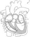
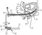
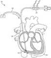
图1是根据一方面,心脏的一剖开透视图,显示本申请的经导管的瓣膜系统位于心脏中;1 is a cutaway perspective view of a heart showing the transcatheter valve system of the present application located in the heart according to one aspect;
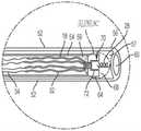
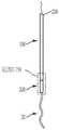
图2是根据一方面,系绳的侧视图,系绳的绳索融合至缝线,系绳连接到图1的经导管的瓣膜的锚固件上;2 is a side view of a tether, the cord of the tether fused to a suture, and the tether attached to the anchor of the transcatheter valve of FIG. 1 , according to an aspect;
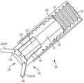
图3A是根据一方面,图1的经导管的瓣膜系统的锚固件递送系统的侧视图;3A is a side view of the anchor delivery system of the transcatheter valve system of FIG. 1 , according to one aspect;
图3B是图3A的锚固件递送系统的放大侧视图;Figure 3B is an enlarged side view of the anchor delivery system of Figure 3A;
图3C是图3A的锚固件递送系统的端视图;Figure 3C is an end view of the anchor delivery system of Figure 3A;
图4A是图3的锚固件递送系统的透视图,其中装置的一部分位于右心室中;Figure 4A is a perspective view of the anchor delivery system of Figure 3 with a portion of the device located in the right ventricle;
图4B是图3的锚固件递送系统的透视图,其中锚固件递送系统正将图2的与锚固件相连的系绳的一部分递送到右心室中;4B is a perspective view of the anchor delivery system of FIG. 3, wherein the anchor delivery system is delivering a portion of the tether connected to the anchor of FIG. 2 into the right ventricle;
图5A是图3的锚固件递送系统的透视图,其中锚固件递送系统正将图2的与锚固件相连的系绳的一部分递送到右心室中;5A is a perspective view of the anchor delivery system of FIG. 3, wherein the anchor delivery system is delivering a portion of the tether connected to the anchor of FIG. 2 into the right ventricle;
图5B是定位在右心室中的、图2的与锚固件相连的系绳的一透视图;Figure 5B is a perspective view of the tether of Figure 2 connected to the anchor positioned in the right ventricle;
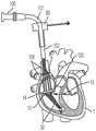
图6A是根据一方面,两条系绳的透视图,各系绳都连接到定位在心脏中的图2的锚固件;6A is a perspective view of two tethers, each connected to the anchor of FIG. 2 positioned in the heart, according to one aspect;
图6B是图6A的两条系绳的放大图,各系绳均连接至锚固件;Figure 6B is an enlarged view of the two tethers of Figure 6A, each tether connected to an anchor;
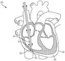
图7A是根据一方面,图1的经导管的瓣膜系统的瓣膜递送系统的透视图,其中瓣膜递送系统的一部分位于右心室中;7A is a perspective view of a valve delivery system of the transcatheter valve system of FIG. 1 , wherein a portion of the valve delivery system is located in the right ventricle, according to one aspect;
图7B是根据一方面,图1的经导管的瓣膜系统的瓣膜的透视图,其中瓣膜通过图7A的瓣膜递送系统定位在三尖瓣环中;7B is a perspective view of a valve of the transcatheter valve system of FIG. 1 , wherein the valve is positioned in the tricuspid annulus by the valve delivery system of FIG. 7A , according to one aspect;
图7C是图7B的瓣膜的端视图;Figure 7C is an end view of the valve of Figure 7B;
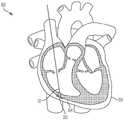
图8A是图1的经导管的瓣膜系统的瓣膜的透视图,其中瓣膜通过图7A的瓣膜递送系统定位在三尖瓣环中;8A is a perspective view of a valve of the transcatheter valve system of FIG. 1, wherein the valve is positioned in the tricuspid annulus by the valve delivery system of FIG. 7A;
图8B是图1的经导管的瓣膜系统的瓣膜的透视图,其中瓣膜已通过图7A的瓣膜递送系统定位在三尖瓣环中;8B is a perspective view of the valve of the transcatheter valve system of FIG. 1, wherein the valve has been positioned in the tricuspid annulus by the valve delivery system of FIG. 7A;
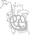
图9A是图1的经导管的瓣膜系统的瓣膜的透视图,其中瓣膜通过多个心房锁定件被锁定在三尖瓣环中的适当位置;9A is a perspective view of a valve of the transcatheter valve system of FIG. 1 , wherein the valve is locked in place in the tricuspid annulus by a plurality of atrial locks;
图9B是图1的经导管的瓣膜系统的瓣膜的透视图,其中瓣膜通过多个心房锁定件被锁定在三尖瓣环中的适当位置;9B is a perspective view of a valve of the transcatheter valve system of FIG. 1, wherein the valve is locked in place in the tricuspid annulus by a plurality of atrial locks;
图10A是根据一方面,图1的经导管的瓣膜系统的心房锁定件的正视图;10A is a front view of an atrial lock of the transcatheter valve system of FIG. 1 according to an aspect;
图10B是图10A的心房锁定件的放大正视图;Figure 10B is an enlarged front view of the atrial lock of Figure 10A;
图11A至图11D是显示图10A的心房锁定件的操作进展的正视图;11A-11D are front views showing the progress of operation of the atrial lock of FIG. 10A;
图12A是根据一方面,图1的经导管的瓣膜系统的心房锁定件的正视图;12A is a front view of an atrial lock of the transcatheter valve system of FIG. 1 according to an aspect;
图12B是图12A的心房锁定件的放大正视图;Figure 12B is an enlarged front view of the atrial lock of Figure 12A;
图13A是图12的心房锁定件的正视图;Figure 13A is a front view of the atrial lock of Figure 12;
图13B是图13A的心房锁定件的剖视图;13B is a cross-sectional view of the atrial lock of FIG. 13A;
图14A至图14D是显示图12的心房锁定件的操作进展的正视图;14A-14D are front views showing the progress of operation of the atrial lock of FIG. 12;
图14E是根据一方面,图1的经导管的瓣膜系统的心房锁定件的透视图;14E is a perspective view of an atrial lock of the transcatheter valve system of FIG. 1 , according to an aspect;
图15A是图1的定位于心脏的经导管的瓣膜系统的透视图,其中缝线保留;15A is a perspective view of the heart-positioned transcatheter valve system of FIG. 1 with sutures retained;
图15B是图1的定位于心脏的经导管的瓣膜系统的透视图,其中所有递送装置都被取回;15B is a perspective view of the heart-positioned transcatheter valve system of FIG. 1 with all delivery devices retrieved;
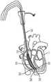
图16是根据一方面,用于将锚固件定位在心包腔中的心外膜系绳系统的透视图;16 is a perspective view of an epicardial tether system for positioning anchors in the pericardial cavity, according to one aspect;
图17是图16的心外膜系绳系统的透视图,其中系统的导管的部分已经进入心包腔;Fig. 17 is a perspective view of the epicardial tether system of Fig. 16, wherein a portion of the catheter of the system has entered the pericardial cavity;
图18是图16的心外膜系绳系统的透视图,其中心包腔已被喷注;Fig. 18 is a perspective view of the epicardial tether system of Fig. 16 with the pericardial cavity injected;
图19是图16的心外膜系绳系统的透视图,其中J形线材已被插入到被喷注的心包腔中;Figure 19 is a perspective view of the epicardial tether system of Figure 16, wherein the J-shaped wire has been inserted into the injected pericardial cavity;
图20是图16的心外膜系绳系统的透视图,其中系统的锚固件递送引导件到达被喷注的心包腔中;20 is a perspective view of the epicardial tether system of FIG. 16 with the anchor delivery guide of the system into the injected pericardial cavity;
图21是图16的心外膜系绳系统的透视图,其中系统的锚固件正被定位在被喷注的心包腔中;21 is a perspective view of the epicardial tether system of FIG. 16 with the system's anchors being positioned in the injected pericardial cavity;
图22是图16的心外膜系绳系统的透视图,其中系统的锚固件已被配置在被喷注的心包腔中;22 is a perspective view of the epicardial tether system of FIG. 16 with the system's anchors deployed in the injected pericardial cavity;
图23是图16的心外膜系绳系统的透视图,其中系统的固件已被配置在被喷注的心包腔中,并且系统的递送装置已经被取回;23 is a perspective view of the epicardial tether system of FIG. 16, wherein the system's firmware has been deployed in the injected pericardial cavity, and the system's delivery device has been retrieved;
图24是根据一方面,用于将锚固件定位在左心室中的心室系绳系统的透视图;24 is a perspective view of a ventricular tether system for positioning an anchor in the left ventricle, according to one aspect;
图25是图24的心室系绳系统的透视图,其中系统的RF线材穿过隔膜并进入左心室;25 is a perspective view of the ventricular tether system of FIG. 24 with the RF wires of the system passing through the septum and into the left ventricle;
图26是图24的心室系绳系统的透视图,其中系统的导管已穿过隔膜并进入左心室;FIG. 26 is a perspective view of the ventricular tether system of FIG. 24 with the catheter of the system passed through the septum and into the left ventricle;
图27是图24的心室系绳系统的透视图,其中系统的J形线材已穿过导管并进入左心室;27 is a perspective view of the ventricular tether system of FIG. 24 with the J-shaped wire of the system passed through the catheter and into the left ventricle;
图28是图24的心室系绳系统的透视图,其中系统的递送引导件到达左心室;28 is a perspective view of the ventricular tether system of FIG. 24 with the delivery guide of the system reaching the left ventricle;
图29是图24的心室系绳系统的透视图,其中系统的递送引导件已穿过隔膜并进入左心室;29 is a perspective view of the ventricular tether system of FIG. 24 with the delivery guide of the system passed through the septum and into the left ventricle;
图30是图24的心室系绳系统的透视图,其中系统的锚固件定位于左心室中;30 is a perspective view of the ventricular tether system of FIG. 24 with the anchor of the system positioned in the left ventricle;
图31是图24的心室系绳系统的透视图,其中系统的锚固件已配置在左心室中;以及31 is a perspective view of the ventricular tether system of FIG. 24 with the anchors of the system deployed in the left ventricle; and
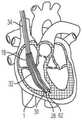
图32是图24的心室系绳系统的透视图,其中系统的锚固件已配置在左心室中,系统的递送装置已被取回。32 is a perspective view of the ventricular tether system of FIG. 24 with the anchor of the system deployed in the left ventricle and the delivery device of the system retrieved.
具体实施方式Detailed ways
通过参考以下详细描述、实施例和权利要求以及其先前和以下描述,可以更容易地理解本发明。在公开和描述本系统、装置和/或方法之前,应当理解,除非另外指明,否则本发明不限于所公开的特定系统、装置和/或方法,因此当然可以加以变化。还应理解,本文所使用的术语仅出于描述特定方面的目的,而无意于进行限制。The present invention can be understood more readily by reference to the following detailed description, examples and claims, together with previous and following descriptions thereof. Before the present systems, devices and/or methods are disclosed and described, it is to be understood that unless otherwise indicated, this invention is not limited to the particular systems, devices and/or methods disclosed as such may, of course, vary. It is also to be understood that terminology used herein is for the purpose of describing particular aspects only and is not intended to be limiting.
提供本发明的以下描述作为本发明当前已知最佳的方面的可行的教导。相关领域的技术人员将认识到,可以对所描述的方面进行许多改变,同时仍然获得本发明的有益结果。还将清楚的是,通过选择本发明的一些特征而不利用其他特征,可以获得本发明的一些期望的益处。因此本领域技术人员将认识到,对本发明的许多修改和调整是可能的,并且在某些情况下甚至可能是想要的,并且是本发明的部分。因此提供以下描述作为对本发明原理的说明,而不是对本发明的限制。The following description of the invention is provided as a practical teaching of the best currently known aspects of the invention. Those skilled in the relevant art will recognize that many changes may be made to the aspects described while still obtaining the beneficial results of the invention. It will also be apparent that some of the desired benefits of the invention may be obtained by selecting some of the features of the invention without utilizing other features. Those skilled in the art will therefore recognize that many modifications and adaptations to the present invention are possible, and may even be desirable in certain circumstances, and are a part of the present invention. The following description is therefore provided as an illustration of the principles of the invention, not as a limitation of the invention.
如本文所用,单数形式的“一(a,an)”和“所述(the)”包括复数指示物,除非上下文另外明确指出。因此,例如,除非上下文另外明确指出,否则对“一系绳”的提及包括具有两条或更多条系绳的方案。As used herein, the singular forms "a, an" and "the" include plural referents unless the context clearly dictates otherwise. Thus, for example, reference to "a tether" includes reference to having two or more tethers unless the context clearly dictates otherwise.
本文的范围可以表示为从“大约(about)”一特定值和/或至“大约”另一特定值。当表达这样的范围时,另一方面包括从一特定值和/或至另一特定值。类似地,当将值表示为近似值时,使用先行词“大约( about)”,将理解特定值形成另一方面。将进一步理解,每个范围的端点相对于另一端点以及独立于另一端点都是显著的。Ranges can be expressed herein as from "about" one particular value, and/or to "about" another particular value. When expressing such a range, another aspect includes from the one particular value and/or to the other particular value. Similarly, when values are expressed as approximations, by use of the antecedent "about," it will be understood that the particular value forms another aspect. It will be further understood that the endpoints of each range are significant relative to the other endpoints as well as independently of the other endpoints.
如本文所使用的,术语“可选的”或“可选地”是指随后描述的情形或情况可能发生或可能不发生,并且所述描述包括所述情形或情况发生的情况和未发生的情况。如本文所用,“流体”是指自由流动的任何物质,包括液体、气体和等离子体。如本文所用,“流体连通”是指允许物质在相关部件之间自由流动的任何连接或相对定位。As used herein, the term "optional" or "optionally" means that the subsequently described situation or circumstance may or may not occur, and that the description includes instances where said situation or circumstance occurs and instances where it does not occur Condition. As used herein, "fluid" refers to any substance that flows freely, including liquids, gases, and plasmas. As used herein, "fluid communication" refers to any connection or relative positioning that permits the free flow of substances between related components.
本文公开的内容涉及一种用于将瓣膜微创地植入心脏1中的医疗组件10,以及所述组件10的各部分的植入方法,以实现对原生心脏瓣膜的置换。图1显示经导管的瓣膜12,根据本文公开的方法和本文公开的医疗组件10,所述经导管的瓣膜12被植入以置换例如原生三尖瓣。所述组件包括一经导管的瓣膜12,所述经导管的瓣膜具有配置用以连接至心房底部16的心房密封裙部14,以及配置用以将所述瓣膜连接至至少一锚固件19(图2)的至少一系绳18,所述锚固件附接到一心内壁,如所示的心室尖20。系绳18可以通过锚固件19锚定到任何心内壁,包括但不限于心室内间隔、右心室尖或右心室游离壁。仅出于讨论的目的显示心室尖20,但是将系绳18锚固到任何心内壁都在本发明的精神和范围内。医疗组件10包括一锚固件递送系统50(在图3A和图3B中显示)和一瓣膜递送组件100(在图7A中示出)。如本文所示和所述的用于植入经导管的三尖瓣的方法通常包括以下步骤:利用锚固件递送系统50来递送锚固件和系绳,以将锚固件固定至心内壁,如心室尖;移除所述锚固件递送系统50;利用瓣膜递送组件100来定位瓣膜和裙部;锁定所述心房裙部;并移除所述瓣膜递送组件100,从而使所述瓣膜置换原生三尖瓣。The content disclosed herein relates to a
瓣膜:Valve :
经导管的瓣膜12的尺寸和配置适于置换右心房2和右心室3之间的三尖瓣,如图1所示。但是可选地,在略微变化的情况下,所述瓣膜的尺寸和构造适于定位在左心房4和左心室5之间的二尖瓣环中。因此,虽然主要是指三尖瓣置换装置、系统和方法,但应理解的是,在稍有变化的情况下,这些装置、系统和方法可用于置换其他瓣膜例如二尖瓣、主动脉瓣,肺动脉瓣等。仅出于讨论的目的,以下描述和附图涉及三尖瓣。关于递送组件和方法,它们可以与任何合适的瓣膜置换装置一起使用和实践。本文的公开内容不限于所示出和描述的瓣膜。The
如图所示,瓣膜12是自膨胀式瓣膜(即所述瓣膜是可压缩的,以便其可通过组件10的导管)。一方面,瓣膜12由镍钛诺和牛、马或猪心包瓣叶19组成,如图7C所示。在另一方面,瓣膜12的瓣膜直径小于或近似等于配置部位13处的瓣环,例如三尖瓣环,从而防止或减少与脆弱的三尖瓣环的并置(apposition)。瓣膜可操作地连接到至少一系绳18,所述系绳包括用于将瓣膜12固定在心脏内的至少一绳索32,如下所述。根据另一方面,如图7C所示,在瓣膜12的外壁17上限定至少一孔15。每个孔15的尺寸和形状被设置成使得系绳的绳索的一部分穿过孔15。因此系绳18的各绳索32被连接到瓣膜而不干扰瓣膜的任何瓣叶19。在另一方面(未显示),瓣膜12可具有沿其外径定位的锚固元件。这些锚固元件允许对三尖瓣瓣叶的附加固定,但不必用作主要的固定机构。再次参照图1,心房密封裙部14围绕经导管的瓣膜12的上端大致上沿周向延伸。裙部14覆盖有一膜,并且其直径大于所述配置部位13处的瓣环(annulus)。密封裙部22的裙部直径可以大于三尖瓣环的直径。在另一方面,心房裙部由(但不限于)选自以下的合成材料所形成:聚碳酸酯(polycarbonate)、聚氨酯(polyurethane)、聚酯(polyester)、膨胀聚四氟乙烯(ePTFE)、聚对苯二甲酸乙二醇酯(expanded polytetrafluoroethylene)(PET)、硅胶(silicone)、天然或合成橡胶,或它们的组合。心房裙部还可覆盖有成年或幼年的牛、羊、马或猪心包。可选地,心房裙部14的至少一部分由替代材料形成,例如但不限于聚氨酯泡沫(polyurethane foam)或可填充食盐水的环,其具有聚合物交换能力,以固化所述环。As shown,
在一方面,心房密封裙部14还包括至少一心房锚固件238,诸如突出穿过所述锚固件的出口242的部件,以允许在心房中的稳定性。因此例如在心室锚固功能障碍等情况 下,在心房中的稳定性可防止瓣膜12的逆行迁移(retrograde migration)。In one aspect, the
在另一方面,心房密封裙部14的至少一部分具有一个或多个固定构件24,如图15B所示的沿着心房密封裙部14的下边缘定位的固定构件2,从而允许进一步锚固到右心房底部16和/或在三尖瓣环的心房侧上的其他部分,防止瓣膜12迁移到近侧的右心房2中,从而防止假体的不稳定性(例如摇摆)和瓣周反流。而且心房裙部14顺应心房底部的形貌,包括覆盖和密封心内导线(如永久起搏器导线( permanent pacemaker leads))的能力。心房裙部14密封导线并防止导线周围反流的能力将这种经导管的瓣膜系统与其他经导管的三尖瓣修复系统区分开来。In another aspect, at least a portion of the
系绳和锚固件:Tethers and anchors :
现在参考图2,至少一系绳18可操作地连接到所述置换瓣膜12并将所述瓣膜12连接到所述锚固件19。所述系绳18包括至少一绳索32,并且每条绳索32连接至缝线34。锚固件19包括一锚固螺钉28和一锚固帽30。在一方面,锚固螺钉连接至锚固帽的远端36并从锚钉帽的远端36延伸,并且系绳18的至少一绳索32连接至锚固帽30的近端38,并从锚固帽30的近端38延伸。也就是说,锚固帽30位于锚固螺钉28和绳索32之间。锚固螺钉锚固螺钉28配置用以将系绳18牢固地连附到心脏内壁,例如心脏1的心室尖20(ventricular apex)。例如锚固螺钉28是一主动锚固螺钉,包括螺纹或线圏,其牢固地旋转进入心室尖。锚固件经由锚固螺钉配置用以将系绳牢固地连附到心脏内壁,例如心脏的心室尖20,而不会延伸穿过心尖和心脏外部。因此,在这个方面,组件10基本上没有任何部分完全穿透和/或完全延伸穿过心脏壁的任何部分,并且不需要经过心尖的通路(trans-apical access)。在另一方面(未显示),作为锚固螺钉28的替代,一固定机构(由(但不限于)镍钛合金、不锈钢、钴铬合金或钛合金制成,呈倒刺( barbs)、钩形( hooks)、叉形( prongs)等)定位在锚固帽30的远端36处,以将系绳18牢固地连附到心脏1的心室尖20,而不会延伸穿过心尖和心脏的外部。Referring now to FIG. 2 , at least one
至少一绳索32具有一连接至锚固帽30的一部分的远端40、以及连接至缝线34的近端42。一方面,绳索为坚固而柔韧的绳索,例如但不限于,膨胀聚四氟乙烯(polytetrafluoroethylene,ePTFE)或超高分子量聚乙烯(UHMWPE或UHMW)的绳索。在使用中(以下将更全面地描述),绳索32的中央部分(在远端和近端之间)延伸穿过和/或连接到瓣膜12,以将瓣膜保持在相对于三尖瓣环的期望位置。At least one
锚固件递送系统:Anchor Delivery System :
现在参照图3A至图3C、图4A和图4B,显示用于将锚固件19的锚固帽30定位和配置在期望位置的锚固件递送系统50。递送系统50包括一锚固件递送引导件52和一锚固件递送杆54。在这个方面,锚固件递送引导件52具有远端56、一相对的近端58和一内部引导件管腔57,所述内部引导件管腔57在所述锚固件递送引导件末端60和所述相对的近端58之间延伸,并且配置用以使得所述锚固件递送杆54的至少一部分延伸穿过其中。在另一方面,所述锚固件递送引导件52的至少一部分是柔性的,使得在锚固件递送引导件52的远端处的末端60定位在一心内壁锚固部部位62处或附近,例如心室尖20。Referring now to FIGS. 3A-3C , 4A and 4B, there is shown an
所述锚固件递送杆54配置用以将锚固螺钉28牢固地连附到锚固部位62。锚固件递送杆54具有一远端64、一相对的近端66和在其间延伸的内部杆件管腔59,内部杆件管腔59的尺寸和配置使得至少一系绳18的至少一部分被插入穿过其中。在另一方面,所述锚固件递送杆54的至少一部分是柔性的,使得在锚固件递送杆54的远端处的杆件末端68定位在心内壁锚固部位62,例如心室尖20处或附近。The
如图3B所示,在锚固件递送杆54的杆件末端68中定义了一孔或凹座70。所述凹座的尺寸和配置可使其与锚固帽30配合。即,锚固帽的至少一部分定位在凹座70中,使得凹座的壁72与锚固帽配合。因此,例如当将锚固帽30放置在凹座70中并与之配合时,锚固件递送杆54的旋转使锚固帽30旋转。因此,凹座配合锚固帽30,并且锚固螺钉28从锚固件递送杆54向远侧延伸,如图3B所示杆。在另一方面,当凹座70配合锚固帽30时,至少一绳索32和至少一缝线34的至少一部分延伸穿过锚固件递送杆54的内部杆件管腔。As shown in FIG. 3B , a hole or
锚固件递送系统50还包括一引导件手柄74,所述引导件手柄74具有连接至所述锚固件递送引导件52的偏移旋钮76。引导件手柄和偏移旋钮被配置并用以帮助将所述锚固件递送引导件的末端60引导至心内壁锚固部位62,例如心室尖20。如图3A所示,所述锚固件递送系统50包括连接到锚固件递送杆54的杆件手柄78。在使用中(下文将更全面地描述),当锚固帽30被接收在凹座70内时,杆件手柄78的旋转相应地旋转杆件末端68和锚固帽30。The
锚固件递送系统50包括一护套80,所述护套80可移除地连接至锚固件递送引导件52。所述护套80与锚固件引导件52流体连通,从而使诸如二氧化碳之类的流体通过所述护套围绕所述锚固件引导件。一中央护套通道84由护套80所限定,所述中央护套通道84与所述锚固件递送引导件52连通,使得所述锚固件杆递送杆54和其他系统部件延伸穿过所述中央护套通道84。The
锚固件递送系统50可选地包括J形线材82,如图7A、图7B、图8A和图8B所示,用户可将其引导到锚固部位62。所述J形线材例如为(但不限于)0.025英寸或0.035英寸的J形线材。当然可以考虑具有其他直径的J形线材。如同在任何过线系统中一样,首先将J形线材通过护套80引入右心房3中,穿过配置部位13进入右心室3中,到达锚固部位62。通过为锚固件递送引导件52提供路径以跟随其到达最终目标,J形线材增加所述步骤的效率和安全性。The
锚固件递送方式:Anchor delivery method:
为了将瓣膜12安装在三尖瓣环中,如图4A所示,将用作引导线的J形线材82插入右颈内静脉,进入右心房并到达所述锚固植入部位62。锚固件递送系统50由用户沿着先前植入的J形线材82的长度引导至心内壁锚固部位62,例如心室尖20。在锚固件递送引导件52的远端56处的所述锚固件递送引导件末端60被定位在诸如心室尖的锚固部位处或附近。如图3A所示,杆连接到所述锚固件19的所述锚固帽30和锚固螺钉28的锚固件递送杆54和系绳18定位于所述锚固件递送引导件52的内部引导件管腔57内。锚固帽30连接至锚固件递送杆54的远端64,而系绳18的绳索32位于锚固件递送杆54的管腔59中。锚固件递送杆54通过锚固件递送引导件52的内部引导件管腔向远侧推进,直到连接到锚固件杆递送杆54的远端的锚固帽30定位在心内壁锚固部位62(例如心室尖20)处或附近。To install the
如图4B所示,在锚固件19的锚固螺钉28(通过锚固帽30连接到系绳18)定位在邻近锚固部位62的情况 下,锚固件递送杆54的近端66旋转以引起锚固帽30的相应旋转。例如,所述旋转手柄78沿第一方向旋转以引起锚固帽的相应旋转。连接至锚固帽30的锚固螺钉也旋转并旋入心内壁锚固部位62(例如心室尖20)的一部分,直到锚固帽的远端36与心内壁相邻和/或系绳被牢固地连接到心内壁。值得注意的是,在此位置,锚固螺钉28没有完全延伸穿过心脏壁的任何部分,并且不需要经过心尖的通路。在将锚固帽30放置在期望位置时,锚固件递送系统50的锚固件递送杆54和锚固件递送引导件52从心脏1取回,如图5A所示。这样在图5B中,连接至锚固帽30的系绳18的绳索32由锚固件19的锚固螺钉28固定,并保持在右心室内,并且使用瓣膜递送系100。As shown in FIG. 4B , with the
如图5B所示,在放置锚固件19的锚固帽30之后,系绳18的至少一根绳索32从锚固帽延伸穿过三尖瓣环并进入右心房2。缝线34连接到各绳索的近端并延伸穿过上(或下)腔静脉并离开心脏1。After the
如果递送一个以上的与锚固件19连接的系绳18,则各锚固件19都通过其锚固螺钉28而固定,并且重复此过程,直到所有与锚固件连接的系绳都已牢固地连接到心脏壁上为止。一方面如图6A和图6B所示,所述组件10利用两个锚固件和系绳,三个锚固件和系绳,四个锚固件和系绳,或者也可以考虑更多的锚固件和系绳。If more than one
在将锚固螺钉28固定至心室尖和系绳18的情况 下,现在可以利用瓣膜递送组件100来引入和定位瓣膜12。With the
瓣膜递送系统:Valve Delivery System :
现在参考图7A和图7B,显示用于将瓣膜12定位和配置在期望的配置部位13处的瓣膜递送组件100。如图所示,瓣膜递送组件100包括瓣膜递送引导件102、鼻锥104、瓣膜配置旋钮106和至少一心房定位杆108。在这个方面,瓣膜递送引导件具有一远端110、一相对的近端112以及在其间延伸的内部引导件管腔114,所述内部引导件管腔的尺寸和配置适于使得瓣膜12和其他系统部件延伸穿过其中。在另一方面,瓣膜递送引导件102的至少一部分是柔性的,使得在瓣膜递送引导件的远端处的末端116被定位以越过所述配置部位13并进入右心室3。Referring now to FIGS. 7A and 7B , there is shown a
瓣膜配置旋钮106连接到瓣膜递送引导件102的近端112。中央通道118由瓣膜配置旋钮106限定,并且与内部引导件管腔114流体连通,使得心房定位杆108、J形线材82和/或至少一缝线34延伸穿过中央通道118并进入内部引导件管腔114。在另一方面,瓣膜配置旋钮106可旋转并配置用以使得旋钮106在第一方向上的旋转导致瓣膜12周围的护套102被去除。鼻锥104可以是传统的鼻锥,其联接至瓣膜递送引导件102并且配置用以将瓣膜12引导至所述配置部位13。
参考图8A和图8B,至少一心房定位杆108具有一远端120、一相对的近端122和在其之间延伸的内部杆件管腔124,所述内部杆件管腔的尺寸和配置使得缝线34和/或绳索32的一部分穿过其中插入。在另一方面,心房定位杆108的至少一部分是柔性的,使得心房定位杆的远端120定位在配置部位13处或附近。8A and 8B, at least one
心房裙部锁定件:Atrial Skirt Lock:
至少一心房定位杆108包括一可拆卸的锁定件126,所述可拆卸的锁定件126定位在所述心房定位杆的远端120上或附近,如图9至图14所示。在一方面,所述可拆卸的锁定件将至少一绳索32牢固地连接到右心房2的一部分。因此绳索的远端40牢固地连接到右心室3中的锚固帽30,并且可拆卸的锁定件126在右心房牢固地连接绳索32。At least one
图10A、图10B和图11A至图11D显示所述可拆卸的锁定件126的一实施例。在一个方面,锁定件具有第一端128、一相对的第二端130和侧壁132,它们配合以限定一中央空腔134。在另一方面,所述第一端带有螺纹并被配置用以与心房定位杆108的远端120上的互补螺纹配合接合。开口136限定在锁定件126的第一端和第二端中的每一个,以使得绳索32的一部分延伸穿过两个开口并穿过中央空腔。在使用中(下面将更全面地描述),通过在第一方向上旋转杆心房定位杆108,以将所述可拆卸的锁定件选择性地连附到所述心房定位杆,并且通过在第二方向上旋转杆心房定位杆108,以将可拆卸的锁定件126选择性地从心房定位杆拆卸,所述第二方向与第一方向相反。10A , 10B and 11A-11D show an embodiment of the
在一方面,所述可拆卸的锁定件126还包括可在第一锁定位置和第二解锁位置之间运动的夹具138,在第一锁定位置中,夹具的一部分将绳索32固定在一期望位置,在第二解锁位置中,夹具没有将绳索固定在所述期望位置。诸如弹簧等的偏压构件140配置用以将夹具138推压到第一锁定位置。远离所述心房定位杆108的远端120延伸的凸片135或其他突起配置为当可拆卸的锁定件连附到杆心房定位杆108时,将夹具保持在第二解锁位置。In one aspect, the
图12A至图14D显示一可拆卸的锁定件226的另一个实施例。在一方面,锁定件具有一第一端228、一相对的第二端230和一侧壁232,它们共同限定一中央空腔234。所述第一端具有螺纹并配置用以与心房定位杆108的远端120上的互补螺纹配合接合。在锁定件226的第一端和第二端中的各者中限定有开口236,使得绳索32的一部分延伸通过两个开口和中央空腔。在使用中(下面将更全面地描述),通过在第一方向上旋转杆心房定位杆108,以将可拆卸的锁定件选择性地连附到心房定位杆并且通过在第二方向上旋转杆心房定位杆108,以将可拆卸的锁定件226选择性地从心房定位拆卸,所述第二方向与第一方向相反。12A to 14D show another embodiment of a
在一方面,可拆卸的锁定件226还包括一心房锚固件238,所述心房锚固件238可在第一锁定位置和第二解锁定位置之间运动,在第一锁定位置中,心房锚固件的一部分将绳索32固定在一期望位置,在第二解锁位置中,心房锚固件没有将绳索32固定在所述期望位置。诸如弹簧等的偏压构件240配置用以将心房锚固件238推压到第一锁定位置。远离所述心房定位杆108的远端120延伸的凸片135或其他突起配置为当可拆卸的锁定件连附到杆心房定位杆108时,将心房锚固件保持在第二解锁位置。In one aspect, the
在一方面,在可拆卸的锁定件226的侧壁232的一部分中限定锚固件出口242。在这方面,锚固件出口的尺寸和形状使得在第一锁定位置,定位在心房锚固件末端246的钩件244或其他抓握元件延伸穿过出口242到中央空腔234的外部。在使用中,在第一锁定位置,钩件牢固地锚固所述可拆卸的锁定件(因此也牢固地锚固绳索32)至心室2的一部份。现在参见图15,组件10还包括缝线切割器148,缝线切割器148的尺寸和配置用以通过瓣膜递送护套80而穿过至少一缝线34,以切割至少一缝线34。In one aspect, an
在使用中,组件10通过首先放置右心室锚固件而以经导管方法植入瓣膜12。瓣膜位置将不需要将系绳18拉过如心脏1的心室尖20之类的心内壁,因为瓣膜12在系绳上自由运动直到达到期望的瓣膜位置。在达到期望的瓣膜位置之后,至少一心房定位杆108将心房密封裙部14推到适当位置,并且通过在各个定位杆的端部处的可拆卸的锁定件126、226锁定就位。瓣膜被重新定位或取回,直到释放穿过各心房定位杆108的缝线34为止。In use,
图14E显示一可拆卸的锁定件526的另一实施例。在一方面,锁定件具有一第一端528、一相对的第二端530和一侧壁532,它们共同限定一中央空腔534。在另一方面,所述第一端具有螺纹并配置用以与心房定位杆108的远端120上的互补螺纹配合接合。在锁定件526的第一端和第二端中的各者中限定有开口536,使得绳索32的一部分延伸通过两个开口和中央空腔。在使用中(下面将更全面地描述),通过在第一方向上旋转杆心房定位杆108,以将可拆卸的锁定件选择性地连附到心房定位杆,并且通过在第二方向上旋转杆心房定位杆108,以将可拆卸的锁定件526选择性地从心房定位杆拆卸,所述第二方向与第一方向相反。FIG. 14E shows another embodiment of a
在一方面,可拆卸的锁定件526还包括至少心房锚固件538,所述心房锚固件538可在第一锁定位置和第二解锁定位置之间运动,在第一锁定位置中,心房锚固件的一部分将绳索32固定在一期望位置,在第二解锁位置中,心房锚固件没有将绳索32固定在所述期望位置。可选地,心房锚固件包括第一心房锚固件542和第二心房锚固件544。在另一方面,心房锚固件包括凸轮杠杆臂(cam ever arm)。诸如弹簧等的偏压构件540配置用以将心房锚固件538推压到第一锁定位置。远离所述心房定位杆108的远端120延伸的凸片135或其他突起配置为当可拆卸的锁定件连附到杆心房定位杆108时,将心房锚固件保持在第二解锁位置。In one aspect, the
在一方面,在可拆卸的锁定件526的侧壁532的一部分中限定锚固件出口546。在这方面,锚固件出口的尺寸和形状使得在第一锁定位置,心房锚固件546的一部份548延伸穿过出口546到中央空腔534的外部。在使用中,在第一锁定位置,心房锚固件牢固地锚固所述可拆卸的锁定件(因此也牢固地锚固绳索32)至心室2的一部份。In one aspect, an
现在参见图15,组件10还包括一缝线切割器148,缝线切割器148的尺寸和配置用以通过瓣膜递送护套80而穿过至少一缝线34,以切割至少一缝线34。Referring now to FIG. 15 ,
膜递送和定位方法:Membrane Delivery and Localization Methods :
在使用中,组件10通过首先放置右心室锚固件而以经导管方法植入瓣膜12。瓣膜位置将不需要将系绳18拉过如心脏1的心室尖20之类的心内壁,因为瓣膜12在系绳上自由运动直到达到期望的瓣膜位置。在达到期望的瓣膜位置之后,至少一心房定位杆108将心房密封裙部14推到适当位置,并且通过在各个定位杆的端部处的可拆卸的锁定件126、226锁定就位。瓣膜被重新定位或取回,直到释放穿过各心房定位杆108的缝线34为止。In use,
现在参考图7A,然后可以将瓣膜递送组件100插入J形线材82上并进入心脏的一部分中。在瓣膜递送引导件102到达心脏的途中插入到护套80中之前,将瓣膜12预加载到瓣膜递送引导件102的远端110中。缝线34的至少一部分穿过在瓣膜12的外壁17上所限定的至少一孔15,如图7B和图7C所示,进入瓣膜递送引导件102的内部引导件管腔114。当在远端110内的瓣膜12与瓣膜递送引导件102为一整体在J形线材82上移动,至少一绳索的一部分可以延伸穿过并远离瓣膜递送引导件的远端110,并且至少一缝线的一部分可以延伸穿过并远离瓣膜递送引导件102的近端112。定位所述瓣膜递送引导件,使得瓣膜递送引导件102的远端处的末端116穿过所述配置部位13并进入右心室3。Referring now to FIG. 7A ,
已经预加载到瓣膜递送引导件102的远端110中的瓣膜12位于配置部位13。在一方面,并且在插入到瓣膜递送引导件中之前,各个缝线34穿过限定在瓣膜12的外壁17上的至少一孔15,如图7B和图7C所示。在另一方面,在心房密封裙部14中限定的多个类似的孔(未显示),使得各个缝线穿过在密封裙部中限定的孔。当瓣膜12和瓣膜递送引导件102作为一整体朝着所述配置部位移动时,瓣膜12将到达缝线的端部,并且绳索32的一部分将穿过在瓣膜中所限定的孔15。一方面,瓣膜12和瓣膜递送引导件102可在至少一绳索上上下滑动,直到到达期望的配置部位13为止。即瓣膜在绳索32上自由浮动,直到被可拆卸的锁定件126、226锁定到位。
应当理解,在瓣膜12处于期望的配置部位13中的情况下,瓣膜配置旋钮106取回所述瓣膜递送引导件102的远端110,同时瓣膜12保持固定在适当的位置,从而将瓣膜12“脱鞘(unsheathing)”,因此,瓣膜和/或心房密封裙部14将扩张至其完整的未压缩尺寸。可选地,在一方面,因为瓣膜的位置被调整,所以瓣膜配置旋钮106用于取回瓣膜递送引导件102的远端10,从而将瓣膜12“脱鞘(unsheathing)”,使得瓣膜和/或裙部扩张至其完整的未压缩尺寸,而瓣膜处于期望的配置部位附近。It should be appreciated that with the
然后心房定位杆108被插入各个缝线34上,使得各个缝线的一部分在内部杆件管腔124中,并且各个缝线的一部分从定位杆的近端122延伸。参考图8A和图8B,将定位杆108插入穿过瓣膜递送引导件102,直到绳索32的一部分进入内部杆件管腔,并且定位杆的远端120(可拆卸的锁定件126、226固定在其上)在邻近心房密封裙部14处。用户将定位杆108向下推,直到密封裙部相对于三尖瓣环处于期望的位置。当密封裙部14和瓣膜12在配置部位13的期望位置时,用户将各个缝线34拉紧,这又将拉动松弛部分通过内部杆件管腔124,直到拉紧各个绳索32。例如,从心房定位杆的近端122延伸的缝线的端部被用户拉动以调节相应的绳索中的张力。在一方面,通过调节施加到缝线34上的作用力,以将不同的张力施加到绳索32上。例如,如果用户比拉动第二缝线34更用力地拉动第一缝线,则对应于第一缝线的绳索32的张力大于连接到第二缝线34的绳索中的张力。
现在参考图9A和图9B,然后使各个心房定位杆108沿第一方向旋转,以将各个可拆卸的锁定件126、226分别锁定在心房密封裙部14和绳索32上。因此瓣膜12被可拆卸的锁定件锁定在三尖瓣环的心房侧。沿第一方向的继续旋转,将锁定件126、226与定位杆分离。当锁定件已经从定位杆108上脱离时,所述定位杆108杆通过瓣膜递送引导件102从心脏1取回。在定位杆108取回的情况下,至少一系绳18的绳索32将瓣膜连接至心内锚固壁部,例如心室尖20。处于锁定位置的可拆卸的锁定件126、226防止绳索的近端42相对于密封裙部14移动,从而将瓣膜12牢固地固定在所述配置部位13中。Referring now to FIGS. 9A and 9B , each
如图15A和图15B所示,在将瓣膜12牢固地固定在配置部位13中的情况下,缝线切割器148在缝线34上前进并到达可拆卸的锁定件26、226。然后,缝线切割器在可拆卸的锁定件正上方切割各缝线的远端。然后从心脏1移除缝线和缝线切割器。With the
一方面,在切割缝线34之前,将瓣膜12取回或重新定位。例如如果确定要移除或重新定位瓣膜,则将心房定位杆108定位在各个缝线上,使得缝线的一部分在内部杆件管腔124中。当定位杆108的远端120与可拆卸的锁定件126、226相邻或与其接触时,定位杆108在与第一方向相反的第二方向上的旋转将可拆卸的锁定件连附到定位杆的远端。沿第二方向的继续旋转将锁定件从绳索32解锁。在解锁各个绳索的情况下,将瓣膜从配置部位13移除和/或重新定位在所述配置部位13中。In one aspect,
在另一方面,可在瓣膜配置后数天至数周将瓣膜12重新定位和/或移除。在这方面,缝线不被切割,而是缠绕在一线轴或其他缠绕装置(wrapping device)上。然后将所述装置连接到瓣膜12的心房裙部14。在瓣膜配置并完成手术几天后,可以重新捕获线轴/缠绕装置,从而可以解开缠绕(un-wrapping)并取回缝线。然后将心房定位杆108定位在各缝线上,以使缝线的一部分位于内部杆件管腔124内。当定位杆的远端120与可拆卸的锁定件126,226相邻或与其接触时,在与第一方向相反的第二方向上旋转所述定位杆108将可拆卸的锁定件连附到定位的远端。沿第二方向的继续旋转将锁定件从绳索32解锁。在解锁各个绳索的情况下,将瓣膜从配置部位13移除和/或重新定位在所述配置部位13中。In another aspect,
心外膜系绳系统:Epicardial Tether System :
在图16至图23所示的一实施例中,组件10包括一心外膜系绳系统300,用于将锚固件302定位在心包腔304中。在一方面,心外膜系绳包括一导管306、一CO2气体管线308和一歧管(manifold)310。在另一方面,导管是一微导管,具有一远端312,所述远端312被配置用以被拧入和/或以其他方式被推动通过心脏1的壁的至少一部分。如图16所示,微导管的远端接合心脏的心内膜314。微导管306还具有与远端相对的一近端316和内部导管管腔318。微导管的近端连接到CO2气体管线308和歧管310,使得CO2气体管线和歧管310与内部导管管腔密封流体连通。In one embodiment shown in FIGS. 16-23 ,
现在参考图17,将微导管306的远端312推动穿过心脏壁,直到微导管的远端被心包320定位在心包腔304中。造影剂322从歧管310注入通过内部导管管腔318并进入心包腔,以验证微导管306的远端312在心包腔304中。Referring now to FIG. 17 , the
一旦将微导管306的远端312定位在心包腔304中,将二氧化碳从CO2气体管线308注入通过内部导管管腔318并进入心包腔304,以喷注所述心包腔,如图18所示。Once the
一方面,然后如图19所示,将J形线材82推进穿过内部导管管腔318并进入心包腔304。在J形线材就位的情况下,将导管306从心脏1上取下。In one aspect, the J-shaped
在另一方面,如图20和图21所示,将锚固件递送引导件52插在J形线材82上,直到锚固件递送引导件的远端56处的末端60定位在心包腔304中的一锚固部位324处或附近。将锚固件递送杆54插入穿过锚固件递送引导件52的内部引导件管腔,直到锚固件递送杆的远端64位于心包腔304中。In another aspect, as shown in FIGS. 20 and 21 , the
心外膜系绳系统300的锚固件302连接到锚固件递送杆54的远端64。一方面,所述锚固件是自膨胀的(即所述锚固件是可压缩的,以使其适合通过锚固件递送引导件52的内部引导件管腔)。如图21和图22所示,当位于所述锚固件递送杆的远端上的锚固件302到达心包腔304时,锚固件扩张至其全部尺寸,从而将锚固件302锁定在适当的位置。锚固件的左心室部分326延伸穿过心内膜并进入左心室。The
在一方面,在配置到心包腔304中之前,至少一绳索32连接到锚固件302。例如绳索被连接到锚固件,使得绳索被定位在锚固件递送杆54的内部杆件管腔中。因此,如图23所示,当从心脏移除锚固件递送杆时,绳索从心包腔中的锚固件302延伸穿过三尖瓣环和上(或下)腔静脉到达心脏外部。然后在该方面中,如前所述,将瓣膜12、可拆卸的锁定件126、226、缝线34等连接至绳索32。然而在插入时将锚固件从瓣膜上解开(untethered)或者分离(uncoupled),这也在本发明的范围内。可以理解,心包腔304中的二氧化碳被吸收并且心包回到其正常位置。In one aspect, at least one
心室间系绳系统:Interventricular Tether System :
在另一实施例中,如图24至图32中所示,组件10包括一心室间系绳系统400,用于将锚固件402定位在左心室5中。在一方面,心室间系绳系统的系绳包括导管406、射频(radiofrequency,RF)产生器408和电性耦合到RF产生器的RF线材410。在另一方面,所述导管是一线材递送导管,其具有一远端412,所述远端412配置用以定位在邻近或靠近心脏1的隔膜7。在使用中,由RF产生器408产生的RF促使RF线材的远端414穿过隔膜,从右心室3移动进入左心室5,如图24和图25所示。In another embodiment, as shown in FIGS. 24-32 ,
现在参考图26,然后将导管406推入左心室5。例如,如果导管的远端412的一部分带有螺纹,则导管406的旋转将推动所述远端穿过隔膜7进入左心室。在导管的一部分位于左心室中的情况下,RF线材被取回并将J形线材82插入穿过导管406,直到J形线材的一部分在左心室5中,如图27所示。Referring now to FIG. 26 , the
在另一方面,如图28和图29所示,将锚固件递送引导件52插在J形线材82上,直到在锚固件递送引导件的远端56处的末端60定位在左心室5中的锚固部位416处或附近。锚固件递送杆54插入穿过锚固件递送引导件52的内部引导件管腔,直到锚固件递送杆的远端64位于左心室中,如图30所示。In another aspect, as shown in FIGS. 28 and 29 , the
心室间系绳系统400的锚固件402被连接到锚固件递送杆54的远端64。一方面,所述锚固件是自膨胀的(即所述锚固件是可压缩的,以使其适合通过锚固件递送引导件52的内部引导件管腔)。如图31和图32所示,当位于所述锚固件递送杆的远端上的锚固件402到达左心室5时,锚固件离开锚固件递送引导件的内部引导件管腔并且扩张至其全部尺寸,从而将锚固件402锁定在适当的位置。如在图32所述,锚固件的右心室部分418延伸穿过隔膜7并进入右心室3。The
在一方面,在配置到左心房3中之前,至少一绳索32连接到锚固件402的右心室部分418。例如绳索被连接到锚固件,使得绳索被定位在锚固件递送杆54的内部管腔中。因此如图32所示,当从心脏1移除锚固件递送杆时,绳索从锚固件402的右心室部分延伸穿过三尖瓣环。然后在这方面中,如前所述,将瓣膜12、可拆卸的锁定件126、226等连接至绳索32。然而在插入时将锚固件从瓣膜上解开(untethered)或者分离(uncoupled),这也在本发明的范围内。In one aspect, at least one
在另一方面,心室间锚固件402是类似于锚固螺钉28的螺钉,或者是由但不限于镍钛诺、不锈钢、钴铬或钛合金组成的固定机构,其形状呈倒刺( barbs)、钩形( hooks)、叉形( prongs)。这种类型的心室间锚固件可以由锚固件递送杆54经由锚固件递送引导件52递送。In another aspect, the
尽管在以上说明书中公开了本发明的几个方面,但是本领域技术人员可以理解,受益于前述说明书和相关附图中呈现的教示,许多修改和其他方面都包括在本发明中。因此应当理解,本发明不限于以上公开的特定方面,并且许多修改和其他方面旨在被包括在所附权利要求的范围内。此外,尽管本文以及随后的权利要求书中采用了特定术语,但是它们仅以一般性和描述性意义使用而不是为了限制所描述的发明。Although several aspects of the invention have been disclosed in the foregoing specification, those skilled in the art will appreciate that many modifications and other aspects are encompassed in the present invention having the benefit of the teachings presented in the foregoing specification and the associated drawings. It is therefore to be understood that the inventions are not to be limited to the particular aspects disclosed above and that modifications and other aspects are intended to be included within the scope of the appended claims. Furthermore, although specific terms are employed herein and in the claims that follow, they are used in a generic and descriptive sense only and not for limitation of the invention as described.
Claims (32)
Priority Applications (1)
| Application Number | Priority Date | Filing Date | Title |
|---|---|---|---|
| CN202310004269.6ACN116115390A (en) | 2017-04-05 | 2018-04-03 | Medical assembly |
Applications Claiming Priority (7)
| Application Number | Priority Date | Filing Date | Title |
|---|---|---|---|
| US201762481846P | 2017-04-05 | 2017-04-05 | |
| US62/481,846 | 2017-04-05 | ||
| US201762509587P | 2017-05-22 | 2017-05-22 | |
| US62/509,587 | 2017-05-22 | ||
| US201762558315P | 2017-09-13 | 2017-09-13 | |
| US62/558,315 | 2017-09-13 | ||
| PCT/US2018/025971WO2018187390A1 (en) | 2017-04-05 | 2018-04-03 | Transcatheter atrial sealing skirt, anchor, and tether and methods of implantation |
Related Child Applications (1)
| Application Number | Title | Priority Date | Filing Date |
|---|---|---|---|
| CN202310004269.6ADivisionCN116115390A (en) | 2017-04-05 | 2018-04-03 | Medical assembly |
Publications (2)
| Publication Number | Publication Date |
|---|---|
| CN110730633A CN110730633A (en) | 2020-01-24 |
| CN110730633Btrue CN110730633B (en) | 2023-01-20 |
Family
ID=63710530
Family Applications (7)
| Application Number | Title | Priority Date | Filing Date |
|---|---|---|---|
| CN202310004269.6APendingCN116115390A (en) | 2017-04-05 | 2018-04-03 | Medical assembly |
| CN201880034100.2AActiveCN110730633B (en) | 2017-04-05 | 2018-04-03 | Transcatheter valve, anchor, tether implant assembly |
| CN202310004290.6APendingCN116059008A (en) | 2017-04-05 | 2018-04-04 | Atrial sealing skirt |
| CN201880033804.8AActiveCN110799102B (en) | 2017-04-05 | 2018-04-04 | Transcatheter atrial sealing skirt, anchor, tether implant assembly |
| CN202310004288.9APendingCN116077238A (en) | 2017-04-05 | 2018-04-04 | Medical assembly |
| CN202310004287.4APendingCN116059007A (en) | 2017-04-05 | 2018-04-04 | Intracardiac anchor assembly |
| CN202310004292.5APendingCN116059009A (en) | 2017-04-05 | 2018-04-04 | Intracardiac anchor assembly and epicardial anchor assembly |
Family Applications Before (1)
| Application Number | Title | Priority Date | Filing Date |
|---|---|---|---|
| CN202310004269.6APendingCN116115390A (en) | 2017-04-05 | 2018-04-03 | Medical assembly |
Family Applications After (5)
| Application Number | Title | Priority Date | Filing Date |
|---|---|---|---|
| CN202310004290.6APendingCN116059008A (en) | 2017-04-05 | 2018-04-04 | Atrial sealing skirt |
| CN201880033804.8AActiveCN110799102B (en) | 2017-04-05 | 2018-04-04 | Transcatheter atrial sealing skirt, anchor, tether implant assembly |
| CN202310004288.9APendingCN116077238A (en) | 2017-04-05 | 2018-04-04 | Medical assembly |
| CN202310004287.4APendingCN116059007A (en) | 2017-04-05 | 2018-04-04 | Intracardiac anchor assembly |
| CN202310004292.5APendingCN116059009A (en) | 2017-04-05 | 2018-04-04 | Intracardiac anchor assembly and epicardial anchor assembly |
Country Status (13)
| Country | Link |
|---|---|
| US (4) | US10820991B2 (en) |
| EP (4) | EP3606444B1 (en) |
| JP (6) | JP7179012B2 (en) |
| KR (4) | KR102339027B1 (en) |
| CN (7) | CN116115390A (en) |
| AU (7) | AU2018248410B2 (en) |
| BR (4) | BR122020023074B1 (en) |
| CA (3) | CA3059102C (en) |
| IL (3) | IL297339A (en) |
| SG (2) | SG11201909246YA (en) |
| UY (2) | UY37667A (en) |
| WO (2) | WO2018187390A1 (en) |
| ZA (2) | ZA201907132B (en) |
Families Citing this family (66)
| Publication number | Priority date | Publication date | Assignee | Title |
|---|---|---|---|---|
| US20090276040A1 (en)* | 2008-05-01 | 2009-11-05 | Edwards Lifesciences Corporation | Device and method for replacing mitral valve |
| US9554897B2 (en) | 2011-04-28 | 2017-01-31 | Neovasc Tiara Inc. | Methods and apparatus for engaging a valve prosthesis with tissue |
| US9308087B2 (en) | 2011-04-28 | 2016-04-12 | Neovasc Tiara Inc. | Sequentially deployed transcatheter mitral valve prosthesis |
| CA3007660A1 (en) | 2015-12-15 | 2017-06-22 | Neovasc Tiara Inc. | Transseptal delivery system |
| US11833034B2 (en) | 2016-01-13 | 2023-12-05 | Shifamed Holdings, Llc | Prosthetic cardiac valve devices, systems, and methods |
| US10433952B2 (en) | 2016-01-29 | 2019-10-08 | Neovasc Tiara Inc. | Prosthetic valve for avoiding obstruction of outflow |
| CA3042588A1 (en) | 2016-11-21 | 2018-05-24 | Neovasc Tiara Inc. | Methods and systems for rapid retraction of a transcatheter heart valve delivery system |
| CN110337280A (en)* | 2017-02-17 | 2019-10-15 | 株式会社田端心脏医学研究 | Artificial heart valve |
| DE102017002974B4 (en)* | 2017-03-28 | 2024-08-08 | Immanuel Albertinen Diakonie Ggmbh | Heart valve implant, suitable for use in minimally invasive surgery to repair a heart valve and/or a heart valve leaflet on the beating heart and heart valve implant system |
| US11337685B2 (en) | 2017-04-05 | 2022-05-24 | Opus Medical Therapies, LLC | Transcatheter anchoring assembly for a mitral valve, a mitral valve, and related methods |
| US10716668B2 (en)* | 2017-04-05 | 2020-07-21 | Medtronic, Inc. | Delivery system with anchoring nosecone and method of delivery |
| US11103351B2 (en) | 2017-04-05 | 2021-08-31 | Opus Medical Therapies, LLC | Transcatheter atrial sealing skirt and related method |
| US11123187B2 (en) | 2017-04-05 | 2021-09-21 | Opus Medical Therapies, LLC | Transcatheter atrial anchors and methods of implantation |
| CN116115390A (en)* | 2017-04-05 | 2023-05-16 | 欧普斯医疗疗法有限公司 | Medical assembly |
| US10820992B2 (en)* | 2017-04-05 | 2020-11-03 | Opus Medical Therapies, LLC | Transcatheter atrial sealing skirt, anchor, and tether and methods of implantation |
| CA3073834A1 (en) | 2017-08-25 | 2019-02-28 | Neovasc Tiara Inc. | Sequentially deployed transcatheter mitral valve prosthesis |
| WO2019195860A2 (en) | 2018-04-04 | 2019-10-10 | Vdyne, Llc | Devices and methods for anchoring transcatheter heart valve |
| US12121775B2 (en) | 2018-06-27 | 2024-10-22 | Dhiren Rajagopal | Brace for preventing finger injuries |
| AU2019325548B2 (en) | 2018-08-21 | 2025-06-26 | Shifamed Holdings, Llc | Prosthetic cardiac valve devices, systems, and methods |
| US10595994B1 (en) | 2018-09-20 | 2020-03-24 | Vdyne, Llc | Side-delivered transcatheter heart valve replacement |
| US11278437B2 (en) | 2018-12-08 | 2022-03-22 | Vdyne, Inc. | Compression capable annular frames for side delivery of transcatheter heart valve replacement |
| US11344413B2 (en) | 2018-09-20 | 2022-05-31 | Vdyne, Inc. | Transcatheter deliverable prosthetic heart valves and methods of delivery |
| US11071627B2 (en) | 2018-10-18 | 2021-07-27 | Vdyne, Inc. | Orthogonally delivered transcatheter heart valve frame for valve in valve prosthesis |
| US12186187B2 (en) | 2018-09-20 | 2025-01-07 | Vdyne, Inc. | Transcatheter deliverable prosthetic heart valves and methods of delivery |
| US10321995B1 (en) | 2018-09-20 | 2019-06-18 | Vdyne, Llc | Orthogonally delivered transcatheter heart valve replacement |
| CN113260337A (en) | 2018-10-05 | 2021-08-13 | 施菲姆德控股有限责任公司 | Prosthetic heart valve devices, systems, and methods |
| CN113056302B (en) | 2018-10-19 | 2023-03-28 | 施菲姆德控股有限责任公司 | Adjustable medical device |
| US11109969B2 (en) | 2018-10-22 | 2021-09-07 | Vdyne, Inc. | Guidewire delivery of transcatheter heart valve |
| CN113271890B (en) | 2018-11-08 | 2024-08-30 | 内奥瓦斯克迪亚拉公司 | Ventricular deployment of transcatheter mitral valve prosthesis |
| US11253359B2 (en) | 2018-12-20 | 2022-02-22 | Vdyne, Inc. | Proximal tab for side-delivered transcatheter heart valves and methods of delivery |
| WO2020146842A1 (en) | 2019-01-10 | 2020-07-16 | Vdyne, Llc | Anchor hook for side-delivery transcatheter heart valve prosthesis |
| JP2022523456A (en)* | 2019-01-14 | 2022-04-25 | エムテックス カーディオ アーゲー | Heart valve apex coapter |
| US11185409B2 (en) | 2019-01-26 | 2021-11-30 | Vdyne, Inc. | Collapsible inner flow control component for side-delivered transcatheter heart valve prosthesis |
| US11273032B2 (en) | 2019-01-26 | 2022-03-15 | Vdyne, Inc. | Collapsible inner flow control component for side-deliverable transcatheter heart valve prosthesis |
| WO2020154797A1 (en)* | 2019-01-28 | 2020-08-06 | Vesalius Cardiovascular Inc. | Apparatus for use in repairing mitral valves and method of use thereof |
| WO2020181154A2 (en) | 2019-03-05 | 2020-09-10 | Vdyne, Inc. | Tricuspid regurgitation control devices for orthogonal transcatheter heart valve prosthesis |
| CA3132873A1 (en) | 2019-03-08 | 2020-09-17 | Neovasc Tiara Inc. | Retrievable prosthesis delivery system |
| US11173027B2 (en) | 2019-03-14 | 2021-11-16 | Vdyne, Inc. | Side-deliverable transcatheter prosthetic valves and methods for delivering and anchoring the same |
| US11076956B2 (en) | 2019-03-14 | 2021-08-03 | Vdyne, Inc. | Proximal, distal, and anterior anchoring tabs for side-delivered transcatheter mitral valve prosthesis |
| EP3941391B1 (en) | 2019-03-19 | 2024-12-04 | Shifamed Holdings, LLC | Prosthetic cardiac valve devices, systems |
| US11491006B2 (en) | 2019-04-10 | 2022-11-08 | Neovasc Tiara Inc. | Prosthetic valve with natural blood flow |
| CA3138875A1 (en) | 2019-05-04 | 2020-11-12 | Vdyne, Inc. | Cinch device and method for deployment of a side-delivered prosthetic heart valve in a native annulus |
| US11779742B2 (en) | 2019-05-20 | 2023-10-10 | Neovasc Tiara Inc. | Introducer with hemostasis mechanism |
| JP7520897B2 (en) | 2019-06-20 | 2024-07-23 | ニオバスク ティアラ インコーポレイテッド | Thin prosthetic mitral valve |
| EP4480458A3 (en) | 2019-08-20 | 2025-04-09 | Vdyne, Inc. | Delivery devices for side-deliverable transcatheter prosthetic valves |
| CN120531525A (en) | 2019-08-26 | 2025-08-26 | 维迪内股份有限公司 | Laterally deliverable transcatheter prosthetic valve and method for its delivery and anchoring |
| CN114786593B (en) | 2019-10-11 | 2023-12-12 | 欧普斯医疗疗法有限公司 | Transcatheter chordae implantation device and implantation method |
| US11234813B2 (en) | 2020-01-17 | 2022-02-01 | Vdyne, Inc. | Ventricular stability elements for side-deliverable prosthetic heart valves and methods of delivery |
| CA3162885A1 (en) | 2020-01-22 | 2021-07-29 | Vivek RAJAGOPAL | Transcatheter anchor support, systems and methods of implantation |
| US20210369454A1 (en)* | 2020-02-10 | 2021-12-02 | Synedcor LLC | System and Method for Percutaneously Delivering a Tricuspid Valve |
| JP7624749B2 (en)* | 2020-02-20 | 2025-01-31 | エンリケス-サラノ、モーリス | Transcatheter valve leads and valve elements |
| EP4114313B1 (en)* | 2020-03-03 | 2025-10-01 | Shifamed Holdings, LLC | Prosthetic cardiac valve devices, systems |
| US11951002B2 (en)* | 2020-03-30 | 2024-04-09 | Tendyne Holdings, Inc. | Apparatus and methods for valve and tether fixation |
| CN116456937A (en) | 2020-08-31 | 2023-07-18 | 施菲姆德控股有限责任公司 | Prosthetic Valve Delivery System |
| US11173028B1 (en)* | 2020-09-09 | 2021-11-16 | Cardiac Implants Llc | Positioning a medical device in the right atrium or right ventricle using a non-flexible catheter |
| CN116916855A (en)* | 2020-09-14 | 2023-10-20 | Nvt亚洲运营中心 | Anchor delivery systems and related methods |
| CA3194445A1 (en)* | 2020-10-01 | 2022-04-07 | Vivek RAJAGOPAL | Transcatheter anchor support and methods of implantation |
| EP4029477A4 (en)* | 2020-11-23 | 2022-11-02 | Jiangsu Trulive Medtech Co., Ltd | MITRAL VALVE DEVICE IMPLANTED THROUGH ATRIAL SEPTUM AND IMPLANTATION PROCEDURE |
| US12329635B2 (en) | 2020-12-04 | 2025-06-17 | Shifamed Holdings, Llc | Flared prosthetic cardiac valve delivery devices and systems |
| US11957578B2 (en) | 2020-12-14 | 2024-04-16 | Synecor Llc | Device and method for percutaneously delivering a tricuspid valve |
| CN112891024B (en)* | 2021-01-14 | 2025-08-08 | 上海汇禾医疗科技有限公司 | Anchoring devices |
| US12201521B2 (en) | 2021-03-22 | 2025-01-21 | Shifamed Holdings, Llc | Anchor position verification for prosthetic cardiac valve devices |
| CN112932742A (en)* | 2021-03-31 | 2021-06-11 | 宁波健世生物科技有限公司 | Implantation instrument system capable of reducing loading pipe diameter |
| CN114041872B (en)* | 2021-09-28 | 2023-07-18 | 四川大学华西医院 | A leaflet segmentation device |
| CN114145885B (en)* | 2021-12-06 | 2023-06-16 | 上海汇禾医疗科技股份有限公司 | Integrated medical instrument |
| CN114795588B (en)* | 2022-04-24 | 2025-03-25 | 鑫依医疗科技(北京)有限公司 | Retrievable artificial valve system |
Citations (3)
| Publication number | Priority date | Publication date | Assignee | Title |
|---|---|---|---|---|
| CN102869318A (en)* | 2010-01-22 | 2013-01-09 | 4科技有限公司 | Tricuspid valve repair using tension |
| CN103491901A (en)* | 2011-04-04 | 2014-01-01 | 特拉维夫医学中心医学研究,基础设施及健康服务基金 | Device and method for heart valve repair |
| CN105744915A (en)* | 2013-11-20 | 2016-07-06 | 詹姆斯·E·科尔曼 | Adjustable heart valve implant |
Family Cites Families (180)
| Publication number | Priority date | Publication date | Assignee | Title |
|---|---|---|---|---|
| US3489165A (en) | 1968-10-30 | 1970-01-13 | Vapor Corp | Inline pressure regulator |
| JPS5549049Y2 (en) | 1977-06-27 | 1980-11-15 | ||
| US4242715A (en) | 1978-08-10 | 1980-12-30 | Ultradyne, Inc. | Self-defense apparatus |
| US4337496A (en) | 1978-08-10 | 1982-06-29 | Ultradyne, Inc. | Self-defense apparatus |
| US4441489A (en) | 1981-03-10 | 1984-04-10 | National Research Development Corporation | Orthopaedic splints |
| US4657000A (en) | 1981-07-23 | 1987-04-14 | Dynasplints Systems, Inc. | Adjustable splint and securing means therefor |
| US4441890A (en) | 1982-09-29 | 1984-04-10 | Exxon Research And Engineering Co. | Method for improving stability of residual fuel oils |
| US4549175A (en) | 1982-10-06 | 1985-10-22 | Dainichi-Nippon Cables, Ltd. | Image transmission apparatus using a random arrangement of optical fibers |
| BR8407183A (en) | 1983-11-21 | 1985-11-05 | Univ Southampton | INSECTICIDE COMPOSITION |
| US4677971A (en) | 1985-12-26 | 1987-07-07 | Rolyan Manufacturing Co. Inc | Adjustable wrist splint |
| US4746057A (en) | 1986-03-25 | 1988-05-24 | Wagner Otto W | Finger-stabilized eating plate |
| US4665905A (en) | 1986-06-09 | 1987-05-19 | Brown Charles S | Dynamic elbow and knee extension brace |
| US4830360A (en) | 1987-07-24 | 1989-05-16 | Carr Jr Earnest F | Orthopedic exercise glove |
| US5020524A (en) | 1989-08-03 | 1991-06-04 | Donohue Patrick T | Modular digital traction system |
| US5079776A (en) | 1989-12-07 | 1992-01-14 | Crawford David H | Glove for rock climbing |
| US5038764A (en) | 1989-12-20 | 1991-08-13 | Camp International, Inc. | Orthotic splint |
| EP0503182A1 (en) | 1991-03-08 | 1992-09-16 | Patrick T. Donohue | Modular digital traction system |
| US5230699A (en) | 1992-02-18 | 1993-07-27 | Grasinger John E | Phalanx splint |
| WO1994020049A1 (en) | 1993-03-08 | 1994-09-15 | Fingease Pty. Ltd. | Dynamic traction splint |
| US5312438A (en)* | 1993-05-03 | 1994-05-17 | Lanny L. Johnson | Suture anchor and method of use |
| US5683451A (en)* | 1994-06-08 | 1997-11-04 | Cardiovascular Concepts, Inc. | Apparatus and methods for deployment release of intraluminal prostheses |
| US5569306A (en)* | 1995-06-06 | 1996-10-29 | Thal; Raymond | Knotless suture anchor assembly |
| US6042583A (en)* | 1995-06-14 | 2000-03-28 | Medworks Corporation | Bone anchor-insertion tool and surgical method employing same |
| US5706520A (en) | 1995-08-15 | 1998-01-13 | The United States Of America As Represented By The Department Of Health And Human Services | Hand puncture protector |
| US5662704A (en)* | 1995-12-01 | 1997-09-02 | Medtronic, Inc. | Physiologic mitral valve bioprosthesis |
| US5849004A (en)* | 1996-07-17 | 1998-12-15 | Bramlet; Dale G. | Surgical anchor |
| US6093162A (en) | 1998-11-16 | 2000-07-25 | Fairleigh; Angela | Dynamic splint for post-operative treatment of flexible implant arthroplasty of the fingers |
| US6752813B2 (en)* | 1999-04-09 | 2004-06-22 | Evalve, Inc. | Methods and devices for capturing and fixing leaflets in valve repair |
| US20060106279A1 (en)* | 2004-05-14 | 2006-05-18 | Ample Medical, Inc. | Devices, systems, and methods for reshaping a heart valve annulus, including the use of a bridge implant having an adjustable bridge stop |
| GB0125925D0 (en)* | 2001-10-29 | 2001-12-19 | Univ Glasgow | Mitral valve prosthesis |
| US20060241656A1 (en)* | 2002-06-13 | 2006-10-26 | Starksen Niel F | Delivery devices and methods for heart valve repair |
| US20050119735A1 (en)* | 2002-10-21 | 2005-06-02 | Spence Paul A. | Tissue fastening systems and methods utilizing magnetic guidance |
| US7404824B1 (en) | 2002-11-15 | 2008-07-29 | Advanced Cardiovascular Systems, Inc. | Valve aptation assist device |
| US20040138707A1 (en)* | 2003-01-14 | 2004-07-15 | Greenhalgh E. Skott | Anchor removable from a substrate |
| EP1462880A3 (en) | 2003-03-24 | 2005-04-06 | Fila Luxembourg S.a.r.l. | Housing for electronic device wearable on user's finger |
| US20040190383A1 (en) | 2003-03-24 | 2004-09-30 | Fila Luxembourg S.A.R.L. | Housing for electronic device wearable on user's finger |
| US7530995B2 (en) | 2003-04-17 | 2009-05-12 | 3F Therapeutics, Inc. | Device for reduction of pressure effects of cardiac tricuspid valve regurgitation |
| US20050247320A1 (en)* | 2003-10-10 | 2005-11-10 | Stack Richard S | Devices and methods for retaining a gastro-esophageal implant |
| US7780725B2 (en) | 2004-06-16 | 2010-08-24 | Sadra Medical, Inc. | Everting heart valve |
| US7748389B2 (en) | 2003-12-23 | 2010-07-06 | Sadra Medical, Inc. | Leaflet engagement elements and methods for use thereof |
| EP2529699B1 (en) | 2003-12-23 | 2014-01-29 | Sadra Medical, Inc. | Repositionable heart valve |
| EP2926767B2 (en) | 2003-12-23 | 2023-03-08 | Boston Scientific Scimed, Inc. | Repositionable heart valve |
| US8343213B2 (en)* | 2003-12-23 | 2013-01-01 | Sadra Medical, Inc. | Leaflet engagement elements and methods for use thereof |
| WO2005094711A2 (en) | 2004-03-30 | 2005-10-13 | Green Alan J | Flowable agent dispenser |
| US8005084B2 (en) | 2004-11-30 | 2011-08-23 | Broadcom Corporation | Mirroring in a network device |
| WO2011034628A1 (en)* | 2005-02-07 | 2011-03-24 | Evalve, Inc. | Methods, systems and devices for cardiac valve repair |
| CA2597066C (en) | 2005-02-07 | 2014-04-15 | Evalve, Inc. | Methods, systems and devices for cardiac valve repair |
| US7722666B2 (en)* | 2005-04-15 | 2010-05-25 | Boston Scientific Scimed, Inc. | Valve apparatus, system and method |
| SE531468C2 (en) | 2005-04-21 | 2009-04-14 | Edwards Lifesciences Ag | An apparatus for controlling blood flow |
| US9492277B2 (en)* | 2005-08-30 | 2016-11-15 | Mayo Foundation For Medical Education And Research | Soft body tissue remodeling methods and apparatus |
| US20070118151A1 (en)* | 2005-11-21 | 2007-05-24 | The Brigham And Women's Hospital, Inc. | Percutaneous cardiac valve repair with adjustable artificial chordae |
| US20070142838A1 (en)* | 2005-12-19 | 2007-06-21 | Christopher Jordan | Surgical suture staple and attachment device for securing a soft tissue to a bone |
| US8932348B2 (en) | 2006-05-18 | 2015-01-13 | Edwards Lifesciences Corporation | Device and method for improving heart valve function |
| US20070277279A1 (en) | 2006-05-19 | 2007-12-06 | David Battat | Finger mounted rock climbing implement |
| US20080044847A1 (en) | 2006-06-23 | 2008-02-21 | Shusta Eric V | Blood-Brain Barrier Model |
| US8333155B2 (en) | 2006-11-28 | 2012-12-18 | Zipholdings, Llc. | Trim controlled, dynamically controllable, trolley brake |
| US20080228266A1 (en)* | 2007-03-13 | 2008-09-18 | Mitralign, Inc. | Plication assistance devices and methods |
| US8034033B2 (en) | 2007-04-13 | 2011-10-11 | Yair Grinberg | Hypodermic syringe with vial attachment |
| DE102007043830A1 (en)* | 2007-09-13 | 2009-04-02 | Lozonschi, Lucian, Madison | Heart valve stent |
| WO2009055952A1 (en)* | 2007-10-30 | 2009-05-07 | Woodwelding Ag | Method and device for producing an anchorage in human or animal tissue |
| US8382829B1 (en)* | 2008-03-10 | 2013-02-26 | Mitralign, Inc. | Method to reduce mitral regurgitation by cinching the commissure of the mitral valve |
| MX2010011789A (en) | 2008-04-29 | 2011-04-21 | Things 4 Strings Llc | Bow hold training device. |
| US20090276040A1 (en)* | 2008-05-01 | 2009-11-05 | Edwards Lifesciences Corporation | Device and method for replacing mitral valve |
| US8323335B2 (en) | 2008-06-20 | 2012-12-04 | Edwards Lifesciences Corporation | Retaining mechanisms for prosthetic valves and methods for using |
| US8425402B2 (en)* | 2008-07-21 | 2013-04-23 | Bioventrix, Inc. | Cardiac anchor structures, methods, and systems for treatment of congestive heart failure and other conditions |
| US8652202B2 (en)* | 2008-08-22 | 2014-02-18 | Edwards Lifesciences Corporation | Prosthetic heart valve and delivery apparatus |
| CN102292053A (en) | 2008-09-29 | 2011-12-21 | 卡迪尔克阀门技术公司 | Heart valve |
| JP2012505049A (en)* | 2008-10-10 | 2012-03-01 | ガイデッド デリバリー システムズ, インコーポレイテッド | Tether tensioning device and related methods |
| US8489165B2 (en) | 2008-10-29 | 2013-07-16 | Cnoga Medical Ltd. | Finger deployed device for measuring blood and physiological characteristics |
| EP3613383B1 (en)* | 2008-11-21 | 2023-08-30 | Percutaneous Cardiovascular Solutions Pty Limited | Heart valve prosthesis |
| US8911494B2 (en)* | 2009-05-04 | 2014-12-16 | Valtech Cardio, Ltd. | Deployment techniques for annuloplasty ring |
| US8808368B2 (en)* | 2008-12-22 | 2014-08-19 | Valtech Cardio, Ltd. | Implantation of repair chords in the heart |
| US8147542B2 (en)* | 2008-12-22 | 2012-04-03 | Valtech Cardio, Ltd. | Adjustable repair chords and spool mechanism therefor |
| US20110011917A1 (en)* | 2008-12-31 | 2011-01-20 | Hansen Medical, Inc. | Methods, devices, and kits for treating valve prolapse |
| US9402720B2 (en) | 2009-01-12 | 2016-08-02 | Valve Medical Ltd. | Modular percutaneous valve structure and delivery method |
| US9011522B2 (en)* | 2009-04-10 | 2015-04-21 | Lon Sutherland ANNEST | Device and method for temporary or permanent suspension of an implantable scaffolding containing an orifice for placement of a prosthetic or bio-prosthetic valve |
| US8549175B2 (en) | 2009-06-09 | 2013-10-01 | Qualcomm Incorporated | Methods and apparatus for adaptively scheduling a finger stabilization algorithm |
| EP2470119B1 (en) | 2009-08-27 | 2017-05-10 | Medtronic Inc. | Transcatheter valve delivery systems |
| US8690939B2 (en) | 2009-10-29 | 2014-04-08 | Valtech Cardio, Ltd. | Method for guide-wire based advancement of a rotation assembly |
| US8615349B2 (en) | 2009-11-11 | 2013-12-24 | GM Global Technology Operations LLC | Method of detecting filling of hydraulic clutch |
| US8449599B2 (en) | 2009-12-04 | 2013-05-28 | Edwards Lifesciences Corporation | Prosthetic valve for replacing mitral valve |
| US20130190861A1 (en) | 2012-01-23 | 2013-07-25 | Tendyne Holdings, Inc. | Prosthetic Valve for Replacing Mitral Valve |
| EP3300695B1 (en)* | 2009-12-08 | 2023-05-24 | Avalon Medical Ltd. | Device and system for transcatheter mitral valve replacement |
| US9441832B2 (en) | 2010-03-02 | 2016-09-13 | Glenn Bushee | Compact lighting system with infrared indicator |
| US20110224785A1 (en)* | 2010-03-10 | 2011-09-15 | Hacohen Gil | Prosthetic mitral valve with tissue anchors |
| SE535140C2 (en) | 2010-03-25 | 2012-04-24 | Jan Otto Solem | An implantable device, kit and system for improving cardiac function, including means for generating longitudinal movement of the mitral valve |
| US8579964B2 (en)* | 2010-05-05 | 2013-11-12 | Neovasc Inc. | Transcatheter mitral valve prosthesis |
| US10856978B2 (en)* | 2010-05-20 | 2020-12-08 | Jenavalve Technology, Inc. | Catheter system |
| US8790394B2 (en)* | 2010-05-24 | 2014-07-29 | Valtech Cardio, Ltd. | Adjustable artificial chordeae tendineae with suture loops |
| CN101917638B (en) | 2010-07-07 | 2012-10-31 | 深圳超多维光电子有限公司 | Stereo display device, mobile terminal and stereo display tracking method |
| AU2011275468B2 (en) | 2010-07-09 | 2014-02-06 | Highlife Sas | Transcatheter atrio-ventricular valve prosthesis |
| EP2600798B1 (en) | 2010-08-03 | 2015-10-28 | Cook Medical Technologies LLC | Two valve caval stent for functional replacement of incompetent tricuspid valve |
| US10105224B2 (en) | 2010-09-01 | 2018-10-23 | Mvalve Technologies Ltd. | Cardiac valve support structure |
| US8641757B2 (en) | 2010-09-10 | 2014-02-04 | Edwards Lifesciences Corporation | Systems for rapidly deploying surgical heart valves |
| US20120078360A1 (en) | 2010-09-23 | 2012-03-29 | Nasser Rafiee | Prosthetic devices, systems and methods for replacing heart valves |
| US10321998B2 (en) | 2010-09-23 | 2019-06-18 | Transmural Systems Llc | Methods and systems for delivering prostheses using rail techniques |
| US9072872B2 (en) | 2010-10-29 | 2015-07-07 | Medtronic, Inc. | Telescoping catheter delivery system for left heart endocardial device placement |
| EP2478868A1 (en)* | 2011-01-25 | 2012-07-25 | The Provost, Fellows, Foundation Scholars, and the other Members of Board, of the College of the Holy and Undivided Trinity of Queen Elizabeth | Implant device |
| US8888843B2 (en)* | 2011-01-28 | 2014-11-18 | Middle Peak Medical, Inc. | Device, system, and method for transcatheter treatment of valve regurgitation |
| EP2688516B1 (en) | 2011-03-21 | 2022-08-17 | Cephea Valve Technologies, Inc. | Disk-based valve apparatus |
| CN103814128A (en) | 2011-04-04 | 2014-05-21 | 加利福尼亚大学董事会 | Enhanced cellulose degradation |
| US9308087B2 (en) | 2011-04-28 | 2016-04-12 | Neovasc Tiara Inc. | Sequentially deployed transcatheter mitral valve prosthesis |
| US8702635B2 (en) | 2011-05-13 | 2014-04-22 | June M. Hegland | Phalangeal deformity ring splint |
| CN103813757A (en) | 2011-06-01 | 2014-05-21 | 尼奥绰德有限公司 | Minimally Invasive Repair of heart valve leaflets |
| US9331855B2 (en) | 2011-07-01 | 2016-05-03 | Intel Corporation | Apparatus, system, and method for providing attribute identity control associated with a processor |
| US8998976B2 (en) | 2011-07-12 | 2015-04-07 | Boston Scientific Scimed, Inc. | Coupling system for medical devices |
| SI2734307T1 (en) | 2011-07-21 | 2020-10-30 | Menarini Silicon Biosystems S.P.A. | Assay to capture and detect circulating multiple myeloma cells from blood |
| EP4289398A3 (en)* | 2011-08-11 | 2024-03-13 | Tendyne Holdings, Inc. | Improvements for prosthetic valves and related inventions |
| KR20130027807A (en) | 2011-09-08 | 2013-03-18 | 현대자동차주식회사 | System for supporting movement for disabled person's drive |
| US20130331929A1 (en) | 2011-09-09 | 2013-12-12 | Endoluminal Sciences Pty Ltd. | Means for Controlled Sealing of Endovascular Devices |
| US8900295B2 (en)* | 2011-09-26 | 2014-12-02 | Edwards Lifesciences Corporation | Prosthetic valve with ventricular tethers |
| EA201400478A1 (en) | 2011-10-19 | 2014-10-30 | Твелв, Инк. | DEVICES, SYSTEMS AND METHODS OF PROTESIZING THE HEART VALVE |
| US9039757B2 (en)* | 2011-10-19 | 2015-05-26 | Twelve, Inc. | Prosthetic heart valve devices, prosthetic mitral valves and associated systems and methods |
| US8858623B2 (en) | 2011-11-04 | 2014-10-14 | Valtech Cardio, Ltd. | Implant having multiple rotational assemblies |
| US9827092B2 (en) | 2011-12-16 | 2017-11-28 | Tendyne Holdings, Inc. | Tethers for prosthetic mitral valve |
| WO2013103612A1 (en) | 2012-01-04 | 2013-07-11 | Tendyne Holdings, Inc. | Improved multi-component cuff designs for transcatheter mitral valve replacement, subvalvular sealing apparatus for transcatheter mitral valves and wire framed leaflet assembly |
| US20130184811A1 (en)* | 2012-01-13 | 2013-07-18 | Tendyne Holdings, Inc. | Device and Method for Replacing Mitral Valve |
| US9005084B2 (en) | 2012-01-26 | 2015-04-14 | Cognatus Innovations Llc | Apparatus and systems for finger exercise |
| DE102012002785B4 (en) | 2012-02-15 | 2017-06-01 | Festo Ag & Co. Kg | orthosis |
| US10420645B2 (en)* | 2012-02-15 | 2019-09-24 | Children's Medical Center Corporation | Right ventricular papillary approximation |
| US20130304197A1 (en) | 2012-02-28 | 2013-11-14 | Mvalve Technologies Ltd. | Cardiac valve modification device |
| US9033393B2 (en) | 2012-03-21 | 2015-05-19 | Everest DAMSI | Convertible tarp system |
| US9427315B2 (en)* | 2012-04-19 | 2016-08-30 | Caisson Interventional, LLC | Valve replacement systems and methods |
| US9474605B2 (en) | 2012-05-16 | 2016-10-25 | Edwards Lifesciences Corporation | Devices and methods for reducing cardiac valve regurgitation |
| US9345573B2 (en)* | 2012-05-30 | 2016-05-24 | Neovasc Tiara Inc. | Methods and apparatus for loading a prosthesis onto a delivery system |
| US9033383B2 (en) | 2012-07-11 | 2015-05-19 | Kenrick Rampersad | Disposable finger tongs for handling a food product |
| US9578982B2 (en) | 2012-07-11 | 2017-02-28 | Kenrick Rampersad | Disposable finger tongs for handling a food product |
| WO2016179427A1 (en) | 2015-05-07 | 2016-11-10 | Kenrick Rampersad | Disposable finger tongs for handling food product |
| WO2014022124A1 (en) | 2012-07-28 | 2014-02-06 | Tendyne Holdings, Inc. | Improved multi-component designs for heart valve retrieval device, sealing structures and stent assembly |
| WO2014021905A1 (en) | 2012-07-30 | 2014-02-06 | Tendyne Holdings, Inc. | Improved delivery systems and methods for transcatheter prosthetic valves |
| US10499941B2 (en)* | 2012-12-14 | 2019-12-10 | Mayo Foundation For Medical Education And Research | Mitral valve repair devices |
| US20150351906A1 (en)* | 2013-01-24 | 2015-12-10 | Mitraltech Ltd. | Ventricularly-anchored prosthetic valves |
| US9439763B2 (en) | 2013-02-04 | 2016-09-13 | Edwards Lifesciences Corporation | Prosthetic valve for replacing mitral valve |
| DE102013102609A1 (en) | 2013-03-14 | 2014-09-18 | Technische Universität Dresden | Fingerling |
| US9486306B2 (en) | 2013-04-02 | 2016-11-08 | Tendyne Holdings, Inc. | Inflatable annular sealing device for prosthetic mitral valve |
| US20140296972A1 (en) | 2013-04-02 | 2014-10-02 | Tendyne Holdings | Deployment Compensator for Transcatheter Valve Delivery |
| WO2014201452A1 (en)* | 2013-06-14 | 2014-12-18 | Cardiosolutions, Inc. | Mitral valve spacer and system and method for implanting the same |
| CN105658178B (en) | 2013-06-25 | 2018-05-08 | 坦迪尼控股股份有限公司 | Thrombus management and structural compliance features for prosthetic heart valves |
| US20140379076A1 (en) | 2013-06-25 | 2014-12-25 | Tendyne Holdings, Inc. | Halo Wire Fluid Seal Device for Prosthetic Mitral Valves |
| WO2015020682A1 (en) | 2013-08-07 | 2015-02-12 | The United States Of America, As Represented By The Secretary, Department Of Health And Human Service | Transvascular and transcameral device access and closure |
| US20150196363A1 (en) | 2013-12-07 | 2015-07-16 | Insurgical Inc. | Limited-use tool disposable enclosure |
| EP2896387A1 (en) | 2014-01-20 | 2015-07-22 | Mitricares | Heart valve anchoring device |
| WO2015120122A2 (en) | 2014-02-05 | 2015-08-13 | Robert Vidlund | Apparatus and methods for transfemoral delivery of prosthetic mitral valve |
| US9986993B2 (en) | 2014-02-11 | 2018-06-05 | Tendyne Holdings, Inc. | Adjustable tether and epicardial pad system for prosthetic heart valve |
| US20150250590A1 (en) | 2014-03-10 | 2015-09-10 | St. Jude Medical, Cardiology Division, Inc. | Transapical mitral chordae replacement |
| GB2524326B (en) | 2014-03-21 | 2017-12-20 | Tim Wong Leung | Novel freight container |
| EP3157469B2 (en) | 2014-06-18 | 2024-10-02 | Polares Medical Inc. | Mitral valve implants for the treatment of valvular regurgitation |
| WO2015193728A2 (en)* | 2014-06-19 | 2015-12-23 | 4Tech Inc. | Cardiac tissue cinching |
| CA2958065C (en)* | 2014-06-24 | 2023-10-31 | Middle Peak Medical, Inc. | Systems and methods for anchoring an implant |
| US9180005B1 (en)* | 2014-07-17 | 2015-11-10 | Millipede, Inc. | Adjustable endolumenal mitral valve ring |
| US10383729B2 (en) | 2014-09-29 | 2019-08-20 | The Provost, Fellows Foundation Scholars, and The Other Members of the Board, of the College of The Holy and Undivided Trinity of Queen Elizabeth Near Dublin (TCD) | Heart valve treatment device and method |
| US10213307B2 (en) | 2014-11-05 | 2019-02-26 | Medtronic Vascular, Inc. | Transcatheter valve prosthesis having an external skirt for sealing and preventing paravalvular leakage |
| EP4344676A1 (en) | 2014-12-14 | 2024-04-03 | Trisol Medical Ltd. | Prosthetic valve and deployment system |
| US9861477B2 (en) | 2015-01-26 | 2018-01-09 | Boston Scientific Scimed Inc. | Prosthetic heart valve square leaflet-leaflet stitch |
| WO2016126739A1 (en) | 2015-02-03 | 2016-08-11 | RCM Enterprise, LLC | Biomechanical finger brace assembly |
| US20160245616A1 (en) | 2015-02-23 | 2016-08-25 | Damon William Derousse | Vertical forward grip |
| US10080652B2 (en) | 2015-03-13 | 2018-09-25 | Boston Scientific Scimed, Inc. | Prosthetic heart valve having an improved tubular seal |
| CA2983002C (en)* | 2015-04-16 | 2023-07-04 | Tendyne Holdings, Inc. | Apparatus and methods for delivery, repositioning, and retrieval of transcatheter prosthetic valves |
| US10441416B2 (en)* | 2015-04-21 | 2019-10-15 | Edwards Lifesciences Corporation | Percutaneous mitral valve replacement device |
| AU2016202264B2 (en) | 2015-04-23 | 2017-12-07 | T.J Preston & D.L Taylor | Climbing tool |
| US10232564B2 (en) | 2015-04-29 | 2019-03-19 | Edwards Lifesciences Corporation | Laminated sealing member for prosthetic heart valve |
| US10779936B2 (en) | 2015-05-18 | 2020-09-22 | Mayo Foundation For Medical Education And Research | Percutaneously-deployable prosthetic tricuspid valve |
| CA2990872C (en)* | 2015-06-22 | 2022-03-22 | Edwards Lifescience Cardiaq Llc | Actively controllable heart valve implant and methods of controlling same |
| EP3370649B1 (en) | 2015-11-02 | 2023-03-15 | Edwards Lifesciences Corporation | Devices for reducing cardiac valve regurgitation |
| PL3184081T3 (en) | 2015-12-22 | 2021-10-04 | Medira Ag | Prosthetic mitral valve coaptation enhancement device |
| CN108778187A (en) | 2015-12-30 | 2018-11-09 | 管道医疗技术股份有限公司 | tethered mitral valve leaflets |
| US10188541B2 (en) | 2016-01-21 | 2019-01-29 | William Miles Combs | Immobilizing splints |
| WO2017189276A1 (en) | 2016-04-29 | 2017-11-02 | Medtronic Vascular Inc. | Prosthetic heart valve devices with tethered anchors and associated systems and methods |
| WO2017201196A1 (en) | 2016-05-17 | 2017-11-23 | Boston Scientific Scimed, Inc. | Replacement heart valve implant with inflow stitching |
| US20170340443A1 (en)* | 2016-05-24 | 2017-11-30 | Edwards Lifesciences Corporation | Posterior mitral valve leaflet approximation |
| EP3311774B1 (en) | 2016-10-19 | 2022-05-11 | P+F Products + Features Vertriebs GmbH | Self-expandable atrioventricular valve and system of cardiac valves |
| CN106618798B (en) | 2016-10-24 | 2019-10-11 | 宁波健世生物科技有限公司 | A kind of heart valve prosthesis and its conveying and method for releasing fixed by interventricular septum |
| US9877833B1 (en) | 2016-12-30 | 2018-01-30 | Pipeline Medical Technologies, Inc. | Method and apparatus for transvascular implantation of neo chordae tendinae |
| CN116115390A (en) | 2017-04-05 | 2023-05-16 | 欧普斯医疗疗法有限公司 | Medical assembly |
| US10820992B2 (en)* | 2017-04-05 | 2020-11-03 | Opus Medical Therapies, LLC | Transcatheter atrial sealing skirt, anchor, and tether and methods of implantation |
| US11103351B2 (en)* | 2017-04-05 | 2021-08-31 | Opus Medical Therapies, LLC | Transcatheter atrial sealing skirt and related method |
| US11123187B2 (en)* | 2017-04-05 | 2021-09-21 | Opus Medical Therapies, LLC | Transcatheter atrial anchors and methods of implantation |
| US10327895B2 (en) | 2017-05-05 | 2019-06-25 | Vdyne, Llc | Pressure differential actuated prosthetic medical device |
| US12121775B2 (en) | 2018-06-27 | 2024-10-22 | Dhiren Rajagopal | Brace for preventing finger injuries |
| CN114786593B (en) | 2019-10-11 | 2023-12-12 | 欧普斯医疗疗法有限公司 | Transcatheter chordae implantation device and implantation method |
- 2018
- 2018-04-03CNCN202310004269.6Apatent/CN116115390A/enactivePending
- 2018-04-03CACA3059102Apatent/CA3059102C/enactiveActive
- 2018-04-03BRBR122020023074-6Apatent/BR122020023074B1/enactiveIP Right Grant
- 2018-04-03KRKR1020197032772Apatent/KR102339027B1/ennot_activeExpired - Fee Related
- 2018-04-03EPEP18781785.3Apatent/EP3606444B1/enactiveActive
- 2018-04-03WOPCT/US2018/025971patent/WO2018187390A1/ennot_activeCeased
- 2018-04-03KRKR1020217039390Apatent/KR102493649B1/enactiveActive
- 2018-04-03AUAU2018248410Apatent/AU2018248410B2/enactiveActive
- 2018-04-03JPJP2019555113Apatent/JP7179012B2/enactiveActive
- 2018-04-03CNCN201880034100.2Apatent/CN110730633B/enactiveActive
- 2018-04-03BRBR112019020867-4Apatent/BR112019020867B1/ennot_activeIP Right Cessation
- 2018-04-03USUS15/943,792patent/US10820991B2/enactiveActive
- 2018-04-03CACA3178029Apatent/CA3178029A1/enactivePending
- 2018-04-03SGSG11201909246Ypatent/SG11201909246YA/enunknown
- 2018-04-04EPEP23152358.0Apatent/EP4190280A1/ennot_activeWithdrawn
- 2018-04-04CACA3059106Apatent/CA3059106C/enactiveActive
- 2018-04-04CNCN202310004290.6Apatent/CN116059008A/enactivePending
- 2018-04-04ILIL297339Apatent/IL297339A/enunknown
- 2018-04-04CNCN201880033804.8Apatent/CN110799102B/enactiveActive
- 2018-04-04EPEP23152356.4Apatent/EP4186475A1/ennot_activeWithdrawn
- 2018-04-04KRKR1020217040132Apatent/KR20210152032A/ennot_activeCeased
- 2018-04-04JPJP2019555194Apatent/JP7166283B2/enactiveActive
- 2018-04-04BRBR112019020864-0Apatent/BR112019020864B1/ennot_activeIP Right Cessation
- 2018-04-04AUAU2018248292Apatent/AU2018248292B2/ennot_activeCeased
- 2018-04-04CNCN202310004288.9Apatent/CN116077238A/enactivePending
- 2018-04-04EPEP18780758.1Apatent/EP3606443B1/enactiveActive
- 2018-04-04KRKR1020197032776Apatent/KR102339045B1/ennot_activeExpired - Fee Related
- 2018-04-04CNCN202310004287.4Apatent/CN116059007A/enactivePending
- 2018-04-04CNCN202310004292.5Apatent/CN116059009A/enactivePending
- 2018-04-04WOPCT/US2018/026118patent/WO2018187495A1/ennot_activeCeased
- 2018-04-04SGSG11201909247Upatent/SG11201909247UA/enunknown
- 2018-04-04BRBR122020025165-4Apatent/BR122020025165B1/enactiveIP Right Grant
- 2018-04-05UYUY0001037667Apatent/UY37667A/ennot_activeApplication Discontinuation
- 2018-04-05UYUY0001037668Apatent/UY37668A/ennot_activeApplication Discontinuation
- 2019
- 2019-10-03ILIL26980519Apatent/IL269805A/enunknown
- 2019-10-03ILIL269802Apatent/IL269802B2/enunknown
- 2019-10-29ZAZA2019/07132Apatent/ZA201907132B/enunknown
- 2019-10-29ZAZA2019/07131Apatent/ZA201907131B/enunknown
- 2020
- 2020-09-03USUS17/011,364patent/US11911266B2/enactiveActive
- 2020-09-23USUS17/029,462patent/US20210030538A1/ennot_activeAbandoned
- 2020-09-23USUS17/029,447patent/US20210000595A1/ennot_activeAbandoned
- 2021
- 2021-07-07AUAU2021204745Apatent/AU2021204745B2/ennot_activeCeased
- 2021-10-11AUAU2021250836Apatent/AU2021250836A1/ennot_activeAbandoned
- 2021-10-13AUAU2021250884Apatent/AU2021250884B2/ennot_activeCeased
- 2021-11-17AUAU2021269345Apatent/AU2021269345A1/ennot_activeAbandoned
- 2022
- 2022-03-08AUAU2022201586Apatent/AU2022201586A1/ennot_activeAbandoned
- 2022-07-25JPJP2022117984Apatent/JP2022136164A/enactivePending
- 2022-07-25JPJP2022117990Apatent/JP7291278B2/enactiveActive
- 2022-07-25JPJP2022117985Apatent/JP2022136165A/enactivePending
- 2022-07-25JPJP2022117991Apatent/JP7336006B2/enactiveActive
Patent Citations (3)
| Publication number | Priority date | Publication date | Assignee | Title |
|---|---|---|---|---|
| CN102869318A (en)* | 2010-01-22 | 2013-01-09 | 4科技有限公司 | Tricuspid valve repair using tension |
| CN103491901A (en)* | 2011-04-04 | 2014-01-01 | 特拉维夫医学中心医学研究,基础设施及健康服务基金 | Device and method for heart valve repair |
| CN105744915A (en)* | 2013-11-20 | 2016-07-06 | 詹姆斯·E·科尔曼 | Adjustable heart valve implant |
Also Published As
Similar Documents
| Publication | Publication Date | Title |
|---|---|---|
| CN110730633B (en) | Transcatheter valve, anchor, tether implant assembly | |
| US20220240922A1 (en) | Transcatheter anchoring assembly for a mitral valve, a mitral valve, and related methods | |
| US10231835B2 (en) | Replacement heart valve | |
| JP7193655B2 (en) | Transcatheter anchoring assembly for mitral valve, mitral valve, and related methods | |
| US20060241745A1 (en) | Blood flow controlling apparatus | |
| HK40013432B (en) | Implantational components of transcatheter atrial sealing skirt, anchor and tether | |
| NZ757887B2 (en) | Transcatheter atrial sealing skirt, anchor, and tether and methods of implantation | |
| HK40013432A (en) | Transcatheter atrial sealing skirt, anchor, and tether and methods of implantation | |
| HK40048099A (en) | Transcatheter anchoring assembly for a mitral valve, a mitral valve, and related methods |
Legal Events
| Date | Code | Title | Description |
|---|---|---|---|
| PB01 | Publication | ||
| PB01 | Publication | ||
| SE01 | Entry into force of request for substantive examination | ||
| SE01 | Entry into force of request for substantive examination | ||
| REG | Reference to a national code | Ref country code:HK Ref legal event code:DE Ref document number:40013432 Country of ref document:HK | |
| GR01 | Patent grant | ||
| GR01 | Patent grant |