CN110729594A - A cable connector and connector assembly - Google Patents
A cable connector and connector assemblyDownload PDFInfo
- Publication number
- CN110729594A CN110729594ACN201911083793.7ACN201911083793ACN110729594ACN 110729594 ACN110729594 ACN 110729594ACN 201911083793 ACN201911083793 ACN 201911083793ACN 110729594 ACN110729594 ACN 110729594A
- Authority
- CN
- China
- Prior art keywords
- terminal group
- conductive terminal
- cable
- board
- cable connector
- Prior art date
- Legal status (The legal status is an assumption and is not a legal conclusion. Google has not performed a legal analysis and makes no representation as to the accuracy of the status listed.)
- Granted
Links
- 238000003780insertionMethods0.000claimsabstractdescription68
- 230000037431insertionEffects0.000claimsabstractdescription68
- 238000009413insulationMethods0.000claimsabstractdescription8
- 238000005452bendingMethods0.000claimsdescription5
- 238000010586diagramMethods0.000description19
- 239000002184metalSubstances0.000description18
- 230000005540biological transmissionEffects0.000description3
- 238000009434installationMethods0.000description2
- 229910000679solderInorganic materials0.000description2
- 230000002238attenuated effectEffects0.000description1
- 230000009286beneficial effectEffects0.000description1
- 239000000463materialSubstances0.000description1
- 238000000034methodMethods0.000description1
- 230000007935neutral effectEffects0.000description1
- 238000003466weldingMethods0.000description1
Images


Classifications
- H—ELECTRICITY
- H01—ELECTRIC ELEMENTS
- H01R—ELECTRICALLY-CONDUCTIVE CONNECTIONS; STRUCTURAL ASSOCIATIONS OF A PLURALITY OF MUTUALLY-INSULATED ELECTRICAL CONNECTING ELEMENTS; COUPLING DEVICES; CURRENT COLLECTORS
- H01R13/00—Details of coupling devices of the kinds covered by groups H01R12/70 or H01R24/00 - H01R33/00
- H01R13/46—Bases; Cases
- H01R13/502—Bases; Cases composed of different pieces
- H—ELECTRICITY
- H01—ELECTRIC ELEMENTS
- H01R—ELECTRICALLY-CONDUCTIVE CONNECTIONS; STRUCTURAL ASSOCIATIONS OF A PLURALITY OF MUTUALLY-INSULATED ELECTRICAL CONNECTING ELEMENTS; COUPLING DEVICES; CURRENT COLLECTORS
- H01R12/00—Structural associations of a plurality of mutually-insulated electrical connecting elements, specially adapted for printed circuits, e.g. printed circuit boards [PCB], flat or ribbon cables, or like generally planar structures, e.g. terminal strips, terminal blocks; Coupling devices specially adapted for printed circuits, flat or ribbon cables, or like generally planar structures; Terminals specially adapted for contact with, or insertion into, printed circuits, flat or ribbon cables, or like generally planar structures
- H01R12/70—Coupling devices
- H01R12/71—Coupling devices for rigid printing circuits or like structures
- H01R12/712—Coupling devices for rigid printing circuits or like structures co-operating with the surface of the printed circuit or with a coupling device exclusively provided on the surface of the printed circuit
- H01R12/716—Coupling device provided on the PCB
- H—ELECTRICITY
- H01—ELECTRIC ELEMENTS
- H01R—ELECTRICALLY-CONDUCTIVE CONNECTIONS; STRUCTURAL ASSOCIATIONS OF A PLURALITY OF MUTUALLY-INSULATED ELECTRICAL CONNECTING ELEMENTS; COUPLING DEVICES; CURRENT COLLECTORS
- H01R12/00—Structural associations of a plurality of mutually-insulated electrical connecting elements, specially adapted for printed circuits, e.g. printed circuit boards [PCB], flat or ribbon cables, or like generally planar structures, e.g. terminal strips, terminal blocks; Coupling devices specially adapted for printed circuits, flat or ribbon cables, or like generally planar structures; Terminals specially adapted for contact with, or insertion into, printed circuits, flat or ribbon cables, or like generally planar structures
- H01R12/70—Coupling devices
- H01R12/71—Coupling devices for rigid printing circuits or like structures
- H01R12/75—Coupling devices for rigid printing circuits or like structures connecting to cables except for flat or ribbon cables
- H—ELECTRICITY
- H01—ELECTRIC ELEMENTS
- H01R—ELECTRICALLY-CONDUCTIVE CONNECTIONS; STRUCTURAL ASSOCIATIONS OF A PLURALITY OF MUTUALLY-INSULATED ELECTRICAL CONNECTING ELEMENTS; COUPLING DEVICES; CURRENT COLLECTORS
- H01R13/00—Details of coupling devices of the kinds covered by groups H01R12/70 or H01R24/00 - H01R33/00
- H01R13/02—Contact members
- H—ELECTRICITY
- H01—ELECTRIC ELEMENTS
- H01R—ELECTRICALLY-CONDUCTIVE CONNECTIONS; STRUCTURAL ASSOCIATIONS OF A PLURALITY OF MUTUALLY-INSULATED ELECTRICAL CONNECTING ELEMENTS; COUPLING DEVICES; CURRENT COLLECTORS
- H01R13/00—Details of coupling devices of the kinds covered by groups H01R12/70 or H01R24/00 - H01R33/00
- H01R13/62—Means for facilitating engagement or disengagement of coupling parts or for holding them in engagement
- H01R13/627—Snap or like fastening
- H01R13/6271—Latching means integral with the housing
- H01R13/6273—Latching means integral with the housing comprising two latching arms
- H—ELECTRICITY
- H01—ELECTRIC ELEMENTS
- H01R—ELECTRICALLY-CONDUCTIVE CONNECTIONS; STRUCTURAL ASSOCIATIONS OF A PLURALITY OF MUTUALLY-INSULATED ELECTRICAL CONNECTING ELEMENTS; COUPLING DEVICES; CURRENT COLLECTORS
- H01R13/00—Details of coupling devices of the kinds covered by groups H01R12/70 or H01R24/00 - H01R33/00
- H01R13/62—Means for facilitating engagement or disengagement of coupling parts or for holding them in engagement
- H01R13/627—Snap or like fastening
- H01R13/6275—Latching arms not integral with the housing
- H—ELECTRICITY
- H01—ELECTRIC ELEMENTS
- H01R—ELECTRICALLY-CONDUCTIVE CONNECTIONS; STRUCTURAL ASSOCIATIONS OF A PLURALITY OF MUTUALLY-INSULATED ELECTRICAL CONNECTING ELEMENTS; COUPLING DEVICES; CURRENT COLLECTORS
- H01R13/00—Details of coupling devices of the kinds covered by groups H01R12/70 or H01R24/00 - H01R33/00
- H01R13/62—Means for facilitating engagement or disengagement of coupling parts or for holding them in engagement
- H01R13/629—Additional means for facilitating engagement or disengagement of coupling parts, e.g. aligning or guiding means, levers, gas pressure electrical locking indicators, manufacturing tolerances
Landscapes
- Details Of Connecting Devices For Male And Female Coupling (AREA)
- Coupling Device And Connection With Printed Circuit (AREA)
Abstract
Translated fromChinese
Description
Translated fromChinese技术领域technical field
本发明涉及连接器技术领域,特别涉及一种线缆连接器及连接器组件。The present invention relates to the technical field of connectors, in particular to a cable connector and a connector assembly.
背景技术Background technique
随着服务器和交换机里传输速度的越来越快,传输速度达到56Gbps和112Gbps,传统用PCB传输信号的限制越来越大,因PCB在时衰减很大,影响信号完整性,所以需要采用连接器的 方式来减小衰减。As the transmission speed in servers and switches is getting faster and faster, and the transmission speed reaches 56Gbps and 112Gbps, the limitation of traditionally using PCB to transmit signals is getting bigger and bigger, because the PCB is attenuated greatly during the time, which affects the signal integrity, so it is necessary to use the connection way to reduce attenuation.
目前使用的产品高度都比较高,不适合用在服务器芯片的周边。随着客户对主板空间的利用以及从节省成本的角度考虑,客户也希望利用散热器底下的主板空间,希望产品能放置在散热器底下,以充分利用服务器主板空间。The height of the products currently used is relatively high, which is not suitable for use in the periphery of server chips. With customers' utilization of motherboard space and from the perspective of cost saving, customers also want to use the motherboard space under the radiator, and hope that the product can be placed under the radiator to make full use of the server motherboard space.
发明内容SUMMARY OF THE INVENTION
针对上述问题,本发明的目的在于提供一种可应用在服务器散热器底下的线缆连接器及连接器组件,节省主板空间。In view of the above problems, the purpose of the present invention is to provide a cable connector and a connector assembly that can be applied under a server radiator to save space on a motherboard.
为了实现上述目的,本发明采用的技术方案如下:In order to achieve the above object, the technical scheme adopted in the present invention is as follows:
一种线缆连接器,包括线端绝缘主体、设在线端绝缘主体内部的线端导电端子组、与所述线端导电端子组电连接的线缆以及安装在线端绝缘主体上方的卡扣。所述的线端绝缘主体包括主体部、自所述主体部向前延伸形成的插入部以及自所述主体部上表面向上及向前延伸形成的卡扣部。所述卡扣部的顶部开设有卡扣槽,所述的卡扣安装在所述卡扣槽内。所述的插入部内开设有第一插接槽,所述的线端导电端子组设于所述第一插接槽内。所述卡扣部延伸出主体部部分与插入部之间具有第一限位插槽。A cable connector includes a wire end insulating body, a wire end conductive terminal group arranged inside the wire end insulating body, a cable electrically connected to the wire end conductive terminal group, and a buckle installed on the wire end insulating body. The wire end insulating body includes a main body portion, an insertion portion extending forward from the main body portion, and a buckle portion extending upward and forward from the upper surface of the main body portion. The top of the buckle portion is provided with a buckle groove, and the buckle is installed in the buckle groove. The insertion part is provided with a first insertion slot, and the wire end conductive terminals are assembled in the first insertion slot. A first limiting slot is provided between the portion of the snap portion extending out of the main body portion and the insertion portion.
进一步地,所述的卡扣部向前超出所述插入部。Further, the buckle portion extends forwardly beyond the insertion portion.
进一步地,所述插入部的下方具有自所述主体部前端面向前延伸形成的两个导向定位柱,所述的插入部与所述导向定位柱之间具有第二限位插槽。Further, there are two guiding and positioning posts extending forward from the front end of the main body portion under the insertion portion, and a second limiting slot is arranged between the insertion portion and the guiding and positioning posts.
进一步地,所述的导向定位柱向前超出所述插入部。Further, the guide and positioning posts extend forward beyond the insertion portion.
进一步地,所述主体部的内部开设有空腔,所述的空腔内固设有用于固定所述线端导电端子组末端的塑胶固定件,所述的线端导电端子组向前伸入所述第一插接槽内。Further, a cavity is opened inside the main body, and a plastic fixing member for fixing the end of the wire-end conductive terminal group is fixed in the cavity, and the wire-end conductive terminal group extends forward. in the first insertion slot.
进一步地,所述的线端导电端子组包括第一导电端子组和第二导电端子组,所述的第一导电端子组和第二导电端子组分别排布于所述第一插接槽的上表面和下表面处,所述的线缆包括相互平行设置的第一线缆和第二线缆,所述的第一线缆与第一导电端子组电连接,所述的第二线缆与所述第二导电端子组电连接。Further, the wire end conductive terminal group includes a first conductive terminal group and a second conductive terminal group, and the first conductive terminal group and the second conductive terminal group are respectively arranged in the first insertion slot. On the upper surface and the lower surface, the cable includes a first cable and a second cable arranged in parallel with each other, the first cable is electrically connected with the first conductive terminal group, and the second cable is is electrically connected to the second conductive terminal group.
一种实施方式中,所述的第一线缆和第二线缆均由所述主体部的后端向后穿出。In one embodiment, the first cable and the second cable are both passed backwards from the rear end of the main body portion.
另一种实施方式中,所述第一导电端子组在与塑胶固定件连接的一端向下弯折形成第一连接部,所述第二导电端子组在与塑胶固定件连接的一端向下弯折形成第二连接部,所述的第一连接部和第二连接部相互平行且前后错开设置,所述的第一线缆和第二线缆均由所述主体部的底部向下穿出。In another embodiment, the first conductive terminal group is bent downward at one end connected with the plastic fixing member to form a first connecting portion, and the second conductive terminal group is bent downward at the end connected with the plastic fixing member Folded to form a second connection part, the first connection part and the second connection part are parallel to each other and staggered front and rear, the first cable and the second cable are both protruded downward from the bottom of the main body part .
进一步地,所述的第一连接部和第二连接部之间的间距为0.3~1.5mm。Further, the distance between the first connecting portion and the second connecting portion is 0.3-1.5 mm.
进一步地,还包括拉带,所述的卡扣包括固定部、自所述固定部一端向上弯折形成的弹性部以及自所述弹性部末端向上倾斜延伸形成的按压部,所述的固定部固定在所述卡扣槽内,所述拉带的一端与所述按压部连接。Further, it also includes a drawstring, and the buckle includes a fixed part, an elastic part formed by bending upward from one end of the fixed part, and a pressing part formed by slanting upward from the end of the elastic part, and the fixed part It is fixed in the buckle groove, and one end of the drawstring is connected with the pressing part.
进一步地,所述主体部的后端设有一后盖,所述后盖的上部开设有一拉带孔,所述拉带的一端穿过所述拉带孔并与所述卡扣的按压部连接。Further, the rear end of the main body is provided with a rear cover, the upper part of the rear cover is provided with a drawstring hole, and one end of the drawstring passes through the drawstring hole and is connected to the pressing portion of the buckle. .
本发明还公开了一种连接器组件,包括线缆连接器和板端连接器,所述的线缆连接器为上述所述的线缆连接器。The present invention also discloses a connector assembly, comprising a cable connector and a board-end connector, wherein the cable connector is the above-mentioned cable connector.
进一步地,所述的板端连接器包括板端绝缘主体、固设在所述板端绝缘主体内部的板端导电端子组以及套设在所述板端绝缘主体外侧的外壳。所述板端绝缘主体的内部开设有第二插接槽,所述外壳的顶部弯折形成有卡槽,所述线缆连接器的插入部、卡扣部前端分别插入所述第二插接槽、卡槽中,所述板端绝缘主体的顶板插入所述第一限位插槽中。Further, the board-end connector includes a board-end insulating body, a board-end conductive terminal group fixed inside the board-end insulating body, and a shell sleeved outside the board-end insulating body. The inside of the board end insulating body is provided with a second insertion slot, the top of the shell is bent to form a slot, and the insertion part and the front end of the buckle part of the cable connector are respectively inserted into the second insertion slot In the slot and the card slot, the top plate of the board end insulating body is inserted into the first limit slot.
进一步地,所述第二插接槽的内部设有用于插入所述第一插接槽内的绝缘插接板,所述的板端导电端子组包括导电塑胶条、第三导电端子组和第四导电端子组。所述的导电塑胶条嵌入式地安装在所述绝缘插接板内部,所述的第三导电端子组和第四导电端子组分别排布于所述绝缘插接板的上表面和下表面处,所述的第三导电端子组和第四导电端子组均由地线端子和信号端子对依序交替排列而成,所述的信号端子对由两个相互对称的信号端子组成,所有的地线端子均与所述导电塑胶条电连接。Further, an insulating plug-in board for inserting into the first plug-in groove is provided inside the second plug-in groove, and the board-end conductive terminal group includes a conductive plastic strip, a third conductive terminal group and a third conductive terminal group. Set of four conductive terminals. The conductive plastic strip is embedded in the insulating plug board, and the third conductive terminal group and the fourth conductive terminal group are respectively arranged on the upper surface and the lower surface of the insulating plug board , the third conductive terminal group and the fourth conductive terminal group are formed by alternately arranged pairs of ground terminals and signal terminals, the signal terminal pair is composed of two mutually symmetrical signal terminals, all ground terminals The wire terminals are all electrically connected with the conductive plastic strip.
进一步地,所述绝缘插接板的高度小于或等于所述第一插接槽的高度,所述绝缘插接板与板端绝缘主体的侧壁之间具有供插入部侧壁插入的间隙。Further, the height of the insulating plug-in board is less than or equal to the height of the first plug-in slot, and there is a gap between the insulating plug-in board and the side wall of the board end insulating body for insertion of the side wall of the insertion portion.
进一步地,为了增强整个外壳的强度以及防止外壳侧面轻易变形,所述外壳的两侧以及所述卡槽的两侧各设有两根朝着远离线缆连接器一侧延伸的固定臂。Further, in order to enhance the strength of the entire casing and prevent the sides of the casing from being easily deformed, two fixing arms extending toward the side away from the cable connector are respectively provided on both sides of the casing and on both sides of the card slot.
进一步地,所述外壳的两侧分别朝着线缆连接器的一侧延伸并形成两个用于对线缆连接器进行左右限位的L型限位板。Further, two sides of the casing extend toward one side of the cable connector respectively and form two L-shaped limit plates for limiting the left and right positions of the cable connector.
其中,所述外壳顶部在所述卡槽的前端形成有第一U型槽,所述线缆连接器的卡扣部后端容置于所述第一U型槽中。所述外壳底部的前端形成有第二U型槽,所述线缆连接器的主体部容置于所述第二U型槽中,所述的线缆连接器完全插入所述外壳中。这种结构可以有效降低产品匹配后的总高度而且又可以提高产品的接触可靠性。Wherein, a first U-shaped groove is formed at the front end of the locking groove on the top of the casing, and the rear end of the locking portion of the cable connector is accommodated in the first U-shaped groove. The front end of the bottom of the casing is formed with a second U-shaped groove, the main body of the cable connector is accommodated in the second U-shaped groove, and the cable connector is completely inserted into the casing. This structure can effectively reduce the total height of the product after matching and can improve the contact reliability of the product.
进一步地,所述插入部的下方具有自所述主体部前端面向前延伸形成的两个导向定位柱,所述外壳的底部弯折形成有两个供所述导向定位柱插入的导向孔。所述插入部的底部与所述导向定位柱的顶部之间具有第二限位插槽,所述板端绝缘主体的底板插入所述第二限位插槽中。Further, there are two guiding and positioning posts extending forward from the front end of the main body part below the insertion part, and two guiding holes for the guiding and positioning posts to be inserted are formed by bending the bottom of the casing. There is a second limit slot between the bottom of the insertion portion and the top of the guide positioning column, and the bottom plate of the board end insulating body is inserted into the second limit slot.
进一步地,所述外壳的侧边和底部分别设有锁孔和弹片,所述板端绝缘主体的侧边和底部分别设有用于与所述锁孔和弹片卡接配合的卡块和弹片槽。Further, the side and bottom of the casing are respectively provided with lock holes and elastic pieces, and the sides and bottom of the board-end insulating body are respectively provided with blocks and elastic pieces for snap-fit with the lock holes and the elastic pieces. .
本发明具有如下有益效果:1、本发明提供了一款传输速度可达56Gbps和112Gbps的产品,满足客户对产品信号完整性的要求,线缆连接器可以完全插入板端连接器中,使得连接器组件的整体高度小于8mm,可以应用在服务器散热器底下,节省主板空间;2、设置导向定位柱和导向孔可以对线缆连接器进行导向,同时可以防止产品受力扭转歪斜,提高产品的可靠性;3、线端导电端子组的第一连接部和第二连接部之间的间距设置为0.3~1.5mm,便于焊接两排线缆以及提高产品的信号完整性;4、外壳顶部在卡槽的前端形成第一U型槽,卡扣部后端容置于第一U型槽中,外壳底部的前端形成有第二U型槽,线缆连接器的主体部容置于第二U型槽中,这种结构可以有效降低产品匹配后的总高度而且又可以提高产品的接触可靠性。The present invention has the following beneficial effects: 1. The present invention provides a product with a transmission speed of 56Gbps and 112Gbps, which meets the requirements of customers for signal integrity of the product, and the cable connector can be completely inserted into the board end connector, so that the connection The overall height of the connector assembly is less than 8mm, which can be used under the server radiator to save the space of the motherboard; 2. Setting the guide positioning column and guide hole can guide the cable connector, and can prevent the product from being twisted and skewed under force, improving the product's performance. Reliability; 3. The distance between the first connection part and the second connection part of the wire-end conductive terminal group is set to 0.3-1.5mm, which is convenient for welding two rows of cables and improves the signal integrity of the product; 4. The top of the shell is on the The front end of the card slot forms a first U-shaped groove, the rear end of the buckle portion is accommodated in the first U-shaped groove, the front end of the bottom of the casing is formed with a second U-shaped groove, and the main body of the cable connector is accommodated in the second U-shaped groove. In the U-shaped groove, this structure can effectively reduce the overall height of the product after matching and can improve the contact reliability of the product.
附图说明Description of drawings
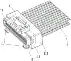
图1为实施例一中线缆连接器的立体结构示意图。FIG. 1 is a schematic three-dimensional structural diagram of the cable connector in the first embodiment.
图2为图1的零件分解图。FIG. 2 is an exploded view of the parts of FIG. 1 .
图3为线端绝缘主体的立体结构示意图。FIG. 3 is a schematic three-dimensional structure diagram of a wire end insulating body.
图4为实施例一中线端导电端子组的安装示意图。FIG. 4 is a schematic diagram of the installation of the conductive terminal group at the neutral line end according to the first embodiment.
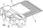
图5为实施例二中线缆连接器的立体结构示意图。FIG. 5 is a schematic three-dimensional structural diagram of the cable connector in the second embodiment.
图6为实施例三中线缆连接器的立体结构示意图。FIG. 6 is a schematic three-dimensional structural diagram of the cable connector in the third embodiment.
图7为实施例三中线端导电端子组的安装示意图。FIG. 7 is a schematic diagram of the installation of the conductive terminal group at the line end in the third embodiment.
图8为实施例四中线缆连接器的立体结构示意图。FIG. 8 is a schematic three-dimensional structure diagram of the cable connector in the fourth embodiment.
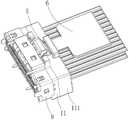
图9为实施例五中连接器组件的立体结构示意图。FIG. 9 is a schematic three-dimensional structural diagram of the connector assembly in the fifth embodiment.
图10为实施例五中板端连接器的立体结构示意图。FIG. 10 is a schematic three-dimensional structure diagram of the board end connector in the fifth embodiment.
图11为图9的零件分解图。FIG. 11 is an exploded view of the parts of FIG. 9 .
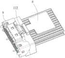
图12为实施例五中金属外壳的立体结构示意图。FIG. 12 is a schematic three-dimensional structural diagram of the metal casing in the fifth embodiment.
图13为线端导电端子组或板端导电端子组的导电端子排布示意图。FIG. 13 is a schematic diagram of the arrangement of the conductive terminals of the wire-end conductive terminal group or the board-end conductive terminal group.
图14为实施例六中连接器组件的立体结构示意图。FIG. 14 is a schematic three-dimensional structure diagram of the connector assembly in the sixth embodiment.
图15为实施例七中连接器组件的立体结构示意图。FIG. 15 is a schematic three-dimensional structural diagram of the connector assembly in the seventh embodiment.
图16为实施例八中连接器组件的立体结构示意图。16 is a schematic three-dimensional structural diagram of the connector assembly in the eighth embodiment.
图17为实施例九中连接器组件的立体结构示意图。17 is a schematic three-dimensional structural diagram of the connector assembly in the ninth embodiment.
图18为实施例九中金属外壳的立体结构示意图。FIG. 18 is a schematic three-dimensional structural diagram of the metal casing in the ninth embodiment.
图19为实施例十中连接器组件的立体结构示意图。FIG. 19 is a schematic three-dimensional structure diagram of the connector assembly in the tenth embodiment.
图20为实施例十一中连接器组件的立体结构示意图。FIG. 20 is a schematic three-dimensional structure diagram of the connector assembly in the eleventh embodiment.
图21为实施例十二中连接器组件的立体结构示意图。FIG. 21 is a schematic three-dimensional structure diagram of the connector assembly in the twelfth embodiment.
主要组件符号说明:1、线端绝缘主体;101、第一限位插槽;102、第二限位插槽;11、主体部;110、空腔;111、后盖;112、拉带孔;12、插入部;120、第一插接槽;13、卡扣部;130、卡扣槽;14、导向定位柱;201、地线端子;202、信号端子;21、第一导电端子组;211、第一连接部;22、第二导电端子组;221、第二连接部;23、塑胶固定件;3、线缆;31、第一线缆;32、第二线缆;4、内模;5、卡扣;51、固定部;52、弹性部;521、卡凸;53、按压部;6、拉带;7、板端绝缘主体;701、卡块;702、弹片槽;71、第二插接槽;72、绝缘插接板;8、板端导电端子组;801、地线端子;802、信号端子;81、导电塑胶条;82、第三导电端子组;83、第四导电端子组;9、金属外壳;90、第一U型槽;900、第二U型槽;901、锁孔;902、弹片;91、卡槽;92、导向孔;93、卡孔;94、固定臂;95、L型限位板;H:第一连接部和第二连接部之间的间距;A:地线端子的宽度;B:信号端子的宽度;a:地线端子和信号端子之间的间隙;b:信号端子和信号端子之间的间隙。Description of main component symbols: 1. Insulation body of wire end; 101, First limit slot; 102, Second limit slot; 11, Main body; 110, Cavity; 111, Back cover; ; 12, insert part; 120, first insertion slot; 13, buckle part; 130, buckle slot; 14, guide positioning column; 201, ground wire terminal; 202, signal terminal; 21, first conductive terminal group ; 211, the first connection part; 22, the second conductive terminal group; 221, the second connection part; 23, the plastic fixing part; 3, the cable; 31, the first cable; 32, the second cable; 4, Inner mold; 5. Buckle; 51. Fixing part; 52. Elastic part; 521. Snap-on protrusion; 53. Pressing part; 6. Pulling tape; 7. Board end insulation body; 701. Block; 71, the second socket; 72, the insulating plug board; 8, the board end conductive terminal group; 801, the ground terminal; 802, the signal terminal; 81, the conductive plastic strip; 82, the third conductive terminal group; 83, Fourth conductive terminal group; 9. Metal shell; 90, First U-shaped slot; 900, Second U-shaped slot; 901, Lock hole; 902, Shrapnel; 91, Card slot; 92, Guide hole; 93, Card hole ;94, fixed arm; 95, L-shaped limit plate; H: the distance between the first connection part and the second connection part; A: the width of the ground terminal; B: the width of the signal terminal; a: the ground terminal and the gap between the signal terminal; b: the gap between the signal terminal and the signal terminal.
具体实施方式Detailed ways
下面结合附图和具体实施方式,对本发明做进一步说明。The present invention will be further described below with reference to the accompanying drawings and specific embodiments.
实施例一Example 1
如图1-4所示,一种线缆连接器,包括线端绝缘主体1、线端导电端子组、线缆3、内模4和卡扣5。线端绝缘主体1包括主体部11、自主体部11前端面向前延伸形成的插入部12以及自主体部11的上表面向上及向前延伸形成的卡扣部13。卡扣部13延伸出主体部11部分与插入部12之间具有第一限位插槽101,卡扣部13的顶部开设有用于安装卡扣5的卡扣槽130。插入部12的前端开设有第一插接槽120,线端导电端子组设于第一插接槽120内。As shown in FIGS. 1-4 , a cable connector includes a wire
优选地,卡扣部13向前超出插入部12。Preferably, the
优选地,主体部11的前端面在插入部12的下方具有两个向前延伸的导向定位柱14,插入部12的底部与导向定位柱14的顶部之间具有第二限位插槽102,导向定位柱14向前超出插入部12。Preferably, the front end surface of the
卡扣5包括固定部51、自固定部51一端向上弯折形成的弹性部52以及自弹性部52末端向上倾斜延伸形成的按压部53,固定部51固定在卡扣槽130内。主体部11的内部开设有空腔110,主体部11在空腔110的后端设有一后盖111,后盖111通过卡扣固定在主体部11上。The
线端导电端子组包括第一导电端子组21、第二导电端子组22和塑胶固定件23,塑胶固定件23设在在空腔110内,塑胶固定件23可以分成上下两个固定件,也可以是是整体式固定件。第一导电端子组21和第二导电端子组22的同一端分别固定在塑胶固定件23上,另一端伸入第一插接槽120内并分别排布于第一插接槽120的上表面和下表面处。The wire-end conductive terminal group includes a first
第一导电端子组21在与塑胶固定件23连接的一端向下弯折形成第一连接部211,第二导电端子组22在与塑胶固定件23连接的一端向下弯折形成第二连接部221。第一连接部211和第二连接部221相互平行且前后错开设置,优选地,第一连接部211和第二连接部221之间的间距H为0.3~1.5mm。线缆3包括第一线缆31和第二线缆32,第一线缆31与第一连接部211焊接,第二线缆32与第二连接部221焊接。第一线缆31和第二线缆32均由主体部11的底部向下穿出。内模4设在空腔110内并将第一线缆31与第一连接部211焊点以及第二线缆32与第二连接部221焊点完全包覆。The first
如图13所示,第一导电端子组21和第二端子22排均由地线端子201和信号端子对依序交替排列而成,信号端子对由两个相互对称的信号端子202组成。As shown in FIG. 13 , the first
优选地,地线端子201的宽度A大于或等于信号端子202的宽度B,地线端子201和信号端子202之间的间隙a大于或等于两个信号端子202之间的间隙b。Preferably, the width A of the
实施例二Embodiment 2
如图5所示,本实施例与实施例一的区别仅在于:线缆连接器还包括拉带6,后盖111的上部开设有一拉带孔112,拉带6的一端穿过拉带孔112并与卡扣5的按压部53连接。本实施例的其余部分结构均与实施例一相同。As shown in FIG. 5 , the only difference between this embodiment and the first embodiment is that the cable connector further includes a
实施例三
如图6、图7所示,本实施例与实施例一的区别仅在于:第一导电端子组21和第二导电端子组22在与塑胶固定件23连接的一端没有弯折形成连接部。第一线缆31与第一导电端子组21靠近塑胶固定件23的一侧焊接在一起,第二线缆32与第二导电端子组22靠近塑胶固定件23的一侧焊接在一起,第一线缆31和第二线缆32均由后盖111向后穿出。本实施例的其余部分结构均与实施例一相同。As shown in FIG. 6 and FIG. 7 , the difference between this embodiment and the first embodiment is only that the first
实施例四
如图8所示,本实施例与实施例三的区别仅在于:线缆连接器还包括拉带6,后盖111的上部开设有一拉带孔112,拉带6的一端穿过拉带孔112并与卡扣5的按压部53连接。本实施例的其余部分结构均与实施例三相同。As shown in FIG. 8 , the only difference between this embodiment and the third embodiment is that the cable connector further includes a
实施例五
如图9-12所示,一种连接器组件,包括线缆连接器和板端连接器,线缆连接器为实施例一中的线缆连接器。As shown in FIGS. 9-12 , a connector assembly includes a cable connector and a board end connector, and the cable connector is the cable connector in the first embodiment.
板端连接器包括板端绝缘主体7、固设在板端绝缘主体7内部的板端导电端子组8以及套设在板端绝缘主体7外侧的金属外壳9,板端绝缘主体7的材质为塑胶。金属外壳9的侧边和底部分别设有锁孔901和弹片902,板端绝缘主体7的侧边和底部分别设有用于与锁孔901和弹片902卡接配合的卡块701和弹片槽702。The board-end connector includes a board-end insulating body 7, a board-end conductive terminal group 8 fixed inside the board-end insulating body 7, and a
板端绝缘主体7的内部开设有与插入部12形状相匹配的的第一插接槽71,插入部12插入第一插接槽71中,板端绝缘主体7的顶臂插入卡扣部13与插入部12之间的第一限位插槽101内。金属外壳9的顶部弯折形成有卡槽91,金属外壳9的底部弯折形成有两个供导向定位柱14插入的导向孔92。卡扣5在弹性部52的顶部设有两个卡凸521,金属外壳9在卡槽91的顶部开设有两个用于与两个卡凸521相卡接的卡孔93。金属外壳9的两侧以及卡槽91的两侧各设有两根朝着远离线缆连接器一侧延伸的固定臂94。The inside of the board end insulating body 7 is provided with a first insertion slot 71 that matches the shape of the
板端导电端子组8包括导电塑胶条81、第三导电端子组82和第四导电端子组83。板端绝缘主体7在第一插接槽71的内部设有绝缘插接板72,导电塑胶条81嵌入式地安装在绝缘插接板72的内部,第三导电端子组82和第四导电端子组83分别排布于绝缘插接板71的上表面和下表面处。绝缘插接板72的高度小于或等于第一插接槽120的高度,绝缘插接板72与板端绝缘主体7的侧壁之间具有供插入部12侧壁插入的间隙。板端导电端子组8插入第一插接槽120中并使得第一导电端子组21、第二导电端子组22分别与第三导电端子组82、第四导电端子组83接触连接。The board-end conductive terminal group 8 includes a conductive plastic strip 81 , a third conductive terminal group 82 and a fourth conductive terminal group 83 . The board-end insulating body 7 is provided with an insulating plug-in board 72 inside the first plug-in slot 71 , the conductive plastic strip 81 is embedded in the interior of the insulating plug-in board 72 , the third conductive terminal group 82 and the fourth conductive terminal The groups 83 are respectively arranged at the upper surface and the lower surface of the insulating plug board 71 . The height of the insulating plug-in board 72 is less than or equal to the height of the first plug-in
如图13所示,第三导电端子组82和第四导电端子组83均由地线端子801和信号端子对依序交替排列而成,信号端子对由两个相互对称的信号端子802组成,所有的地线端子801均与导电塑胶条81电连接。As shown in FIG. 13 , the third conductive terminal group 82 and the fourth conductive terminal group 83 are formed by the
优选地,地线端子801的宽度A大于或等于信号端子802的宽度B,地线端子801和信号端子802之间的间隙a大于或等于两个信号端子802之间的间隙b。Preferably, the width A of the
卡扣部13前端的底部与插入部12的顶部之间的间距大于或等于板端绝缘主体71顶板的厚度,使得插入部12插入第一插接槽71时,板端绝缘主体71的顶板能够插入到卡扣部13与插入部12之间形成的间隙内。插入部12的底部与导向定位柱14的顶部之间的第二限位插槽102的高度大于或等于板端绝缘主体71底板的厚度,使得插入部12插入第一插接槽71时,板端绝缘主体71的底板能够插入到插入部12与导向定位柱14之间形成的第二限位插槽102内。绝缘插接板72与板端绝缘主体7的侧壁之间的间距大于或等于插入部12侧壁的厚度,使得插入部12的两边侧壁能够插入到绝缘插接板72与板端绝缘主体7形成的两个侧边间隙内。The distance between the bottom of the front end of the
本发明的工作原理为:The working principle of the present invention is:
组装连接器组件:将线端连接器组装完成后,对好位置,将线端连接器的插入部12、卡扣部13和两个导向定位柱14分别插入板端连接器的第一插接槽71、卡槽91和两个导向孔92中,两个导向定位柱14能够对整个线端连接器的插接进行导向并防止产品受力扭转、歪斜。与此同时,板端连接器上的绝缘插接板72插入到线端连接器插入部12的第一插接槽120中,第三导电端子组与第一导电端子组接触导通,第四导电端子组和第二导电端子组接触导通。线端连接器顶部的两个卡凸521卡入板端连接器的两个卡孔93中实现固定。Assembling the connector assembly: After assembling the wire end connector, align the position, and insert the
解锁连接器组件:按压卡扣5的按压部53使得其向下运动,弹性部52跟随按压部53向下运动,弹性部52顶部的两个卡凸521从金属外壳9的两个卡孔93中脱离,拉动线缆连接器使线缆连接器从板端连接器中脱离,解锁完成。Unlock the connector assembly: press the
实施例六
如图14所示,一种连接器组件,包括线缆连接器和板端连接器,线缆连接器为实施例二中的线缆连接器。本实施例板端连接器的结构与实施例五相同。As shown in FIG. 14 , a connector assembly includes a cable connector and a board end connector, and the cable connector is the cable connector in the second embodiment. The structure of the board end connector of this embodiment is the same as that of the fifth embodiment.
本实施例的连接器组件在解锁时,拉动拉带6,拉带6拉动卡扣5的按压部53向下运动,弹性部52跟随按压部53向下运动,弹性部52顶部的两个卡凸521从金属外壳9的两个卡孔93中脱离,继续拉动拉带6,将线端连接器从板端连接器中脱离,解锁完成。When the connector assembly of this embodiment is unlocked, the
实施例七Embodiment 7
如图15所示,一种连接器组件,包括线缆连接器和板端连接器,线缆连接器为实施例三中的线缆连接器。本实施例板端连接器的结构与实施例五相同。As shown in FIG. 15 , a connector assembly includes a cable connector and a board end connector, and the cable connector is the cable connector in the third embodiment. The structure of the board end connector of this embodiment is the same as that of the fifth embodiment.
本实施例的连接器组件在解锁时,按压卡扣5的按压部53使得其向下运动,弹性部52跟随按压部53向下运动,弹性部52顶部的两个卡凸521从金属外壳9的两个卡孔93中脱离,拉动线缆连接器使线缆连接器从板端连接器中脱离,解锁完成。When the connector assembly of this embodiment is unlocked, the
实施例八Embodiment 8
如图16所示,一种连接器组件,包括线缆连接器和板端连接器,线缆连接器为实施例四中的线缆连接器。本实施例板端连接器的结构与实施例五相同。As shown in FIG. 16 , a connector assembly includes a cable connector and a board end connector, and the cable connector is the cable connector in the fourth embodiment. The structure of the board end connector of this embodiment is the same as that of the fifth embodiment.
本实施例的连接器组件在解锁时,拉动拉带6,拉带6拉动卡扣5的按压部53向下运动,弹性部52跟随按压部53向下运动,弹性部52顶部的两个卡凸521从金属外壳9的两个卡孔93中脱离,继续拉动拉带6,将线端连接器从板端连接器中脱离,解锁完成。When the connector assembly of this embodiment is unlocked, the
实施例九
如图17、18所示,一种连接器组件,包括线缆连接器和板端连接器,线缆连接器为实施例一中的线缆连接器。本实施例与实施例五的区别仅在于:金属外壳9的两侧分别朝着线缆连接器的一侧延伸并形成两个用于对线缆连接器进行左右限位的L型限位板95。金属外壳9顶部在卡槽91的前端形成有第一U型槽90,线缆连接器的卡扣部13后端容置于第一U型槽90中,金属外壳9底部的前端形成有第二U型槽900,线缆连接器的主体部11容置于第二U型槽900中。本实施例其余部分结构均与实施例五相同。As shown in FIGS. 17 and 18 , a connector assembly includes a cable connector and a board end connector, and the cable connector is the cable connector in the first embodiment. The only difference between this embodiment and the fifth embodiment is that the two sides of the
本实施例中,金属外壳9前面和后面的高度低于金属外壳9的侧面,这种结构可以有效降低产品匹配后的总高度而且又可以提高产品的接触可靠性,防止线缆连接器左右摇晃。In this embodiment, the heights of the front and rear of the
实施例十Embodiment ten
如图19所示,一种连接器组件,包括线缆连接器和板端连接器,线缆连接器为实施例二中的线缆连接器。本实施例的板端连接器结构与实施例九相同。As shown in FIG. 19 , a connector assembly includes a cable connector and a board end connector, and the cable connector is the cable connector in the second embodiment. The structure of the board end connector of this embodiment is the same as that of the ninth embodiment.
实施例十一
如图20所示,一种连接器组件,包括线缆连接器和板端连接器,线缆连接器为实施例三中的线缆连接器。本实施例的板端连接器结构与实施例九相同。As shown in FIG. 20 , a connector assembly includes a cable connector and a board end connector, and the cable connector is the cable connector in the third embodiment. The structure of the board end connector of this embodiment is the same as that of the ninth embodiment.
实施例十二
如图21所示,一种连接器组件,包括线缆连接器和板端连接器,线缆连接器为实施例四中的线缆连接器。本实施例的板端连接器结构与实施例九相同。As shown in FIG. 21 , a connector assembly includes a cable connector and a board end connector, and the cable connector is the cable connector in the fourth embodiment. The structure of the board end connector of this embodiment is the same as that of the ninth embodiment.
尽管结合优选实施方案具体展示和介绍了本发明,但所属领域的技术人员应该明白,在不脱离所附权利要求书所限定的本发明的精神和范围内,在形式上和细节上对本发明做出各种变化,均为本发明的保护范围。Although the present invention has been particularly shown and described in connection with preferred embodiments, it will be understood by those skilled in the art that changes in form and detail can be made in the present invention without departing from the spirit and scope of the invention as defined by the appended claims. Various changes are within the protection scope of the present invention.
Claims (20)
Translated fromChinesePriority Applications (4)
| Application Number | Priority Date | Filing Date | Title |
|---|---|---|---|
| CN201911083793.7ACN110729594B (en) | 2019-11-07 | 2019-11-07 | Cable connector and connector assembly |
| US16/746,987US10886649B1 (en) | 2019-11-07 | 2020-01-20 | Cable connector and connector assembly |
| TW109214650UTWM612510U (en) | 2019-11-07 | 2020-11-05 | Cable connector and connector assembly |
| TW109138716ATWI751774B (en) | 2019-11-07 | 2020-11-05 | Cable connector and connector assembly |
Applications Claiming Priority (1)
| Application Number | Priority Date | Filing Date | Title |
|---|---|---|---|
| CN201911083793.7ACN110729594B (en) | 2019-11-07 | 2019-11-07 | Cable connector and connector assembly |
Publications (2)
| Publication Number | Publication Date |
|---|---|
| CN110729594Atrue CN110729594A (en) | 2020-01-24 |
| CN110729594B CN110729594B (en) | 2024-12-31 |
Family
ID=69225118
Family Applications (1)
| Application Number | Title | Priority Date | Filing Date |
|---|---|---|---|
| CN201911083793.7AActiveCN110729594B (en) | 2019-11-07 | 2019-11-07 | Cable connector and connector assembly |
Country Status (2)
| Country | Link |
|---|---|
| US (1) | US10886649B1 (en) |
| CN (1) | CN110729594B (en) |
Cited By (14)
| Publication number | Priority date | Publication date | Assignee | Title |
|---|---|---|---|---|
| CN111463615A (en)* | 2020-04-08 | 2020-07-28 | 东莞立讯技术有限公司 | Wire end connector, plate end connector and connector |
| CN112054323A (en)* | 2020-09-15 | 2020-12-08 | 安费诺电子装配(厦门)有限公司 | Cable connector |
| CN112952423A (en)* | 2021-02-08 | 2021-06-11 | 安费诺电子装配(厦门)有限公司 | Board end connector and connector assembly |
| CN113285299A (en)* | 2021-05-08 | 2021-08-20 | 富加宜连接器(东莞)有限公司 | High-speed backplane connector with locking function |
| TWI752615B (en)* | 2020-09-04 | 2022-01-11 | 英業達股份有限公司 | Connector assembly and locking elastic piece |
| CN113964577A (en)* | 2021-09-17 | 2022-01-21 | 深圳金信诺高新技术股份有限公司 | Connection structure, wire end connector and electrical connector |
| CN114024172A (en)* | 2021-11-02 | 2022-02-08 | 安费诺电子装配(厦门)有限公司 | Cable connector and connector assembly |
| CN114142286A (en)* | 2020-09-04 | 2022-03-04 | 安费诺电子装配(厦门)有限公司 | Cable connector and connector assembly |
| JP2022063421A (en)* | 2020-10-12 | 2022-04-22 | 日本航空電子工業株式会社 | connector |
| JP2022063418A (en)* | 2020-10-12 | 2022-04-22 | 日本航空電子工業株式会社 | connector |
| CN114696158A (en)* | 2020-12-28 | 2022-07-01 | 唐虞企业股份有限公司 | Connector assembly and connector thereof |
| US11569613B2 (en) | 2021-04-19 | 2023-01-31 | Amphenol East Asia Ltd. | Electrical connector having symmetrical docking holes |
| US11728585B2 (en) | 2020-06-17 | 2023-08-15 | Amphenol East Asia Ltd. | Compact electrical connector with shell bounding spaces for receiving mating protrusions |
| US11831092B2 (en) | 2020-07-28 | 2023-11-28 | Amphenol East Asia Ltd. | Compact electrical connector |
Families Citing this family (7)
| Publication number | Priority date | Publication date | Assignee | Title |
|---|---|---|---|---|
| CN111355100B (en)* | 2018-12-21 | 2023-12-19 | 富士康(昆山)电脑接插件有限公司 | plug connector |
| TWI782354B (en)* | 2020-04-24 | 2022-11-01 | 大陸商東莞立訊技術有限公司 | Board end connector and connector assembly |
| CN114142293B (en)* | 2020-09-02 | 2023-10-03 | 英业达科技有限公司 | Connector assembly and buckle shrapnel |
| CN114336173B (en)* | 2022-01-25 | 2024-12-06 | 贸联电子(昆山)有限公司 | Connectors |
| CN114883858A (en)* | 2022-05-06 | 2022-08-09 | 东莞立讯技术有限公司 | Pull-strap connector and method of manufacturing the same |
| CN115360542A (en)* | 2022-08-04 | 2022-11-18 | 安费诺东亚电子科技(深圳)有限公司 | Connector |
| TWI845358B (en)* | 2023-06-26 | 2024-06-11 | 宏致電子股份有限公司 | Plug connector and its matching socket connector |
Citations (5)
| Publication number | Priority date | Publication date | Assignee | Title |
|---|---|---|---|---|
| JP2010129404A (en)* | 2008-11-28 | 2010-06-10 | Molex Inc | Wire-to-board connector |
| US20130052851A1 (en)* | 2011-08-31 | 2013-02-28 | Lanto Electronic Limited | Receptacle connector, plug connector and connector assembly thereof with improved locking structure |
| CN208209042U (en)* | 2018-03-30 | 2018-12-07 | 安费诺电子装配(厦门)有限公司 | A kind of small-sized ultrahigh speed wire and cable connector and connector assembly |
| CN208738551U (en)* | 2018-05-30 | 2019-04-12 | 立讯精密工业股份有限公司 | High-density MINI chip side high-speed connector and printed circuit board layout structure |
| CN208797272U (en)* | 2018-08-29 | 2019-04-26 | 安费诺电子装配(厦门)有限公司 | A kind of high-speed cable connector |
Family Cites Families (8)
| Publication number | Priority date | Publication date | Assignee | Title |
|---|---|---|---|---|
| US6655979B1 (en)* | 2002-10-15 | 2003-12-02 | Hon Hai Precision Ind. Co., Ltd. | Cable end connector with locking member |
| US20050101176A1 (en)* | 2003-11-10 | 2005-05-12 | Kachlic Jerry D. | Latch for electrical connector |
| US6860750B1 (en)* | 2003-12-05 | 2005-03-01 | Hon Hai Precision Ind. Co., Ltd. | Cable end connector assembly having locking member |
| US7083459B1 (en)* | 2005-04-20 | 2006-08-01 | Bizlink Technology, Inc. | Latching connector assembly |
| US7581978B1 (en)* | 2008-08-06 | 2009-09-01 | Tyco Electronics Corporation | Connector assembly with a latch |
| TWM482180U (en)* | 2014-02-07 | 2014-07-11 | Wieson Technologies Co Ltd | Plug connector structure |
| CN209016312U (en)* | 2018-07-31 | 2019-06-21 | 安费诺电子装配(厦门)有限公司 | A kind of line-end connector and connector assembly |
| US10630022B2 (en)* | 2018-08-29 | 2020-04-21 | Amphenol Assembletech (Xiamen) Co., Ltd | High-speed cable connector |
- 2019
- 2019-11-07CNCN201911083793.7Apatent/CN110729594B/enactiveActive
- 2020
- 2020-01-20USUS16/746,987patent/US10886649B1/enactiveActive
Patent Citations (5)
| Publication number | Priority date | Publication date | Assignee | Title |
|---|---|---|---|---|
| JP2010129404A (en)* | 2008-11-28 | 2010-06-10 | Molex Inc | Wire-to-board connector |
| US20130052851A1 (en)* | 2011-08-31 | 2013-02-28 | Lanto Electronic Limited | Receptacle connector, plug connector and connector assembly thereof with improved locking structure |
| CN208209042U (en)* | 2018-03-30 | 2018-12-07 | 安费诺电子装配(厦门)有限公司 | A kind of small-sized ultrahigh speed wire and cable connector and connector assembly |
| CN208738551U (en)* | 2018-05-30 | 2019-04-12 | 立讯精密工业股份有限公司 | High-density MINI chip side high-speed connector and printed circuit board layout structure |
| CN208797272U (en)* | 2018-08-29 | 2019-04-26 | 安费诺电子装配(厦门)有限公司 | A kind of high-speed cable connector |
Cited By (22)
| Publication number | Priority date | Publication date | Assignee | Title |
|---|---|---|---|---|
| CN111463615A (en)* | 2020-04-08 | 2020-07-28 | 东莞立讯技术有限公司 | Wire end connector, plate end connector and connector |
| US11728585B2 (en) | 2020-06-17 | 2023-08-15 | Amphenol East Asia Ltd. | Compact electrical connector with shell bounding spaces for receiving mating protrusions |
| US11831092B2 (en) | 2020-07-28 | 2023-11-28 | Amphenol East Asia Ltd. | Compact electrical connector |
| CN114142286A (en)* | 2020-09-04 | 2022-03-04 | 安费诺电子装配(厦门)有限公司 | Cable connector and connector assembly |
| CN114142286B (en)* | 2020-09-04 | 2025-06-10 | 安费诺电子装配(厦门)有限公司 | Cable connector and connector assembly |
| TWI752615B (en)* | 2020-09-04 | 2022-01-11 | 英業達股份有限公司 | Connector assembly and locking elastic piece |
| CN112054323A (en)* | 2020-09-15 | 2020-12-08 | 安费诺电子装配(厦门)有限公司 | Cable connector |
| JP7591900B2 (en) | 2020-10-12 | 2024-11-29 | 日本航空電子工業株式会社 | connector |
| JP2022063421A (en)* | 2020-10-12 | 2022-04-22 | 日本航空電子工業株式会社 | connector |
| JP2022063418A (en)* | 2020-10-12 | 2022-04-22 | 日本航空電子工業株式会社 | connector |
| JP7467310B2 (en) | 2020-10-12 | 2024-04-15 | 日本航空電子工業株式会社 | connector |
| CN114696158A (en)* | 2020-12-28 | 2022-07-01 | 唐虞企业股份有限公司 | Connector assembly and connector thereof |
| CN114696158B (en)* | 2020-12-28 | 2025-04-25 | 唐虞企业股份有限公司 | Connector assembly and connector thereof |
| CN112952423A (en)* | 2021-02-08 | 2021-06-11 | 安费诺电子装配(厦门)有限公司 | Board end connector and connector assembly |
| US11942724B2 (en) | 2021-04-19 | 2024-03-26 | Amphenol East Asia Ltd. | Electrical connector having symmetrical docking holes |
| US11569613B2 (en) | 2021-04-19 | 2023-01-31 | Amphenol East Asia Ltd. | Electrical connector having symmetrical docking holes |
| CN113285299A (en)* | 2021-05-08 | 2021-08-20 | 富加宜连接器(东莞)有限公司 | High-speed backplane connector with locking function |
| CN113285299B (en)* | 2021-05-08 | 2025-06-27 | 富加宜连接器(东莞)有限公司 | A high-speed backplane connector with locking function |
| CN113964577B (en)* | 2021-09-17 | 2024-08-16 | 深圳金信诺高新技术股份有限公司 | Connection structure, wire end connector and electrical connector |
| CN113964577A (en)* | 2021-09-17 | 2022-01-21 | 深圳金信诺高新技术股份有限公司 | Connection structure, wire end connector and electrical connector |
| CN114024172B (en)* | 2021-11-02 | 2023-11-21 | 安费诺电子装配(厦门)有限公司 | Cable connector and connector assembly |
| CN114024172A (en)* | 2021-11-02 | 2022-02-08 | 安费诺电子装配(厦门)有限公司 | Cable connector and connector assembly |
Also Published As
| Publication number | Publication date |
|---|---|
| CN110729594B (en) | 2024-12-31 |
| US10886649B1 (en) | 2021-01-05 |
Similar Documents
| Publication | Publication Date | Title |
|---|---|---|
| CN110729594A (en) | A cable connector and connector assembly | |
| CN210723480U (en) | Cable connector and connector assembly | |
| TWI840661B (en) | Electrical connector assembly | |
| US9653849B2 (en) | Electrical connector having good anti-EMI perfprmance | |
| US6830478B1 (en) | Micro coaxial connector assembly with latching means | |
| TWI751774B (en) | Cable connector and connector assembly | |
| US9437981B2 (en) | Cable connector assembly with improved grounding structure | |
| CN201868594U (en) | Electric connector | |
| US6913485B2 (en) | Micro coaxial cable assembly having improved contacts | |
| CN205429247U (en) | electrical connector | |
| CN210156669U (en) | Two-side unlocking connector assembly | |
| US6808410B1 (en) | Cable connector assembly having pulling mechanism | |
| TWI801957B (en) | Electrical connector | |
| CN210350162U (en) | Electrical connector | |
| CN110783774A (en) | High-speed electrical connectors and contact modules | |
| CN212968224U (en) | Cable connector and connector assembly | |
| CN204947182U (en) | Electric connector | |
| US6210237B1 (en) | Multi-port modular jack assembly and method for making the same | |
| CN212412347U (en) | Electrical connector | |
| US8162679B2 (en) | Insulation displacement contact and electric connector using the same | |
| CN113422254B (en) | Receptacle Connector and High Speed Micro Coaxial Connector Assemblies | |
| CN114142286B (en) | Cable connector and connector assembly | |
| US7445470B2 (en) | Electrical connector with improved housing | |
| CN101931150A (en) | cable connector | |
| CN210182689U (en) | Front unlocking connector assembly |
Legal Events
| Date | Code | Title | Description |
|---|---|---|---|
| PB01 | Publication | ||
| PB01 | Publication | ||
| SE01 | Entry into force of request for substantive examination | ||
| SE01 | Entry into force of request for substantive examination | ||
| GR01 | Patent grant | ||
| GR01 | Patent grant |